EP4105634A1 - Battery bending test system and battery bending test method - Google Patents
Battery bending test system and battery bending test method Download PDFInfo
- Publication number
- EP4105634A1 EP4105634A1 EP20924610.7A EP20924610A EP4105634A1 EP 4105634 A1 EP4105634 A1 EP 4105634A1 EP 20924610 A EP20924610 A EP 20924610A EP 4105634 A1 EP4105634 A1 EP 4105634A1
- Authority
- EP
- European Patent Office
- Prior art keywords
- battery
- plate element
- bending test
- pressing
- fastening device
- Prior art date
- Legal status (The legal status is an assumption and is not a legal conclusion. Google has not performed a legal analysis and makes no representation as to the accuracy of the status listed.)
- Granted
Links
Images



Classifications
-
- G—PHYSICS
- G01—MEASURING; TESTING
- G01N—INVESTIGATING OR ANALYSING MATERIALS BY DETERMINING THEIR CHEMICAL OR PHYSICAL PROPERTIES
- G01N3/00—Investigating strength properties of solid materials by application of mechanical stress
- G01N3/02—Details
- G01N3/04—Chucks
-
- G—PHYSICS
- G01—MEASURING; TESTING
- G01N—INVESTIGATING OR ANALYSING MATERIALS BY DETERMINING THEIR CHEMICAL OR PHYSICAL PROPERTIES
- G01N3/00—Investigating strength properties of solid materials by application of mechanical stress
- G01N3/02—Details
-
- G—PHYSICS
- G01—MEASURING; TESTING
- G01N—INVESTIGATING OR ANALYSING MATERIALS BY DETERMINING THEIR CHEMICAL OR PHYSICAL PROPERTIES
- G01N3/00—Investigating strength properties of solid materials by application of mechanical stress
- G01N3/20—Investigating strength properties of solid materials by application of mechanical stress by applying steady bending forces
-
- G—PHYSICS
- G01—MEASURING; TESTING
- G01R—MEASURING ELECTRIC VARIABLES; MEASURING MAGNETIC VARIABLES
- G01R31/00—Arrangements for testing electric properties; Arrangements for locating electric faults; Arrangements for electrical testing characterised by what is being tested not provided for elsewhere
- G01R31/36—Arrangements for testing, measuring or monitoring the electrical condition of accumulators or electric batteries, e.g. capacity or state of charge [SoC]
-
- H—ELECTRICITY
- H01—ELECTRIC ELEMENTS
- H01M—PROCESSES OR MEANS, e.g. BATTERIES, FOR THE DIRECT CONVERSION OF CHEMICAL ENERGY INTO ELECTRICAL ENERGY
- H01M10/00—Secondary cells; Manufacture thereof
- H01M10/42—Methods or arrangements for servicing or maintenance of secondary cells or secondary half-cells
- H01M10/4285—Testing apparatus
-
- G—PHYSICS
- G01—MEASURING; TESTING
- G01N—INVESTIGATING OR ANALYSING MATERIALS BY DETERMINING THEIR CHEMICAL OR PHYSICAL PROPERTIES
- G01N2203/00—Investigating strength properties of solid materials by application of mechanical stress
- G01N2203/0014—Type of force applied
- G01N2203/0023—Bending
-
- G—PHYSICS
- G01—MEASURING; TESTING
- G01N—INVESTIGATING OR ANALYSING MATERIALS BY DETERMINING THEIR CHEMICAL OR PHYSICAL PROPERTIES
- G01N2203/00—Investigating strength properties of solid materials by application of mechanical stress
- G01N2203/02—Details not specific for a particular testing method
- G01N2203/026—Specifications of the specimen
- G01N2203/0262—Shape of the specimen
- G01N2203/0278—Thin specimens
- G01N2203/0282—Two dimensional, e.g. tapes, webs, sheets, strips, disks or membranes
-
- G—PHYSICS
- G01—MEASURING; TESTING
- G01N—INVESTIGATING OR ANALYSING MATERIALS BY DETERMINING THEIR CHEMICAL OR PHYSICAL PROPERTIES
- G01N2203/00—Investigating strength properties of solid materials by application of mechanical stress
- G01N2203/02—Details not specific for a particular testing method
- G01N2203/04—Chucks, fixtures, jaws, holders or anvils
- G01N2203/0423—Chucks, fixtures, jaws, holders or anvils using screws
-
- G—PHYSICS
- G01—MEASURING; TESTING
- G01N—INVESTIGATING OR ANALYSING MATERIALS BY DETERMINING THEIR CHEMICAL OR PHYSICAL PROPERTIES
- G01N2203/00—Investigating strength properties of solid materials by application of mechanical stress
- G01N2203/02—Details not specific for a particular testing method
- G01N2203/04—Chucks, fixtures, jaws, holders or anvils
- G01N2203/0435—Chucks, fixtures, jaws, holders or anvils modifying the type of the force applied, e.g. the chuck transforms a compressive machine for applying a bending test
-
- Y—GENERAL TAGGING OF NEW TECHNOLOGICAL DEVELOPMENTS; GENERAL TAGGING OF CROSS-SECTIONAL TECHNOLOGIES SPANNING OVER SEVERAL SECTIONS OF THE IPC; TECHNICAL SUBJECTS COVERED BY FORMER USPC CROSS-REFERENCE ART COLLECTIONS [XRACs] AND DIGESTS
- Y02—TECHNOLOGIES OR APPLICATIONS FOR MITIGATION OR ADAPTATION AGAINST CLIMATE CHANGE
- Y02E—REDUCTION OF GREENHOUSE GAS [GHG] EMISSIONS, RELATED TO ENERGY GENERATION, TRANSMISSION OR DISTRIBUTION
- Y02E60/00—Enabling technologies; Technologies with a potential or indirect contribution to GHG emissions mitigation
- Y02E60/10—Energy storage using batteries
Definitions
- the embodiments of the present application relate to the field of batteries, and in particular, to a battery bending test system and method.
- Batteries are extensively used in various electronic products and electric vehicles. However, bending or folding may occur to batteries in practical applications. For example, upon dismantlement and replacement, a battery can only be disconnected with a hard pull as it is firmly attached to the battery compartment. At this time, the battery is subjected to the bending force. In another example, when the device that holds the battery is subjected to the bending force, the battery inside the device is not immune to the bending force. Such bending conditions as described may lead to safety hazards with batteries.
- One of the objects of the embodiments of the present application is to provide a battery bending test system and method, which can simulate a reasonable battery bending condition, thereby realizing a reasonable evaluation of the safety performance of the battery when the battery is subjected to a bending force.
- a battery bending test system includes: a fastening device having an arrangement surface configured to hold the battery; a pressing device configured to press the battery to bend; and a load-bearing device configured to bear the fastening device, the load-bearing device having a reference surface for bearing the fastening device, wherein a first angle ⁇ is formed between the arrangement surface and the reference surface, and the range of first angle ⁇ is 0° ⁇ ⁇ ⁇ 90°.
- the first angle ⁇ is about 30°, about 45°, or about 60°.
- the pressing device includes a pressing head, which is configured to press the battery along the direction perpendicular to the reference surface.
- the fastening device includes a first plate element, and a second plate element parallel to the first plate element for holding part of the battery.
- the first plate element has the arrangement surface and a first lateral surface perpendicular to the arrangement surface, and the pressing head has a distance D from the first lateral surface along a direction of the arrangement surface extending, when the pressing head is configured to begin to press the battery.
- the distance D is about 20 mm.
- the fastening device further includes: a third plate element parallel to the first plate element and a first rod-shaped element penetrating the second plate element and connected to the first plate element and the third plate element, wherein the second plate element is located between the first plate element and the third plate element, and is movable between the first plate element and the third plate element along the first rod-shaped element.
- the fastening device further includes: a second rod-shaped element penetrating the third plate element having a first end and a second end opposite to the first end; a fourth plate element connected to the first end and to the second plate element; and a third rod-shaped element connected to the second end, the third rod-shaped element being configured to rotate so that the second plate element is driven by the second rod-shaped element to move along the first rod-shaped element.
- the pressing device is configured to descend at a predetermined speed to contact the battery.
- the pressing device further includes a connecting element configured to be connected to the pressing head and an actuating element configured to be connected to the connecting element and to control displacement and pressing force of the pressing head.
- the load-bearing device includes an angular adjustment element configured to be connected to the fastening device and including a bearing surface bearing the fastening device, the bearing surface being parallel to the arrangement surface of the fastening device.
- the angular adjustment element is configured to connect to the reference surface.
- the load-bearing device includes a base connected to the angular adjustment element.
- a data acquisition device is further included for collecting battery parameters of the battery to judge the safety performance of the battery.
- a battery bending test method includes bearing the fastening device by means of a load-bearing device, the load-bearing device having a reference surface bearing the fastening device; holding the battery by means of the fastening device, the fastening device having an arrangement surface configured to hold the battery, wherein a first angle ⁇ is formed between the arrangement surface and the reference surface, the range of the first angle ⁇ being 0° ⁇ ⁇ ⁇ 90°; pressing the battery to bend by means of a pressing device; and squeezing the battery to a set condition.
- the battery bending test system and method provided by the embodiments of the application can precisely control the bending angle and bending morphology of the battery, reasonably evaluate the safety performance of the battery when the battery is subjected to the bending force, thus meeting expectations of the safety test.
- a term may refer to a range of variation less than or equal to ⁇ 10% of the value, such as less than or equal to ⁇ 5%, less than or equal to ⁇ 4%, less than or equal to ⁇ 3%, less than or equal to ⁇ 2%, less than or equal to ⁇ 1%, less than or equal to ⁇ 0.5%, less than or equal to ⁇ 0.1%, or less than or equal to ⁇ 0.05%.
- the difference between two values is less than or equal to ⁇ 10% of the average of the values (e.g., less than or equal to ⁇ 5%, less than or equal to ⁇ 4%, less than or equal to ⁇ 3%, less than or equal to ⁇ 2%, less than or equal to ⁇ 1%, less than or equal to ⁇ 0.5%, less than or equal to ⁇ 0.1%, or less than or equal to ⁇ 0.05%), the two values are considered to be "substantially" the same.
- first,” “second,” “third,” and the like may be used herein to distinguish different components of one figure or a series of figures.
- the terms “first,” “second,” “third,” and the like are not intended to describe corresponding components.
- the wordings "provide,” “connect,” “couple,” “fix,” and similar thereto are used extensively in the present application, and a person skilled in the art may, depending on the specific circumstances, understand the described wordings as, for example, fixed connection, detachable connection, or integrated connection; it can also be understood as mechanical connection or electrical connection; or as direct connection or indirect connection through an intermediary structure; or as internal communication between two components.
- a list of items following the terms "a single one of,” “one of,” “one kind of,” or other similar terms may mean any one of the listed items.
- the phrase “a single one of A and B” means only A or only B.
- the phrase “a single one of A, B, and C” means only A; only B; or only C.
- Item A may include a single element or multiple elements.
- Item B may include a single element or multiple elements.
- Item C may include a single element or multiple elements.
- a list of items following the terms "at least a single one of,” “at least one of,” “at least one kind of,” or other similar terms may mean any combination of the listed items.
- the phrase “at least a single one of A and B” means only A; only B; or A and B.
- the phrase "at least a single one of A, B, and C” means only A; or only B; only C; A and B (excluding C); A and C (excluding B); B and C (excluding A); or all of A, B and C.
- Item A may include a single element or multiple elements.
- Item B may include a single element or multiple elements.
- Item C may include a single element or multiple elements.
- the General Technical Requirement of Lithium-ion Cells for Wireless Headset proposes a method of bending batteries, which requires an operating temperature of 20 ⁇ 5 degrees Celsius.
- the battery may be a cuboid having four edges extending in a length direction and four edges extending in a width direction, wherein a first edge and a second edge extend in the length direction, a third edge and a fourth edge extend in the width direction, and the third edge and the fourth edge are both located between the first edge and the second edge.
- the battery to be tested is fully charged according to manufacturer instructions for battery.
- the battery is held loosely between two clamps of a testing machine, one of the clamp being movable to bend the battery.
- the first edge, the second edge, the third edge and the fourth edge of the battery are bent to and fro up to 250 times at a frequency of 0.5 Hz.
- the battery can be bent using the device at an angle ranging from 45 degrees to 60 degrees.
- the described test method does not accurately and properly simulate a common condition when the battery is subjected to bending force, and cannot reasonably evaluate the safety performance in practical applications, thus failing to meet expectations of the safety test.
- Another method is further provided by the existing art. Two metal blocks are placed horizontally, on which Teflon tapes are applied; the battery is tightly wrapped with Teflon bands followed by being placed between the two metal blocks to ensure that the battery does not slide between the blocks. Then, the battery is pressed vertically downward by using a pressing head.
- the battery and the metal blocks slide over each other easily, and thus the test cannot run smoothly.
- the contact edges between the metal blocks and the battery are seamed edges that are likely to render the battery bearing a shear force, which does not conform to the practical condition of the battery.
- the control over the battery only provides a bending angle of a small range from about 45 degrees to 60 degrees.
- a greater range of the bending angle is desired to achieve, such as about 0 degree to 90 degrees, or about 0 degree to 120 degrees, or about 0 degree to 180 degrees, it is difficult to attain with existing test methods or systems. Furthermore, the accurate control over the bending angle and bending morphology of the battery is not achievable with two described methods.
- the embodiments of the present application provide a novel battery bending test system and method by which the battery is bendable to a predetermined angle, or subjected to a predetermined pressure, or can achieve a predetermined displacement, so that precise control over the bending angle, displacement of the battery, and pressure exerted thereon are achieved to effectively and reasonably evaluate the safety performance of the battery based on a feasible battery bending test.
- the battery can be firmly held to prevent the battery and the fastening device from sliding over each other during the testing process, and thus the test can be conducted more conveniently and efficiently.
- the battery can bend at an angle ranging from about 0 degree to 180 degrees instead of being limited to about 45 degrees to 60 degrees.
- FIG. 1 is a schematic perspective view showing a battery bending test system 10 according to one embodiment of the present application.
- FIG. 1b is a top view showing the battery along a Z direction of the battery bending test system 10 of the embodiment shown in FIG. 1a .
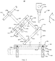
- FIG. 2 is a schematic lateral view showing the battery bending test system 10 of the embodiment shown in FIG. 1a , which illustrates a state of the battery bending test system 10 without holding the battery.
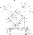
- FIG. 3 is a schematic lateral view showing the battery bending test system 10 of the embodiment shown in FIG. 1a , which illustrates a state of the battery bending test system 10 when holding the battery.
- FIG. 4 is a schematic enlargement view of portion A-A of the battery bending test system 10 of the embodiment shown in FIG.
- FIG. 5 is a schematic perspective view showing the fastening device of the battery bending test system 10 of the embodiment shown in FIG. 1a .
- the battery bending test system 10 according to one embodiment of the present application includes a fastening device 100, a pressing device 200, a load-bearing device 300, an angular adjustment element 400 and a battery 500.
- the fastening device 100 may be configured to hold the battery 500.
- the fastening device 100 may include a first plate element 101, a second plate element 103, a third plate element 105, a first rod-shaped element 107, a second rod-shaped element 109, a fourth plate element 111, and a third rod-shaped element 113.
- the material of the first plate element 101, the second plate element 103, the third plate element 105, the first rod-shaped member 107, the second rod-shaped element 109, the fourth plate element 111, and the third rod-shaped element 113 may be metallic or nonmetallic material having proper hardness.
- the first plate element 101 may be configured to be mounted on a reference surface 301 of the load-bearing device 300 by means of the angular adjustment element 400. In other embodiments of the present application, the first plate element 101 may be configured to be mounted on the reference surface 301 of the load-bearing device 300 in any suitable manner.
- the first plate element 101 includes a first surface 101a and a second surface 101b opposite to the first surface 101a, and a first lateral surface 101c perpendicular to and located between the first surface 101a and the second surface 101b.
- the second surface 101b configured to hold the battery 500 may be referred to in this application as an arrangement surface.
- the first surface 101a of the first plate element 101 is provided on the angular adjustment element 400.
- the intersection of the second surface 101b and the first lateral surface 101c may be chamfered to prevent the shear force created by said intersection acting upon the battery 500 when the pressing device 200 presses the battery 500.
- the first plate element 101 may be connected to the angular adjustment element 400 via bolts 101d and to the first rod-shaped element 107 via bolts 101e. In other embodiments of the present application, the first plate element 101 may be configured to be connected to the angular adjustment element 400 and the first rod-shaped element 107 in any suitable manner.
- the battery 500 has a first portion 501 positioned on the second surface 101b of the first plate element 101, and a second portion 502 extending from a plane where the first lateral surface 101c is located as the starting point in a direction the arrangement surface extends, i.e. a Y direction.
- the battery 500 has a first surface 500a and a second surface 500b opposite to the first surface 500a, and both the first portion 501 and the second portion have the first surface 500a and the second surface 500b.
- the fastening device 100 is configured to hold the first surface 500a and the second surface 500b of the first portion 501, and expose the first surface 500a and the second surface 500b of the second portion 502 of the battery 500 so that the pressing device 200 can press the second portion 502 of the battery 500.
- the left side of a dashed line M in FIG. 1b is the first portion 501 clamped in the fastening device 100
- the right side of the dashed line M is the second portion 502.
- the first surface 500a of the battery 500 intersects perpendicularly with the first lateral surface 101c, and the first surface 500a of the battery 500 is parallel to the first surface 101a and the second surface 101b of the first plate element 101.
- the second portion 502 of the battery 500 passes out of between the first plate element 101 and the second plate element 103 and extends at a first distance L from a plane where the first lateral surface 101c is located as the starting point in a direction the first surface 500a of the battery extends.
- the first distance L may be, for example, but not limited to, about 10 mm, about 20 mm, about 30 mm, about 35 mm, about 40 mm, or about 50 mm.
- the value of the first distance L may be determined according to the specific model of the battery 500 or actual situation.
- the battery 500 may be substantially a cuboid having a first edge 500c and a second edge 500d parallel to the first edge 500c, and a third edge 500e and a fourth edge 500f perpendicularly intersecting the second edge 500d and the first edge 500c in a plane viewed from a Z direction.
- the Z direction is perpendicular to the first surface 500a of the battery 500.
- the second portion 502 is a portion of the corner where the point of intersection of the third edge 500e and the second edge 500d is located.
- the second portion 502 may be a portion of the corner where the point of intersection of any two of the first edge 500c, the second edge 500d, the third edge 500e, and the fourth edge 500f is located.
- the battery 500 may be of any shape, and the second portion 502 of the battery 500 may be any portion of the battery 500.
- the second plate element 103 is parallel to the first plate element 101.
- the second plate element 103 includes a third surface 103a and a fourth surface 103b opposite to the third surface 103a, and a second lateral surface 103c perpendicular to and located between the third surface 103a and the fourth surface 103b.
- the third surface 103a configured to hold the battery 500 may be referred to as the arrangement surface in the present application.
- the second plate element 103 includes a through hole 103e passing through said second plate element. The through hole 103e may receive the first rod-shaped element 107 such that the second plate element 103 is movable along the first rod-shaped element 107.
- the second plate element 103 may be configured to receive the first rod-shaped element 107 in any suitable manner.
- the second plate element 103 may be moved along the first rod-shaped element 107 in a direction towards the first plate element 101 so that the first portion 501 of the battery 500 is held between the first plate element 101 and the second plate element 103.
- the second plate element 103 may be moved in a direction away from the first rod-shaped element 107 so that the first portion 501 of the battery 500 held between the first plate element 101 and the second plate element 103 is disconnected from the fastening device 100.
- the first surface 500a of the battery 500 intersects perpendicularly with the first lateral surface 103c of the second plate element 103, and is parallel to the third surface 103a and the fourth surface 103b of the second plate element 103.
- the intersection of the third surface 103a and the second lateral surface 103c of the second plate element may be chamfered to prevent the shear force created by said intersection acting upon the battery 500 when the pressing device 200 presses the battery 500.
- the third plate element 105 is parallel to the first plate element 101 and the second plate element 103.
- the third plate element 105 includes a through hole 105a passing through said third plate element.
- the through hole 105a may receive the second rod-shaped element 109 so that the second rod-shaped element 109 can drive the second plate element 103 to move along the first rod-shaped element 107.
- the third plate element 105 may be connected to the first rod-shaped element 107 via bolts 105b.
- the first rod-shaped element 107 may be configured to penetrate the second plate element 103, which is connected to the first plate element 101 via bolts 101e and to the third plate element 105 via bolts 105b.
- the first rod-shaped element 107 is fixed between the first plate element 101 and the second plate element 103.
- the second plate element 109 may be configured to penetrate the third plate element 105.
- the second rod-shaped element 109 has a first end 109a, and a second end 109b opposite to the first end 109a.
- the first end 109a may be configured to be fixed in the fourth plate element 111.
- the fourth plate element 111 is connected to the second plate element 103 via bolts 111a, whereby the second rod-shaped element 109 fixed in the fourth plate element 111 can drive the second plate element 103 to move.
- the second end 109b may be configured to be connected to the third plate element 113.
- the fourth plate element 111 may be configured to receive and fix the first end 109a of the second rod-shaped element 109 and may be connected to the second plate element 103 via bolts 111a. In other embodiments of the present application, the fourth plate element 111 may fix the first end 109a and be connected to the second plate element 103 in any suitable manner.
- the fourth plate element 111 moves with the second rod-shaped element 109 in the direction towards the first plate element 101 whereby to push the second plate element 103 to move in the direction towards the first plate element 101 along with the first rod-shaped element 107.
- the fourth plate element 111 moves with the second rod-shaped element 109 in the direction away from the first plate element 101 whereby to drive the second plate element 103 to move in the direction away from the first plate element 101 along with the first rod-shaped element 107.
- the third rod-shaped element 113 may be configured to be connected to the second end 109b of the second rod-shaped element 109.
- the third rod-shaped element 113 may be configured to rotate about in a direction that the body of the second rod-shaped element 109 extends, and thereby the second rod-shaped element 109 is movable through the through hole 105a of the third plate element 105, so that the second rod-shaped element 109 can be moved in the direction towards or away from the first plate element 101 to drive the second plate element 103 to move in the direction towards or away from the first plate element 101 along with the first rod-shaped element 107.
- the pressing device 200 may be configured to press the first surface 500a of the second portion 502 of the battery 500 to bend the battery 500.
- the pressing device 200 includes an actuating element (not shown), a pressing head 201 and a connecting element 203.
- the actuating element (not shown) may be configured to connect to the connecting element 203.
- the actuating element can control the displacement of the pressing head 201 and the pressing force exerted on the battery 500.
- the actuating element may be configured to ensure that the pressing head 201 presses the battery 500 to the set condition.
- the set condition may be that a predetermined displacement is achieved by bending the battery 500, or a predetermined pressing force is achieved by pressing the battery 500, or a predetermined voltage drop of the battery 500 is achieved.
- the predetermined displacement may be, for example, but not limited to, about 17.32 mm.
- the predetermined displacement may be a displacement of the battery 500 in a first direction X.
- the first direction X is perpendicular to and towards the reference surface 301.
- the predetermined pressing force may be, for example, but not limited to, about 100 N.
- the predetermined voltage drop may be, for example, but not limited to, about 50 mv.
- the predetermined displacement, pressing force and voltage drop can be set according to the model of the battery 500 and actual needs.
- the actuating element may be configured to enable the pressing head 201 to press the first surface 500a of the second portion 502 of the battery 500 at a speed of about 180 mm/min to 600 mm/min. When the displacement, pressing force or voltage drop of the battery 500 is measured to reach the predetermined value, the actuating element may cause the pressing head 201 to cease from pressing.
- the actuating element may be configured to ensure the displacement of the pressing head 201 and the pressing force with a tolerance of ⁇ 1%.
- the actuating element may be connected to the connecting element 203 in any suitable manner or directly to the pressing head 201.
- the actuating element may be configured to press the battery to bend to a predetermined angle, or to subject to a predetermined pressure, or to achieve a predetermined displacement by means of the pressing head 201, so that precise control over the bending angle, displacement of the battery 500, and pressure exerted thereon are achieved to effectively and reasonably evaluate the safety performance of the battery based on a feasible battery bending test.
- the pressing head 201 may be configured to descend at a predetermined speed to contact the first surface 500a of the second portion 502 of the battery 500.
- the pressing head 201 may be configured to press the first surface 500a of the second portion 502 along the first direction X perpendicular to the reference surface 301 of the load-bearing device 300 to bend the battery 500.
- the first surface 500a of the battery 500 extends, i.e., the Y direction shown in FIGS.
- the pressing head 201 descends to press the battery 500, there is a second distance D between the position where the pressing head 201 just starts pressing the battery 500 and the first lateral surface 101c to prevent the pressing head 201 from contacting the fastening device 100 during subsequent pressing of the battery 500.
- the second distance D may be, for example, but not limited to, about 10 mm, about 15 mm, or about 20 mm.
- the pressing head 201 presses the battery 500, the pressing head 201 moves on the surface 500b of the battery 500 in a direction towards the first lateral surface 101c. Therefore, a minimum distance D is reserved to provide space for movement of the pressing head 201 to prevent the pressing head 201 from touching the fastening device 100.
- the value of the minimum distance D may be determined according to the specific model of the battery 500 or actual needs.
- the material of the pressing head 201 may be S136.
- the material of the pressing head 201 may be any material having a suitable hardness to press the battery 500.
- the connecting element 203 may be configured to connect to the pressing head 201.
- the connecting element 203 may be a connecting shaft.
- the material of the connecting element 203 may be S136.
- the diameter of the connecting element 203 may be, for example, but not limited to, about 30 mm, about 40 mm, or about 50 mm.
- the material of the connecting element 203 may possess suitable hardness to connect the pressing head 201 with the actuating element.
- the connecting element 203 may be provided with a pin 203a.
- the pressing head 201 may be connected to the connecting element 203 by means of the pin 203a.
- the connecting element 203 may be a connecting element of any suitable shape and material.
- the load-bearing device 300 may be configured to bear the fastening device 100.
- the load-bearing device 300 has the reference surface 301 bearing the angular adjustment element 400.
- the fastening device 100 is provided on the reference surface 301 of the load-bearing device 300 by means of the angular adjustment element 400 so that a first angle ⁇ is formed between the first surface 101a and the second surface 101b of the first plate element 101 of the fastening device 100 and the reference surface 301.
- the first angle ⁇ may, for example, but not limited to, in a range about 0° ⁇ ⁇ 180°, about 0° ⁇ ⁇ ⁇ 120° or about 0° ⁇ ⁇ 90°.
- the first angle ⁇ may be, for example, but not limited to, about 30°, about 45°, or about 60°.
- the load-bearing device 300 may include a base 301.
- the angular adjustment element 400 may be connected to the base 301 by screws 301a.
- the load-bearing device 300 may also include a fixing base 303 configured to be connected to the base 301.
- the base 301 can be connected to the fixing base 302 by screws 301b.
- the base 301 and the fixing base 302 may be connected in any suitable manner.
- the battery bending test system 10 may also include a test platform 600.
- the test platform 600 may be configured to bear the fixing base 303.
- the fixed base 303 can be connected to the test platform 600 by means of the screws 303a and fixing elements 700.
- the fixing elements 700 may be L-shaped, which may securely connect the test platform 600 to the fixing base 303.
- the fixing elements 700 may be of any suitable shape to fix the fixing base 303 to the test platform 600.
- the fixing base 303 and the test platform 600 may be connected in any suitable manner.
- the angular adjustment element 400 may be configured to connect to the fastening device 100.
- the angular adjustment element 400 includes a bearing surface 401 bearing the fastening device 100.
- the first plate element 101 may be connected to the angular adjustment element 400 via bolts 101d.
- the first surface 101a of the first plate element 101 is provided on and parallel to the bearing surface 401.
- the included angle ⁇ between the bearing surface 401 and the reference surface 301 is equal to the first angle ⁇ between the first surface 101a or the second surface 101b of the first plate element 101 and the reference surface 301.
- the angular adjustment element 400 having different included angles ⁇ can be provided to form the first angle ⁇ of different degrees between the first surface 101a and the second surface 101b of the first plate element 101 and the reference surface 301 of the load-bearing device 300, so that the pressing device 200 can bend the battery 500 at a convenient and suitable angle ⁇ and to any suitable angle ranging, for example, but not limited to about 0° ⁇ ⁇ ⁇ 180° , about 0° ⁇ ⁇ ⁇ 120°, about 0° ⁇ ⁇ ⁇ 90°, about 0° ⁇ ⁇ ⁇ 60°, or about 0° ⁇ ⁇ ⁇ 45°.
- the battery bending test system 10 further includes a data acquisition device (not shown).
- the data acquisition device is used to collect the battery parameters of the battery 500 to judge the safety performance of said battery.
- the battery parameters include various parameters that may indicate the safety performance of the battery 500, such as, but not limited to, temperature, voltage, displacement, and pressing force to which the battery 500 is subjected. If the battery 500 catches fire or explodes during testing, the temperature of the battery 500 will rise rapidly to a higher temperature and the voltage will drop to about 0 V. If the battery 500 does not catch fire or explode during testing, the temperature and voltage of the battery 500 will not change significantly.
- the battery bending test system 10 provided by the embodiments of the present application can firmly hold the battery 500 between the first plate element 101 and the second plate element 103 to prevent the battery 500 from moving during the testing process, and the first plate element 101 and the second plate element 103 do not exert shear force on the battery 500.
- the first angle ⁇ is formed between the second surface 101b of the first plate element 101 of the fastening device 100 holding the battery 500 and the reference surface 301 by providing the angular adjustment element 400, thus, the pressing device 200 can conveniently press the battery 500 to bend at any desired angle ⁇ .
- the bending angle ⁇ not being limited to a range of only about 45 degrees to 60 degrees in the existing art, can reach a range of about 0 degree to 180 degrees. Therefore, the battery bending test system 10 provided in the embodiments of the present application can accurately and appropriately simulate the common conditions when the battery is subjected to the bending force, thus meeting expectations of the safety test.
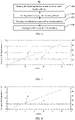
- FIG. 6 is a flow chart showing a battery bending test method 60 according to one embodiment of the present application using a battery bending test system 100 provided in the embodiments of the present application as shown in FIGS. 1 to 5 .
- step 601 the battery bending test system 100 is provided to bear the fastening device 100 by means of the load-bearing device 300 having the reference surface 301 bearing the fastening device 100.
- the battery 500 is held by the fastening device 100 of the battery bending test system 100. Specifically, the battery 500 is placed on the second surface 101b of the first plate element 101.
- the third rod-shaped element 113 may be rotated to drive the second plate element 103 to move in the direction towards the first plate element 101 along the first rod-shaped element 107 to hold the first portion 501 of the battery 500 between the third surface 103a of the second plate element 103 and the second surface 101b of the first plate element 101, i.e., the battery 500 is held between an arrangement surface 101b (the second surface 101b) and an arrangement surface 103a (the third surface 103a), and the second portion 502 of the battery 500 passes out of between the first plate element 101 and the second plate element 103 to exceed the first lateral surface 101c of the battery 500 at the first distance L in the direction the first surface 500a of the battery 500 extends.
- the first distance L may be, for example, but not limited to, about 10 mm, about 20 mm, about 30 mm, about 35 mm, about 40 mm, or about 50 mm.
- the value of the first distance L may be determined according to the specific model of the battery 500 or actual situation.
- the first angle ⁇ is formed between the arrangement surface 101b (the second surface 101b) or the arrangement surface 103a (the third surface 103a) of the fastening device 100 and the reference surface 301.
- the range of the first angle ⁇ is 0° ⁇ ⁇ ⁇ 90°.
- relevant parameters of the battery 500 are acquired using the data acquisition device.
- the relevant parameters obtained for battery 500 include, for example, but not limited to, the temperature and voltage of the battery 500, and/or pressing force to which the battery is subjected. In some embodiments of the present application, any suitable parameters related to the battery 500 may also be obtained.
- the first surface 500a of the second portion 502 of the battery 500 is pressed by means of the pressing head 201 of the pressing device 200 to bend the battery 500.
- the pressing head 201 can be configured to press the first surface 500a of the second portion 502 in the first direction X perpendicular to the reference surface 301 to bend the battery 500.
- the actuating component of the pressing device 200 is configured to lower the pressing head 201 at the predetermined speed to contact the first surface 500a of the second portion 502 of the battery 500.
- the predetermined speed can range from about 0.1 mm/min to 900 mm/min. The range of predetermined speed can be determined according to actual needs.
- the pressing head 201 may be configured to descend at a constant predetermined speed.
- the pressing head 201 may be configured to descend at a non-constant predetermined speed.
- the minimum distance D between the position where the pressing head 201 just starts pressing the battery 500 and the first lateral surface 101c may be, for example, but not limited to, about 10 mm.
- the second portion 502 of the battery 500 is pressed to a set condition.
- the set condition may be that a predetermined displacement is achieved by bending the battery 500, or a predetermined pressing force is achieved by squeezing the battery 500, or a predetermined voltage drop of the battery 500 is achieved.
- the predetermined displacement may be, for example, but not limited to, about 17.32 mm.
- the predetermined pressing force may be, for example, but not limited to, about 100 N.
- the predetermined voltage drop may be, for example, but not limited to, about 50 mv.
- the predetermined displacement, pressing force and voltage drop can be set according to the model of the battery 500 and actual needs.
- the pressing device 200 may be configured to press the first surface 500a of the second portion 502 at a speed of about 180 mm/min to 600 mm/min.
- the pressing head 200 is ceased from pressing. If the battery 500 does not catch fire or explode when the set condition is met, the battery can be determined to be qualified. Otherwise, if the battery 500 catches fire or explodes, the battery is determined to be unqualified.
- the third rod-shaped element 113 may be rotated in a reverse direction to drive the second plate element 103 to move in a direction away from the first plate element 101 along the first rod-shaped element 107.
- the battery 500 held between the first plate element 101 and the second plate element 103 is disconnected.
- the battery bending test method 60 provided in the embodiment of the present application can simulate the common bending conditions of the battery 500 during the end-use process, under which the bending test on the battery 500 is carried out. Relative movement between the battery 500 and the fastening device 100 can also be avoided during the testing process, thereby ensuring that the battery bending test is carried out effectively and smoothly. Meanwhile, the arrangement of forming the first angle ⁇ between the first surface 101a of the first plate element of the fastening device 100 and the reference surface 301 enables the pressing device 200 more conveniently press the battery 500 to any desired angle. Furthermore, different set conditions can be defined according to the specific models of different batteries 500 and actual requirements to carry out reasonable and more flexible bending test on multiple types of batteries.
- the battery bending test method 60 provided in the embodiment of the present application can precisely control the bending angle and bending morphology of the battery, so that the safety performance of different types of batteries when subjected to bending force can be evaluated more reasonably, thus meeting expectations of the safety test.
- FIG. 7 is a graph showing the variation of the parameters of a battery I with time obtained by means of the battery bending test method according to one embodiment of the present application.
- FIG. 8 is a graph showing the variation of the parameters of a battery II with time obtained by means of the battery bending test method according to one embodiment of the present application.
- Battery I and battery II of the same model with a width of about 26 mm and a thickness of about 40 mm are provided, and the initial voltage thereof is measured to be about 4.3 v.
- Battery I and battery II are held in the fastening device 100.
- Second portions 502 of both battery I and battery II go beyond the first lateral surface 101c of the respective fastening device where battery I and battery II are located at a first distance L of about 20 mm in a direction the first surface 500a of each battery extends, i.e. the Y direction.
- the pressing head 201 is brought into contact with the first surfaces 500a of the second portions 502 of battery I and battery II by lowering the pressing device 200 at a predetermined constant speed of about 20 mm/min.
- the pressing head 201 descends to press at the very beginning the respective first surface 500a of the second portion 502 of battery I and battery II, the minimum distance D along the Y direction between the position where the pressing head 201 just starts pressing battery I and battery II and the first lateral surface 101c of respective fastening device where each battery is located is about 10 mm.
- the pressing head 201 presses battery I and battery II to a predetermined displacement of about 17.5 mm at a speed of 6 mm/min.
- the displacement and voltage of battery I and battery II during the testing process are collected with the data acquisition device.
- the curve of the displacement of battery I changing over time is designated as curve I
- the curve of the voltage of battery I changing over time is designated as curve II.
- the curve of the displacement of battery II changing over time is designated as curve I
- the curve of the voltage of battery II changing over time is designated as curve II.
- the battery test method provided by the present application can set the test conditions to be accorded with the actual conditions according to the characteristics of the battery itself to carry out reasonable bending test on the battery.
- said method provided by the application realizes a more reasonable identification of internal defects and risks of the battery, thus meeting the expectations of safety testing, and having a wide range of applications.
Landscapes
- Chemical & Material Sciences (AREA)
- Physics & Mathematics (AREA)
- General Physics & Mathematics (AREA)
- Immunology (AREA)
- Analytical Chemistry (AREA)
- Biochemistry (AREA)
- General Health & Medical Sciences (AREA)
- Life Sciences & Earth Sciences (AREA)
- Health & Medical Sciences (AREA)
- Pathology (AREA)
- Engineering & Computer Science (AREA)
- Manufacturing & Machinery (AREA)
- Chemical Kinetics & Catalysis (AREA)
- Electrochemistry (AREA)
- General Chemical & Material Sciences (AREA)
- Investigating Strength Of Materials By Application Of Mechanical Stress (AREA)
- Secondary Cells (AREA)
Abstract
Description
- The embodiments of the present application relate to the field of batteries, and in particular, to a battery bending test system and method.
- Batteries are extensively used in various electronic products and electric vehicles. However, bending or folding may occur to batteries in practical applications. For example, upon dismantlement and replacement, a battery can only be disconnected with a hard pull as it is firmly attached to the battery compartment. At this time, the battery is subjected to the bending force. In another example, when the device that holds the battery is subjected to the bending force, the battery inside the device is not immune to the bending force. Such bending conditions as described may lead to safety hazards with batteries.
- Therefore, there is a need in the industry for a feasible battery bending test system and method to evaluate the possible safety risks caused by battery bending conditions.
- One of the objects of the embodiments of the present application is to provide a battery bending test system and method, which can simulate a reasonable battery bending condition, thereby realizing a reasonable evaluation of the safety performance of the battery when the battery is subjected to a bending force.
- A battery bending test system according to one embodiment of the present application, includes: a fastening device having an arrangement surface configured to hold the battery; a pressing device configured to press the battery to bend; and a load-bearing device configured to bear the fastening device, the load-bearing device having a reference surface for bearing the fastening device, wherein a first angle Ø is formed between the arrangement surface and the reference surface, and the range of first angle Ø is 0° < Ø < 90°.
- In some embodiments of the present application, the first angle Ø is about 30°, about 45°, or about 60°.
- In some embodiments of the present application, the pressing device includes a pressing head, which is configured to press the battery along the direction perpendicular to the reference surface.
- In some embodiments of the present application, the fastening device includes a first plate element, and a second plate element parallel to the first plate element for holding part of the battery.
- In some embodiments of the present application, the first plate element has the arrangement surface and a first lateral surface perpendicular to the arrangement surface, and the pressing head has a distance D from the first lateral surface along a direction of the arrangement surface extending, when the pressing head is configured to begin to press the battery.
- In some embodiments of the present application, the distance D is about 20 mm.
- In some embodiments of the present application, the fastening device further includes: a third plate element parallel to the first plate element and a first rod-shaped element penetrating the second plate element and connected to the first plate element and the third plate element, wherein the second plate element is located between the first plate element and the third plate element, and is movable between the first plate element and the third plate element along the first rod-shaped element.
- In some embodiments of the present application, the fastening device further includes: a second rod-shaped element penetrating the third plate element having a first end and a second end opposite to the first end; a fourth plate element connected to the first end and to the second plate element; and a third rod-shaped element connected to the second end, the third rod-shaped element being configured to rotate so that the second plate element is driven by the second rod-shaped element to move along the first rod-shaped element.
- In some embodiments of the present application, the pressing device is configured to descend at a predetermined speed to contact the battery.
- In some embodiments of the present application, the pressing device further includes a connecting element configured to be connected to the pressing head and an actuating element configured to be connected to the connecting element and to control displacement and pressing force of the pressing head.
- In some embodiments of the present application, the load-bearing device includes an angular adjustment element configured to be connected to the fastening device and including a bearing surface bearing the fastening device, the bearing surface being parallel to the arrangement surface of the fastening device.
- In some embodiments of the present application, the angular adjustment element is configured to connect to the reference surface.
- In some embodiments of the present application, the load-bearing device includes a base connected to the angular adjustment element.
- In some embodiments of the present application, a data acquisition device is further included for collecting battery parameters of the battery to judge the safety performance of the battery.
- A battery bending test method according to an alternative embodiment of the present application includes bearing the fastening device by means of a load-bearing device, the load-bearing device having a reference surface bearing the fastening device; holding the battery by means of the fastening device, the fastening device having an arrangement surface configured to hold the battery, wherein a first angle Ø is formed between the arrangement surface and the reference surface, the range of the first angle Ø being 0° < Ø < 90°; pressing the battery to bend by means of a pressing device; and squeezing the battery to a set condition.
- The battery bending test system and method provided by the embodiments of the application can precisely control the bending angle and bending morphology of the battery, reasonably evaluate the safety performance of the battery when the battery is subjected to the bending force, thus meeting expectations of the safety test.
- The drawings necessary to describe embodiments of the present application or the existing art will be briefly described below to facilitate the description of embodiments of the application. It is apparent that the drawings described below only represent part of embodiments of the present application. It requires no inventive effort for a person skilled in the art to obtain the drawings of other embodiments according to the structures illustrated in the described drawings.
-
FIG. 1a is a schematic perspective view showing a battery bending test system according to one embodiment of the present application; -
FIG. 1b is a top view showing the battery along a Z direction of the battery bending test system of the embodiment shown inFIG. 1a ; -
FIG. 2 is a schematic lateral view showing the battery bending test system of the embodiment shown inFIG. 1a , which illustrates a state of the battery bending test system without holding the battery; -
FIG. 3 is a schematic lateral view showing the battery bending test system of the embodiment shown inFIG. 1a , which illustrates a state of the battery bending test system when holding the battery; -
FIG. 4 is a schematic enlargement view of portion A-A of the battery bending test system of the embodiment shown inFIG. 3 ; -
FIG. 5 is a schematic perspective view showing a fastening device of the battery bending test system of the embodiment shown inFIG. 1a ; -
FIG. 6 is a flow chart showing the battery bending test method according to one embodiment of the present application; -
FIG. 7 is a graph showing the variation of parameters of a battery I with time obtained by using the battery bending test method according to one embodiment of the present application; and -
FIG. 8 is a graph showing the variation of parameters of a battery II with time obtained by using the battery bending test method according to one embodiment of the present application. - Embodiments of the present application will be described in detail below. Identical or similar components and components having identical or similar functions are designated by similar reference numerals throughout the description of the present application. Embodiments described herein with regard to the drawings are illustrative and diagrammatic, and are intended to provide a basic understanding of the present application. Embodiments of the present application should not be interpreted as limitations to the present application.
- Relative wordings such as "central," "longitudinal," "lateral," "front," "rear," "right," "left," "internal," "external," "lower," "higher," "horizontal," "vertical," "above," "below," "top," "bottom," and derivatives thereof (such as "horizontally," "downward," and "upward") in the present description, unless specifically specified or defined, should be interpreted as references to directions described in the discussion or depicted in the drawings. These relative wordings are used merely for the convenience of description, and do not require the present application to be constructed or applied in a particular direction.
- As used herein, the terms "about," "approximately," "substantially," "substantively," and "similar" are used to describe and illustrate minor variations. When used in conjunction with an event or situation, the terms may refer to instances illustrating precisely or extremely closely how the event or situation occurs. For example, when used in conjunction with values, a term may refer to a range of variation less than or equal to ±10% of the value, such as less than or equal to ±5%, less than or equal to ±4%, less than or equal to ±3%, less than or equal to ±2%, less than or equal to ±1%, less than or equal to ±0.5%, less than or equal to ±0.1%, or less than or equal to ±0.05%. For example, if the difference between two values is less than or equal to ±10% of the average of the values (e.g., less than or equal to ±5%, less than or equal to ±4%, less than or equal to ±3%, less than or equal to ±2%, less than or equal to ±1%, less than or equal to ±0.5%, less than or equal to ±0.1%, or less than or equal to ±0.05%), the two values are considered to be "substantially" the same.
- Further, for the convenience of description, "first," "second," "third," and the like may be used herein to distinguish different components of one figure or a series of figures. The terms "first," "second," "third," and the like are not intended to describe corresponding components.
- Unless specifically specified or limited, the wordings "provide," "connect," "couple," "fix," and similar thereto are used extensively in the present application, and a person skilled in the art may, depending on the specific circumstances, understand the described wordings as, for example, fixed connection, detachable connection, or integrated connection; it can also be understood as mechanical connection or electrical connection; or as direct connection or indirect connection through an intermediary structure; or as internal communication between two components.
- In the detailed description of embodiments and in the claims, a list of items following the terms "a single one of," "one of," "one kind of," or other similar terms may mean any one of the listed items. For example, if items A and B are listed, the phrase "a single one of A and B" means only A or only B. In another example, if items A, B, and C are listed, the phrase "a single one of A, B, and C" means only A; only B; or only C. Item A may include a single element or multiple elements. Item B may include a single element or multiple elements. Item C may include a single element or multiple elements.
- In the detailed description of embodiments and in the claims, a list of items following the terms "at least a single one of," "at least one of," "at least one kind of," or other similar terms may mean any combination of the listed items. For example, if items A and B are listed, the phrase "at least a single one of A and B" means only A; only B; or A and B. In another example, if items A, B, and C are listed, the phrase "at least a single one of A, B, and C" means only A; or only B; only C; A and B (excluding C); A and C (excluding B); B and C (excluding A); or all of A, B and C. Item A may include a single element or multiple elements. Item B may include a single element or multiple elements. Item C may include a single element or multiple elements.
- The General Technical Requirement of Lithium-ion Cells for Wireless Headset proposes a method of bending batteries, which requires an operating temperature of 20±5 degrees Celsius. The battery may be a cuboid having four edges extending in a length direction and four edges extending in a width direction, wherein a first edge and a second edge extend in the length direction, a third edge and a fourth edge extend in the width direction, and the third edge and the fourth edge are both located between the first edge and the second edge. First, the battery to be tested is fully charged according to manufacturer instructions for battery. Then, the battery is held loosely between two clamps of a testing machine, one of the clamp being movable to bend the battery. Next, the first edge, the second edge, the third edge and the fourth edge of the battery are bent to and fro up to 250 times at a frequency of 0.5 Hz. The battery can be bent using the device at an angle ranging from 45 degrees to 60 degrees.
- However, it is not common in the battery exposed to repeated bending of high frequency in practical applications. Therefore, the described test method does not accurately and properly simulate a common condition when the battery is subjected to bending force, and cannot reasonably evaluate the safety performance in practical applications, thus failing to meet expectations of the safety test.
- Another method is further provided by the existing art. Two metal blocks are placed horizontally, on which Teflon tapes are applied; the battery is tightly wrapped with Teflon bands followed by being placed between the two metal blocks to ensure that the battery does not slide between the blocks. Then, the battery is pressed vertically downward by using a pressing head.
- However, the applicant found that the battery clamped with metal blocks applied with Teflon bands could not be held securely. During the practical testing process, the battery and the metal blocks slide over each other easily, and thus the test cannot run smoothly. Moreover, the contact edges between the metal blocks and the battery are seamed edges that are likely to render the battery bearing a shear force, which does not conform to the practical condition of the battery. In addition, because the battery is pressed downward along a direction perpendicular to the horizontal plane according to the existing test methods, the control over the battery only provides a bending angle of a small range from about 45 degrees to 60 degrees. If a greater range of the bending angle is desired to achieve, such as about 0 degree to 90 degrees, or about 0 degree to 120 degrees, or about 0 degree to 180 degrees, it is difficult to attain with existing test methods or systems. Furthermore, the accurate control over the bending angle and bending morphology of the battery is not achievable with two described methods.
- In view of the above, the embodiments of the present application provide a novel battery bending test system and method by which the battery is bendable to a predetermined angle, or subjected to a predetermined pressure, or can achieve a predetermined displacement, so that precise control over the bending angle, displacement of the battery, and pressure exerted thereon are achieved to effectively and reasonably evaluate the safety performance of the battery based on a feasible battery bending test. In addition, by virtue of the system provided by the embodiments of the application, the battery can be firmly held to prevent the battery and the fastening device from sliding over each other during the testing process, and thus the test can be conducted more conveniently and efficiently. Further, by means of the system provided by the embodiments of the present application, the battery can bend at an angle ranging from about 0 degree to 180 degrees instead of being limited to about 45 degrees to 60 degrees.
-
FIG. 1 is a schematic perspective view showing a batterybending test system 10 according to one embodiment of the present application.FIG. 1b is a top view showing the battery along a Z direction of the batterybending test system 10 of the embodiment shown inFIG. 1a .FIG. 2 is a schematic lateral view showing the batterybending test system 10 of the embodiment shown inFIG. 1a , which illustrates a state of the batterybending test system 10 without holding the battery.FIG. 3 is a schematic lateral view showing the batterybending test system 10 of the embodiment shown inFIG. 1a , which illustrates a state of the batterybending test system 10 when holding the battery.FIG. 4 is a schematic enlargement view of portion A-A of the batterybending test system 10 of the embodiment shown inFIG. 3 .FIG. 5 is a schematic perspective view showing the fastening device of the batterybending test system 10 of the embodiment shown inFIG. 1a . As shown inFIGS. 1a to 5 , the batterybending test system 10 according to one embodiment of the present application includes afastening device 100, apressing device 200, a load-bearing device 300, anangular adjustment element 400 and abattery 500. - In one embodiment, the
fastening device 100 may be configured to hold thebattery 500. Thefastening device 100 may include afirst plate element 101, asecond plate element 103, athird plate element 105, a first rod-shapedelement 107, a second rod-shapedelement 109, afourth plate element 111, and a third rod-shapedelement 113. The material of thefirst plate element 101, thesecond plate element 103, thethird plate element 105, the first rod-shapedmember 107, the second rod-shapedelement 109, thefourth plate element 111, and the third rod-shapedelement 113 may be metallic or nonmetallic material having proper hardness. - In one embodiment, the
first plate element 101 may be configured to be mounted on areference surface 301 of the load-bearing device 300 by means of theangular adjustment element 400. In other embodiments of the present application, thefirst plate element 101 may be configured to be mounted on thereference surface 301 of the load-bearing device 300 in any suitable manner. Thefirst plate element 101 includes afirst surface 101a and asecond surface 101b opposite to thefirst surface 101a, and a firstlateral surface 101c perpendicular to and located between thefirst surface 101a and thesecond surface 101b. Thesecond surface 101b configured to hold thebattery 500 may be referred to in this application as an arrangement surface. Thefirst surface 101a of thefirst plate element 101 is provided on theangular adjustment element 400. The intersection of thesecond surface 101b and the firstlateral surface 101c may be chamfered to prevent the shear force created by said intersection acting upon thebattery 500 when thepressing device 200 presses thebattery 500. Thefirst plate element 101 may be connected to theangular adjustment element 400 viabolts 101d and to the first rod-shapedelement 107 viabolts 101e. In other embodiments of the present application, thefirst plate element 101 may be configured to be connected to theangular adjustment element 400 and the first rod-shapedelement 107 in any suitable manner. - In one embodiment, the
battery 500 has afirst portion 501 positioned on thesecond surface 101b of thefirst plate element 101, and asecond portion 502 extending from a plane where the firstlateral surface 101c is located as the starting point in a direction the arrangement surface extends, i.e. a Y direction. Thebattery 500 has afirst surface 500a and asecond surface 500b opposite to thefirst surface 500a, and both thefirst portion 501 and the second portion have thefirst surface 500a and thesecond surface 500b. Thefastening device 100 is configured to hold thefirst surface 500a and thesecond surface 500b of thefirst portion 501, and expose thefirst surface 500a and thesecond surface 500b of thesecond portion 502 of thebattery 500 so that thepressing device 200 can press thesecond portion 502 of thebattery 500. Referring toFIG. 1b , the left side of a dashed line M inFIG. 1b is thefirst portion 501 clamped in thefastening device 100, and the right side of the dashed line M is thesecond portion 502. When thebattery 500 is held between thefirst plate element 101 and thesecond plate element 103, thefirst surface 500a of thebattery 500 intersects perpendicularly with the firstlateral surface 101c, and thefirst surface 500a of thebattery 500 is parallel to thefirst surface 101a and thesecond surface 101b of thefirst plate element 101. Thesecond portion 502 of thebattery 500 passes out of between thefirst plate element 101 and thesecond plate element 103 and extends at a first distance L from a plane where the firstlateral surface 101c is located as the starting point in a direction thefirst surface 500a of the battery extends. The first distance L may be, for example, but not limited to, about 10 mm, about 20 mm, about 30 mm, about 35 mm, about 40 mm, or about 50 mm. The value of the first distance L may be determined according to the specific model of thebattery 500 or actual situation. Thebattery 500 may be substantially a cuboid having afirst edge 500c and asecond edge 500d parallel to thefirst edge 500c, and athird edge 500e and afourth edge 500f perpendicularly intersecting thesecond edge 500d and thefirst edge 500c in a plane viewed from a Z direction. The Z direction is perpendicular to thefirst surface 500a of thebattery 500. Thesecond portion 502 is a portion of the corner where the point of intersection of thethird edge 500e and thesecond edge 500d is located. In other embodiments of the present application, thesecond portion 502 may be a portion of the corner where the point of intersection of any two of thefirst edge 500c, thesecond edge 500d, thethird edge 500e, and thefourth edge 500f is located. In other embodiments of the present application, thebattery 500 may be of any shape, and thesecond portion 502 of thebattery 500 may be any portion of thebattery 500. - In one embodiment, the
second plate element 103 is parallel to thefirst plate element 101. Thesecond plate element 103 includes athird surface 103a and afourth surface 103b opposite to thethird surface 103a, and a secondlateral surface 103c perpendicular to and located between thethird surface 103a and thefourth surface 103b. Thethird surface 103a configured to hold thebattery 500 may be referred to as the arrangement surface in the present application. Thesecond plate element 103 includes a throughhole 103e passing through said second plate element. The throughhole 103e may receive the first rod-shapedelement 107 such that thesecond plate element 103 is movable along the first rod-shapedelement 107. In other embodiments of the present application, thesecond plate element 103 may be configured to receive the first rod-shapedelement 107 in any suitable manner. Thesecond plate element 103 may be moved along the first rod-shapedelement 107 in a direction towards thefirst plate element 101 so that thefirst portion 501 of thebattery 500 is held between thefirst plate element 101 and thesecond plate element 103. Alternatively, thesecond plate element 103 may be moved in a direction away from the first rod-shapedelement 107 so that thefirst portion 501 of thebattery 500 held between thefirst plate element 101 and thesecond plate element 103 is disconnected from thefastening device 100. When thebattery 500 is held between thefirst plate element 101 and thesecond plate element 103, thefirst surface 500a of thebattery 500 intersects perpendicularly with the firstlateral surface 103c of thesecond plate element 103, and is parallel to thethird surface 103a and thefourth surface 103b of thesecond plate element 103. The intersection of thethird surface 103a and the secondlateral surface 103c of the second plate element may be chamfered to prevent the shear force created by said intersection acting upon thebattery 500 when thepressing device 200 presses thebattery 500. - In one embodiment, the
third plate element 105 is parallel to thefirst plate element 101 and thesecond plate element 103. Thethird plate element 105 includes a throughhole 105a passing through said third plate element. The throughhole 105a may receive the second rod-shapedelement 109 so that the second rod-shapedelement 109 can drive thesecond plate element 103 to move along the first rod-shapedelement 107. Thethird plate element 105 may be connected to the first rod-shapedelement 107 viabolts 105b. - In one embodiment, the first rod-shaped
element 107 may be configured to penetrate thesecond plate element 103, which is connected to thefirst plate element 101 viabolts 101e and to thethird plate element 105 viabolts 105b. The first rod-shapedelement 107 is fixed between thefirst plate element 101 and thesecond plate element 103. - In one embodiment, the
second plate element 109 may be configured to penetrate thethird plate element 105. The second rod-shapedelement 109 has afirst end 109a, and asecond end 109b opposite to thefirst end 109a. Thefirst end 109a may be configured to be fixed in thefourth plate element 111. Thefourth plate element 111 is connected to thesecond plate element 103 viabolts 111a, whereby the second rod-shapedelement 109 fixed in thefourth plate element 111 can drive thesecond plate element 103 to move. Thesecond end 109b may be configured to be connected to thethird plate element 113. - In one embodiment, the
fourth plate element 111 may be configured to receive and fix thefirst end 109a of the second rod-shapedelement 109 and may be connected to thesecond plate element 103 viabolts 111a. In other embodiments of the present application, thefourth plate element 111 may fix thefirst end 109a and be connected to thesecond plate element 103 in any suitable manner. When the second rod-shapedelement 109 moves in a direction towards thefirst plate element 101, thefourth plate element 111 moves with the second rod-shapedelement 109 in the direction towards thefirst plate element 101 whereby to push thesecond plate element 103 to move in the direction towards thefirst plate element 101 along with the first rod-shapedelement 107. When the second rod-shapedelement 109 moves in a direction away from thefirst plate element 101, thefourth plate element 111 moves with the second rod-shapedelement 109 in the direction away from thefirst plate element 101 whereby to drive thesecond plate element 103 to move in the direction away from thefirst plate element 101 along with the first rod-shapedelement 107. - In one embodiment, the third rod-shaped
element 113 may be configured to be connected to thesecond end 109b of the second rod-shapedelement 109. The third rod-shapedelement 113 may be configured to rotate about in a direction that the body of the second rod-shapedelement 109 extends, and thereby the second rod-shapedelement 109 is movable through the throughhole 105a of thethird plate element 105, so that the second rod-shapedelement 109 can be moved in the direction towards or away from thefirst plate element 101 to drive thesecond plate element 103 to move in the direction towards or away from thefirst plate element 101 along with the first rod-shapedelement 107. - In one embodiment, the
pressing device 200 may be configured to press thefirst surface 500a of thesecond portion 502 of thebattery 500 to bend thebattery 500. Thepressing device 200 includes an actuating element (not shown), apressing head 201 and a connectingelement 203. - In one embodiment, the actuating element (not shown) may be configured to connect to the connecting
element 203. The actuating element can control the displacement of thepressing head 201 and the pressing force exerted on thebattery 500. The actuating element may be configured to ensure that thepressing head 201 presses thebattery 500 to the set condition. The set condition may be that a predetermined displacement is achieved by bending thebattery 500, or a predetermined pressing force is achieved by pressing thebattery 500, or a predetermined voltage drop of thebattery 500 is achieved. The predetermined displacement may be, for example, but not limited to, about 17.32 mm. The predetermined displacement may be a displacement of thebattery 500 in a first direction X. The first direction X is perpendicular to and towards thereference surface 301. The predetermined pressing force may be, for example, but not limited to, about 100 N. The predetermined voltage drop may be, for example, but not limited to, about 50 mv. The predetermined displacement, pressing force and voltage drop can be set according to the model of thebattery 500 and actual needs. The actuating element may be configured to enable thepressing head 201 to press thefirst surface 500a of thesecond portion 502 of thebattery 500 at a speed of about 180 mm/min to 600 mm/min. When the displacement, pressing force or voltage drop of thebattery 500 is measured to reach the predetermined value, the actuating element may cause thepressing head 201 to cease from pressing. The actuating element may be configured to ensure the displacement of thepressing head 201 and the pressing force with a tolerance of ±1%. The actuating element may be connected to the connectingelement 203 in any suitable manner or directly to thepressing head 201. The actuating element may be configured to press the battery to bend to a predetermined angle, or to subject to a predetermined pressure, or to achieve a predetermined displacement by means of thepressing head 201, so that precise control over the bending angle, displacement of thebattery 500, and pressure exerted thereon are achieved to effectively and reasonably evaluate the safety performance of the battery based on a feasible battery bending test. - In one embodiment, the
pressing head 201 may be configured to descend at a predetermined speed to contact thefirst surface 500a of thesecond portion 502 of thebattery 500. Thepressing head 201 may be configured to press thefirst surface 500a of thesecond portion 502 along the first direction X perpendicular to thereference surface 301 of the load-bearing device 300 to bend thebattery 500. In the direction thefirst surface 500a of thebattery 500 extends, i.e., the Y direction shown inFIGS. 3 and4 , at the very beginning thepressing head 201 descends to press thebattery 500, there is a second distance D between the position where thepressing head 201 just starts pressing thebattery 500 and the firstlateral surface 101c to prevent thepressing head 201 from contacting thefastening device 100 during subsequent pressing of thebattery 500. The second distance D may be, for example, but not limited to, about 10 mm, about 15 mm, or about 20 mm. When thepressing head 201 presses thebattery 500, thepressing head 201 moves on thesurface 500b of thebattery 500 in a direction towards the firstlateral surface 101c. Therefore, a minimum distance D is reserved to provide space for movement of thepressing head 201 to prevent thepressing head 201 from touching thefastening device 100. The value of the minimum distance D may be determined according to the specific model of thebattery 500 or actual needs. - In one embodiment, the material of the
pressing head 201 may be S136. The material of thepressing head 201 may be any material having a suitable hardness to press thebattery 500. - In one embodiment, the connecting
element 203 may be configured to connect to thepressing head 201. The connectingelement 203 may be a connecting shaft. The material of the connectingelement 203 may be S136. The diameter of the connectingelement 203 may be, for example, but not limited to, about 30 mm, about 40 mm, or about 50 mm. The material of the connectingelement 203 may possess suitable hardness to connect thepressing head 201 with the actuating element. The connectingelement 203 may be provided with apin 203a. Thepressing head 201 may be connected to the connectingelement 203 by means of thepin 203a. In other embodiments of the present application, the connectingelement 203 may be a connecting element of any suitable shape and material. - In one embodiment, the load-
bearing device 300 may be configured to bear thefastening device 100. The load-bearing device 300 has thereference surface 301 bearing theangular adjustment element 400. Thefastening device 100 is provided on thereference surface 301 of the load-bearing device 300 by means of theangular adjustment element 400 so that a first angle Ø is formed between thefirst surface 101a and thesecond surface 101b of thefirst plate element 101 of thefastening device 100 and thereference surface 301. The first angle Ø may, for example, but not limited to, in a range about 0° < Ø < 180°, about 0° < Ø < 120° or about 0° < Ø < 90°. The first angle Ø may be, for example, but not limited to, about 30°, about 45°, or about 60°. - In one embodiment, the load-
bearing device 300 may include abase 301. Theangular adjustment element 400 may be connected to thebase 301 byscrews 301a. The load-bearing device 300 may also include a fixingbase 303 configured to be connected to thebase 301. The base 301 can be connected to the fixing base 302 byscrews 301b. In embodiments of the present application, thebase 301 and the fixing base 302 may be connected in any suitable manner. - In one embodiment, the battery
bending test system 10 may also include atest platform 600. Thetest platform 600 may be configured to bear the fixingbase 303. The fixedbase 303 can be connected to thetest platform 600 by means of thescrews 303a and fixingelements 700. The fixingelements 700 may be L-shaped, which may securely connect thetest platform 600 to the fixingbase 303. In other embodiments of the present application, the fixingelements 700 may be of any suitable shape to fix the fixingbase 303 to thetest platform 600. In embodiments of the present application, the fixingbase 303 and thetest platform 600 may be connected in any suitable manner. - In one embodiment, the
angular adjustment element 400 may be configured to connect to thefastening device 100. Theangular adjustment element 400 includes abearing surface 401 bearing thefastening device 100. Thefirst plate element 101 may be connected to theangular adjustment element 400 viabolts 101d. Thefirst surface 101a of thefirst plate element 101 is provided on and parallel to thebearing surface 401. Thus, the included angle ∂ between thebearing surface 401 and thereference surface 301 is equal to the first angle Ø between thefirst surface 101a or thesecond surface 101b of thefirst plate element 101 and thereference surface 301. Therefore, theangular adjustment element 400 having different included angles ∂ can be provided to form the first angle Ø of different degrees between thefirst surface 101a and thesecond surface 101b of thefirst plate element 101 and thereference surface 301 of the load-bearing device 300, so that thepressing device 200 can bend thebattery 500 at a convenient and suitable angle θ and to any suitable angle ranging, for example, but not limited to about 0° ≤ θ ≤ 180° , about 0° ≤ θ ≤ 120°, about 0° ≤ Ø ≤ 90°, about 0° ≤ Ø ≤ 60°, or about 0° ≤ Ø ≤ 45°. - In some embodiments of the present application, the battery
bending test system 10 further includes a data acquisition device (not shown). The data acquisition device is used to collect the battery parameters of thebattery 500 to judge the safety performance of said battery. The battery parameters include various parameters that may indicate the safety performance of thebattery 500, such as, but not limited to, temperature, voltage, displacement, and pressing force to which thebattery 500 is subjected. If thebattery 500 catches fire or explodes during testing, the temperature of thebattery 500 will rise rapidly to a higher temperature and the voltage will drop to about 0 V. If thebattery 500 does not catch fire or explode during testing, the temperature and voltage of thebattery 500 will not change significantly. - The battery
bending test system 10 provided by the embodiments of the present application can firmly hold thebattery 500 between thefirst plate element 101 and thesecond plate element 103 to prevent thebattery 500 from moving during the testing process, and thefirst plate element 101 and thesecond plate element 103 do not exert shear force on thebattery 500. In addition, the first angle Ø is formed between thesecond surface 101b of thefirst plate element 101 of thefastening device 100 holding thebattery 500 and thereference surface 301 by providing theangular adjustment element 400, thus, thepressing device 200 can conveniently press thebattery 500 to bend at any desired angle θ. The bending angle θ, not being limited to a range of only about 45 degrees to 60 degrees in the existing art, can reach a range of about 0 degree to 180 degrees. Therefore, the batterybending test system 10 provided in the embodiments of the present application can accurately and appropriately simulate the common conditions when the battery is subjected to the bending force, thus meeting expectations of the safety test. -
FIG. 6 is a flow chart showing a batterybending test method 60 according to one embodiment of the present application using a batterybending test system 100 provided in the embodiments of the present application as shown inFIGS. 1 to 5 . - According to the embodiment shown in
FIG. 6 , instep 601, the batterybending test system 100 is provided to bear thefastening device 100 by means of the load-bearing device 300 having thereference surface 301 bearing thefastening device 100. - Then, in
step 602, thebattery 500 is held by thefastening device 100 of the batterybending test system 100. Specifically, thebattery 500 is placed on thesecond surface 101b of thefirst plate element 101. Next, the third rod-shapedelement 113 may be rotated to drive thesecond plate element 103 to move in the direction towards thefirst plate element 101 along the first rod-shapedelement 107 to hold thefirst portion 501 of thebattery 500 between thethird surface 103a of thesecond plate element 103 and thesecond surface 101b of thefirst plate element 101, i.e., thebattery 500 is held between anarrangement surface 101b (thesecond surface 101b) and anarrangement surface 103a (thethird surface 103a), and thesecond portion 502 of thebattery 500 passes out of between thefirst plate element 101 and thesecond plate element 103 to exceed the firstlateral surface 101c of thebattery 500 at the first distance L in the direction thefirst surface 500a of thebattery 500 extends. The first distance L may be, for example, but not limited to, about 10 mm, about 20 mm, about 30 mm, about 35 mm, about 40 mm, or about 50 mm. The value of the first distance L may be determined according to the specific model of thebattery 500 or actual situation. The first angle Ø is formed between thearrangement surface 101b (thesecond surface 101b) or thearrangement surface 103a (thethird surface 103a) of thefastening device 100 and thereference surface 301. The range of the first angle Ø is 0° < Ø < 90°. - In one embodiment, relevant parameters of the
battery 500 are acquired using the data acquisition device. The relevant parameters obtained forbattery 500 include, for example, but not limited to, the temperature and voltage of thebattery 500, and/or pressing force to which the battery is subjected. In some embodiments of the present application, any suitable parameters related to thebattery 500 may also be obtained. - In
step 603, thefirst surface 500a of thesecond portion 502 of thebattery 500 is pressed by means of thepressing head 201 of thepressing device 200 to bend thebattery 500. Thepressing head 201 can be configured to press thefirst surface 500a of thesecond portion 502 in the first direction X perpendicular to thereference surface 301 to bend thebattery 500. In one embodiment, the actuating component of thepressing device 200 is configured to lower thepressing head 201 at the predetermined speed to contact thefirst surface 500a of thesecond portion 502 of thebattery 500. The predetermined speed can range from about 0.1 mm/min to 900 mm/min. The range of predetermined speed can be determined according to actual needs. Thepressing head 201 may be configured to descend at a constant predetermined speed. In some embodiments of the present application, thepressing head 201 may be configured to descend at a non-constant predetermined speed. When thepressing head 201 descends to press thebattery 500 at the very beginning, the minimum distance D between the position where thepressing head 201 just starts pressing thebattery 500 and the firstlateral surface 101c may be, for example, but not limited to, about 10 mm. - In step 604, the
second portion 502 of thebattery 500 is pressed to a set condition. The set condition may be that a predetermined displacement is achieved by bending thebattery 500, or a predetermined pressing force is achieved by squeezing thebattery 500, or a predetermined voltage drop of thebattery 500 is achieved. The predetermined displacement may be, for example, but not limited to, about 17.32 mm. The predetermined pressing force may be, for example, but not limited to, about 100 N. The predetermined voltage drop may be, for example, but not limited to, about 50 mv. The predetermined displacement, pressing force and voltage drop can be set according to the model of thebattery 500 and actual needs. Thepressing device 200 may be configured to press thefirst surface 500a of thesecond portion 502 at a speed of about 180 mm/min to 600 mm/min. When the displacement, pressing force or voltage drop of thebattery 500 is measured to reach the predetermined value, thepressing head 200 is ceased from pressing. If thebattery 500 does not catch fire or explode when the set condition is met, the battery can be determined to be qualified. Otherwise, if thebattery 500 catches fire or explodes, the battery is determined to be unqualified. - Subsequently, the third rod-shaped
element 113 may be rotated in a reverse direction to drive thesecond plate element 103 to move in a direction away from thefirst plate element 101 along the first rod-shapedelement 107. Thus, thebattery 500 held between thefirst plate element 101 and thesecond plate element 103 is disconnected. - Therefore, the battery
bending test method 60 provided in the embodiment of the present application can simulate the common bending conditions of thebattery 500 during the end-use process, under which the bending test on thebattery 500 is carried out. Relative movement between thebattery 500 and thefastening device 100 can also be avoided during the testing process, thereby ensuring that the battery bending test is carried out effectively and smoothly. Meanwhile, the arrangement of forming the first angle Ø between thefirst surface 101a of the first plate element of thefastening device 100 and thereference surface 301 enables thepressing device 200 more conveniently press thebattery 500 to any desired angle. Furthermore, different set conditions can be defined according to the specific models ofdifferent batteries 500 and actual requirements to carry out reasonable and more flexible bending test on multiple types of batteries. In addition, the batterybending test method 60 provided in the embodiment of the present application can precisely control the bending angle and bending morphology of the battery, so that the safety performance of different types of batteries when subjected to bending force can be evaluated more reasonably, thus meeting expectations of the safety test. -
FIG. 7 is a graph showing the variation of the parameters of a battery I with time obtained by means of the battery bending test method according to one embodiment of the present application.FIG. 8 is a graph showing the variation of the parameters of a battery II with time obtained by means of the battery bending test method according to one embodiment of the present application. - Battery I and battery II of the same model with a width of about 26 mm and a thickness of about 40 mm are provided, and the initial voltage thereof is measured to be about 4.3 v. Battery I and battery II are held in the
fastening device 100.Second portions 502 of both battery I and battery II go beyond the firstlateral surface 101c of the respective fastening device where battery I and battery II are located at a first distance L of about 20 mm in a direction thefirst surface 500a of each battery extends, i.e. the Y direction. - The
pressing head 201 is brought into contact with thefirst surfaces 500a of thesecond portions 502 of battery I and battery II by lowering thepressing device 200 at a predetermined constant speed of about 20 mm/min. When thepressing head 201 descends to press at the very beginning the respectivefirst surface 500a of thesecond portion 502 of battery I and battery II, the minimum distance D along the Y direction between the position where thepressing head 201 just starts pressing battery I and battery II and the firstlateral surface 101c of respective fastening device where each battery is located is about 10 mm. - Subsequently, the
pressing head 201 presses battery I and battery II to a predetermined displacement of about 17.5 mm at a speed of 6 mm/min. - The displacement and voltage of battery I and battery II during the testing process are collected with the data acquisition device.
- In
FIG. 7 , the curve of the displacement of battery I changing over time is designated as curve I, and the curve of the voltage of battery I changing over time is designated as curve II. As can be seen fromFIG. 7 , when the displacement of battery I reaches to about 17.5 mm, the initial voltage of battery I drops rapidly from about 4.3 V to about 0 V. At this time, battery I has caught fire, so it is determined that battery I is unqualified and defective. - In
FIG. 8 , the curve of the displacement of battery II changing over time is designated as curve I, and the curve of the voltage of battery II changing over time is designated as curve II. As can be seen fromFIG. 8 , when the displacement of battery II reaches to about 17.5 mm, the initial voltage of battery II is substantially unchanged. Therefore, it can be determined that the battery II is qualified and normal. - In comparison to the battery bending test method proposed in the General Technical Requirement of Lithium-ion Cells for Wireless Headset, the battery test method provided by the present application can set the test conditions to be accorded with the actual conditions according to the characteristics of the battery itself to carry out reasonable bending test on the battery. With a precise control over the bending angle and bending morphology of the battery, said method provided by the application realizes a more reasonable identification of internal defects and risks of the battery, thus meeting the expectations of safety testing, and having a wide range of applications.
- The technical contents and features of the present application have been disclosed above, and those skilled in the art may still make various substitutions and modifications on the basis of the teachings and disclosures of the present application without departing from the spirit of the present application. Accordingly, the scope of protection of the present application is not limited to the contents disclosed in the embodiments, and should include various substitutions and modifications covered by the claims of the present application without departing from the present application.
Claims (21)
- A battery bending test system, comprising:a fastening device having an arrangement surface configured to hold the battery;a pressing device configured to press the battery to bend; anda load-bearing device configured to bear the fastening device, the load-bearing device having a reference surface bearing the fastening device, wherein a first angle Ø is formed between the arrangement surface and the reference surface, the range of the first angle Ø being 0° < Ø < 90°.
- The battery bending test system according to claim 1, wherein the first angle Ø is 30°, 45° or 60°.
- The battery bending test system according to claim 1, wherein the pressing device comprises a pressing head configured to press the battery along a direction perpendicular to the reference surface.
- The battery bending test system according to claim 3, wherein the fastening device comprises a first plate element, and a second plate element parallel to the first plate element for holding part of the battery.
- The battery bending test system according to claim 4, wherein the first plate element has an arrangement surface and a first lateral surface perpendicular to the arrangement surface, and the pressing head has a distance D from the first lateral surface in a direction of the arrangement surface extending, when the pressing head is configured to begin to press the battery.
- The battery bending test system according to claim 5, wherein the distance D is 20 mm.
- The battery bending test system according to claim 4, wherein the fastening device further comprises:a third plate element parallel to the first plate element, the second plate element being located between the first plate element and the third plate element, anda first rod-shaped element penetrating the second plate element and connected to the first plate element and the third plate element; wherein the second plate element is movable between the first plate element and the third plate element along the first rod-shaped element.
- The battery bending test system according to claim 7, wherein the fastening device further comprises:a second rod-shaped element penetrating the third plate element, the second rod-shaped element having a first end and a second end opposite to the first end;a fourth plate element connected to the first end and to the second plate element; anda third rod-shaped element connected to the second end, the third rod-shaped element being configured to rotate so that the second plate element is driven by the second rod-shaped element to move along the first rod-shaped element.
- The battery bending test system according to claim 1, wherein the load-bearing device comprises an angular adjustment element, the angular adjustment element being connected to the fastening device, and comprising a bearing surface parallel to the arrangement surface of the fastening device to bear the fastening device.
- The battery bending test system according to claim 1, further comprising a data acquisition device for collecting battery parameters of the battery to judge the safety performance of the battery.
- A battery bending test method, comprising:bearing a fastening device by means of a load-bearing device, the load-bearing device having a reference surface bearing the fastening device;holding the battery by means of the fastening device having the arrangement surface configured to hold the battery, wherein a first angle Ø is formed between the arrangement surface and the reference surface, the range of the first angle Ø being 0° < Ø < 90°;pressing the battery to bend by means of a pressing device; andpressing the battery to a set condition.
- The battery bending test method according to claim 11, wherein the set condition is to bend the battery to a predetermined displacement, or the set condition is to bend the battery to a predetermined pressing force, or the set condition is to bend the battery to a predetermined voltage drop.
- The battery bending test method according to claim 12, wherein the predetermined displacement is 17.32 mm, the predetermined pressing force is 100 N, and the predetermined voltage drop is 50 mv.
- The battery bending test method according to claim 11, wherein the first angle Ø is 30°, 45° or 60°.
- The battery bending test method according to claim 11, wherein pressing the battery to bend by means of the pressing device comprises:lowering the pressing device at a predetermined speed to contact the battery; andpressing the battery by means of the pressing device in a direction perpendicular to the reference surface.
- The battery bending test method according to claim 15, wherein the predetermined speed ranges from 0.1 mm/min to 900 mm/min.
- The battery bending test method according to claim 15, wherein the pressing device presses the battery at a speed of 180 mm/min to 600 mm/min.
- The battery bending test method according to claim 11, wherein said holding the battery by means of the fastening device comprises: a first portion of the battery being held between a first plate element and a second plate element of the fastening device, wherein the first plate element is parallel to the second plate element.
- The battery bending test method according to claim 18, wherein the first plate element has an arrangement surface and a first lateral surface perpendicular to the arrangement surface, and said holding the battery by means of the fastening device further comprises: a second portion of the battery passing out of between the first plate element and the second plate element, and extending at a first distance from a plane where the first lateral surface is located as a starting point in a direction the arrangement surface extends.
- The battery bending test method according to claim 19, said pressing the battery along the direction perpendicular to the reference surface by means of the pressing device comprising: when the pressing head is configured to just start pressing the battery, the pressing head having a distance D from the first lateral surface in a direction of the arrangement surface extending to prevent the pressing head from contacting the fastening device during the subsequent pressing.
- The battery bending test method according to claim 11, further comprising collecting battery parameters of the battery by means of a data acquisition device, the battery parameters comprising displacement and voltage of the battery, and the pressing force to which the battery is subjected.
Applications Claiming Priority (1)
| Application Number | Priority Date | Filing Date | Title |
|---|---|---|---|
| PCT/CN2020/078646 WO2021179173A1 (en) | 2020-03-10 | 2020-03-10 | Battery bending test system and battery bending test method |
Publications (3)
| Publication Number | Publication Date |
|---|---|
| EP4105634A1 true EP4105634A1 (en) | 2022-12-21 |
| EP4105634A4 EP4105634A4 (en) | 2023-04-19 |
| EP4105634B1 EP4105634B1 (en) | 2025-11-05 |
Family
ID=77670413
Family Applications (1)
| Application Number | Title | Priority Date | Filing Date |
|---|---|---|---|
| EP20924610.7A Active EP4105634B1 (en) | 2020-03-10 | 2020-03-10 | Battery bending test system and battery bending test method |
Country Status (4)
| Country | Link |
|---|---|
| US (1) | US12487157B2 (en) |
| EP (1) | EP4105634B1 (en) |
| CN (1) | CN115151804B (en) |
| WO (1) | WO2021179173A1 (en) |
Families Citing this family (4)
| Publication number | Priority date | Publication date | Assignee | Title |
|---|---|---|---|---|
| CN115151804B (en) | 2020-03-10 | 2025-02-18 | 宁德新能源科技有限公司 | Battery bending test system and battery bending test method |
| US12159980B2 (en) * | 2021-05-18 | 2024-12-03 | The United States Of America, As Represented By The Secretary Of The Navy | Precision battery grid pellet adhesion/cohesion strength tester |
| CN115343642A (en) * | 2022-07-13 | 2022-11-15 | 惠州锂威新能源科技有限公司 | Battery cell safety testing device and testing method |
| CN116989970B (en) * | 2023-09-27 | 2023-12-08 | 四川泽丰锂能新能源科技有限公司 | New energy battery pack impact resistance detection device and use method |
Family Cites Families (21)
| Publication number | Priority date | Publication date | Assignee | Title |
|---|---|---|---|---|
| US4409843A (en) * | 1982-03-11 | 1983-10-18 | Hoechst-Roussel Pharmaceuticals Inc. | Device for measuring tablet breaking force |
| DE3807065A1 (en) * | 1988-03-04 | 1989-09-07 | Fraunhofer Ges Forschung | Apparatus for the examination of fracture behaviour |
| US5022273A (en) * | 1990-06-11 | 1991-06-11 | United States Surgical Corporation | Apparatus and method for testing the bending strength of needles |
| JPH04353741A (en) * | 1991-05-30 | 1992-12-08 | Japan Atom Energy Res Inst | Method and apparatus for simultaneously measuring tensile strength and bending strength |
| US5606134A (en) * | 1995-06-21 | 1997-02-25 | Green Bay Packaging, Inc. | Score bend testing apparatus and method |
| EP0805346A1 (en) * | 1996-05-03 | 1997-11-05 | Yoshizawa Industry Inc. | Device for measuring bending strength of sheet material |
| KR101136786B1 (en) * | 2007-12-07 | 2012-04-19 | 가부시키가이샤 엔티티 도코모 | Battery testing device and battery testing method |
| JP2011209129A (en) * | 2010-03-30 | 2011-10-20 | Mitsubishi Materials Corp | Method and device for testing bending of power generation cell |
| CN201993270U (en) * | 2011-03-31 | 2011-09-28 | 鞍钢股份有限公司 | Simple clamping fixture for wire cold bending test |
| CN103674727B (en) * | 2012-11-23 | 2016-08-03 | 杭州金色能源科技有限公司 | A kind of method detecting battery bending strength and device thereof |
| US20140182392A1 (en) * | 2013-01-02 | 2014-07-03 | Apple Inc. | Apparatus and method for breakage testing of small articles |
| JP2015158442A (en) * | 2014-02-25 | 2015-09-03 | エスペック株式会社 | Battery testing apparatus |
| CN207009568U (en) * | 2017-05-17 | 2018-02-13 | 宁德新能源科技有限公司 | Naked battery core processing unit (plant) |
| CN207521469U (en) * | 2017-11-09 | 2018-06-22 | 宁德新能源科技有限公司 | For the folding lug mechanism of lithium ion battery |
| CN207472695U (en) * | 2017-11-22 | 2018-06-08 | 阿特斯阳光电力集团有限公司 | Photovoltaic cell bending strength detection device |
| CN208224320U (en) * | 2018-06-07 | 2018-12-11 | 深圳市莱恩瑞斯科技有限公司 | A kind of soft package lithium battery fixture for testing formation device |
| KR102098486B1 (en) * | 2018-08-10 | 2020-04-07 | 주식회사 포스코 | Hydrogen environment simulating apparatus |
| CN109061507A (en) * | 2018-08-31 | 2018-12-21 | 宁德新能源科技有限公司 | Battery test system and battery testing method |
| CN208721519U (en) * | 2018-09-04 | 2019-04-09 | 东莞维科电池有限公司 | A hardness measuring device |
| CN209102529U (en) * | 2018-11-13 | 2019-07-12 | 江苏宇光电源科技有限公司 | A kind of anti-extrusion bend testing apparatus of polar plate of lead acid storage battery |
| CN115151804B (en) | 2020-03-10 | 2025-02-18 | 宁德新能源科技有限公司 | Battery bending test system and battery bending test method |
-
2020
- 2020-03-10 CN CN202080097313.7A patent/CN115151804B/en active Active
- 2020-03-10 EP EP20924610.7A patent/EP4105634B1/en active Active
- 2020-03-10 WO PCT/CN2020/078646 patent/WO2021179173A1/en not_active Ceased
-
2022
- 2022-09-09 US US17/942,056 patent/US12487157B2/en active Active
Also Published As
| Publication number | Publication date |
|---|---|
| CN115151804A (en) | 2022-10-04 |
| EP4105634A4 (en) | 2023-04-19 |
| US20230003808A1 (en) | 2023-01-05 |
| CN115151804B (en) | 2025-02-18 |
| US12487157B2 (en) | 2025-12-02 |
| WO2021179173A1 (en) | 2021-09-16 |
| EP4105634B1 (en) | 2025-11-05 |
Similar Documents
| Publication | Publication Date | Title |
|---|---|---|
| US12487157B2 (en) | Battery bending test system and method | |
| EP3644390A1 (en) | Pouch manufacturing device and method, and secondary battery manufacturing method | |
| US20050014423A1 (en) | Contact arrangement with an electrical plug connection | |
| CN107069382B (en) | Vibrating pallet system for automated wire insertion | |
| WO2019105128A1 (en) | Rivet head fixture and riveting strength detection method for riveting type contact element thereof | |
| US20230087704A1 (en) | Device for testing at least one plug-in element | |
| CN207502157U (en) | Jogging switches measurement instrument | |
| JP4951355B2 (en) | Dimension measuring method and dimension measuring device for terminal fitting | |
| EP3047541B1 (en) | Electrical connector | |
| CN221819472U (en) | A bending tool for interconnection sheets on flexible solar cells | |
| CN109964110A (en) | Method for making CTOD test piece and jig for adjusting plastic strain | |
| JP5988945B2 (en) | Lead wire withstand voltage performance measuring instrument and lead wire withstand voltage performance measuring device | |
| CN114993937B (en) | Carrier Tape Peel Force Tester and Carrier Tape Peel Force Test System | |
| JP2006234428A (en) | Contact probe and inspection device | |
| CN108199084B (en) | Top and side sealing tooling and soft pack lithium battery assembly tooling | |
| KR101456424B1 (en) | Thickness Measuring Device with Novel Structure | |
| JP6731521B2 (en) | Clip test equipment | |
| US9885735B2 (en) | Sensor device that provides force versus acceleration information | |
| EP4439776A1 (en) | Pouch cell deformation inspection device and deformation inspection method using same | |
| CN206847830U (en) | Slide switch detector | |
| CN210742022U (en) | A flexible material shearing fixture and flexible material shearing equipment | |
| EP4518007A1 (en) | Welding apparatus | |
| CN108555591B (en) | Thermistor feeding molding device | |
| JP2012068063A (en) | Contact probe and charging and discharging device | |
| CN112969120A (en) | Horizontal earphone carrier |
Legal Events
| Date | Code | Title | Description |
|---|---|---|---|
| STAA | Information on the status of an ep patent application or granted ep patent |
Free format text: STATUS: THE INTERNATIONAL PUBLICATION HAS BEEN MADE |
|
| PUAI | Public reference made under article 153(3) epc to a published international application that has entered the european phase |
Free format text: ORIGINAL CODE: 0009012 |
|
| STAA | Information on the status of an ep patent application or granted ep patent |
Free format text: STATUS: REQUEST FOR EXAMINATION WAS MADE |
|
| 17P | Request for examination filed |
Effective date: 20220916 |
|
| AK | Designated contracting states |
Kind code of ref document: A1 Designated state(s): AL AT BE BG CH CY CZ DE DK EE ES FI FR GB GR HR HU IE IS IT LI LT LU LV MC MK MT NL NO PL PT RO RS SE SI SK SM TR |
|
| A4 | Supplementary search report drawn up and despatched |
Effective date: 20230317 |
|
| RIC1 | Information provided on ipc code assigned before grant |
Ipc: G01B 21/32 20060101ALI20230313BHEP Ipc: G01R 31/36 20200101ALI20230313BHEP Ipc: G01N 3/00 20060101ALI20230313BHEP Ipc: G01N 3/04 20060101ALI20230313BHEP Ipc: G01N 3/20 20060101AFI20230313BHEP |
|
| DAV | Request for validation of the european patent (deleted) | ||
| DAX | Request for extension of the european patent (deleted) | ||
| RIC1 | Information provided on ipc code assigned before grant |
Ipc: G01B 21/32 20060101ALI20250506BHEP Ipc: G01R 31/36 20200101ALI20250506BHEP Ipc: G01N 3/00 20060101ALI20250506BHEP Ipc: G01N 3/04 20060101ALI20250506BHEP Ipc: G01N 3/20 20060101AFI20250506BHEP |
|
| GRAP | Despatch of communication of intention to grant a patent |
Free format text: ORIGINAL CODE: EPIDOSNIGR1 |
|
| STAA | Information on the status of an ep patent application or granted ep patent |
Free format text: STATUS: GRANT OF PATENT IS INTENDED |
|
| INTG | Intention to grant announced |
Effective date: 20250613 |
|
| GRAS | Grant fee paid |
Free format text: ORIGINAL CODE: EPIDOSNIGR3 |
|
| GRAA | (expected) grant |
Free format text: ORIGINAL CODE: 0009210 |
|
| STAA | Information on the status of an ep patent application or granted ep patent |
Free format text: STATUS: THE PATENT HAS BEEN GRANTED |
|
| AK | Designated contracting states |
Kind code of ref document: B1 Designated state(s): AL AT BE BG CH CY CZ DE DK EE ES FI FR GB GR HR HU IE IS IT LI LT LU LV MC MK MT NL NO PL PT RO RS SE SI SK SM TR |
|
| REG | Reference to a national code |
Ref country code: CH Ref legal event code: F10 Free format text: ST27 STATUS EVENT CODE: U-0-0-F10-F00 (AS PROVIDED BY THE NATIONAL OFFICE) Effective date: 20251105 Ref country code: GB Ref legal event code: FG4D |
|
| P01 | Opt-out of the competence of the unified patent court (upc) registered |
Free format text: CASE NUMBER: UPC_APP_9264_4105634/2025 Effective date: 20251007 |
|
| REG | Reference to a national code |
Ref country code: DE Ref legal event code: R096 Ref document number: 602020061924 Country of ref document: DE |
|
| REG | Reference to a national code |
Ref country code: IE Ref legal event code: FG4D |
|
| REG | Reference to a national code |
Ref country code: NL Ref legal event code: FP |
|
| PGFP | Annual fee paid to national office [announced via postgrant information from national office to epo] |
Ref country code: NL Payment date: 20260213 Year of fee payment: 7 |
|
| PGFP | Annual fee paid to national office [announced via postgrant information from national office to epo] |
Ref country code: GB Payment date: 20260202 Year of fee payment: 7 |
|
| PG25 | Lapsed in a contracting state [announced via postgrant information from national office to epo] |
Ref country code: ES Free format text: LAPSE BECAUSE OF FAILURE TO SUBMIT A TRANSLATION OF THE DESCRIPTION OR TO PAY THE FEE WITHIN THE PRESCRIBED TIME-LIMIT Effective date: 20251105 |
|
| REG | Reference to a national code |
Ref country code: LT Ref legal event code: MG9D |
|
| PG25 | Lapsed in a contracting state [announced via postgrant information from national office to epo] |
Ref country code: NO Free format text: LAPSE BECAUSE OF FAILURE TO SUBMIT A TRANSLATION OF THE DESCRIPTION OR TO PAY THE FEE WITHIN THE PRESCRIBED TIME-LIMIT Effective date: 20260205 |
|
| PGFP | Annual fee paid to national office [announced via postgrant information from national office to epo] |
Ref country code: DE Payment date: 20260204 Year of fee payment: 7 |
|
| PG25 | Lapsed in a contracting state [announced via postgrant information from national office to epo] |
Ref country code: HR Free format text: LAPSE BECAUSE OF FAILURE TO SUBMIT A TRANSLATION OF THE DESCRIPTION OR TO PAY THE FEE WITHIN THE PRESCRIBED TIME-LIMIT Effective date: 20251105 Ref country code: FI Free format text: LAPSE BECAUSE OF FAILURE TO SUBMIT A TRANSLATION OF THE DESCRIPTION OR TO PAY THE FEE WITHIN THE PRESCRIBED TIME-LIMIT Effective date: 20251105 Ref country code: AT Free format text: LAPSE BECAUSE OF FAILURE TO SUBMIT A TRANSLATION OF THE DESCRIPTION OR TO PAY THE FEE WITHIN THE PRESCRIBED TIME-LIMIT Effective date: 20251105 |
|
| REG | Reference to a national code |
Ref country code: AT Ref legal event code: MK05 Ref document number: 1854833 Country of ref document: AT Kind code of ref document: T Effective date: 20251105 |
|
| PG25 | Lapsed in a contracting state [announced via postgrant information from national office to epo] |
Ref country code: RS Free format text: LAPSE BECAUSE OF FAILURE TO SUBMIT A TRANSLATION OF THE DESCRIPTION OR TO PAY THE FEE WITHIN THE PRESCRIBED TIME-LIMIT Effective date: 20260205 |
|
| PG25 | Lapsed in a contracting state [announced via postgrant information from national office to epo] |
Ref country code: IS Free format text: LAPSE BECAUSE OF FAILURE TO SUBMIT A TRANSLATION OF THE DESCRIPTION OR TO PAY THE FEE WITHIN THE PRESCRIBED TIME-LIMIT Effective date: 20260305 |
|
| PGFP | Annual fee paid to national office [announced via postgrant information from national office to epo] |
Ref country code: FR Payment date: 20260209 Year of fee payment: 7 |
|
| PG25 | Lapsed in a contracting state [announced via postgrant information from national office to epo] |
Ref country code: PT Free format text: LAPSE BECAUSE OF FAILURE TO SUBMIT A TRANSLATION OF THE DESCRIPTION OR TO PAY THE FEE WITHIN THE PRESCRIBED TIME-LIMIT Effective date: 20260305 |
|
| PG25 | Lapsed in a contracting state [announced via postgrant information from national office to epo] |
Ref country code: PL Free format text: LAPSE BECAUSE OF FAILURE TO SUBMIT A TRANSLATION OF THE DESCRIPTION OR TO PAY THE FEE WITHIN THE PRESCRIBED TIME-LIMIT Effective date: 20251105 |
|
| PG25 | Lapsed in a contracting state [announced via postgrant information from national office to epo] |
Ref country code: LV Free format text: LAPSE BECAUSE OF FAILURE TO SUBMIT A TRANSLATION OF THE DESCRIPTION OR TO PAY THE FEE WITHIN THE PRESCRIBED TIME-LIMIT Effective date: 20251105 |
|
| PG25 | Lapsed in a contracting state [announced via postgrant information from national office to epo] |
Ref country code: BG Free format text: LAPSE BECAUSE OF FAILURE TO SUBMIT A TRANSLATION OF THE DESCRIPTION OR TO PAY THE FEE WITHIN THE PRESCRIBED TIME-LIMIT Effective date: 20251105 |