EP4105542A1 - Pressure reducing device - Google Patents
Pressure reducing device Download PDFInfo
- Publication number
- EP4105542A1 EP4105542A1 EP21179536.4A EP21179536A EP4105542A1 EP 4105542 A1 EP4105542 A1 EP 4105542A1 EP 21179536 A EP21179536 A EP 21179536A EP 4105542 A1 EP4105542 A1 EP 4105542A1
- Authority
- EP
- European Patent Office
- Prior art keywords
- pressure
- valve
- pressure reducing
- fluid circuit
- safety relief
- Prior art date
- Legal status (The legal status is an assumption and is not a legal conclusion. Google has not performed a legal analysis and makes no representation as to the accuracy of the status listed.)
- Granted
Links
Images


Classifications
-
- F—MECHANICAL ENGINEERING; LIGHTING; HEATING; WEAPONS; BLASTING
- F17—STORING OR DISTRIBUTING GASES OR LIQUIDS
- F17C—VESSELS FOR CONTAINING OR STORING COMPRESSED, LIQUEFIED OR SOLIDIFIED GASES; FIXED-CAPACITY GAS-HOLDERS; FILLING VESSELS WITH, OR DISCHARGING FROM VESSELS, COMPRESSED, LIQUEFIED, OR SOLIDIFIED GASES
- F17C13/00—Details of vessels or of the filling or discharging of vessels
- F17C13/04—Arrangement or mounting of valves
-
- F—MECHANICAL ENGINEERING; LIGHTING; HEATING; WEAPONS; BLASTING
- F17—STORING OR DISTRIBUTING GASES OR LIQUIDS
- F17C—VESSELS FOR CONTAINING OR STORING COMPRESSED, LIQUEFIED OR SOLIDIFIED GASES; FIXED-CAPACITY GAS-HOLDERS; FILLING VESSELS WITH, OR DISCHARGING FROM VESSELS, COMPRESSED, LIQUEFIED, OR SOLIDIFIED GASES
- F17C2201/00—Vessel construction, in particular geometry, arrangement or size
- F17C2201/01—Shape
- F17C2201/0104—Shape cylindrical
- F17C2201/0119—Shape cylindrical with flat end-piece
-
- F—MECHANICAL ENGINEERING; LIGHTING; HEATING; WEAPONS; BLASTING
- F17—STORING OR DISTRIBUTING GASES OR LIQUIDS
- F17C—VESSELS FOR CONTAINING OR STORING COMPRESSED, LIQUEFIED OR SOLIDIFIED GASES; FIXED-CAPACITY GAS-HOLDERS; FILLING VESSELS WITH, OR DISCHARGING FROM VESSELS, COMPRESSED, LIQUEFIED, OR SOLIDIFIED GASES
- F17C2205/00—Vessel construction, in particular mounting arrangements, attachments or identifications means
- F17C2205/03—Fluid connections, filters, valves, closure means or other attachments
- F17C2205/0302—Fittings, valves, filters, or components in connection with the gas storage device
- F17C2205/0311—Closure means
- F17C2205/0314—Closure means breakable, e.g. with burst discs
-
- F—MECHANICAL ENGINEERING; LIGHTING; HEATING; WEAPONS; BLASTING
- F17—STORING OR DISTRIBUTING GASES OR LIQUIDS
- F17C—VESSELS FOR CONTAINING OR STORING COMPRESSED, LIQUEFIED OR SOLIDIFIED GASES; FIXED-CAPACITY GAS-HOLDERS; FILLING VESSELS WITH, OR DISCHARGING FROM VESSELS, COMPRESSED, LIQUEFIED, OR SOLIDIFIED GASES
- F17C2205/00—Vessel construction, in particular mounting arrangements, attachments or identifications means
- F17C2205/03—Fluid connections, filters, valves, closure means or other attachments
- F17C2205/0302—Fittings, valves, filters, or components in connection with the gas storage device
- F17C2205/0323—Valves
- F17C2205/0332—Safety valves or pressure relief valves
-
- F—MECHANICAL ENGINEERING; LIGHTING; HEATING; WEAPONS; BLASTING
- F17—STORING OR DISTRIBUTING GASES OR LIQUIDS
- F17C—VESSELS FOR CONTAINING OR STORING COMPRESSED, LIQUEFIED OR SOLIDIFIED GASES; FIXED-CAPACITY GAS-HOLDERS; FILLING VESSELS WITH, OR DISCHARGING FROM VESSELS, COMPRESSED, LIQUEFIED, OR SOLIDIFIED GASES
- F17C2205/00—Vessel construction, in particular mounting arrangements, attachments or identifications means
- F17C2205/03—Fluid connections, filters, valves, closure means or other attachments
- F17C2205/0302—Fittings, valves, filters, or components in connection with the gas storage device
- F17C2205/0323—Valves
- F17C2205/0335—Check-valves or non-return valves
-
- F—MECHANICAL ENGINEERING; LIGHTING; HEATING; WEAPONS; BLASTING
- F17—STORING OR DISTRIBUTING GASES OR LIQUIDS
- F17C—VESSELS FOR CONTAINING OR STORING COMPRESSED, LIQUEFIED OR SOLIDIFIED GASES; FIXED-CAPACITY GAS-HOLDERS; FILLING VESSELS WITH, OR DISCHARGING FROM VESSELS, COMPRESSED, LIQUEFIED, OR SOLIDIFIED GASES
- F17C2205/00—Vessel construction, in particular mounting arrangements, attachments or identifications means
- F17C2205/03—Fluid connections, filters, valves, closure means or other attachments
- F17C2205/0302—Fittings, valves, filters, or components in connection with the gas storage device
- F17C2205/0338—Pressure regulators
-
- F—MECHANICAL ENGINEERING; LIGHTING; HEATING; WEAPONS; BLASTING
- F17—STORING OR DISTRIBUTING GASES OR LIQUIDS
- F17C—VESSELS FOR CONTAINING OR STORING COMPRESSED, LIQUEFIED OR SOLIDIFIED GASES; FIXED-CAPACITY GAS-HOLDERS; FILLING VESSELS WITH, OR DISCHARGING FROM VESSELS, COMPRESSED, LIQUEFIED, OR SOLIDIFIED GASES
- F17C2205/00—Vessel construction, in particular mounting arrangements, attachments or identifications means
- F17C2205/03—Fluid connections, filters, valves, closure means or other attachments
- F17C2205/0302—Fittings, valves, filters, or components in connection with the gas storage device
- F17C2205/0341—Filters
-
- F—MECHANICAL ENGINEERING; LIGHTING; HEATING; WEAPONS; BLASTING
- F17—STORING OR DISTRIBUTING GASES OR LIQUIDS
- F17C—VESSELS FOR CONTAINING OR STORING COMPRESSED, LIQUEFIED OR SOLIDIFIED GASES; FIXED-CAPACITY GAS-HOLDERS; FILLING VESSELS WITH, OR DISCHARGING FROM VESSELS, COMPRESSED, LIQUEFIED, OR SOLIDIFIED GASES
- F17C2205/00—Vessel construction, in particular mounting arrangements, attachments or identifications means
- F17C2205/03—Fluid connections, filters, valves, closure means or other attachments
- F17C2205/0302—Fittings, valves, filters, or components in connection with the gas storage device
- F17C2205/0382—Constructional details of valves, regulators
- F17C2205/0385—Constructional details of valves, regulators in blocks or units
-
- F—MECHANICAL ENGINEERING; LIGHTING; HEATING; WEAPONS; BLASTING
- F17—STORING OR DISTRIBUTING GASES OR LIQUIDS
- F17C—VESSELS FOR CONTAINING OR STORING COMPRESSED, LIQUEFIED OR SOLIDIFIED GASES; FIXED-CAPACITY GAS-HOLDERS; FILLING VESSELS WITH, OR DISCHARGING FROM VESSELS, COMPRESSED, LIQUEFIED, OR SOLIDIFIED GASES
- F17C2205/00—Vessel construction, in particular mounting arrangements, attachments or identifications means
- F17C2205/03—Fluid connections, filters, valves, closure means or other attachments
- F17C2205/0388—Arrangement of valves, regulators, filters
- F17C2205/0394—Arrangement of valves, regulators, filters in direct contact with the pressure vessel
-
- F—MECHANICAL ENGINEERING; LIGHTING; HEATING; WEAPONS; BLASTING
- F17—STORING OR DISTRIBUTING GASES OR LIQUIDS
- F17C—VESSELS FOR CONTAINING OR STORING COMPRESSED, LIQUEFIED OR SOLIDIFIED GASES; FIXED-CAPACITY GAS-HOLDERS; FILLING VESSELS WITH, OR DISCHARGING FROM VESSELS, COMPRESSED, LIQUEFIED, OR SOLIDIFIED GASES
- F17C2221/00—Handled fluid, in particular type of fluid
- F17C2221/01—Pure fluids
- F17C2221/012—Hydrogen
-
- F—MECHANICAL ENGINEERING; LIGHTING; HEATING; WEAPONS; BLASTING
- F17—STORING OR DISTRIBUTING GASES OR LIQUIDS
- F17C—VESSELS FOR CONTAINING OR STORING COMPRESSED, LIQUEFIED OR SOLIDIFIED GASES; FIXED-CAPACITY GAS-HOLDERS; FILLING VESSELS WITH, OR DISCHARGING FROM VESSELS, COMPRESSED, LIQUEFIED, OR SOLIDIFIED GASES
- F17C2221/00—Handled fluid, in particular type of fluid
- F17C2221/03—Mixtures
- F17C2221/037—Containing pollutant, e.g. H2S, Cl
-
- F—MECHANICAL ENGINEERING; LIGHTING; HEATING; WEAPONS; BLASTING
- F17—STORING OR DISTRIBUTING GASES OR LIQUIDS
- F17C—VESSELS FOR CONTAINING OR STORING COMPRESSED, LIQUEFIED OR SOLIDIFIED GASES; FIXED-CAPACITY GAS-HOLDERS; FILLING VESSELS WITH, OR DISCHARGING FROM VESSELS, COMPRESSED, LIQUEFIED, OR SOLIDIFIED GASES
- F17C2223/00—Handled fluid before transfer, i.e. state of fluid when stored in the vessel or before transfer from the vessel
- F17C2223/01—Handled fluid before transfer, i.e. state of fluid when stored in the vessel or before transfer from the vessel characterised by the phase
- F17C2223/0107—Single phase
- F17C2223/0123—Single phase gaseous, e.g. CNG, GNC
-
- F—MECHANICAL ENGINEERING; LIGHTING; HEATING; WEAPONS; BLASTING
- F17—STORING OR DISTRIBUTING GASES OR LIQUIDS
- F17C—VESSELS FOR CONTAINING OR STORING COMPRESSED, LIQUEFIED OR SOLIDIFIED GASES; FIXED-CAPACITY GAS-HOLDERS; FILLING VESSELS WITH, OR DISCHARGING FROM VESSELS, COMPRESSED, LIQUEFIED, OR SOLIDIFIED GASES
- F17C2223/00—Handled fluid before transfer, i.e. state of fluid when stored in the vessel or before transfer from the vessel
- F17C2223/03—Handled fluid before transfer, i.e. state of fluid when stored in the vessel or before transfer from the vessel characterised by the pressure level
- F17C2223/036—Very high pressure (>80 bar)
-
- F—MECHANICAL ENGINEERING; LIGHTING; HEATING; WEAPONS; BLASTING
- F17—STORING OR DISTRIBUTING GASES OR LIQUIDS
- F17C—VESSELS FOR CONTAINING OR STORING COMPRESSED, LIQUEFIED OR SOLIDIFIED GASES; FIXED-CAPACITY GAS-HOLDERS; FILLING VESSELS WITH, OR DISCHARGING FROM VESSELS, COMPRESSED, LIQUEFIED, OR SOLIDIFIED GASES
- F17C2225/00—Handled fluid after transfer, i.e. state of fluid after transfer from the vessel
- F17C2225/01—Handled fluid after transfer, i.e. state of fluid after transfer from the vessel characterised by the phase
- F17C2225/0107—Single phase
- F17C2225/0123—Single phase gaseous, e.g. CNG, GNC
-
- F—MECHANICAL ENGINEERING; LIGHTING; HEATING; WEAPONS; BLASTING
- F17—STORING OR DISTRIBUTING GASES OR LIQUIDS
- F17C—VESSELS FOR CONTAINING OR STORING COMPRESSED, LIQUEFIED OR SOLIDIFIED GASES; FIXED-CAPACITY GAS-HOLDERS; FILLING VESSELS WITH, OR DISCHARGING FROM VESSELS, COMPRESSED, LIQUEFIED, OR SOLIDIFIED GASES
- F17C2225/00—Handled fluid after transfer, i.e. state of fluid after transfer from the vessel
- F17C2225/03—Handled fluid after transfer, i.e. state of fluid after transfer from the vessel characterised by the pressure level
- F17C2225/036—Very high pressure, i.e. above 80 bars
-
- F—MECHANICAL ENGINEERING; LIGHTING; HEATING; WEAPONS; BLASTING
- F17—STORING OR DISTRIBUTING GASES OR LIQUIDS
- F17C—VESSELS FOR CONTAINING OR STORING COMPRESSED, LIQUEFIED OR SOLIDIFIED GASES; FIXED-CAPACITY GAS-HOLDERS; FILLING VESSELS WITH, OR DISCHARGING FROM VESSELS, COMPRESSED, LIQUEFIED, OR SOLIDIFIED GASES
- F17C2250/00—Accessories; Control means; Indicating, measuring or monitoring of parameters
- F17C2250/06—Controlling or regulating of parameters as output values
- F17C2250/0605—Parameters
- F17C2250/0626—Pressure
-
- F—MECHANICAL ENGINEERING; LIGHTING; HEATING; WEAPONS; BLASTING
- F17—STORING OR DISTRIBUTING GASES OR LIQUIDS
- F17C—VESSELS FOR CONTAINING OR STORING COMPRESSED, LIQUEFIED OR SOLIDIFIED GASES; FIXED-CAPACITY GAS-HOLDERS; FILLING VESSELS WITH, OR DISCHARGING FROM VESSELS, COMPRESSED, LIQUEFIED, OR SOLIDIFIED GASES
- F17C2250/00—Accessories; Control means; Indicating, measuring or monitoring of parameters
- F17C2250/06—Controlling or regulating of parameters as output values
- F17C2250/0605—Parameters
- F17C2250/0636—Flow or movement of content
-
- F—MECHANICAL ENGINEERING; LIGHTING; HEATING; WEAPONS; BLASTING
- F17—STORING OR DISTRIBUTING GASES OR LIQUIDS
- F17C—VESSELS FOR CONTAINING OR STORING COMPRESSED, LIQUEFIED OR SOLIDIFIED GASES; FIXED-CAPACITY GAS-HOLDERS; FILLING VESSELS WITH, OR DISCHARGING FROM VESSELS, COMPRESSED, LIQUEFIED, OR SOLIDIFIED GASES
- F17C2260/00—Purposes of gas storage and gas handling
- F17C2260/02—Improving properties related to fluid or fluid transfer
- F17C2260/021—Avoiding over pressurising
-
- F—MECHANICAL ENGINEERING; LIGHTING; HEATING; WEAPONS; BLASTING
- F17—STORING OR DISTRIBUTING GASES OR LIQUIDS
- F17C—VESSELS FOR CONTAINING OR STORING COMPRESSED, LIQUEFIED OR SOLIDIFIED GASES; FIXED-CAPACITY GAS-HOLDERS; FILLING VESSELS WITH, OR DISCHARGING FROM VESSELS, COMPRESSED, LIQUEFIED, OR SOLIDIFIED GASES
- F17C2260/00—Purposes of gas storage and gas handling
- F17C2260/03—Dealing with losses
- F17C2260/035—Dealing with losses of fluid
- F17C2260/036—Avoiding leaks
Definitions
- the invention relates to the field of valves for compressed gas.
- the invention relates to pressure reducing devices.
- Pressure reducing devices dedicated to high pressure fluids have been used for many years already. Pressure reducing devices allow to use high pressure sources, of for example 300 bar and higher, while remaining compatible with coupled installations that require a lower pressure inlet, of for example 200 bar and lower through the use of specifically made interfaces, i.e. valve delivery port specifically coded for such lower pressures as per applicable regulation/standard.
- a fluid's pressure and volume are correlated, as when the pressure increases, the volume decreases. Therefore, pressure reducing devices make the user's tasks easier as more gas can be stored in a higher-pressure vessel while keeping its volume small. Using a pressure reducing device will allow the user to have a desired pressure for the coupled installations that are typically designed for lower pressures, even if the stored fluid has a pressure being over the coupled installation's capacity. So, pressure reducing devices increase either usage autonomy at equivalent size of vessel, or increase portability, by reducing the vessel's size and weight.
- pressure reducing devices are, for example, used in standalone cylinders, as well as bundles and trailers. This feature is concretely achieved by implementing an integrated pressure unit within the cylinder valve body (for instance, main shutoff valve, pressure regulating unit, emergency shutoff valve and safety relief device are integrated in same body), or with separate elements (main shutoff valve, pressure regulating unit, emergency shutoff valve and safety relief device are different objects) within a dedicated gas panel on the bundles, tube trailers,...
- the downstream end of the pressure reducing device may comprise an outlet valve, or it can be just a simple connection or interface.
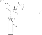
- the pressure reducing device comprises an operational fluid circuit 101 having an optional main shutoff valve 2 allowing the opening-up of the pressure reducing unit, a pressure regulating unit 3 reducing the pressure to a set desired value with a maximum pressure P A it can deliver, a safety relief device 6 opening itself in case of an excess pressure being higher than the maximum allowable pressure P A in the coupled downstream installation is present, and an outlet interface 5 that may comprise a valve, being connected to the coupled installation.
- the Safety relief device 6 is located downstream of the pressure reducing unit 3 to protect the lower pressure side of the system.
- the safety relief device 6 can for example be a safety relief valve or a bursting disc, being respectively reversible and single use.
- the safety relief device 6 is designed to open in case of an unexpected excess pressure being higher than the maximum allowable pressure in the coupled installation is being detected, this excess pressure can for example be due to a failure or malfunction of the pressure reducing unit 3.
- An outlet interface 5 can be configured in different manners, such as threaded joint, quick-connect, featuring a check-valve, a non-return valve, a shut-off valve.
- the outlet interface 5 has a determined pressure P N (e.g. 200bar) which corresponds either to its pressure capability or rating.
- P N e.g. 200bar
- an optional gas filter can be placed between the main shutoff valve 2 and the pressure reducing unit 3, but it is possible to be placed upstream of the main shutoff valve, and an optional non-return valve can be placed in the fluid circuit, downstream the emergency shutoff valve.
- the fluid contained might be a flammable medium such as hydrogen or other fluids creating dangerous and/or toxic environments, e.g. ATEX (Atmosphere Explosives).
- the safety relief device can be collected to a complimentary exhaust pipeline or equivalent, it would complicate the connection process to the installation by requiring additional setups and extra handling steps, for example extensive safety checks, relying on a procedural barrier.
- safety relief devices are mechanical components and are therefore prone to failure. Although these devices are designed to be highly reliable, malfunctions and defects should always be taken into consideration.
- the invention relates to a pressure reducing device comprising an upstream end configured to be connected to a pressurized gas source and a downstream end configured to be connected to a coupled installation and comprising:
- the invention solves the above-mentioned problems by implementing a failure safe feature on the pressure reducing device (PRD) that prevents any release of fluid to the atmosphere while requiring no external energy and no extra components such as a PLC system.
- PRD pressure reducing device
- the pressure increases in the PRD will lead to a spontaneous shutoff of the feeding flow, fully protecting the downstream coupled installation by shutting down the pressure source.
- the emergency shutoff valve will get actuated by the overpressure released through the safety relief device (SRD) in case of failure of the pressure reducing unit (PRU). So, instead of releasing the overpressure fluid to atmosphere, the invention allows to advantageously and safely shut down the gas stream.
- SRD safety relief device
- PRU pressure reducing unit
- the operational fluid circuit of the pressure reducing device may comprise a residual pressure valve.
- Having a residual pressure valve (RPV) may help the emergency shutoff valve (ESOV) engage more quickly when the SRD is open by keeping a small amount of pressure stored in the RPV.
- RPV residual pressure valve
- ESOV emergency shutoff valve
- a second variant of the invention would be that the residual pressure valve may comprise the emergency shutoff valve.
- the residual pressure valve as the emergency shutoff valve would save space as well as reduce the complexity of the fluid circuits used.
- a third variant of the invention would be that the pressure reducing valve may also comprise a non-return valve.
- a non-return valve (NRV) will allow the fluid to flow through it in only one direction. It also always maintains a positive pressure in the system, while preventing any unwanted material from inadvertently being backed into the previous components of the PRD.
- the non-return function would allow to balance pressures in case of backflow from downstream as well as keeping the emergency shutoff valve closed by stopping the backflow to come back to the ESOV.
- a fourth variant of the invention would be that a non-return valve may be comprised in the emergency shutoff valve. Having a NRV in the ESOV would also save space on the operational fluid circuit.
- a first option of the invention would be that the safety relief device comprises a bursting disc.
- a bursting disc (BD) is a sacrificial part as it has a one-time-use membrane that fails at a predetermined pressure. If the BD is opened, or more precisely burst, a simple replacement can be executed and maintenance on PRD becomes simple.
- a second option of the invention would be that the safety relief device comprises a safety relief valve.
- a safety relief valve (SRV) will reduce costs as well as remove the need to have access to extra parts (compared to the use of a BD).
- the safety relief valve is reversible, and the system could easily be reset.
- a fifth variant of the invention would be that the safety relief device and the emergency shutoff valve may be connected through a fluid connection, said connection comprising a reset valve.
- a reset valve will allow to release the pressure when the SRD has been opened and that the ESOV is closed.
- the reset valve allows a quick and easy reset of the PRD by purging the relief fluid circuit downstream of the SRV.
- the pressure reducing device may be a one-way valve.
- a PRD is used for fluid delivery only, and is for example a bundle.
- the pressure reducing device may also be a two-way valve.
- the PRD would allow both delivery and filling through either an external neutralization process for single ported valves or through implementation of a dedicated filling port, for example for standalone cylinders or bundles featuring a single valve.
- the pressure reducing device may comprise a bleeding valve.
- a bleeding valve allows minute amounts of fluid to be released in case of leak, for example from elastomeric ring seals, to avoid any pressure build up on the ESOV, which could otherwise hinder the ESOV's expected function.
- the bleeding valve could be comprised in the relief fluid circuit.
- a seventh variant of the invention would be that the relief fluid circuit comprises a flap may be leaning against the bleeding valve. When the ESOV is closed, the flap will automatically close as well to avoid any release of fluid to the atmosphere.
- a central part of the residual pressure valve comprises a first piston being mobile in a middle chamber, and the residual pressure valve has three connections:
- a middle chamber is made in the central part of the RPV for the fluid returning from the SRD to the RPV, in case the SRD is opened.
- the first piston is pushed towards the outlet valve, being the coupled installation's inlet, to close the system.
- the central part of the residual pressure valve may also comprise a second piston, the middle chamber being delimited by the first piston and the second piston, and in the open position of the safety relief device, the bleeding valve is closed by the second piston.
- the second piston would put the bleeding valve's flap in place or be pushed towards the bleeding valve in order to deny any pressure evacuation from the bleeding valve when the SRD is open.
- the invention also related to a device for storing and supplying compressed gas comprising a fluid source and a pressure reducing device comprising any of preceding characteristics.
- a fluid flows from a starting point of a fluid circuit to an end point of a circuit, passing through parts of the fluid circuits, e.g., valves. Positions may be referred to as downstream or upstream of a certain part. "Upstream” is used to describe a position on the circuit, in or before the said part with respect to the direction of the fluid flow whereas “downstream” is used to describe a position on the circuit in or after the said part with respect to the direction of the fluid flow.
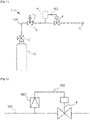
- a fluid source 12 feeds the pressure reducing device (PRD) 1, this fluid source being for example a vessel.
- the PRD 1 comprises an operational fluid circuit 101 and a relief fluid circuit 102.
- the PRD inlet can be opened by a main shutoff valve (MSOV) 2, the MSOV 2 being part of the operational fluid circuit 101.
- a pressure reducing unit (PRU) 3 is also situated on the operational fluid circuit 101, and is used as a control valve that reduces higher upstream pressure to predetermined lower constant downstream pressure.
- the PRU 3 can for example be operated by a spring set to allow a certain pressure to flow through it, the spring being preferably a "Belleville spring".
- the main shutoff valve 2 and the pressure regulating unit 3 can be provided by single valve.
- a Safety relief device (SRD) 6 is also connected to the system to detect any overpressure in the PRD 1. Such an overpressure downstream of the PRU 3 can for example be caused by a malfunctioning PRU 3, a failure of the PRU 3 or a setting error.
- the SRD 6 will open itself when an overpressure is detected (when subjected to an overpressure) and therefore, the fluid would pass through the open SRD 6.
- the relief fluid circuit 102 prevents any release of fluid outside of the PRD 1 as it is connected to an emergency shutoff valve (ESOV) 4.
- ESOV 4 is used and configured to close the system when the SRD 6 is opened, by receiving the overpressure from the relief fluid circuit 102.
- An outlet interface 5 may be placed downstream of the PRD 1 and is used to let the fluid go out of the PRD 1 and to go to a coupled installation.
- a gas filter 13 may also be added to the PRD 1, preferentially upstream of the PRU 3. Such a gas filter may be used to filter out any unwanted particles in the system, such as dirt or rust particles.
- All or some of the operational fluid circuit 101, relief fluid circuit 102, main shutoff valve (MSOV) 2, emergency shutoff valve (ESOV) 4 and outlet interface 5 may be integrated into a common body configured to be removably connected to a fluid source 2 (or separate bodies fluidly connected together).
- An overpressure is defined as a pressure being higher than the limit allowable pressure P L of the coupled installation, P L being between P A + 5% and P A + 500% and/or between P N + 5% and P N +500%, preferably +20%, P A and P N are generally comprised between 200 bar and 300 bar, depending on the coupled installation capabilities. That is to say, when the pressure downstream the pressure reducing unit 3 is abnormal (above the pressure capability P N of the outlet interface 5 and/or exceeds the maximum pressure P A of the pressure reducing unit 3 to a predetermined value such as +5% to 500% and preferably +20%) the safety relief device 6 is automatically opened, and the emergency shutoff valve 4 closed.
- the SRD 6 can, for example, be a bursting disc 601 (BD), a safety relief valve 602 (SRV), balanced bellows, or power actuated, but the SRD 6 is preferentially a BD or a SRV.
- BD bursting disc 601
- SRV safety relief valve 602
- balanced bellows or power actuated
- the SRD 6 is preferentially a BD or a SRV.
- a first embodiment is represented on [ Fig. 3 ], on which it shows a closer look at the SRD 6.
- the SRD 6 is a bursting disc (BD) 601.
- the BD 601 is a sacrificial part because it has a one-time-use membrane that fails at a predetermined pressure. If the BD 601 is burst, a simple replacement can be executed and maintenance on the PRD 1 becomes simple. In case of overpressure, the BD 601 bursts, letting the fluid flow in the relief fluid circuit 102 to the ESOV 4, said ESOV 4 closing the operational fluid circuit 101, and consequently the whole PRD 1, to avoid any overpressure going to the coupled installation.
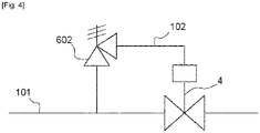
- a second embodiment is represented on [ Fig. 4 ], on which it shows a closer look at the SRD 6.
- the SRD 6 is a safety relief valve (SRV) 602.
- the SRV 602 is reversible, and the system could easily be reset. In case of overpressure, the SRV 602 opens, letting the overpressure fluid go through the relief fluid circuit 102 to the ESOV 4, said ESOV 4 closing the operational fluid circuit 101 to avoid any overpressure going to the coupled installation.
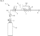
- a third embodiment of the invention is represented on [ Fig. 5 ], on which a residual pressure valve (RPV) 7 is added.
- the RPV 7 is placed upstream of the ESOV 4, but the RPV 7 may as well be placed downstream of the ESOV 4.
- the RPV 7 allows to keep a small amount of pressure stored to help the ESOV 4 engage more quickly.
- a gas filter 13 is also placed on the system, the gas filter 13 filtering out any unwanted particles.
- a fourth embodiment of the invention is represented on [ Fig. 6 ], on which a non-return valve (NRV) 8 is placed downstream of the ESOV 4.
- the NRV 8 allows the fluid to flow in only one direction and may be fitted to ensure that the fluid flows through the circuits in the right direction, where pressure conditions may otherwise cause reversed flow.
- the RPV 7 and the NRV 8 are placed upstream and downstream of the ESOV 4 respectively.
- the position of the RPV 7 and the NRV 8 might vary, i.e. their places might be interchanged, both the RPV 7 and the NRV 8 might be placed upstream of the ESOV 4 or downstream of the ESOV 4.
- the PRD 1 may have a NRV 8, and its position may vary. In addition, the number of non-return valves found in the PRD 1 may be more than one.
- a fifth embodiment of the invention is represented on [ Fig. 7 ], on which a closer look is taken on the emergency shutoff valve.
- the RPV 7 is used as the emergency shutoff valve.
- the RPV 7 will therefore have two roles, and will be used to close the system when the SRD 6 is open.
- a NRV 8 may also be placed downstream of the RPV 7.
- the RPV 7 can be used as an emergency shutoff valve, by connecting the SRD back to the RPV 7 through the relief fluid circuit 102.
- the NRV 8 shown on [ Fig. 7 ] is optional, may be placed somewhere else on the PRD 1 and may not be the only NRV on the system.
- a sixth embodiment of the invention is represented on [ Fig. 8 ], on which the RPV 7 acts as the ESOV 4, and where the RPV 7 comprises a NRV 8.
- This NRV feature might be added as a separate and complementary function.
- a seventh embodiment of the invention is represented on [ Fig. 9 ], on which we can see a close look at the relief fluid circuit 102.
- the SRD is the SRV 602
- the ESOV 4 is the RPV 7.
- a reset valve 9 is placed downstream of the SRV 602.
- the reset valve 9 is used to collect the overpressure at the back of the ESOV when the SRV 602, or more generally the SRD, is open.
- the reset valve is used to easily reopen the system by purging the zone downstream of the SRD and to the back of the ESOV (upstream).
- the emergency shutoff valve 4 and/or the residual pressure valve 7 may use gaskets and/or seals such as O-ring seals, said gaskets and/or seals being prone to leak. These leaks would be minimal but might need consideration. Therefore, the PRD 1 may comprise a bleeding valve 10, as shown on [ Fig. 9 ].
- the bleeding valve 10 allows minor amounts of fluid to be released from the system in case of, for example, leakage from elastomeric rings, to avoid any pressure build-up on the ESOV 4 or the RPV 7 that could hinder the system's core function, especially when the SRD 6 is not open.
- the bleeding valve 10 may also comprise a flap 1001, that would be pushed against the bleeding valve 10 in order to close it when the SRD 6 is open. This flap 1001 would deny the fluid to be released from the bleeding valve in case of pressure surge arising from the SRD 6.
- the flap 1001 may for example be made of polyurethane.
- Fig. 9 presents the SRV 602 as the SRD, but neither the reset valve nor the bleeding valve is limited to be used with a SRV only.
- the SRV 602 is there for the illustration purposes only and the invention is not limited to this type of SRD
- the residual pressure valve 7 comprises a middle chamber 701 in its central part, a front chamber 704, a back chamber 705 being respectively closer to the outlet interface 5 and to the bleeding valve 10, and also comprises a first piston 702.
- An entry connection 1102 connects the PRU 3 and the RPV 7
- a first connection 1103 connects the RPV 7 (downstream) and the SRD 6 (upstream)
- a second connection 1104 connects the SRD 6 (downstream) and the middle chamber 701 (upstream).
- the fluid in the front chamber 704 of the RPV 7 and in the first connection 1103 is smaller than the pressure P L , the fluid would not flow through the second connection 1104 as the SRD 6 is not open. In the contrary, if an overpressure is detected and the SRD 6 is open, the first piston 702 would prevent the fluid flow from going out of the outlet interface 5 as the released pressure would push the first piston 702 toward the outlet interface 5 until it is fully closed.
- the RPV 7 may also comprise a second piston 703, and the middle chamber 701 would be delimited by the first piston 702 and the second piston 703 on each side, and that in the open position of the safety relief device 6, the bleeding valve 10 is closed by the hinged flap 1001 as it is being pushed by the second piston 703 and is extending itself on the bleeding valve 10.
- the first piston 702 When the safety relief device 6 is open, the first piston 702 is pushed by the first springs 7021 as well as the pressure released to the middle chamber, said first piston 702 being pushed towards the outlet interface 5 in order to close the operational fluid circuit 101.
- the second piston 703 when the SRD is open, the second piston 703 is pulled away by the overpressure fluid released by the SRD to allow the flap 1001 to close the bleeding valve 10.
- a second springs 7031 could be used to reopen the bleeding valve 10.
Landscapes
- Engineering & Computer Science (AREA)
- Mechanical Engineering (AREA)
- General Engineering & Computer Science (AREA)
- Safety Valves (AREA)
- Control Of Fluid Pressure (AREA)
- Filling Or Discharging Of Gas Storage Vessels (AREA)
Abstract
Description
- The invention relates to the field of valves for compressed gas.
- More specifically, the invention relates to pressure reducing devices.
- Pressure reducing devices dedicated to high pressure fluids have been used for many years already. Pressure reducing devices allow to use high pressure sources, of for example 300 bar and higher, while remaining compatible with coupled installations that require a lower pressure inlet, of for example 200 bar and lower through the use of specifically made interfaces, i.e. valve delivery port specifically coded for such lower pressures as per applicable regulation/standard.
- A fluid's pressure and volume are correlated, as when the pressure increases, the volume decreases. Therefore, pressure reducing devices make the user's tasks easier as more gas can be stored in a higher-pressure vessel while keeping its volume small. Using a pressure reducing device will allow the user to have a desired pressure for the coupled installations that are typically designed for lower pressures, even if the stored fluid has a pressure being over the coupled installation's capacity. So, pressure reducing devices increase either usage autonomy at equivalent size of vessel, or increase portability, by reducing the vessel's size and weight.
- These pressure reducing devices are, for example, used in standalone cylinders, as well as bundles and trailers. This feature is concretely achieved by implementing an integrated pressure unit within the cylinder valve body (for instance, main shutoff valve, pressure regulating unit, emergency shutoff valve and safety relief device are integrated in same body), or with separate elements (main shutoff valve, pressure regulating unit, emergency shutoff valve and safety relief device are different objects) within a dedicated gas panel on the bundles, tube trailers,... The downstream end of the pressure reducing device may comprise an outlet valve, or it can be just a simple connection or interface.
- [
Fig. 1 ] represents a typical pressure reducing device as it is known in the art. The pressure reducing device comprises anoperational fluid circuit 101 having an optionalmain shutoff valve 2 allowing the opening-up of the pressure reducing unit, apressure regulating unit 3 reducing the pressure to a set desired value with a maximum pressure PA it can deliver, asafety relief device 6 opening itself in case of an excess pressure being higher than the maximum allowable pressure PA in the coupled downstream installation is present, and anoutlet interface 5 that may comprise a valve, being connected to the coupled installation. - The
Safety relief device 6 is located downstream of thepressure reducing unit 3 to protect the lower pressure side of the system. Thesafety relief device 6 can for example be a safety relief valve or a bursting disc, being respectively reversible and single use. Thesafety relief device 6 is designed to open in case of an unexpected excess pressure being higher than the maximum allowable pressure in the coupled installation is being detected, this excess pressure can for example be due to a failure or malfunction of thepressure reducing unit 3. Anoutlet interface 5 can be configured in different manners, such as threaded joint, quick-connect, featuring a check-valve, a non-return valve, a shut-off valve. Theoutlet interface 5 has a determined pressure PN (e.g. 200bar) which corresponds either to its pressure capability or rating. The fluid passing through the safety relief device is vented either directly to atmosphere or might be collected. - On [
fig. 1 ], an optional gas filter can be placed between themain shutoff valve 2 and thepressure reducing unit 3, but it is possible to be placed upstream of the main shutoff valve, and an optional non-return valve can be placed in the fluid circuit, downstream the emergency shutoff valve. There can be several filters. - Having the fluid vented away from the system or stored as it is currently done presents some issues and can't be accepted under certain circumstances. For instance, the fluid contained might be a flammable medium such as hydrogen or other fluids creating dangerous and/or toxic environments, e.g. ATEX (Atmosphere Explosives).
- Indeed, in case of a flammable medium such as hydrogen, a free venting in the atmosphere might lead to generation of an explosive zone if the area is confined or insufficiently vented; this requires an expansive setup by the user, such as gas detection with automatic shutoff, or alternatively a strong ventilation if the mobile is used indoor.
- Although the safety relief device can be collected to a complimentary exhaust pipeline or equivalent, it would complicate the connection process to the installation by requiring additional setups and extra handling steps, for example extensive safety checks, relying on a procedural barrier.
- Moreover, safety relief devices are mechanical components and are therefore prone to failure. Although these devices are designed to be highly reliable, malfunctions and defects should always be taken into consideration.
- Solutions to the above-mentioned issues do exist, such as implementing an automatic valve, e.g. pneumatic, upstream or downstream of the pressure reducing unit as well as a pressure sensor and/or switch downstream. In the case of implementing external logics such as a PLC (programmable logic controller), any sensed pressure increase would lead to a closing of the automatic valve. This type of technology would require extra external energy, for example compressed dry air (CDA) for valve actuation or electricity to manage a PLC and a solenoid. This solution would not be satisfactory in many situations, and the quality-price ratio is low.
- Another solution to the above-mentioned issues would be to make the coupled installation self-protected by installing a compliant safety relief device at the inlet of installation, which would still need connection to a relevant exhaust line. This solution would be implemented at excessive costs.
- As it has been discussed, there is a need for a safe, simple, and easy to use pressure reducing device to avoid any endangerment of people and work environment.
- To this end, the invention relates to a pressure reducing device comprising an upstream end configured to be connected to a pressurized gas source and a downstream end configured to be connected to a coupled installation and comprising:
- an operational fluid circuit comprising a pressure reducing unit configured to reduce the pressure of a pressurized gas flow to a maximum pressure PA, an emergency shut-off valve and an outlet interface with a pressure capability PN,
- a relief fluid circuit comprising a first end connected to the operational fluid circuit downstream of the pressure reducing unit and a safety relief device,
- a closed state where the safety relief device is inactive and the emergency shutoff valve is open, when the pressure in the pressure reducing valve is lower than a predetermined pressure PL, and
- an open state where the safety relief device is active and the emergency shutoff valve is closed, when the pressure in the fluid circuit downstream of the pressure reducing unit is higher to the predetermined pressure PL,
- So, the invention solves the above-mentioned problems by implementing a failure safe feature on the pressure reducing device (PRD) that prevents any release of fluid to the atmosphere while requiring no external energy and no extra components such as a PLC system. In case of failure, the pressure increases in the PRD will lead to a spontaneous shutoff of the feeding flow, fully protecting the downstream coupled installation by shutting down the pressure source.
- The emergency shutoff valve will get actuated by the overpressure released through the safety relief device (SRD) in case of failure of the pressure reducing unit (PRU). So, instead of releasing the overpressure fluid to atmosphere, the invention allows to advantageously and safely shut down the gas stream.
- A first variant would be that the operational fluid circuit of the pressure reducing device may comprise a residual pressure valve. Having a residual pressure valve (RPV) may help the emergency shutoff valve (ESOV) engage more quickly when the SRD is open by keeping a small amount of pressure stored in the RPV.
- A second variant of the invention would be that the residual pressure valve may comprise the emergency shutoff valve. Using the residual pressure valve as the emergency shutoff valve would save space as well as reduce the complexity of the fluid circuits used.
- A third variant of the invention would be that the pressure reducing valve may also comprise a non-return valve. A non-return valve (NRV) will allow the fluid to flow through it in only one direction. It also always maintains a positive pressure in the system, while preventing any unwanted material from inadvertently being backed into the previous components of the PRD. The non-return function would allow to balance pressures in case of backflow from downstream as well as keeping the emergency shutoff valve closed by stopping the backflow to come back to the ESOV.
- A fourth variant of the invention would be that a non-return valve may be comprised in the emergency shutoff valve. Having a NRV in the ESOV would also save space on the operational fluid circuit.
- A first option of the invention would be that the safety relief device comprises a bursting disc. A bursting disc (BD) is a sacrificial part as it has a one-time-use membrane that fails at a predetermined pressure. If the BD is opened, or more precisely burst, a simple replacement can be executed and maintenance on PRD becomes simple.
- A second option of the invention would be that the safety relief device comprises a safety relief valve. A safety relief valve (SRV) will reduce costs as well as remove the need to have access to extra parts (compared to the use of a BD). The safety relief valve is reversible, and the system could easily be reset.
- A fifth variant of the invention would be that the safety relief device and the emergency shutoff valve may be connected through a fluid connection, said connection comprising a reset valve. A reset valve will allow to release the pressure when the SRD has been opened and that the ESOV is closed. The reset valve allows a quick and easy reset of the PRD by purging the relief fluid circuit downstream of the SRV.
- The pressure reducing device may be a one-way valve. Such a PRD is used for fluid delivery only, and is for example a bundle.
- The pressure reducing device may also be a two-way valve. In that case, the PRD would allow both delivery and filling through either an external neutralization process for single ported valves or through implementation of a dedicated filling port, for example for standalone cylinders or bundles featuring a single valve.
- A sixth variant of the invention would be that the pressure reducing device may comprise a bleeding valve. A bleeding valve allows minute amounts of fluid to be released in case of leak, for example from elastomeric ring seals, to avoid any pressure build up on the ESOV, which could otherwise hinder the ESOV's expected function. The bleeding valve could be comprised in the relief fluid circuit.
- A seventh variant of the invention would be that the relief fluid circuit comprises a flap may be leaning against the bleeding valve. When the ESOV is closed, the flap will automatically close as well to avoid any release of fluid to the atmosphere.
- In a preferred embodiment of the invention, a central part of the residual pressure valve comprises a first piston being mobile in a middle chamber, and the residual pressure valve has three connections:
- An entry connection fluidly connecting the pressure reducing unit outlet to the residual pressure valve,
- a first connection fluidly connecting the residual pressure valve outlet to the safety relief device and
- a second connection fluidly connecting the safety relief device to the middle chamber of the residual pressure valve,
- In this embodiment, a middle chamber is made in the central part of the RPV for the fluid returning from the SRD to the RPV, in case the SRD is opened. When the SRD is opened, the first piston is pushed towards the outlet valve, being the coupled installation's inlet, to close the system.
- The central part of the residual pressure valve may also comprise a second piston, the middle chamber being delimited by the first piston and the second piston, and in the open position of the safety relief device, the bleeding valve is closed by the second piston. The second piston would put the bleeding valve's flap in place or be pushed towards the bleeding valve in order to deny any pressure evacuation from the bleeding valve when the SRD is open.
- The invention also related to a device for storing and supplying compressed gas comprising a fluid source and a pressure reducing device comprising any of preceding characteristics.
- The invention is further elucidated in the appending figures and figure description explaining preferred embodiments of the invention. Note that the figures are not drawn to scale. The figures are intended to describe the principles of the invention.
- [
Fig. 1 ] is a functional representation of the state of the art. - [
Fig. 2 ] is a functional representation of the core of the invention. - [
Fig. 3 ] is a zoomed in functional representation of the relief fluid circuit of a first embodiment of the invention, comprising a bursting disc as the safety relief device. - [
Fig. 4 ] is a zoomed in functional representation of the relief fluid circuit of a second embodiment of the invention, comprising a safety relief valve as the safety relief device. - [
Fig. 5 ] is a functional representation of a third embodiment of the invention, comprising a residual pressure valve. - [
Fig. 6 ] is a functional representation of a fourth embodiment of the invention, comprising a residual pressure valve and a non-return valve. - [
Fig. 7 ] is a zoomed in functional representation of a fifth embodiment of the invention, comprising a non-return valve, and where the emergency shutoff valve is a residual pressure valve. - [
Fig. 8 ] is a zoomed in functional representation of a sixth embodiment of the invention, where the emergency shutoff valve is a residual pressure valve, and where the non-return valve is comprised in the residual pressure valve. - [
Fig. 9 ] is a zoomed in functional representation of a seventh embodiment of the invention, where the safety relief device is a safety relief valve, where the residual pressure valve acts as the emergency shutoff valve, the invention comprising a reset valve and a bleeding valve. - [
Fig. 10 ] represents a sketch of an eighth embodiment of the invention, in particular its residual pressure valve. - Unless stated otherwise, a same element appearing on different figures presents a single reference.
- Furthermore, the terms "first", "second", and the like in the description and in the claims, are used for distinguishing between similar elements and not necessarily for describing a sequential or chronological order.
- A fluid flows from a starting point of a fluid circuit to an end point of a circuit, passing through parts of the fluid circuits, e.g., valves. Positions may be referred to as downstream or upstream of a certain part. "Upstream" is used to describe a position on the circuit, in or before the said part with respect to the direction of the fluid flow whereas "downstream" is used to describe a position on the circuit in or after the said part with respect to the direction of the fluid flow.
- [
Fig. 1 ] has already been described regarding the state of the art. - [
Fig. 2 ] represents the core of the invention. Afluid source 12 feeds the pressure reducing device (PRD) 1, this fluid source being for example a vessel. ThePRD 1 comprises anoperational fluid circuit 101 and arelief fluid circuit 102. The PRD inlet can be opened by a main shutoff valve (MSOV) 2, theMSOV 2 being part of theoperational fluid circuit 101. A pressure reducing unit (PRU) 3 is also situated on theoperational fluid circuit 101, and is used as a control valve that reduces higher upstream pressure to predetermined lower constant downstream pressure. ThePRU 3 can for example be operated by a spring set to allow a certain pressure to flow through it, the spring being preferably a "Belleville spring". Themain shutoff valve 2 and thepressure regulating unit 3 can be provided by single valve. - A Safety relief device (SRD) 6 is also connected to the system to detect any overpressure in the
PRD 1. Such an overpressure downstream of thePRU 3 can for example be caused by amalfunctioning PRU 3, a failure of thePRU 3 or a setting error. TheSRD 6 will open itself when an overpressure is detected (when subjected to an overpressure) and therefore, the fluid would pass through theopen SRD 6. Therelief fluid circuit 102 prevents any release of fluid outside of thePRD 1 as it is connected to an emergency shutoff valve (ESOV) 4. TheESOV 4 is used and configured to close the system when theSRD 6 is opened, by receiving the overpressure from therelief fluid circuit 102. - An
outlet interface 5 may be placed downstream of thePRD 1 and is used to let the fluid go out of thePRD 1 and to go to a coupled installation. Agas filter 13 may also be added to thePRD 1, preferentially upstream of thePRU 3. Such a gas filter may be used to filter out any unwanted particles in the system, such as dirt or rust particles. - All or some of the
operational fluid circuit 101,relief fluid circuit 102, main shutoff valve (MSOV) 2, emergency shutoff valve (ESOV) 4 andoutlet interface 5 may be integrated into a common body configured to be removably connected to a fluid source 2 (or separate bodies fluidly connected together). - An overpressure is defined as a pressure being higher than the limit allowable pressure PL of the coupled installation, PL being between PA + 5% and PA+ 500% and/or between PN + 5% and PN +500%, preferably +20%, PA and PN are generally comprised between 200 bar and 300 bar, depending on the coupled installation capabilities. That is to say, when the pressure downstream the
pressure reducing unit 3 is abnormal (above the pressure capability PN of theoutlet interface 5 and/or exceeds the maximum pressure PA of thepressure reducing unit 3 to a predetermined value such as +5% to 500% and preferably +20%) thesafety relief device 6 is automatically opened, and theemergency shutoff valve 4 closed. - The
SRD 6 can, for example, be a bursting disc 601 (BD), a safety relief valve 602 (SRV), balanced bellows, or power actuated, but theSRD 6 is preferentially a BD or a SRV. - A first embodiment is represented on [
Fig. 3 ], on which it shows a closer look at theSRD 6. In this first embodiment, theSRD 6 is a bursting disc (BD) 601. TheBD 601 is a sacrificial part because it has a one-time-use membrane that fails at a predetermined pressure. If theBD 601 is burst, a simple replacement can be executed and maintenance on thePRD 1 becomes simple. In case of overpressure, theBD 601 bursts, letting the fluid flow in therelief fluid circuit 102 to theESOV 4, saidESOV 4 closing theoperational fluid circuit 101, and consequently thewhole PRD 1, to avoid any overpressure going to the coupled installation. - A second embodiment is represented on [
Fig. 4 ], on which it shows a closer look at theSRD 6. In this second embodiment, theSRD 6 is a safety relief valve (SRV) 602. TheSRV 602 is reversible, and the system could easily be reset. In case of overpressure, theSRV 602 opens, letting the overpressure fluid go through therelief fluid circuit 102 to theESOV 4, saidESOV 4 closing theoperational fluid circuit 101 to avoid any overpressure going to the coupled installation. - A third embodiment of the invention is represented on [
Fig. 5 ], on which a residual pressure valve (RPV) 7 is added. In this example, theRPV 7 is placed upstream of theESOV 4, but theRPV 7 may as well be placed downstream of theESOV 4. TheRPV 7 allows to keep a small amount of pressure stored to help theESOV 4 engage more quickly. Agas filter 13 is also placed on the system, thegas filter 13 filtering out any unwanted particles. - A fourth embodiment of the invention is represented on [
Fig. 6 ], on which a non-return valve (NRV) 8 is placed downstream of theESOV 4. TheNRV 8 allows the fluid to flow in only one direction and may be fitted to ensure that the fluid flows through the circuits in the right direction, where pressure conditions may otherwise cause reversed flow. - On [
Fig. 6 ], theRPV 7 and theNRV 8 are placed upstream and downstream of theESOV 4 respectively. However, the position of theRPV 7 and theNRV 8 might vary, i.e. their places might be interchanged, both theRPV 7 and theNRV 8 might be placed upstream of theESOV 4 or downstream of theESOV 4. - The
PRD 1 may have aNRV 8, and its position may vary. In addition, the number of non-return valves found in thePRD 1 may be more than one. - A fifth embodiment of the invention is represented on [
Fig. 7 ], on which a closer look is taken on the emergency shutoff valve. In this case, theRPV 7 is used as the emergency shutoff valve. TheRPV 7 will therefore have two roles, and will be used to close the system when theSRD 6 is open. ANRV 8 may also be placed downstream of theRPV 7. - The
RPV 7 can be used as an emergency shutoff valve, by connecting the SRD back to theRPV 7 through therelief fluid circuit 102. As stated earlier, theNRV 8 shown on [Fig. 7 ] is optional, may be placed somewhere else on thePRD 1 and may not be the only NRV on the system. - A sixth embodiment of the invention is represented on [
Fig. 8 ], on which theRPV 7 acts as theESOV 4, and where theRPV 7 comprises aNRV 8. This NRV feature might be added as a separate and complementary function. - A seventh embodiment of the invention is represented on [
Fig. 9 ], on which we can see a close look at therelief fluid circuit 102. In this seventh embodiment, the SRD is theSRV 602, and theESOV 4 is theRPV 7. - A reset valve 9 is placed downstream of the
SRV 602. The reset valve 9 is used to collect the overpressure at the back of the ESOV when theSRV 602, or more generally the SRD, is open. The reset valve is used to easily reopen the system by purging the zone downstream of the SRD and to the back of the ESOV (upstream). - The
emergency shutoff valve 4 and/or theresidual pressure valve 7 may use gaskets and/or seals such as O-ring seals, said gaskets and/or seals being prone to leak. These leaks would be minimal but might need consideration. Therefore, thePRD 1 may comprise a bleedingvalve 10, as shown on [Fig. 9 ]. The bleedingvalve 10 allows minor amounts of fluid to be released from the system in case of, for example, leakage from elastomeric rings, to avoid any pressure build-up on theESOV 4 or theRPV 7 that could hinder the system's core function, especially when theSRD 6 is not open. In addition, the bleedingvalve 10 may also comprise aflap 1001, that would be pushed against the bleedingvalve 10 in order to close it when theSRD 6 is open. Thisflap 1001 would deny the fluid to be released from the bleeding valve in case of pressure surge arising from theSRD 6. Theflap 1001 may for example be made of polyurethane. - [
Fig. 9 ] presents theSRV 602 as the SRD, but neither the reset valve nor the bleeding valve is limited to be used with a SRV only. TheSRV 602 is there for the illustration purposes only and the invention is not limited to this type of SRD - [
Fig. 10 ] presents an eighth embodiment, focusing the view on theRPV 7. Theresidual pressure valve 7 comprises amiddle chamber 701 in its central part, afront chamber 704, aback chamber 705 being respectively closer to theoutlet interface 5 and to the bleedingvalve 10, and also comprises afirst piston 702. Anentry connection 1102 connects thePRU 3 and theRPV 7, afirst connection 1103 connects the RPV 7 (downstream) and the SRD 6 (upstream), and asecond connection 1104 connects the SRD 6 (downstream) and the middle chamber 701 (upstream). If the pressure in thefront chamber 704 of theRPV 7 and in thefirst connection 1103 is smaller than the pressure PL, the fluid would not flow through thesecond connection 1104 as theSRD 6 is not open. In the contrary, if an overpressure is detected and theSRD 6 is open, thefirst piston 702 would prevent the fluid flow from going out of theoutlet interface 5 as the released pressure would push thefirst piston 702 toward theoutlet interface 5 until it is fully closed. - The
RPV 7 may also comprise asecond piston 703, and themiddle chamber 701 would be delimited by thefirst piston 702 and thesecond piston 703 on each side, and that in the open position of thesafety relief device 6, the bleedingvalve 10 is closed by the hingedflap 1001 as it is being pushed by thesecond piston 703 and is extending itself on the bleedingvalve 10. - When the
safety relief device 6 is open, thefirst piston 702 is pushed by thefirst springs 7021 as well as the pressure released to the middle chamber, saidfirst piston 702 being pushed towards theoutlet interface 5 in order to close theoperational fluid circuit 101. Similarly, when the SRD is open, thesecond piston 703 is pulled away by the overpressure fluid released by the SRD to allow theflap 1001 to close the bleedingvalve 10. Asecond springs 7031 could be used to reopen the bleedingvalve 10. - While the invention has been described in conjunction with specific embodiments thereof, it is important to note that combinations of embodiments is feasible and may be considered.
Claims (17)
- A pressure reducing device (1) comprising an upstream end configured to be connected to a pressurized gas source and a downstream end configured to be connected to a coupled installation and comprising:- an operational fluid circuit (101) comprising a pressure reducing unit (3) configured to reduce the pressure of a pressurized gas flow to a maximum pressure PA, an emergency shut-off valve (4, 7) and an outlet interface (5) with a pressure capability PN,- a relief fluid circuit (102) comprising a first end connected to the operational fluid circuit (101) downstream of the pressure reducing unit (3) and a safety relief device (6)characterized in that the relief fluid circuit (102) comprises a second end connected to the emergency shutoff valve (4), and that the safety relief device (6) is configured to have at least two states,- a closed state where the safety relief device (6) is inactive and the emergency shutoff valve (4, 7) is open, when the pressure in the fluid circuit (101) downstream of the pressure reducing unit (3) is lower than a predetermined pressure PL, and- an open state where the safety relief device (6) is active and the emergency shutoff valve (4, 7) is closed, when the pressure in the fluid circuit (101) downstream of the pressure reducing unit (3) is higher to the predetermined pressure PL,the predetermined pressure PL being between PA + 5% and PA+ 500% and/or between PN + 5% and PN +500%, preferably +20%.
- A pressure reducing device (1) according to claim 1, characterized in that operational fluid circuit (101) comprises a main shutoff valve (2).
- A pressure reducing device (1) according to claim 1, characterized in that the operational fluid circuit (101) comprises a residual pressure valve (7).
- A pressure reducing device (1) according to the preceding claims, characterized in that the residual pressure valve (7) is the emergency shutoff valve (4).
- A pressure reducing device (1) according to any of the preceding claims, characterized in that it comprises a non-return valve (8).
- A pressure reducing device (1) according to the preceding claim characterized in that the non-return valve (8) is comprised in the emergency shutoff valve (4, 7).
- A pressure reducing device (1) according to any of the preceding claims, characterized in that the safety relief device (6) comprises a bursting disc (601).
- A pressure reducing device (1) according to any of the preceding claims, characterized in that the safety relief device (6) comprises a safety relief valve (602).
- A pressure reducing device (1) according to any of the preceding claims, characterized in that the safety relief device (6) and the emergency shutoff valve (4, 7) are connected through a fluid connection, said fluid connection comprising a reset valve (9).
- A pressure reducing device (1) according to any of the preceding claims, characterized in that it is a one-way valve.
- A pressure reducing device (1) according to claims 1 to 8, characterized in that it is a two-way valve.
- A pressure reducing device (1) according to any of the preceding claims, characterized in that it comprises a bleeding valve (10).
- A pressure reducing device (1) according to claim 11, characterized in that the relief fluid circuit (102) comprises the bleeding valve (10).
- A pressure reducing device (1) according to any of the claims 11 and 12, characterized in that the relief fluid circuit (102) comprises a flap (1001) leaning against the bleeding valve (10).
- A pressure reducing device (1) according to any of the preceding claims to the extent that it depends on claim 3, characterized in that a central part of the residual pressure valve (7) comprises a first piston (702) being mobile in a middle chamber (701), and in that the residual pressure (7) valve has three connections:- an entry connection (1102) fluidly connecting the pressure reducing unit (3) outlet to the residual pressure valve (7),- a first connection (1103) fluidly connecting the residual pressure valve (7) outlet to the safety relief device (6) and- a second connection (1104) fluidly connecting the safety relief device (6) outlet to the middle chamber (701) of the residual pressure valve (7),and that in the open position of the safety relief device (6), the outlet interface (5) is moved in a closed state by the first piston (702).
- A pressure reducing device (1) according to claims 11 and 14 characterized in that the central part of the residual pressure valve (7) comprises a second piston (703), and in that the middle chamber (701) is delimited by the first piston (702) and the second piston (703), and that in the open position of the safety relief device (6), the bleeding valve (10) is moved in a closed position by the second piston (703).
- Device for storing and supplying compressed gas comprising a fluid source (12) and a pressure reducing device (1) according to any of preceding claims.
Priority Applications (10)
| Application Number | Priority Date | Filing Date | Title |
|---|---|---|---|
| EP21179536.4A EP4105542B1 (en) | 2021-06-15 | 2021-06-15 | Pressure reducing device |
| BR112023026047A BR112023026047A2 (en) | 2021-06-15 | 2022-06-08 | PRESSURE REDUCING DEVICE |
| US18/570,196 US20240288127A1 (en) | 2021-06-15 | 2022-06-08 | Pressure reducing device |
| KR1020247000626A KR20240020276A (en) | 2021-06-15 | 2022-06-08 | pressure relief device |
| PCT/EP2022/065496 WO2022263247A1 (en) | 2021-06-15 | 2022-06-08 | Pressure reducing device |
| MX2023014909A MX2023014909A (en) | 2021-06-15 | 2022-06-08 | Pressure reducing device. |
| AU2022293931A AU2022293931A1 (en) | 2021-06-15 | 2022-06-08 | Pressure reducing device |
| CN202280041153.3A CN117460911A (en) | 2021-06-15 | 2022-06-08 | pressure reducing device |
| JP2023575700A JP2024525314A (en) | 2021-06-15 | 2022-06-08 | Pressure reducing device |
| CA3220995A CA3220995A1 (en) | 2021-06-15 | 2022-06-08 | Pressure reducing device |
Applications Claiming Priority (1)
| Application Number | Priority Date | Filing Date | Title |
|---|---|---|---|
| EP21179536.4A EP4105542B1 (en) | 2021-06-15 | 2021-06-15 | Pressure reducing device |
Publications (2)
| Publication Number | Publication Date |
|---|---|
| EP4105542A1 true EP4105542A1 (en) | 2022-12-21 |
| EP4105542B1 EP4105542B1 (en) | 2026-05-06 |
Family
ID=76764810
Family Applications (1)
| Application Number | Title | Priority Date | Filing Date |
|---|---|---|---|
| EP21179536.4A Active EP4105542B1 (en) | 2021-06-15 | 2021-06-15 | Pressure reducing device |
Country Status (10)
| Country | Link |
|---|---|
| US (1) | US20240288127A1 (en) |
| EP (1) | EP4105542B1 (en) |
| JP (1) | JP2024525314A (en) |
| KR (1) | KR20240020276A (en) |
| CN (1) | CN117460911A (en) |
| AU (1) | AU2022293931A1 (en) |
| BR (1) | BR112023026047A2 (en) |
| CA (1) | CA3220995A1 (en) |
| MX (1) | MX2023014909A (en) |
| WO (1) | WO2022263247A1 (en) |
Citations (7)
| Publication number | Priority date | Publication date | Assignee | Title |
|---|---|---|---|---|
| US4188971A (en) * | 1978-04-27 | 1980-02-19 | The United States Of America As Represented By The Secretary Of The Navy | Fluid cutout valve |
| GB2287330A (en) * | 1994-03-08 | 1995-09-13 | Trevor Thomas Jenkins | Pressure-activated safety shut-off valve |
| EP0532402B1 (en) * | 1991-09-13 | 1996-01-10 | Gaz De France (Service National) | Automatic stop- and safety device, especially for gas expansion stations |
| US5752544A (en) * | 1995-12-01 | 1998-05-19 | Gaz De France | Device for feeding a distribution network with gaseous fluid |
| US20140318642A1 (en) * | 2013-04-25 | 2014-10-30 | Spectron Gas Control Systems GmbH | Safety device for installation in a gas-supply system, in particular, an acetylene-supply system |
| US9328745B2 (en) * | 2012-11-05 | 2016-05-03 | Magna Steyr Fahrzeugtechnik Ag & Co Kg | Pressure storage system and method to operate pressure storage system |
| EP3495713A1 (en) * | 2017-12-06 | 2019-06-12 | Micro Matic A/S | A valve assembly |
Family Cites Families (3)
| Publication number | Priority date | Publication date | Assignee | Title |
|---|---|---|---|---|
| US4471812A (en) * | 1982-03-01 | 1984-09-18 | Paul Bertsch | Remote relief-vent device |
| JP2602880B2 (en) * | 1988-03-05 | 1997-04-23 | 忠弘 大見 | Cylinder cabinet plumbing equipment |
| FR2926871B1 (en) * | 2008-01-30 | 2010-04-02 | Air Liquide | DEVICE FOR FILLING AND DISPENSING GAS AND ASSEMBLY COMPRISING SUCH A DEVICE |
-
2021
- 2021-06-15 EP EP21179536.4A patent/EP4105542B1/en active Active
-
2022
- 2022-06-08 MX MX2023014909A patent/MX2023014909A/en unknown
- 2022-06-08 BR BR112023026047A patent/BR112023026047A2/en not_active Application Discontinuation
- 2022-06-08 AU AU2022293931A patent/AU2022293931A1/en active Pending
- 2022-06-08 WO PCT/EP2022/065496 patent/WO2022263247A1/en not_active Ceased
- 2022-06-08 CA CA3220995A patent/CA3220995A1/en active Pending
- 2022-06-08 KR KR1020247000626A patent/KR20240020276A/en active Pending
- 2022-06-08 JP JP2023575700A patent/JP2024525314A/en active Pending
- 2022-06-08 US US18/570,196 patent/US20240288127A1/en active Pending
- 2022-06-08 CN CN202280041153.3A patent/CN117460911A/en active Pending
Patent Citations (7)
| Publication number | Priority date | Publication date | Assignee | Title |
|---|---|---|---|---|
| US4188971A (en) * | 1978-04-27 | 1980-02-19 | The United States Of America As Represented By The Secretary Of The Navy | Fluid cutout valve |
| EP0532402B1 (en) * | 1991-09-13 | 1996-01-10 | Gaz De France (Service National) | Automatic stop- and safety device, especially for gas expansion stations |
| GB2287330A (en) * | 1994-03-08 | 1995-09-13 | Trevor Thomas Jenkins | Pressure-activated safety shut-off valve |
| US5752544A (en) * | 1995-12-01 | 1998-05-19 | Gaz De France | Device for feeding a distribution network with gaseous fluid |
| US9328745B2 (en) * | 2012-11-05 | 2016-05-03 | Magna Steyr Fahrzeugtechnik Ag & Co Kg | Pressure storage system and method to operate pressure storage system |
| US20140318642A1 (en) * | 2013-04-25 | 2014-10-30 | Spectron Gas Control Systems GmbH | Safety device for installation in a gas-supply system, in particular, an acetylene-supply system |
| EP3495713A1 (en) * | 2017-12-06 | 2019-06-12 | Micro Matic A/S | A valve assembly |
Also Published As
| Publication number | Publication date |
|---|---|
| MX2023014909A (en) | 2024-02-28 |
| WO2022263247A1 (en) | 2022-12-22 |
| EP4105542B1 (en) | 2026-05-06 |
| US20240288127A1 (en) | 2024-08-29 |
| BR112023026047A2 (en) | 2024-03-05 |
| CA3220995A1 (en) | 2022-12-22 |
| AU2022293931A1 (en) | 2024-01-25 |
| JP2024525314A (en) | 2024-07-12 |
| KR20240020276A (en) | 2024-02-14 |
| CN117460911A (en) | 2024-01-26 |
Similar Documents
| Publication | Publication Date | Title |
|---|---|---|
| EP2347158B1 (en) | Valves having removable internal actuation mechanisms | |
| CN103863096B (en) | Pressure storage system and method for operating the same | |
| US20100319804A1 (en) | Device for filling and distributing gas and assembly comprising such a device | |
| EP3112690A1 (en) | Pneumatically actuated hpc bleed valve, which is controlled by a solenoid valve, which in turn is assisted in its closing position by a flow limiting valve | |
| KR101403189B1 (en) | Pressurised fluid cylinders | |
| WO2011002552A1 (en) | Methods and apparatus to charge accumulator apparatus | |
| AU2010337322A1 (en) | Apparatus to increase a force of an actuator having an override apparatus | |
| EP0050926B1 (en) | Improved expansible tube type valve | |
| EP4105542B1 (en) | Pressure reducing device | |
| CN112823255A (en) | Emergency shutdown safety assembly for providing redundant safety shutdown | |
| CA2035682C (en) | Safety device and method | |
| CN110725978A (en) | Quick automatic shut-off device and natural gas wellhead emergency cut-off device | |
| US3709241A (en) | Fill limiter, check and safety valve | |
| RU16024U1 (en) | EMERGENCY CLOSING AUTOMATIC GAS PIPELINE | |
| US20230376053A1 (en) | Blocking device for pipelines for the passage of pressurized gas, of the pilot-operated type, and pressure regulator for said blocking device | |
| EP2564099B1 (en) | Controlling fluid flow | |
| CN114321462A (en) | Differential pressure control cut-off and relief device and differential pressure control cut-off system | |
| US8251089B1 (en) | Relief system for process fluids under pressure | |
| WO2006108770A2 (en) | Pressure regulating device for natural gas | |
| CN222047418U (en) | A safety device for reducing pressure and preventing backflow | |
| CN221145425U (en) | High-pressure bottle valve with flow limiting mechanism | |
| CN114962724B (en) | General pressure switch of integrated relief valve and gas equipment | |
| CN212155848U (en) | Pneumatic angle seat valve with adjusting hand wheel | |
| WO2025054737A1 (en) | Apparatus and method for pressure protection in a gaseous fuel system | |
| CN118856062A (en) | A threaded cartridge high pressure safety valve |
Legal Events
| Date | Code | Title | Description |
|---|---|---|---|
| PUAI | Public reference made under article 153(3) epc to a published international application that has entered the european phase |
Free format text: ORIGINAL CODE: 0009012 |
|
| STAA | Information on the status of an ep patent application or granted ep patent |
Free format text: STATUS: THE APPLICATION HAS BEEN PUBLISHED |
|
| AK | Designated contracting states |
Kind code of ref document: A1 Designated state(s): AL AT BE BG CH CY CZ DE DK EE ES FI FR GB GR HR HU IE IS IT LI LT LU LV MC MK MT NL NO PL PT RO RS SE SI SK SM TR |
|
| STAA | Information on the status of an ep patent application or granted ep patent |
Free format text: STATUS: REQUEST FOR EXAMINATION WAS MADE |
|
| 17P | Request for examination filed |
Effective date: 20230621 |
|
| RBV | Designated contracting states (corrected) |
Designated state(s): AL AT BE BG CH CY CZ DE DK EE ES FI FR GB GR HR HU IE IS IT LI LT LU LV MC MK MT NL NO PL PT RO RS SE SI SK SM TR |
|
| STAA | Information on the status of an ep patent application or granted ep patent |
Free format text: STATUS: EXAMINATION IS IN PROGRESS |
|
| 17Q | First examination report despatched |
Effective date: 20240925 |
|
| RAP3 | Party data changed (applicant data changed or rights of an application transferred) |
Owner name: L'AIR LIQUIDE, SOCIETE ANONYME POUR L'ETUDEET L'EXPLOITATION DES PROCEDES GEORGES CLAUDE Owner name: AIR LIQUIDE DEUTSCHLAND GMBH |
|
| GRAP | Despatch of communication of intention to grant a patent |
Free format text: ORIGINAL CODE: EPIDOSNIGR1 |
|
| STAA | Information on the status of an ep patent application or granted ep patent |
Free format text: STATUS: GRANT OF PATENT IS INTENDED |
|
| INTG | Intention to grant announced |
Effective date: 20260210 |
|
| GRAS | Grant fee paid |
Free format text: ORIGINAL CODE: EPIDOSNIGR3 |
|
| GRAA | (expected) grant |
Free format text: ORIGINAL CODE: 0009210 |
|
| STAA | Information on the status of an ep patent application or granted ep patent |
Free format text: STATUS: THE PATENT HAS BEEN GRANTED |
|
| RIN1 | Information on inventor provided before grant (corrected) |
Inventor name: MULLER, DENIS Inventor name: KREMER, ROBERT Inventor name: IBALD, DANIEL |
|
| AK | Designated contracting states |
Kind code of ref document: B1 Designated state(s): AL AT BE BG CH CY CZ DE DK EE ES FI FR GB GR HR HU IE IS IT LI LT LU LV MC MK MT NL NO PL PT RO RS SE SI SK SM TR |
|
| REG | Reference to a national code |
Ref country code: CH Ref legal event code: F10 Free format text: ST27 STATUS EVENT CODE: U-0-0-F10-F00 (AS PROVIDED BY THE NATIONAL OFFICE) Effective date: 20260506 Ref country code: GB Ref legal event code: FG4D |