EP4105524A1 - Dichtring einer gleitringdichtung sowie gleitringdichtung mit einem solchen dichtring - Google Patents
Dichtring einer gleitringdichtung sowie gleitringdichtung mit einem solchen dichtring Download PDFInfo
- Publication number
- EP4105524A1 EP4105524A1 EP22179160.1A EP22179160A EP4105524A1 EP 4105524 A1 EP4105524 A1 EP 4105524A1 EP 22179160 A EP22179160 A EP 22179160A EP 4105524 A1 EP4105524 A1 EP 4105524A1
- Authority
- EP
- European Patent Office
- Prior art keywords
- sealing ring
- channel
- outflow channel
- sealing
- inflow
- Prior art date
- Legal status (The legal status is an assumption and is not a legal conclusion. Google has not performed a legal analysis and makes no representation as to the accuracy of the status listed.)
- Granted
Links
Images


Classifications
-
- F—MECHANICAL ENGINEERING; LIGHTING; HEATING; WEAPONS; BLASTING
- F16—ENGINEERING ELEMENTS AND UNITS; GENERAL MEASURES FOR PRODUCING AND MAINTAINING EFFECTIVE FUNCTIONING OF MACHINES OR INSTALLATIONS; THERMAL INSULATION IN GENERAL
- F16J—PISTONS; CYLINDERS; SEALINGS
- F16J15/00—Sealings
- F16J15/16—Sealings between relatively-moving surfaces
- F16J15/34—Sealings between relatively-moving surfaces with slip-ring pressed against a more or less radial face on one member
-
- F—MECHANICAL ENGINEERING; LIGHTING; HEATING; WEAPONS; BLASTING
- F16—ENGINEERING ELEMENTS AND UNITS; GENERAL MEASURES FOR PRODUCING AND MAINTAINING EFFECTIVE FUNCTIONING OF MACHINES OR INSTALLATIONS; THERMAL INSULATION IN GENERAL
- F16J—PISTONS; CYLINDERS; SEALINGS
- F16J15/00—Sealings
- F16J15/16—Sealings between relatively-moving surfaces
- F16J15/34—Sealings between relatively-moving surfaces with slip-ring pressed against a more or less radial face on one member
- F16J15/3404—Sealings between relatively-moving surfaces with slip-ring pressed against a more or less radial face on one member and characterised by parts or details relating to lubrication, cooling or venting of the seal
- F16J15/3408—Sealings between relatively-moving surfaces with slip-ring pressed against a more or less radial face on one member and characterised by parts or details relating to lubrication, cooling or venting of the seal at least one ring having an uneven slipping surface
- F16J15/3412—Sealings between relatively-moving surfaces with slip-ring pressed against a more or less radial face on one member and characterised by parts or details relating to lubrication, cooling or venting of the seal at least one ring having an uneven slipping surface with cavities
-
- F—MECHANICAL ENGINEERING; LIGHTING; HEATING; WEAPONS; BLASTING
- F16—ENGINEERING ELEMENTS AND UNITS; GENERAL MEASURES FOR PRODUCING AND MAINTAINING EFFECTIVE FUNCTIONING OF MACHINES OR INSTALLATIONS; THERMAL INSULATION IN GENERAL
- F16J—PISTONS; CYLINDERS; SEALINGS
- F16J15/00—Sealings
- F16J15/16—Sealings between relatively-moving surfaces
- F16J15/32—Sealings between relatively-moving surfaces with elastic sealings, e.g. O-rings
- F16J15/3284—Sealings between relatively-moving surfaces with elastic sealings, e.g. O-rings characterised by their structure; Selection of materials
-
- F—MECHANICAL ENGINEERING; LIGHTING; HEATING; WEAPONS; BLASTING
- F16—ENGINEERING ELEMENTS AND UNITS; GENERAL MEASURES FOR PRODUCING AND MAINTAINING EFFECTIVE FUNCTIONING OF MACHINES OR INSTALLATIONS; THERMAL INSULATION IN GENERAL
- F16J—PISTONS; CYLINDERS; SEALINGS
- F16J15/00—Sealings
- F16J15/16—Sealings between relatively-moving surfaces
- F16J15/34—Sealings between relatively-moving surfaces with slip-ring pressed against a more or less radial face on one member
- F16J15/3404—Sealings between relatively-moving surfaces with slip-ring pressed against a more or less radial face on one member and characterised by parts or details relating to lubrication, cooling or venting of the seal
- F16J15/3408—Sealings between relatively-moving surfaces with slip-ring pressed against a more or less radial face on one member and characterised by parts or details relating to lubrication, cooling or venting of the seal at least one ring having an uneven slipping surface
- F16J15/3424—Sealings between relatively-moving surfaces with slip-ring pressed against a more or less radial face on one member and characterised by parts or details relating to lubrication, cooling or venting of the seal at least one ring having an uneven slipping surface with microcavities
-
- F—MECHANICAL ENGINEERING; LIGHTING; HEATING; WEAPONS; BLASTING
- F16—ENGINEERING ELEMENTS AND UNITS; GENERAL MEASURES FOR PRODUCING AND MAINTAINING EFFECTIVE FUNCTIONING OF MACHINES OR INSTALLATIONS; THERMAL INSULATION IN GENERAL
- F16J—PISTONS; CYLINDERS; SEALINGS
- F16J15/00—Sealings
- F16J15/16—Sealings between relatively-moving surfaces
- F16J15/34—Sealings between relatively-moving surfaces with slip-ring pressed against a more or less radial face on one member
- F16J15/3464—Mounting of the seal
Definitions
- the invention relates to a sealing ring of a mechanical seal according to the preamble of claim 1 and a mechanical seal with such a sealing ring according to claim 20 or 21.
- the two sealing rings are made of porous material in the form of a sliding ring and a mating ring.
- the two sealing rings lie against one another with their sealing surfaces, forming a sealing gap.
- the pores in the sealing surfaces of the sealing rings allow the medium to be sealed to enter the sealing gap, as a result of which the sealing rings lift off slightly from one another when they rotate relative to one another.
- the medium to be sealed is usually located on the outer diameter of the sealing rings. If mechanical seals of this type are intended for applications with high rotational speeds/peripheral speeds, as is particularly common in e-mobility, such mechanical seals with porous material reach their limits. At the high speeds, which are greater than around 8,000 rpm, usually between around 12,000 to 16,000 rpm and in special cases around 25,000 rpm, higher friction torques, reduced lubrication in the sealing gap and leakage behavior that is no longer permissible occur . This can be seen in particular in combination with a medium to be sealed that is present on the inner diameter of the sealing rings.
- non-directional structures have performance disadvantages compared to directional structures.
- use in both directions of rotation of the slide rings is possible, but increased leakage occurs here, specifically in both directions of rotation of the sealing rings.
- the friction properties are worse compared to structures that are designed to be dependent on the direction of rotation.
- the invention is therefore based on the object of designing the generic sealing ring and the mechanical seal in such a way that, on the one hand, optimum friction behavior and, on the other hand, only minimal leakage are achieved.
- the outflow channel has no connection to the medium side to be sealed and to the leakage side.
- the inflow channel which is connected to the medium side to be sealed, is also not connected to the leakage side.
- Such a structural design of the sealing surface of the sealing ring ensures that, on the one hand, sufficient medium can get into the sealing gap between the two sealing rings of a mechanical seal, so that excellent friction behavior is achieved.
- the outflow channel ensures that medium to be sealed that reaches the leakage side via the inflow channel is caught and guided back into the region of the medium to be sealed. As a result, only a small amount of leakage is achieved.
- the sealing ring according to the invention is characterized in that it optimally fulfills two opposing requirements: low friction and only little leakage.
- the outflow channel is advantageously provided on the side of the inflow channel which faces away from the side of the medium to be sealed. This ensures that the medium entering the inflow duct reaches the outflow duct before it exits on the leakage side and is guided back to the medium side to be sealed.
- the outflow channel advantageously runs at an angle to the circumferential direction of the sealing surface.
- the outflow channel can thus be arranged in the sealing surface in such a way that it extends from one end in the direction of the side of the medium to be sealed. This ensures that the medium to be returned is conveyed away from the leakage side in the direction of the medium side to be sealed.
- the outflow channel is advantageously at a distance from the inflow channel. This also makes it more difficult for the medium in the inflow channel to reach the leakage side.
- the inflow channel runs inclined with respect to a tangential line running through its inner end. This ensures a directional structure of the inflow channel, which ensures that the flow in the sealing gap is influenced in a targeted manner.
- the directed course of the inflow channel allows a high entry of the medium to be sealed into the sealing gap of a mechanical seal and thus the build-up of a corresponding hydrostatic and/or hydrodynamic pressure, which reduces friction.
- the associated increase in leakage is absorbed by the medium entering the outflow channel, which leads the medium back to the medium side to be sealed.
- An optimal return of the medium in the direction of the medium side to be sealed results when the outflow channel is designed to widen, starting from one end in the direction of its other end. This other end of the outflow channel is closer to the side of the medium to be sealed than the other end of the outflow channel. The widening of the outflow channel ensures that the medium is reliably returned to the medium side.
- the width of the outflow channel can also be constant, or narrow towards the other end of the outflow channel.
- the broadening of the outflow channel can be continuous, but also in stages, depending on the application of the sealing ring.
- the inflow channel and the outflow channel advantageously have the same depth.
- the inflow channel and the outflow channel may have different depths.
- the width of the inflow channel is advantageously greater than its depth. This contributes significantly to optimal functionality of the sealing ring.
- the inflow channel and the outflow channel are advantageously separated from one another by part of the sealing surface, the radial distance between the inflow channel and the outflow channel being greater than approximately 0.1 mm.
- the inflow channel and/or the outflow channel are advantageously designed as flat grooves. This contributes to the fact that, on the one hand, sufficient medium can get into the sealing gap, but that too much escape of the medium in the direction of the leakage side is avoided.
- the depth of the inflow channel and/or the outflow channel is in a range between 0 and about 100 ⁇ m, preferably between 0 and about 50 ⁇ m, in particular between about 6 ⁇ m and about 50 ⁇ m.
- the flow behavior in the channels is favorably influenced in an advantageous manner if the inflow channel and/or the outflow channel have inclined side walls.
- the angle of inclination, based on the sealing surface, is advantageously less than about 90°.
- volume of the inflow channel is smaller than the volume of the outflow channel.
- Volume is the portion of material removed from the sealing surface to form the channels.
- the inflow and/or outflow channel can have a constant or non-constant depth, depending on the application.
- the mechanical seal according to the invention is characterized in that it is provided with a sealing ring according to the invention.
- the mechanical seal is designed in such a way that one sealing ring has the at least one inflow channel and the other sealing ring has the at least one outflow channel. With such a design, the different channels are distributed over the two sealing rings.
- the mechanical seal is characterized by the fact that it has an optimal compromise between minimal leakage and minimal friction.
- a possible embodiment of a mechanical seal is shown as an example. Deviating from the exemplary embodiment shown, it can have any other suitable structure.
- the mechanical seal has two sealing rings 1, 2, of which the sealing ring 1 is arranged as a sliding ring in a rotationally fixed manner, while the sealing ring 2 as a mating ring is rotationally fixed to the shaft to be sealed and can be rotated relative to the sealing ring 1 when in use.
- the two sealing rings 1, 2 have abutting sealing surfaces 3, 4, which lie in a radial plane of the mechanical seal and form a sealing gap.
- the sealing ring 1 rests with its sealing surface 3 against the sealing surface 4 of the sealing ring 2 under axial force.
- the axial force is achieved by at least one spring 5, which exerts a maximum force on the sealing ring 1, so that it rests against the sealing ring 2 in a sealing manner.
- the spring 5 is formed, for example, by disc springs which are supported axially on a housing 6 which is pressed into an installation opening 7 of a unit 8 in a known manner.
- the housing 6 has a cylindrical section 9 with which the housing 6 is held in the installation opening 7 with a press fit.
- the spring 5 is supported axially on a radially running stop 10 .
- spring 5 is also supported on a sleeve 39 . It accommodates the sealing ring 1 via an elastic press fit.
- an elastomeric component 40 is arranged between the sleeve 39 and the sealing ring 1 .
- the elastomeric component 40 forms a static seal with respect to the medium to be sealed and is fixed between the housing 6 and a retaining ring 11 by means of clamping.
- the sealing ring 1 is accommodated in the retaining ring 11, which rests with a cylindrical jacket 12 under pressure on the inside of the section 9 of the housing 6.
- the sealing ring 1 is guided axially by the retaining ring 11 and secured against twisting.
- the sealing ring 1 In order to ensure the axial mobility of the sealing ring 1, it is provided with axial depressions 13 on its outer peripheral side ( 2 ), into which the axial guide parts 14 of the retaining ring 11 engage ( 1 ).
- the sealing ring 2 is accommodated in a retaining ring 15 which is seated on the shaft 16 in a rotationally fixed manner in a known manner.
- the sealing ring 2 is non-rotatably connected to the retaining ring 15 via a retaining sleeve 17 .
- the retaining collar 17 surrounds the sealing ring 2 on its inside and on its outside facing away from the sealing ring 1 ( 1 ) and is advantageously made of elastomeric material to ensure a static seal against the medium to be sealed.
- One of the two sealing rings 1, 2 is provided with a structure 18 in its sealing surface 3, 4, which is described in detail below.
- the structure 18 is provided on the sealing ring 1 .
- it can also be present on the sealing ring 2 .
- the sealing ring 1 has radially projecting ribs 19 on its outer peripheral surface, which advantageously extend over the axial width of the outer lateral surface of the sealing ring 1 .
- the depressions 13 are provided between the ribs 19 ( 2 and 4 ).
- the ring-shaped sealing surface 3 is flat and provided with the structure 18 .
- the structures 18 are how out 2 shows distributed over the circumference of the sealing ring 1 arranged.
- inflow channels 20 running in the circumferential direction of the sealing ring 1 are arranged at a distance one behind the other.
- the inner ends of the inflow channels 20 are connected to a pressure area 22 (medium area) which is delimited by a sliding surface inner diameter 21 of the sealing ring 1 .
- the pressure area 22 is separated by the sealing ring 1 from a leakage area 23, which is, for example, the atmosphere.
- the sealing surfaces 3, 4 of the sealing rings 1, 2 are each connected to the top and bottom of the sealing rings 1, 2 via a chamfer.
- the structure 18 has an outflow channel 24 which, for example, can extend over an angular range of 60°.
- the outflow channel 24 extends in the circumferential direction of the sealing ring 1, with its radial width increasing steadily from one end to the other end.
- the outflow channel 24 is arranged in the sealing surface 3 in such a way that its narrower end is at a greater distance from the pressure area 22 than its other, wide end.
- the outflow channel 24 is at a radial distance from the inner sliding surface diameter 21 of the sealing ring 1 and is therefore not connected to the pressure area 22.
- the channels 20, 24 are also at a distance from the outer sliding surface diameter 25 of the sealing ring 1, from which the ribs 19 protrude radially.
- the channels 20, 24 are therefore not connected to the leakage area 23.
- the outflow channel 24 is provided in the sealing surface 3 in such a way that its narrower end is at a smaller distance from the outer sliding surface diameter 25 than its wide end.
- the structures 18 are provided over the circumference of the sealing surface 3 in such a way that the narrow end of the outflow channel 24 in each case overlaps the wide end of the outflow channel 24 of the adjacent structure 18 . This ensures that the structures 18 function uniformly over the circumference of the sealing surface 3 .
- the inflow channels 20 have an increasingly smaller length in the circumferential direction.
- the inflow channels 20 are at an angle ⁇ to a tangential line 26 running through the radially inner end of the inflow channel 20 ( 4 ).
- the inflow channels 20 each have a small distance from the outflow channel 24.
- all inflow channels 20 have the same distance from the outflow channel 24.
- different distances can also be set.
- the angle of inclination ⁇ of the inflow channels 20 is ⁇ 90° and is advantageously less than 60°. An angle of inclination ⁇ of less than 45° is particularly advantageous.
- the angle of inclination ⁇ of the inflow channels 20 can be the same or different for all inflow channels 20 .
- the radial distance 27 ( 7 ) between the inflow channels 20 and the outflow channel 24 is in an area advantageously ⁇ 1/10 mm.
- the inflow channels 20 and the outflow channel 24 are each formed by depressions in the sealing surface 3 .
- the outflow channel 24 has two side surfaces 28, 29 lying at an obtuse angle to one another, of which the side surface 28 facing the leakage area 23 is significantly shorter than the side surface 29 facing the medium area 22, in relation to the radial direction of the sealing ring 1.
- the side surface 28 therefore closes under at a greater angle to the sealing surface 3 than the flatter side surface 29.
- the angle of inclination ⁇ of the side surfaces 28, 29 with respect to the sealing surface 3 is less than 90°, advantageously ⁇ 60°. It is particularly advantageous if the angle of inclination ⁇ is less than approximately 40°.
- the angle of inclination of the side surfaces 28, 29 can be the same or different.
- width 30 of the outflow channel 24 is greater than its maximum depth 31, measured in the radial direction.
- the ratio of the width 30 to the depth 31 of the outflow channel 24 is therefore greater than 1.
- figure 5 shows the cross-sectional configuration of the outflow channel 24 near its wider end.
- the wall 32 ( 4 ) runs parallel to the inner peripheral surface 21 of the sealing ring 1.
- the cross-sectional shape changes at a distance from the wider end of the outflow channel 24, as shown in FIG 6 emerges.
- the side surface 28 is connected to the side surface 29 via a flat bottom 32 which runs parallel to the sealing surface 3 .
- the side surfaces 28, 29 in this area of the outflow channel 24 have the same angle of inclination ⁇ with respect to the sealing surface 3.
- the inflow channels 20 have a similar cross-sectional configuration as the outflow channel 24. How 7 1, the inflow channels 20 have side surfaces 33, 34 which are inclined at the angle of inclination .beta. In contrast to the outflow channel 24, the cross-sectional shape of the inflow channels 20 does not change over their length.
- the side surfaces 33, 34 have the same angle of inclination ⁇ in relation to the sealing surface 3.
- the width 36 is greater than the depth 37.
- the width 30, 36 of the outflow and inflow channels is several times greater than their depth 31, 37.
- the inflow channels 20 and/or the outflow channel 24 of the structure 18 can have a constant depth.
- the channels 20, 24 can be designed in such a way that their depth 31, 37 changes continuously or step by step.
- FIG. 8 An example of the gradual change in depth is shown 8 .
- this design is provided in the area of the narrow end of the outflow channel 24 .
- the depth of the outflow channel 24 increases step by step.
- Such a depth configuration can also be provided for the inflow channels 20 .
- the inflow channels 20 and the outflow channel 24 of the structure 18 can be of the same depth. It is of course possible for the inflow channels 20 and the outflow channel 24 to have different depths.
- the inflow channels 20 and the outflow channel 24 are formed by relatively flat grooves. Their depth is in a range from 0 to about 100 ⁇ m, advantageously in a range between 0 and about 50 ⁇ m. A particularly advantageous depth range is about 6 to about 50 ⁇ m.
- the inflow channels 20 are provided on the sealing surface 3 in such a way that their inner ends, viewed in the axial direction of the sealing ring 1, are located on a circle coaxial with the axis of the sealing ring ( 4 ). As the outflow passage 24 approaches the pressure region 22, the length of the inflow passages 20 decreases toward the wider end of the outflow passage 24. FIG.
- the inflow channels 20 and the outflow channel 24 are provided on the sealing surface 3 of the sealing ring 1 .
- the inflow channels 20 for example, on the sealing surface 3 of the sealing ring 1 and the outflow channel 24 on the sealing surface 4 of the other sealing ring 2 .
- the sealing rings 1, 2 are advantageously made of a hard material, in particular SiC.
- a hard material in particular SiC.
- Other hard materials such as steel or stainless steel, can also be considered.
- the two sealing rings 1, 2 consist of different materials.
- Hard-soft pairings can be used here.
- a hard sealing ring 1.2 made of SIC can be paired with a soft sealing ring 1, 2 made of carbon material.
- the structure on the sealing ring 1, 2 is advantageously provided from a hard material.
- the outflow channel 24 widens continuously in the illustrated embodiment. However, it can also gradually increase in width in the direction of the medium to be sealed (printing area 22). However, the outflow channel can also have a constant width or taper in the direction of the medium to be sealed (pressure area 22).
- the inflow channels 20 and the outflow channel 24 of the structure 18 are provided in the sealing surface 3 in such a way that the volume of the depressions of the inflow channels 20 is smaller than the volume of the outflow channel 24.
- the ratio of the from the Sealing surface 3 removed volume material of the inflow channels 20 to the outflow channel 24 is thus smaller than 1.
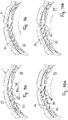
- the Figures 9a and 9b show the effect of the structures 18 in use of the mechanical seal.
- the sealing ring 2 (not shown) rotates in the direction of the arrow 38, with a part of the medium to be sealed getting from the pressure area 22 into the inflow channels 20 of the sealing ring 1, indicated by arrows.
- This medium forms a hydraulic cushion in the sealing gap formed by the abutting sealing surfaces 3, 4, as a result of which the sealing rings 1, 2 lift off slightly from one another.
- the friction on the sealing surfaces 3, 4 is significantly reduced. Since the inflow channels 20 are surrounded on the outside towards the leakage side 23 by the outflow channel 24, the medium flows from the inflow channels 20 into the outflow channel 24. It conveys the medium back into the pressure area 22, as indicated by the flow arrows drawn in. This eliminates the leakage kept very low, since the outflow channel 24 can completely absorb the medium supplied from the inflow channels 20 .
- outflow channels 24 of the structures 18 overlap in the circumferential direction, it is ensured that the medium from the inflow channels 22 does not get out into the leakage area 23 but is instead taken up by the outflow channels 24 and returned to the pressure area 22 .
- part of the medium emerging from the inflow channels 20 can be conveyed back to the pressure area 22 on the sealing surface 3 along the side of the outflow channel 24 facing the pressure area 22 .
- the outflow channel 24 is separated from the medium side to be sealed (pressure area 22), when the sealing ring 2 rotates in the opposite direction, the medium does not enter the sealing gap between the two sealing surfaces 3, 4, which would lead to leakage.
- the reverse direction of rotation occurs, for example, when reversing the vehicle, as in the Figures 10a and 10b shown.
- the medium reaches the wider end of the outflow channels 24 and is conveyed back into the pressure area 22 via the inflow channels 20, as shown by the flow arrows drawn in.
- the mechanical seal with the sealing rings 1, 2 is particularly suitable for use at high speeds or high peripheral speeds.
- Such high rotational speeds/peripheral speeds are in the range of approximately greater than 8,000 rpm, usually around 12,000 to 16,000 rpm. In special cases, speeds/peripheral speeds of around 25,000 rpm are even possible.
- the mechanical seal is particularly suitable in the field of e-mobility, where such high speeds are common.
- the medium to be sealed rests against the inner diameter 21 of the sliding surface.
- the medium to be sealed can also lie against the outer diameter 25 of the sliding surface.
Landscapes
- Engineering & Computer Science (AREA)
- General Engineering & Computer Science (AREA)
- Mechanical Engineering (AREA)
- Mechanical Sealing (AREA)
Abstract
Description
- Die Erfindung betrifft einen Dichtring einer Gleitringdichtung nach dem Oberbegriff des Anspruches 1 sowie eine Gleitringdichtung mit einem solchen Dichtring nach Anspruch 20 bzw. 21.
- Es sind Gleitringdichtungen bekannt, deren beide Dichtringe in Form eines Gleit- und eines Gegenringes aus porösem Material bestehen. Die beiden Dichtringe liegen unter Bildung eines Dichtspaltes mit ihren Dichtflächen aneinander. Die Poren in den Dichtflächen der Dichtringe ermöglichen den Zutritt des abzudichtenden Mediums in den Dichtspalt, wodurch die Dichtringe bei relativer Drehung zueinander geringfügig voneinander abheben.
- Üblicherweise befindet sich das abzudichtende Medium am Außendurchmesser der Dichtringe. Werden solche Gleitringdichtungen für Anwendungen mit hohen Drehzahlen/Umfangsgeschwindigkeiten vorgesehen, wie sie insbesondere bei der E-Mobilität üblich sind, stoßen solche Gleitringdichtungen mit porösem Material an ihre Grenzen. Bei den hohen Drehzahlen, die größer etwa 8.000 1/min sind, üblicherweise zwischen etwa 12.000 bis 16.000 1/min und in Sonderfällen bei etwa 25.000 1/min liegen, treten höhere Reibmomente, eine verringerte Schmierung im Dichtspalt sowie ein nicht mehr zulässiges Leckageverhalten auf. Dies ist insbesondere in Kombination mit einem abzudichtenden Medium zu sehen, das am Innendurchmesser der Dichtringe vorhanden ist.
- Um diesem Problem zu begegnen, ist es bekannt, in die Dichtfläche zumindest des einen Dichtringes gezielt Strömungskanäle einzubringen. Sie haben allerdings den Nachteil, dass entweder die Leckage oder die Reibung hoch sind.
- Wenn die Strukturen in den Dichtflächen keine richtungsabhängige gerichtete Gestalt haben, dann sind solche Dichtringe für beide Drehrichtungen der Dichtringe geeignet. Allerdings haben solche nicht gerichteten Strukturen Performance-Nachteile gegenüber gerichteten Strukturen. Mit solchen nicht gerichteten Strukturen ist zwar der Einsatz in beide Drehrichtungen der Gleitringe möglich, jedoch tritt hierbei erhöhte Leckage auf, und zwar in beiden Drehrichtungen der Dichtringe. Zudem zeigen sich verschlechterte Reibungseigenschaften im Vergleich zu drehrichtungsabhängig gestalteten Strukturen.
- Der Erfindung liegt daher die Aufgabe zugrunde, den gattungsgemäßen Dichtring sowie die Gleitringdichtung so auszubilden, dass einerseits ein optimales Reibungsverhalten und andererseits eine nur geringe Leckage erreicht werden.
- Diese Aufgabe wird beim gattungsgemäßen Dichtring erfindungsgemäß mit den kennzeichnenden Merkmalen des Anspruches 1 und bei den Gleitringdichtungen erfindungsgemäß mit den Merkmalen der Ansprüche 20 und 21 gelöst.
- Beim erfindungsgemäßen Dichtring hat der Ausströmkanal keine Verbindung zur abzudichtenden Mediumsseite und zur Leckageseite. Der Einströmkanal, der mit der abzudichtenden Mediumsseite verbunden ist, ist ebenfalls ohne Verbindung zur Leckageseite. Durch eine solche strukturelle Gestaltung der Dichtfläche des Dichtringes wird erreicht, dass einerseits ausreichend Medium in den Dichtspalt zwischen den beiden Dichtringen einer Gleitringdichtung gelangen kann, so dass ein hervorragendes Reibverhalten erreicht wird. Zum anderen sorgt der Ausströmkanal dafür, dass über den Einströmkanal in Richtung auf die Leckageseite gelangendes abzudichtendes Medium aufgefangen und wieder zurück in den Bereich des abzudichtenden Mediums geführt wird. Dadurch wird eine nur geringe Leckage erzielt.
- Der erfindungsmäße Dichtring zeichnet sich dadurch aus, dass er zwei gegensätzliche Anforderungen optimal erfüllt: eine geringe Reibung und nur wenig Leckage.
- Vorteilhaft ist der Ausströmkanal auf der von der abzudichtenden Mediumsseite abgewandten Seite des Einströmkanales vorgesehen. Dadurch ist sichergestellt, dass das in den Einströmkanal gelangende Medium vor dem Austritt an der Leckageseite in den Ausströmkanal gelangt und von ihm wieder zurück auf die abzudichtende Mediumsseite geleitet wird.
- Vorteilhaft verläuft der Ausströmkanal unter einem Winkel zur Umfangsrichtung der Dichtfläche. So kann der Ausströmkanal so in der Dichtfläche angeordnet sein, dass er sich von einem Ende aus in Richtung auf die abzudichtende Mediumsseite erstreckt. Dadurch wird sichergestellt, dass das zurückzuführende Medium weg von der Leckageseite in Richtung auf die abzudichtende Mediumsseite gefördert wird.
- Der Ausströmkanal hat vorteilhaft Abstand vom Einströmkanal. Dies erschwert zusätzlich, dass das im Einströmkanal befindliche Medium zur Leckageseite gelangt.
- Der Einströmkanal verläuft bei einer vorteilhaften Ausführungsform geneigt in Bezug auf eine durch sein inneres Ende verlaufende Tangentiale. Dadurch wird eine gerichtete Struktur des Einströmkanales gewährleistet, wodurch eine gezielte Beeinflussung der Strömung im Dichtspalt sichergestellt ist. Der gerichtete Verlauf des Einströmkanales ermöglicht einen hohen Eintrag des abzudichtenden Mediums in den Dichtspalt einer Gleitringdichtung und damit des Aufbaues eines entsprechenden hydrostatischen und/oder hydrodynamisches Druckes, wodurch die Reibung vermindert wird. Die damit verbundene Erhöhung der Leckage wird dadurch aufgefangen, dass das Medium in den Ausströmkanal gelangt, der das Medium wieder zurück zur abzudichtenden Mediumsseite führt.
- Eine optimale Rückführung des Mediums in Richtung auf die abzudichtende Mediumsseite ergibt sich, wenn der Ausströmkanal von einem Ende ausgehend in Richtung auf sein anderes Ende sich verbreiternd ausgebildet ist. Dieses andere Ende des Ausströmkanales liegt näher bei der abzudichtenden Mediumsseite als das andere Ende des Ausströmkanales. Die Verbreiterung des Ausströmkanales stellt sicher, dass das Medium zuverlässig in die Mediumsseite zurückgeführt wird. Die Breite des Ausströmkanales kann auch konstant sein, oder sich zum anderen Ende des Ausströmkanales verschmälern.
- Die Verbreiterung des Ausströmkanales kann stetig, aber auch stufenweise erfolgen, je nach Anwendungsfall des Dichtringes.
- Der Einströmkanal und der Ausströmkanal haben vorteilhaft gleiche Tiefe.
- Je nach Einsatzbedingung ist es aber auch möglich, dass der Einströmkanal und der Ausströmkanal unterschiedlich tief sind.
- Vorteilhaft ist die Breite des Einströmkanales größer als dessen Tiefe. Dies trägt zu einer optimalen Funktionalität des Dichtringes wesentlich bei.
- Der Einströmkanal und der Ausströmkanal sind vorteilhaft durch einen Teil der Dichtfläche voneinander getrennt, wobei der radiale Abstand zwischen dem Einströmkanal und dem Ausströmkanal größer als etwa 0,1 mm ist.
- Der Einströmkanal und/oder der Ausströmkanal sind vorteilhaft als flache Nuten ausgebildet. Dies trägt dazu bei, dass einerseits ausreichend Medium in den Dichtspalt gelangen kann, dass aber ein zu starker Austritt des Mediums in Richtung auf die Leckageseite vermieden wird.
- Die Tiefe des Einströmkanales und/oder des Ausströmkanales liegt in einem Bereich zwischen 0 bis etwa 100 µm, vorzugsweise zwischen 0 und etwa 50 µm, insbesondere zwischen etwa 6 µm und etwa 50 µm.
- Das Strömungsverhalten in den Kanälen wird in vorteilhafter Weise günstig beeinflusst, wenn der Einströmkanal und/oder der Ausströmkanal geneigt verlaufende Seitenwände haben. Der Neigungswinkel, bezogen auf die Dichtfläche, ist vorteilhaft kleiner etwa 90°.
- Bei einer weiteren erfindungsgemäßen Ausbildung ist das Volumen des Einströmkanales kleiner als das Volumen des Ausströmkanales. Unter Volumen ist der aus der Dichtfläche zur Bildung der Kanäle entfernte Materialanteil zu verstehen.
- Der Ein- und/oder Ausströmkanal können konstante oder auch nicht konstante Tiefe haben, je nach Einsatzfall.
- Die erfindungsgemäße Gleitringdichtung zeichnet sich dadurch aus, dass sie mit einem erfindungsgemäßen Dichtring versehen ist.
- Bei einer anderen erfindungsgemäßen Ausbildung ist die Gleitringdichtung so ausgebildet, dass der eine Dichtring den wenigstens einen Einströmkanal und der andere Dichtring den wenigstens einen Ausströmkanal aufweisen. Bei einer solchen Ausbildung sind die unterschiedlichen Kanäle auf die beiden Dichtringe verteilt.
- Der Anmeldungsgegenstand ergibt sich nicht nur aus dem Gegenstand der einzelnen Patentansprüche, sondern auch durch alle in den Zeichnungen und der Beschreibung offenbarten Angaben und Merkmale. Sie werden, auch wenn sie nicht Gegenstand der Ansprüche sind, als erfindungswesentlich beansprucht, soweit sie einzeln oder in Kombination gegenüber dem Stand der Technik neu sind.
- Weitere Merkmale der Erfindung ergeben sich aus den weiteren Ansprüchen, der Beschreibung und den Zeichnungen.
- Die Erfindung wird anhand einer in der Zeichnung dargestellten Ausführungsform näher erläutert. Es zeigen
- Fig. 1
- in einem Axialhalbschnitt eine erfindungsgemäße Gleitringdichtung,
- Fig. 2
- eine Ansicht eines erfindungsgemäßen Dichtringes der erfindungsgemäßen Gleitringdichtung gemäß
Fig. 1 , - Fig. 3
- einen Schnitt längs der Linie A-A in
Fig. 2 , - Fig. 4
- den Ausschnitt Z in
Fig. 2 in vergrößerter Darstellung, - Fig. 5
- einen Schnitt längs der Linie B-B in
Fig. 4 , - Fig. 6
- in vergrößerter Darstellung einen Schnitt längs der Line C-C in
Fig. 4 , - Fig. 7
- in vergrößerter Darstellung einen Schnitt längs der Line D-D in
Fig. 4 , - Fig. 8
- in vergrößerter Darstellung einen Schnitt längs der Line E-E in
Fig. 4 , - Fig. 9a und 9b
- jeweils in vergrößerter Darstellung die Strömungsverhältnisse in der Dichtfläche des erfindungsgemäßen Dichtringes beim Drehen in einer Richtung,
- Fig. 10a und 10b
- in Darstellungen entsprechend den
Fig. 9a und 9b die Strömungsverhältnisse beim Drehen des Dichtringes in der umgekehrten Richtung. - Die Gleitringdichtung zeichnet sich dadurch aus, dass sie einen optimalen Kompromiss aus minimaler Leckage und minimaler Reibung aufweist.
- In
Fig. 1 ist eine mögliche Ausführungsform einer Gleitringdichtung beispielhaft dargestellt. Sie kann abweichend vom dargestellten Ausführungsbeispiel jeden anderen geeigneten Aufbau haben. Die Gleitringdichtung hat zwei Dichtringe 1, 2, von denen der Dichtring 1 als Gleitring drehfest angeordnet ist, während der Dichtring 2 als Gegenring drehfest mit der abzudichtenden Welle verbunden und gegenüber dem Dichtring 1 im Einsatz drehbar ist. Die beiden Dichtringe 1, 2 haben aneinander liegende Dichtfläche 3, 4, die in eine Radialebene der Gleitringdichtung liegen und einen Dichtspalt bilden. - Der Dichtring 1 liegt unter Axialkraft mit seiner Dichtfläche 3 an der Dichtfläche 4 des Dichtringes 2 an. Die Axialkraft wird durch wenigstens eine Feder 5 erreicht, die auf den Dichtring 1 eine maximale Kraft ausübt, so dass er dichtend am Dichtring 2 anliegt.
- Die Feder 5 wird beispielhaft durch Tellerfedern gebildet, die sich axial an einem Gehäuse 6 abstützen, das in eine Einbauöffnung 7 eines Aggregates 8 in bekannter Weise eingepresst wird.
- Das Gehäuse 6 hat einen zylindrischen Abschnitt 9, mit dem das Gehäuse 6 unter Presssitz in der Einbauöffnung 7 gehalten ist. Die Feder 5 stützt sich an einem radial verlaufenden Anschlag 10 axial ab.
- Um Dichtring 1 und Dichtring 2 dichtend aneinander anliegen zu lassen, stützt sich die Feder 5 zudem an einer Hülse 39 ab. Sie nimmt den Dichtring 1 über einen elastischen Presssitz auf. Dazu ist ein elastomeres Bauteil 40 zwischen der Hülse 39 und dem Dichtring 1 angeordnet. Das elastomere Bauteil 40 bildet eine statische Abdichtung gegenüber dem abzudichtenden Medium und ist mittels Klemmung zwischen dem Gehäuse 6 und einem Haltering 11 fixiert.
- Der Dichtring 1 ist im Haltering 11 untergebracht, der mit einem zylindrischen Mantel 12 unter Pressung an der Innenseite des Abschnittes 9 des Gehäuses 6 anliegt. Der Dichtring 1 wird vom Haltering 11 axial geführt und gegen ein Verdrehen gesichert.
- Um die Axialbeweglichkeit des Dichtringes 1 zu gewährleisten, ist er an seiner äußeren Umfangsseite mit axialen Vertiefungen 13 versehen (
Fig. 2 ), in die axiale Führungsteile 14 des Halteringes 11 eingreifen (Fig. 1 ). - Der Dichtring 2 ist in einem Haltering 15 aufgenommen, der in bekannter Weise drehfest auf der Welle 16 sitzt. Der Dichtring 2 ist über eine Haltemanschette 17 mit dem Haltering 15 drehfest verbunden. Die Haltemanschette 17 umgibt den Dichtring 2 an seiner Innenseite sowie an seiner vom Dichtring 1 abgewandten Außenseite (
Fig. 1 ) und besteht vorteilhaft aus elastomeren Material, um eine statische Abdichtung gegenüber dem abzudichtendem Medium zu gewährleisten. - Einer der beiden Dichtringe 1, 2 ist in seiner Dichtfläche 3, 4 mit einer Struktur 18 versehen, die nachfolgend im Einzelnen beschrieben wird. Im Folgenden wird davon ausgegangen, dass die Struktur 18 am Dichtring 1 vorgesehen ist. Sie kann aber auch am Dichtring 2 vorhanden sein.
- Der Dichtring 1 hat an seiner äußeren Umfangsfläche radial vorstehende Rippen 19, die sich vorteilhaft über die axiale Breite der äußeren Mantelfläche des Dichtringes 1 erstrecken. Zwischen den Rippen 19 sind die Vertiefungen 13 vorgesehen (
Fig. 2 und4 ). - Die ringförmige Dichtfläche 3 ist eben ausgebbildet und mit der Struktur 18 versehen. Die Strukturen 18 sind, wie aus
Fig. 2 hervorgeht, über den Umfang des Dichtringes 1 verteilt angeordnet. - Anhand von
Fig. 4 wird die eine dieser Strukturen 18 näher beschrieben. Sie weist Einströmkanäle 20 auf, die in Umfangsrichtung des Dichtringes 1 mit Abstand hintereinander angeordnet sind. Die inneren Enden der Einströmkanäle 20 stehen mit einem Druckbereich 22 (Mediumsbereich) in Verbindung, der von einem Gleitflächeninnendurchmesser 21 des Dichtringes 1 begrenzt ist. Der Druckbereich 22 ist durch den Dichtring 1 von einem Leckagebereich 23 getrennt, der beispielsweise die Atmosphäre ist. - Die Dichtflächen 3, 4 der Dichtringe 1, 2 sind über jeweils eine Fase mit der Ober- und der Unterseite der Dichtringe 1, 2 verbunden.
- Die Struktur 18 weist außer den Einströmkanälen 20 einen Ausströmkanal 24 auf, der sich beispielhaft über einen Winkelbereich von 60° erstrecken kann. Der Ausströmkanal 24 erstreckt sich in Umfangsrichtung des Dichtringes 1, wobei seine radiale Breite von einem Ende zum anderen Ende stetig zunimmt.
- Der Ausströmkanal 24 ist so in der Dichtfläche 3 angeordnet, dass sein schmaleres Ende größeren Abstand vom Druckbereich 22 hat als sein anderes, breites Ende. Der Ausströmkanal 24 hat radialen Abstand vom inneren Gleitflächendurchmesser 21 des Dichtringes 1 und damit keine Verbindung zum Druckbereich 22. Die Kanäle 20, 24 haben darüber hinaus Abstand vom äußeren Gleitflächendurchmesser 25 des Dichtringes 1, von der die Rippen 19 radial abstehen. Die Kanäle 20, 24 sind somit nicht mit dem Leckagebereich 23 verbunden. Der Ausströmkanal 24 ist derart in der Dichtfläche 3 vorgesehen, dass sein schmaleres Ende geringeren Abstand vom äußeren Gleitflächendurchmesser 25 hat als sein breites Ende.
- Wie aus den
Fig. 2 und4 hervorgeht, sind die Strukturen 18 über den Umfang der Dichtfläche 3 so vorgesehen, dass das schmale Ende des Ausströmkanales 24 jeweils das breite Ende des Ausströmkanales 24 der benachbarten Struktur 18 übergreift. Dadurch wird erreicht, dass über den Umfang der Dichtfläche 3 eine gleichmäßige Funktion der Strukturen 18 gewährleistet ist. - Da der Ausströmkanal 24 über seine Länge sich stetig dem inneren Gleitflächendurchmesser 21 nähert, haben die Einströmkanäle 20 in Umfangsrichtung zunehmend kleinere Länge.
- Die Einströmkanäle 20 liegen unter einem Winkel α zu einer durch das radial innere Ende des Einströmkanales 20 verlaufenden Tangentialen 26 (
Fig. 4 ). - Wie aus
Fig. 4 hervorgeht, haben die Einströmkanäle 20 jeweils geringen Abstand vom Ausströmkanal 24. Vorteilhaft haben alle Einströmkanäle 20 den gleichen Abstand vom Ausströmkanal 24. Je nach Anwendungsfall können auch unterschiedliche Abstände eingestellt werden. - Der Neigungswinkel α der Einströmkanäle 20 ist ≤ 90° und beträgt vorteilhaft weniger als 60°. Besonders vorteilhaft ist ein Neigungswinkel α von weniger als 45°. Die Neigungswinkel α der Einströmkanäle 20 kann bei allen Einströmkanälen 20 gleich oder verschieden sein.
- Der radiale Abstand 27 (
Fig. 7 ) zwischen den Einströmkanälen 20 und dem Ausströmkanal 24 liegt in einem Bereich vorteilhaft ≥ 1/10 mm. - Die Einströmkanäle 20 und der Ausströmkanal 24 werden jeweils durch Vertiefungen in der Dichtfläche 3 gebildet.
- Wie aus
Fig. 5 hervorgeht, hat der Ausströmkanal 24 zwei stumpfwinklig zueinander liegende Seitenflächen 28, 29, von denen die dem Leckagebereich 23 zugewandte Seitenfläche 28 wesentlich kürzer ist als die dem Mediumsbereich 22 zugewandte Seitenfläche 29, bezogen auf die Radialrichtung des Dichtringes 1. Die Seitenfläche 28 schließt darum unter einem größeren Winkel an die Dichtfläche 3 an als die flacher verlaufende Seitenfläche 29. Der Neigungswinkel β der Seitenflächen 28, 29 bezüglich der Dichtfläche 3 ist kleiner als 90°, vorteilhaft ≤ 60°. Besonders vorteilhaft ist es, wenn der Neigungswinkel β kleiner etwa 40° ist. - Der Neigungswinkel der Seitenflächen 28, 29 kann gleich oder verschieden sein.
- Wie aus
Fig. 5 weiter hervorgeht, ist die Breite 30 des Ausströmkanales 24 größer als dessen maximale, in radialer Richtung gemessene Tiefe 31. Das Verhältnis von Breite 30 zu Tiefe 31 des Ausströmkanales 24 ist somit größer als 1. -
Fig. 5 zeigt die Querschnittsausbildung des Ausströmkanales 24 nahe seinem breiteren Ende. Die den Ausströmkanal 24 endseitig begrenzende Wand 32 (Fig. 4 ) verläuft parallel zur inneren Umfangsfläche 21 des Dichtringes 1. - Mit Abstand vom breiteren Ende des Ausströmkanales 24 ändert sich die Querschnittsform, wie aus
Fig. 6 hervorgeht. Die Seitenfläche 28 ist mit der Seitenfläche 29 über einen ebenen Boden 32 verbunden, der parallel zur Dichtfläche 3 verläuft. Vorteilhaft haben die Seitenflächen 28, 29 in diesem Bereich des Ausströmkanales 24 den gleichen Neigungswinkel β bezüglich der Dichtfläche 3. - Die Einströmkanäle 20 haben eine ähnliche Querschnittsgestaltung wie der Ausströmkanal 24. Wie
Fig. 7 zeigt, haben die Einströmkanäle 20 unter dem Neigungswinkel β zur Dichtfläche 3 geneigt verlaufende Seitenflächen 33, 34, die durch einen vorteilhaft parallel zur Dichtfläche 3 verlaufenden Boden 35 miteinander verbunden sind. Im Unterschied zum Ausströmkanal 24 ändert sich die Querschnittsform der Einströmkanäle 20 über ihre Länge nicht. - In vorteilhafter Weise haben die Seitenflächen 33, 34 den gleichen Neigungswinkel β in Bezug auf die Dichtfläche 3.
- Auch bei den Einströmkanälen 20 ist vorgesehen, dass die Breite 36 größer ist als die Tiefe 37.
- Im dargestellten Ausführungsbeispiel ist die Breite 30, 36 der Ausström- und Einströmkanäle um ein Mehrfaches größer als deren Tiefe 31, 37.
- Die Einströmkanäle 20 und/oder der Ausströmkanal 24 der Struktur 18 können konstante Tiefe haben. Je nach Anwendungsbereich können die Kanäle 20, 24 so ausgebildet sein, dass sich ihre Tiefe 31, 37 kontinuierlich oder schrittweise verändert.
- Ein Beispiel für die schrittweise Veränderung der Tiefe zeigt
Fig. 8 . Im dargestellten und beschriebenen Ausführungsbeispiel ist diese Gestaltung im Bereich des schmalen Endes des Ausströmkanales 24 vorgesehen. Beginnend von der Dichtfläche 3 nimmt die Tiefe des Ausströmkanales 24 schrittweise zu. Eine derartige Tiefengestaltung kann auch bei den Einströmkanälen 20 vorgesehen sein. - Je nach Anwendungsfall der Gleitringdichtung können die Einströmkanäle 20 und der Ausströmkanal 24 der Struktur 18 gleich tief sein. Es ist selbstverständlich möglich, dass die Einströmkanäle 20 und der Ausströmkanal 24 unterschiedliche Tiefe haben.
- Die Einströmkanäle 20 und der Ausströmkanal 24 sind durch verhältnismäßig flache Nuten gebildet. Ihre Tiefe liegt in einem Bereich von 0 bis etwa 100 µm, vorteilhaft in einem Bereich zwischen 0 und etwa 50 µm. Ein besonders vorteilhafter Tiefenbereich liegt bei etwa 6 bis etwa 50 µm. Die Einströmkanäle 20 sind so auf der Dichtfläche 3 vorgesehen, dass sich ihre inneren Enden, in Achsrichtung des Dichtringes 1 gesehen, auf einem zur Achse des Dichtringes koaxialen Kreis befinden (
Fig. 4 ). Da sich der Ausströmkanal 24 in Richtung auf den Druckbereich 22 nähert, nimmt die Länge der Einströmkanäle 20 in Richtung auf das breitere Ende des Ausströmkanales 24 ab. - Beim dargestellten bevorzugten Ausführungsbeispiel sind die Einströmkanäle 20 und der Ausströmkanal 24 auf der Dichtfläche 3 des Dichtringes 1 vorgesehen. Es besteht aber auch die Möglichkeit, die Einströmkanäle 20 beispielsweise auf der Dichtfläche 3 des Dichtringes 1 und den Ausströmkanal 24 auf der Dichtfläche 4 des anderen Dichtringes 2 vorzusehen.
- Die Dichtringe 1, 2 bestehen vorteilhaft aus einem harten Material, insbesondere aus SiC. Auch andere harte Materialien, wie Stahl oder Edelstahl, kommen in Betracht.
- Grundsätzlich ist es auch möglich, dass die beiden Dichtringe 1, 2 aus unterschiedlichen Materialien bestehen. Hier können hart-weich-Paarungen zum Einsatz kommen. Bespielhaft kann ein harter Dichtring 1,2 aus SIC mit einem weichen Dichtring 1, 2 aus Kohlewerkstoff gepaart werden. Vorteilhaft ist die Struktur auf dem Dichtring 1, 2 aus hartem Werkstoff vorgesehen.
- Der Ausströmkanal 24 verbreitert sich im dargestellten Ausführungsbeispiel kontinuierlich. Er kann aber auch schrittweise in Richtung auf das abzudichtende Medium (Druckbereich 22) stufenweise in seiner Breite zunehmen. Der Ausströmkanal kann aber auch konstante Breite haben, oder sich in Richtung auf das abzudichtende Medium (Druckbereich 22) verjüngen.
- Zur Herstellung der als Vertiefungen ausgebildeten Einströmkanäle 20 und Ausströmkanal 24 können übliche Herstellungsverfahren eingesetzt werden, wie beispielsweise ein Laserprozess oder - bei metallischem Material - ein PCM-Verfahren.
- Um eine optimale Funktion des Dichtringes 1 zu erhalten, sind die Einströmkanäle 20 und der Ausströmkanal 24 der Struktur 18 so in der Dichtfläche 3 vorgesehen, dass das Volumen der Vertiefungen der Einströmkanäle 20 geringer ist als das Volumen des Ausströmkanales 24. Das Verhältnis des aus der Dichtfläche 3 entfernten Volumenmaterials der Einströmkanäle 20 zum Ausströmkanal 24 ist somit kleiner als 1. Durch diese Gestaltung der Struktur 18 wird erreicht, dass das von den Einströmkanälen 20 aufgenommene abzudichtende Medium auf jeden Fall vollständig über den Ausströmkanal 24 zurück zum Druckbereich 22 gefördert wird.
- Die
Figuren 9a und 9b zeigen die Wirkung der Strukturen 18 im Einsatz der Gleitringdichtung. Der (nicht dargestellte) Dichtring 2 dreht in Richtung des Pfeiles 38, wobei, durch Pfeile angedeutet, ein Teil des abzudichtenden Mediums aus dem Druckbereich 22 in die Einströmkanäle 20 des Dichtringes 1 gelangt. Dieses Medium bildet in dem durch die aneinander liegenden Dichtflächen 3, 4 gebildeten Dichtspalt ein Hydraulikpolster aus, wodurch die Dichtringe 1, 2 geringfügig voneinander abheben. Dadurch wird die Reibung an den Dichtflächen 3, 4 wesentlich herabgesetzt. Da die Einströmkanäle 20 nach außen zur Leckageseite 23 vom Ausströmkanal 24 umgeben werden, gelangt das Medium aus den Einströmkanälen 20 in den Ausströmkanal 24. Er fördert das Medium, wie durch die eingezeichneten Strömungspfeile kenntlich gemacht, zurück in den Druckbereich 22. Dadurch wird die Leckage sehr gering gehalten, da der Ausströmkanal 24 das aus den Einströmkanälen 20 zugeführte Medium vollständig aufnehmen kann. - Da die Ausströmkanäle 24 der Strukturen 18 in Umfangsrichtung einander überlappen, ist gewährleistet, dass das Medium aus den Einströmkanälen 22 nicht nach außen in den Leckagebereich 23 gelangt, sondern von den Ausströmkanälen 24 aufgenommen und zum Druckbereich 22 zurückgeführt wird.
- Wie aus
Fig. 9b hervorgeht, kann ein Teil des aus den Einströmkanälen 20 austretenden Mediums auf der Dichtfläche 3 längs der dem Druckbereich 22 zugewandten Seite des Ausströmkanales 24 zurück zum Druckbereich 22 gefördert werden. - Da der Ausströmkanal 24 von der abzudichtenden Mediumsseite (Druckbereich 22) getrennt ist, erfolgt bei einer umgekehrten Drehrichtung des Dichtringes 2 kein Eintrag des Mediums in den Dichtspalt zwischen den beiden Dichtflächen 3, 4, der zur Leckage führen würde. Die umgekehrte Drehrichtung tritt beispielsweise bei einer Rückwärtsfahrt des Fahrzeuges auf, wie in den
Fig. 10a und 10b dargestellt. Das Medium gelangt bei der Rückwärtsfahrt in das breitere Ende der Ausströmkanäle 24 und wird über die Einströmkanäle 20 zurück in den Druckbereich 22 gefördert, wie die eingezeichneten Strömungspfeile zeigen. - Die Trennung der Ausströmkanäle 24 von der abzudichtenden Mediumsseite 22 erzeugt außerdem bei Drehung des Dichtringes 2 in Vorzugsrichtung (
Fig. 9a und 9b ) eine hydrodynamische Druckwirkung, die öffnend auf den Dichtspalt zwischen den Dichtflächen 3, 4 wirkt. Dies wirkt sich zusätzlich vorteilhaft auf eine verringerte Reibung aus. - Die Gleitringdichtung mit den Dichtringen 1, 2 ist zum Einsatz bei hohen Drehzahlen bzw. hohen Umfangsgeschwindigkeiten besonders geeignet. Solche hohen Drehzahlen/Umfangsgeschwindigkeiten liegen im Bereich von etwa größer 8.000 1/min, üblicherweise bei etwa 12.000 bis 16.000 1/min. In Sonderfällen sind sogar Drehzahlen/Umfangsgeschwindigkeiten in der Größenordnung von etwa 25.000 1/min möglich. Die Gleitringdichtung ist insbesondere im Bereich der E-Mobilität hervorragend geeignet, wo solche hohen Drehzahlen üblich sind.
- Bei den Ausführungsbeispielen der
Fig. 1 bis 10b liegt das abzudichtende Medium (Druckbereich 22) am inneren Gleitflächendurchmesser 21 an. Das abzudichtende Medium kann aber ebenso am äußeren Gleitflächendurchmesser 25 anliegen.
Claims (21)
- Dichtring einer Gleitringdichtung, mit einer Dichtfläche (3, 4), in der wenigstens eine Förderstruktur (18) vorgesehen ist, die wenigstens einen Einströmkanal (20) und wenigstens einen Ausströmkanal (24) aufweist, wobei der Einströmkanal (20) mit einer abzudichtenden Mediumsseite verbunden ist, die durch den Dichtring (1, 2) von einer Leckageseite (23) getrennt ist,
dadurch gekennzeichnet, dass der Ausströmkanal (24) ohne Verbindung zur abzudichtenden Mediumsseite (22) und zur Leckageseite (23) und der Einströmkanal (20) ohne Verbindung zur Leckageseite (23) sind. - Dichtring nach Anspruch 1,
dadurch gekennzeichnet, dass der Ausströmkanal (24) auf der von der abzudichtenden Mediumsseite (22) abgewandten Seite des Einströmkanales (20) vorgesehen ist. - Dichtring nach Anspruch 1 oder 2,
dadurch gekennzeichnet, dass der Ausströmkanal (24) unter einem Winkel zur Umfangsrichtung der Dichtfläche verläuft. - Dichtring nach einem der Ansprüche 1 bis 3,
dadurch gekennzeichnet, dass der Ausströmkanal (24) Abstand vom Einströmkanal (20) hat. - Dichtring nach einem der Ansprüche 1 bis 4,
dadurch gekennzeichnet, dass der Einströmkanal (20) geneigt in Bezug auf eine durch sein inneres Ende verlaufende Tangentiale (26) angeordnet ist. - Dichtring nach einem der Ansprüche 1 bis 5,
dadurch gekennzeichnet, dass der Ausströmkanal (24) von einem Ende ausgehend in Richtung auf sein anderes Ende sich verbreiternd ausgebildet ist. - Dichtring nach Anspruch 6,
dadurch gekennzeichnet, dass sich der Ausströmkanal (24) stetig verbreitert. - Dichtring nach Anspruch 6,
dadurch gekennzeichnet, dass sich der Ausströmkanal (24) stufenweise verbreitert. - Dichtring nach einem der Ansprüche 1 bis 8,
dadurch gekennzeichnet, dass der Einströmkanal (20) und der Ausströmkanal (24) gleiche Tiefe haben. - Dichtring nach einem der Ansprüche 1 bis 8,
dadurch gekennzeichnet, dass der Einströmkanal (20) und der Ausströmkanal (24) unterschiedliche Tiefe haben. - Dichtring nach einem der Ansprüche 1 bis 10.
dadurch gekennzeichnet, dass die Breite (36) des Einströmkanales (20) größer ist als dessen Tiefe. - Dichtring nach einem der Ansprüche 1 bis 11,
dadurch gekennzeichnet, dass der Einströmkanal (20) und der Ausströmkanal (24) durch einen Teil der Dichtfläche (3, 4) voneinander getrennt sind. - Dichtring nach einem der Ansprüche 1 bis 12,
dadurch gekennzeichnet, dass der Abstand zwischen dem Einströmkanal (20) und dem Ausströmkanal (24) größer als etwa 0,1 mm beträgt. - Dichtring nach einem der Ansprüche 1 bis 13,
dadurch gekennzeichnet, dass der Einströmkanal (20) und/oder der Ausströmkanal (24) eine Tiefe (31, 37) haben, die in einem Bereich zwischen 0 bis etwa 100 µm, vorzugsweise zwischen 0 µm und etwa 50 µm, insbesondere zwischen etwa 6 µm und etwa 50 µm liegt - Dichtring nach einem der Ansprüche 1 bis 14,
dadurch gekennzeichnet, dass der Einströmkanal (20) und/oder der Ausströmkanal (24) geneigt verlaufende Seitenwände (28, 29; 39, 34) haben. - Dichtring nach Anspruch 15,
dadurch gekennzeichnet, dass die Seitenwände (28, 29; 33, 34) unter einem Winkel (β) ≥90° geneigt zur Dichtfläche (3, 4) liegen. - Dichtring, insbesondere nach einem der Ansprüche 1 bis 16,
dadurch gekennzeichnet, dass das Volumen des Einströmkanales (20) kleiner ist als das Volumen des Ausströmkanales (24). - Dichtring nach einem der Ansprüche 1 bis 17,
dadurch gekennzeichnet, dass der Ein- und/oder Ausströmkanal (20, 24) eine konstante Tiefe haben - Dichtring nach einem der Ansprüche 1 bis 17,
dadurch gekennzeichnet, dass der Ein- und/oder Ausströmkanal (20, 24) nicht konstante Tiefe hat. - Gleitringdichtung mit einem Dichtring (1, 2) nach einem der Ansprüche 1 bis 19.
- Gleitringdichtung mit zwei Dichtringen (1, 2), die mit Dichtflächen (3, 4) aneinander liegen und von denen der eine Dichtring den wenigstens einen Einströmkanal (20) und der andere Dichtring den wenigstens einen Ausströmkanal (24) aufweisen.
Applications Claiming Priority (1)
| Application Number | Priority Date | Filing Date | Title |
|---|---|---|---|
| DE102021003139.3A DE102021003139A1 (de) | 2021-06-18 | 2021-06-18 | Dichtring einer Gleitringdichtung sowie Gleitringdichtung mit einem solchen Dichtring |
Publications (2)
| Publication Number | Publication Date |
|---|---|
| EP4105524A1 true EP4105524A1 (de) | 2022-12-21 |
| EP4105524B1 EP4105524B1 (de) | 2025-01-29 |
Family
ID=82067506
Family Applications (1)
| Application Number | Title | Priority Date | Filing Date |
|---|---|---|---|
| EP22179160.1A Active EP4105524B1 (de) | 2021-06-18 | 2022-06-15 | Dichtring einer gleitringdichtung sowie gleitringdichtung mit einem solchen dichtring |
Country Status (3)
| Country | Link |
|---|---|
| EP (1) | EP4105524B1 (de) |
| CN (1) | CN115492932A (de) |
| DE (1) | DE102021003139A1 (de) |
Citations (5)
| Publication number | Priority date | Publication date | Assignee | Title |
|---|---|---|---|---|
| US20180172162A1 (en) * | 2015-06-15 | 2018-06-21 | Eagle Industry Co., Ltd. | Slide component |
| US20190376558A1 (en) * | 2017-01-30 | 2019-12-12 | Eagle Industry Co., Ltd. | Sliding component |
| CN111350824A (zh) * | 2020-02-02 | 2020-06-30 | 江苏大学 | 一种双向似月牙型槽端面双向旋转机械密封结构 |
| CN111473115A (zh) * | 2020-05-13 | 2020-07-31 | 清华大学 | 一种带有副堰区的机械密封端面结构 |
| US20210054935A1 (en) * | 2017-01-30 | 2021-02-25 | Eagle Industry Co., Ltd. | Sliding component |
Family Cites Families (10)
| Publication number | Priority date | Publication date | Assignee | Title |
|---|---|---|---|---|
| JPS6199717A (ja) * | 1984-10-19 | 1986-05-17 | Ebara Corp | 軸受装置 |
| JPH10281299A (ja) * | 1997-04-11 | 1998-10-23 | Mitsubishi Heavy Ind Ltd | メカニカルシール装置 |
| US6152452A (en) | 1997-10-17 | 2000-11-28 | Wang; Yuming | Face seal with spiral grooves |
| CN100427816C (zh) | 2002-09-20 | 2008-10-22 | 徐万福 | 一种由角形微槽族组成的螺旋槽端面机械密封 |
| CN102588600B (zh) * | 2012-02-15 | 2015-04-22 | 浙江工业大学 | 具有回流功能的型槽端面非接触式机械密封 |
| EP2902677B1 (de) | 2012-09-29 | 2018-08-22 | Eagle Industry Co., Ltd. | Schiebeteil |
| WO2016035860A1 (ja) * | 2014-09-04 | 2016-03-10 | イーグル工業株式会社 | メカニカルシール |
| CN109563933B (zh) | 2016-06-10 | 2021-02-26 | 约翰起重机英国有限公司 | 减少排放气体密封件 |
| KR102661123B1 (ko) | 2018-10-24 | 2024-04-29 | 이구루코교 가부시기가이샤 | 슬라이딩 부재 |
| KR102669558B1 (ko) | 2019-04-09 | 2024-05-28 | 이구루코교 가부시기가이샤 | 슬라이딩 부품 |
-
2021
- 2021-06-18 DE DE102021003139.3A patent/DE102021003139A1/de active Pending
-
2022
- 2022-06-15 EP EP22179160.1A patent/EP4105524B1/de active Active
- 2022-06-16 CN CN202210691541.8A patent/CN115492932A/zh active Pending
Patent Citations (5)
| Publication number | Priority date | Publication date | Assignee | Title |
|---|---|---|---|---|
| US20180172162A1 (en) * | 2015-06-15 | 2018-06-21 | Eagle Industry Co., Ltd. | Slide component |
| US20190376558A1 (en) * | 2017-01-30 | 2019-12-12 | Eagle Industry Co., Ltd. | Sliding component |
| US20210054935A1 (en) * | 2017-01-30 | 2021-02-25 | Eagle Industry Co., Ltd. | Sliding component |
| CN111350824A (zh) * | 2020-02-02 | 2020-06-30 | 江苏大学 | 一种双向似月牙型槽端面双向旋转机械密封结构 |
| CN111473115A (zh) * | 2020-05-13 | 2020-07-31 | 清华大学 | 一种带有副堰区的机械密封端面结构 |
Also Published As
| Publication number | Publication date |
|---|---|
| EP4105524B1 (de) | 2025-01-29 |
| CN115492932A (zh) | 2022-12-20 |
| DE102021003139A1 (de) | 2022-12-22 |
Similar Documents
| Publication | Publication Date | Title |
|---|---|---|
| EP1261820B1 (de) | Labyrinthdichtung zwischen drehbaren bauteilen | |
| EP2430323B1 (de) | Wälzlager mit käfig zur verhinderung einer überflutung mit schmiermittel | |
| DE102007022316B4 (de) | Radial-Nadellager-Baueinheit | |
| WO1997033108A1 (de) | Dichtung für einen ringkolben einer hydraulischen kupplungs-ausrückvorrichtung | |
| EP2403682B1 (de) | Spindel mit einer lanzeneinheit | |
| EP2210005A1 (de) | Axiallager, insbesondere für einen turbolader | |
| DE102009054794A1 (de) | Radiale Drehdurchführung und Buchse hierfür | |
| DE3110294A1 (de) | "anordnung zur befestigung von maschinenteilen o.dgl. auf wellen" | |
| DE19840433B4 (de) | Hydrodynamisches Lager | |
| EP3726104B1 (de) | Radialwellendichtung | |
| EP3810963A1 (de) | Hydrodynamisch wirksamer dichtring und drehdurchführung mit einem solchen dichtring | |
| DE102019133669B4 (de) | Vorrichtung mit einem Bauteil und einem Ventil mit einem Ventilgehäuse des Ventils | |
| EP3502523B1 (de) | Radialwellendichtung | |
| DE9005966U1 (de) | Linearkugellager | |
| DE102006024841B4 (de) | Elktromagnetische Stellvorrichtung | |
| DE102018003830A1 (de) | Reibteil für eine reibschlüssig arbeitende Einrichtung | |
| EP4105524B1 (de) | Dichtring einer gleitringdichtung sowie gleitringdichtung mit einem solchen dichtring | |
| DE2558561C2 (de) | Vorrichtung zur Kontrolle bzw. zur Steuerung der Steifheit der Welle einer Turbomaschine | |
| DE102013224413A1 (de) | Axiallager mit Schmiermittelzuführung für eine schnelllaufende Welle | |
| DE1221865B (de) | Gleitringdichtung | |
| WO2016119787A1 (de) | Gleitlageranordnung für eine mit einer umlaufenden radialkraft belasteten welle | |
| EP4058680B1 (de) | Radlagereinheit | |
| EP1311760A1 (de) | Hydraulische radialkolbenmaschine | |
| DE102017119497A1 (de) | Fluiddynamisches Lagersystem | |
| DE19947435B4 (de) | Anlagering |
Legal Events
| Date | Code | Title | Description |
|---|---|---|---|
| PUAI | Public reference made under article 153(3) epc to a published international application that has entered the european phase |
Free format text: ORIGINAL CODE: 0009012 |
|
| STAA | Information on the status of an ep patent application or granted ep patent |
Free format text: STATUS: THE APPLICATION HAS BEEN PUBLISHED |
|
| AK | Designated contracting states |
Kind code of ref document: A1 Designated state(s): AL AT BE BG CH CY CZ DE DK EE ES FI FR GB GR HR HU IE IS IT LI LT LU LV MC MK MT NL NO PL PT RO RS SE SI SK SM TR |
|
| STAA | Information on the status of an ep patent application or granted ep patent |
Free format text: STATUS: REQUEST FOR EXAMINATION WAS MADE |
|
| STAA | Information on the status of an ep patent application or granted ep patent |
Free format text: STATUS: EXAMINATION IS IN PROGRESS |
|
| 17P | Request for examination filed |
Effective date: 20230621 |
|
| RBV | Designated contracting states (corrected) |
Designated state(s): AL AT BE BG CH CY CZ DE DK EE ES FI FR GB GR HR HU IE IS IT LI LT LU LV MC MK MT NL NO PL PT RO RS SE SI SK SM TR |
|
| 17Q | First examination report despatched |
Effective date: 20230713 |
|
| GRAP | Despatch of communication of intention to grant a patent |
Free format text: ORIGINAL CODE: EPIDOSNIGR1 |
|
| STAA | Information on the status of an ep patent application or granted ep patent |
Free format text: STATUS: GRANT OF PATENT IS INTENDED |
|
| INTG | Intention to grant announced |
Effective date: 20240502 |
|
| GRAS | Grant fee paid |
Free format text: ORIGINAL CODE: EPIDOSNIGR3 |
|
| GRAJ | Information related to disapproval of communication of intention to grant by the applicant or resumption of examination proceedings by the epo deleted |
Free format text: ORIGINAL CODE: EPIDOSDIGR1 |
|
| GRAL | Information related to payment of fee for publishing/printing deleted |
Free format text: ORIGINAL CODE: EPIDOSDIGR3 |
|
| STAA | Information on the status of an ep patent application or granted ep patent |
Free format text: STATUS: EXAMINATION IS IN PROGRESS |
|
| GRAP | Despatch of communication of intention to grant a patent |
Free format text: ORIGINAL CODE: EPIDOSNIGR1 |
|
| STAA | Information on the status of an ep patent application or granted ep patent |
Free format text: STATUS: GRANT OF PATENT IS INTENDED |
|
| INTC | Intention to grant announced (deleted) | ||
| INTG | Intention to grant announced |
Effective date: 20240916 |
|
| GRAA | (expected) grant |
Free format text: ORIGINAL CODE: 0009210 |
|
| STAA | Information on the status of an ep patent application or granted ep patent |
Free format text: STATUS: THE PATENT HAS BEEN GRANTED |
|
| AK | Designated contracting states |
Kind code of ref document: B1 Designated state(s): AL AT BE BG CH CY CZ DE DK EE ES FI FR GB GR HR HU IE IS IT LI LT LU LV MC MK MT NL NO PL PT RO RS SE SI SK SM TR |
|
| REG | Reference to a national code |
Ref country code: GB Ref legal event code: FG4D Free format text: NOT ENGLISH |
|
| REG | Reference to a national code |
Ref country code: CH Ref legal event code: EP |
|
| REG | Reference to a national code |
Ref country code: DE Ref legal event code: R096 Ref document number: 502022002751 Country of ref document: DE |
|
| REG | Reference to a national code |
Ref country code: IE Ref legal event code: FG4D Free format text: LANGUAGE OF EP DOCUMENT: GERMAN |
|
| REG | Reference to a national code |
Ref country code: NL Ref legal event code: MP Effective date: 20250129 |
|
| PG25 | Lapsed in a contracting state [announced via postgrant information from national office to epo] |
Ref country code: NL Free format text: LAPSE BECAUSE OF FAILURE TO SUBMIT A TRANSLATION OF THE DESCRIPTION OR TO PAY THE FEE WITHIN THE PRESCRIBED TIME-LIMIT Effective date: 20250129 |
|
| PG25 | Lapsed in a contracting state [announced via postgrant information from national office to epo] |
Ref country code: RS Free format text: LAPSE BECAUSE OF FAILURE TO SUBMIT A TRANSLATION OF THE DESCRIPTION OR TO PAY THE FEE WITHIN THE PRESCRIBED TIME-LIMIT Effective date: 20250429 |
|
| PG25 | Lapsed in a contracting state [announced via postgrant information from national office to epo] |
Ref country code: FI Free format text: LAPSE BECAUSE OF FAILURE TO SUBMIT A TRANSLATION OF THE DESCRIPTION OR TO PAY THE FEE WITHIN THE PRESCRIBED TIME-LIMIT Effective date: 20250129 |
|
| PG25 | Lapsed in a contracting state [announced via postgrant information from national office to epo] |
Ref country code: PL Free format text: LAPSE BECAUSE OF FAILURE TO SUBMIT A TRANSLATION OF THE DESCRIPTION OR TO PAY THE FEE WITHIN THE PRESCRIBED TIME-LIMIT Effective date: 20250129 |
|
| PG25 | Lapsed in a contracting state [announced via postgrant information from national office to epo] |
Ref country code: ES Free format text: LAPSE BECAUSE OF FAILURE TO SUBMIT A TRANSLATION OF THE DESCRIPTION OR TO PAY THE FEE WITHIN THE PRESCRIBED TIME-LIMIT Effective date: 20250129 |
|
| REG | Reference to a national code |
Ref country code: LT Ref legal event code: MG9D |
|
| PG25 | Lapsed in a contracting state [announced via postgrant information from national office to epo] |
Ref country code: NO Free format text: LAPSE BECAUSE OF FAILURE TO SUBMIT A TRANSLATION OF THE DESCRIPTION OR TO PAY THE FEE WITHIN THE PRESCRIBED TIME-LIMIT Effective date: 20250429 Ref country code: IS Free format text: LAPSE BECAUSE OF FAILURE TO SUBMIT A TRANSLATION OF THE DESCRIPTION OR TO PAY THE FEE WITHIN THE PRESCRIBED TIME-LIMIT Effective date: 20250529 |
|
| PG25 | Lapsed in a contracting state [announced via postgrant information from national office to epo] |
Ref country code: HR Free format text: LAPSE BECAUSE OF FAILURE TO SUBMIT A TRANSLATION OF THE DESCRIPTION OR TO PAY THE FEE WITHIN THE PRESCRIBED TIME-LIMIT Effective date: 20250129 |
|
| PG25 | Lapsed in a contracting state [announced via postgrant information from national office to epo] |
Ref country code: LV Free format text: LAPSE BECAUSE OF FAILURE TO SUBMIT A TRANSLATION OF THE DESCRIPTION OR TO PAY THE FEE WITHIN THE PRESCRIBED TIME-LIMIT Effective date: 20250129 Ref country code: PT Free format text: LAPSE BECAUSE OF FAILURE TO SUBMIT A TRANSLATION OF THE DESCRIPTION OR TO PAY THE FEE WITHIN THE PRESCRIBED TIME-LIMIT Effective date: 20250529 |
|
| PG25 | Lapsed in a contracting state [announced via postgrant information from national office to epo] |
Ref country code: GR Free format text: LAPSE BECAUSE OF FAILURE TO SUBMIT A TRANSLATION OF THE DESCRIPTION OR TO PAY THE FEE WITHIN THE PRESCRIBED TIME-LIMIT Effective date: 20250430 Ref country code: BG Free format text: LAPSE BECAUSE OF FAILURE TO SUBMIT A TRANSLATION OF THE DESCRIPTION OR TO PAY THE FEE WITHIN THE PRESCRIBED TIME-LIMIT Effective date: 20250129 |
|
| PG25 | Lapsed in a contracting state [announced via postgrant information from national office to epo] |
Ref country code: SE Free format text: LAPSE BECAUSE OF FAILURE TO SUBMIT A TRANSLATION OF THE DESCRIPTION OR TO PAY THE FEE WITHIN THE PRESCRIBED TIME-LIMIT Effective date: 20250129 |
|
| PG25 | Lapsed in a contracting state [announced via postgrant information from national office to epo] |
Ref country code: SM Free format text: LAPSE BECAUSE OF FAILURE TO SUBMIT A TRANSLATION OF THE DESCRIPTION OR TO PAY THE FEE WITHIN THE PRESCRIBED TIME-LIMIT Effective date: 20250129 |
|
| PG25 | Lapsed in a contracting state [announced via postgrant information from national office to epo] |
Ref country code: DK Free format text: LAPSE BECAUSE OF FAILURE TO SUBMIT A TRANSLATION OF THE DESCRIPTION OR TO PAY THE FEE WITHIN THE PRESCRIBED TIME-LIMIT Effective date: 20250129 |
|
| PG25 | Lapsed in a contracting state [announced via postgrant information from national office to epo] |
Ref country code: IT Free format text: LAPSE BECAUSE OF FAILURE TO SUBMIT A TRANSLATION OF THE DESCRIPTION OR TO PAY THE FEE WITHIN THE PRESCRIBED TIME-LIMIT Effective date: 20250129 |
|
| PG25 | Lapsed in a contracting state [announced via postgrant information from national office to epo] |
Ref country code: EE Free format text: LAPSE BECAUSE OF FAILURE TO SUBMIT A TRANSLATION OF THE DESCRIPTION OR TO PAY THE FEE WITHIN THE PRESCRIBED TIME-LIMIT Effective date: 20250129 Ref country code: CZ Free format text: LAPSE BECAUSE OF FAILURE TO SUBMIT A TRANSLATION OF THE DESCRIPTION OR TO PAY THE FEE WITHIN THE PRESCRIBED TIME-LIMIT Effective date: 20250129 |
|
| PG25 | Lapsed in a contracting state [announced via postgrant information from national office to epo] |
Ref country code: RO Free format text: LAPSE BECAUSE OF FAILURE TO SUBMIT A TRANSLATION OF THE DESCRIPTION OR TO PAY THE FEE WITHIN THE PRESCRIBED TIME-LIMIT Effective date: 20250129 |
|
| PG25 | Lapsed in a contracting state [announced via postgrant information from national office to epo] |
Ref country code: SK Free format text: LAPSE BECAUSE OF FAILURE TO SUBMIT A TRANSLATION OF THE DESCRIPTION OR TO PAY THE FEE WITHIN THE PRESCRIBED TIME-LIMIT Effective date: 20250129 |
|
| REG | Reference to a national code |
Ref country code: DE Ref legal event code: R026 Ref document number: 502022002751 Country of ref document: DE |
|
| PLBI | Opposition filed |
Free format text: ORIGINAL CODE: 0009260 |
|
| REG | Reference to a national code |
Ref country code: CH Ref legal event code: L10 Free format text: ST27 STATUS EVENT CODE: U-0-0-L10-L00 (AS PROVIDED BY THE NATIONAL OFFICE) Effective date: 20251105 |
|
| PLAX | Notice of opposition and request to file observation + time limit sent |
Free format text: ORIGINAL CODE: EPIDOSNOBS2 |
|
| 26 | Opposition filed |
Opponent name: WEILNAU, CARSTEN Effective date: 20251027 |
|
| REG | Reference to a national code |
Ref country code: CH Ref legal event code: H13 Free format text: ST27 STATUS EVENT CODE: U-0-0-H10-H13 (AS PROVIDED BY THE NATIONAL OFFICE) Effective date: 20260127 |
|
| PG25 | Lapsed in a contracting state [announced via postgrant information from national office to epo] |
Ref country code: MC Free format text: LAPSE BECAUSE OF FAILURE TO SUBMIT A TRANSLATION OF THE DESCRIPTION OR TO PAY THE FEE WITHIN THE PRESCRIBED TIME-LIMIT Effective date: 20250129 |
|
| PG25 | Lapsed in a contracting state [announced via postgrant information from national office to epo] |
Ref country code: LU Free format text: LAPSE BECAUSE OF NON-PAYMENT OF DUE FEES Effective date: 20250615 |
|
| REG | Reference to a national code |
Ref country code: BE Ref legal event code: MM Effective date: 20250630 |
|
| PLBB | Reply of patent proprietor to notice(s) of opposition received |
Free format text: ORIGINAL CODE: EPIDOSNOBS3 |
|
| PG25 | Lapsed in a contracting state [announced via postgrant information from national office to epo] |
Ref country code: IE Free format text: LAPSE BECAUSE OF NON-PAYMENT OF DUE FEES Effective date: 20250615 |
|
| PG25 | Lapsed in a contracting state [announced via postgrant information from national office to epo] |
Ref country code: BE Free format text: LAPSE BECAUSE OF NON-PAYMENT OF DUE FEES Effective date: 20250630 |
|
| PG25 | Lapsed in a contracting state [announced via postgrant information from national office to epo] |
Ref country code: FR Free format text: LAPSE BECAUSE OF NON-PAYMENT OF DUE FEES Effective date: 20250630 |
|
| PG25 | Lapsed in a contracting state [announced via postgrant information from national office to epo] |
Ref country code: CH Free format text: LAPSE BECAUSE OF NON-PAYMENT OF DUE FEES Effective date: 20250630 |
|
| PG25 | Lapsed in a contracting state [announced via postgrant information from national office to epo] |
Ref country code: LT Free format text: LAPSE BECAUSE OF FAILURE TO SUBMIT A TRANSLATION OF THE DESCRIPTION OR TO PAY THE FEE WITHIN THE PRESCRIBED TIME-LIMIT Effective date: 20250129 |
|
| PGFP | Annual fee paid to national office [announced via postgrant information from national office to epo] |
Ref country code: DE Payment date: 20260611 Year of fee payment: 5 |
|
| PGFP | Annual fee paid to national office [announced via postgrant information from national office to epo] |
Ref country code: AT Payment date: 20260714 Year of fee payment: 5 |
|
| PG25 | Lapsed in a contracting state [announced via postgrant information from national office to epo] |
Ref country code: CY Free format text: LAPSE BECAUSE OF FAILURE TO SUBMIT A TRANSLATION OF THE DESCRIPTION OR TO PAY THE FEE WITHIN THE PRESCRIBED TIME-LIMIT Effective date: 20250129 |