EP4105492A1 - Centrifugal compressor and refrigeration system - Google Patents
Centrifugal compressor and refrigeration system Download PDFInfo
- Publication number
- EP4105492A1 EP4105492A1 EP22178496.0A EP22178496A EP4105492A1 EP 4105492 A1 EP4105492 A1 EP 4105492A1 EP 22178496 A EP22178496 A EP 22178496A EP 4105492 A1 EP4105492 A1 EP 4105492A1
- Authority
- EP
- European Patent Office
- Prior art keywords
- assembly
- motor cavity
- bearing
- gas
- impeller
- Prior art date
- Legal status (The legal status is an assumption and is not a legal conclusion. Google has not performed a legal analysis and makes no representation as to the accuracy of the status listed.)
- Pending
Links
Images

Classifications
-
- F—MECHANICAL ENGINEERING; LIGHTING; HEATING; WEAPONS; BLASTING
- F04—POSITIVE - DISPLACEMENT MACHINES FOR LIQUIDS; PUMPS FOR LIQUIDS OR ELASTIC FLUIDS
- F04D—NON-POSITIVE-DISPLACEMENT PUMPS
- F04D17/00—Radial-flow pumps, e.g. centrifugal pumps; Helico-centrifugal pumps
- F04D17/08—Centrifugal pumps
- F04D17/10—Centrifugal pumps for compressing or evacuating
-
- F—MECHANICAL ENGINEERING; LIGHTING; HEATING; WEAPONS; BLASTING
- F04—POSITIVE - DISPLACEMENT MACHINES FOR LIQUIDS; PUMPS FOR LIQUIDS OR ELASTIC FLUIDS
- F04D—NON-POSITIVE-DISPLACEMENT PUMPS
- F04D17/00—Radial-flow pumps, e.g. centrifugal pumps; Helico-centrifugal pumps
- F04D17/08—Centrifugal pumps
- F04D17/10—Centrifugal pumps for compressing or evacuating
- F04D17/12—Multi-stage pumps
-
- F—MECHANICAL ENGINEERING; LIGHTING; HEATING; WEAPONS; BLASTING
- F04—POSITIVE - DISPLACEMENT MACHINES FOR LIQUIDS; PUMPS FOR LIQUIDS OR ELASTIC FLUIDS
- F04D—NON-POSITIVE-DISPLACEMENT PUMPS
- F04D25/00—Pumping installations or systems
- F04D25/02—Units comprising pumps and their driving means
- F04D25/06—Units comprising pumps and their driving means the pump being electrically driven
-
- F—MECHANICAL ENGINEERING; LIGHTING; HEATING; WEAPONS; BLASTING
- F04—POSITIVE - DISPLACEMENT MACHINES FOR LIQUIDS; PUMPS FOR LIQUIDS OR ELASTIC FLUIDS
- F04D—NON-POSITIVE-DISPLACEMENT PUMPS
- F04D25/00—Pumping installations or systems
- F04D25/02—Units comprising pumps and their driving means
- F04D25/06—Units comprising pumps and their driving means the pump being electrically driven
- F04D25/0606—Units comprising pumps and their driving means the pump being electrically driven the electric motor being specially adapted for integration in the pump
-
- F—MECHANICAL ENGINEERING; LIGHTING; HEATING; WEAPONS; BLASTING
- F04—POSITIVE - DISPLACEMENT MACHINES FOR LIQUIDS; PUMPS FOR LIQUIDS OR ELASTIC FLUIDS
- F04D—NON-POSITIVE-DISPLACEMENT PUMPS
- F04D25/00—Pumping installations or systems
- F04D25/16—Combinations of two or more pumps ; Producing two or more separate gas flows
-
- F—MECHANICAL ENGINEERING; LIGHTING; HEATING; WEAPONS; BLASTING
- F04—POSITIVE - DISPLACEMENT MACHINES FOR LIQUIDS; PUMPS FOR LIQUIDS OR ELASTIC FLUIDS
- F04D—NON-POSITIVE-DISPLACEMENT PUMPS
- F04D29/00—Details, component parts, or accessories
- F04D29/05—Shafts or bearings, or assemblies thereof, specially adapted for elastic fluid pumps
- F04D29/051—Axial thrust balancing
-
- F—MECHANICAL ENGINEERING; LIGHTING; HEATING; WEAPONS; BLASTING
- F04—POSITIVE - DISPLACEMENT MACHINES FOR LIQUIDS; PUMPS FOR LIQUIDS OR ELASTIC FLUIDS
- F04D—NON-POSITIVE-DISPLACEMENT PUMPS
- F04D29/00—Details, component parts, or accessories
- F04D29/05—Shafts or bearings, or assemblies thereof, specially adapted for elastic fluid pumps
- F04D29/051—Axial thrust balancing
- F04D29/0513—Axial thrust balancing hydrostatic; hydrodynamic thrust bearings
-
- F—MECHANICAL ENGINEERING; LIGHTING; HEATING; WEAPONS; BLASTING
- F04—POSITIVE - DISPLACEMENT MACHINES FOR LIQUIDS; PUMPS FOR LIQUIDS OR ELASTIC FLUIDS
- F04D—NON-POSITIVE-DISPLACEMENT PUMPS
- F04D29/00—Details, component parts, or accessories
- F04D29/05—Shafts or bearings, or assemblies thereof, specially adapted for elastic fluid pumps
- F04D29/056—Bearings
-
- F—MECHANICAL ENGINEERING; LIGHTING; HEATING; WEAPONS; BLASTING
- F04—POSITIVE - DISPLACEMENT MACHINES FOR LIQUIDS; PUMPS FOR LIQUIDS OR ELASTIC FLUIDS
- F04D—NON-POSITIVE-DISPLACEMENT PUMPS
- F04D29/00—Details, component parts, or accessories
- F04D29/05—Shafts or bearings, or assemblies thereof, specially adapted for elastic fluid pumps
- F04D29/056—Bearings
- F04D29/057—Bearings hydrostatic; hydrodynamic
-
- F—MECHANICAL ENGINEERING; LIGHTING; HEATING; WEAPONS; BLASTING
- F04—POSITIVE - DISPLACEMENT MACHINES FOR LIQUIDS; PUMPS FOR LIQUIDS OR ELASTIC FLUIDS
- F04D—NON-POSITIVE-DISPLACEMENT PUMPS
- F04D29/00—Details, component parts, or accessories
- F04D29/08—Sealings
- F04D29/083—Sealings especially adapted for elastic fluid pumps
-
- F—MECHANICAL ENGINEERING; LIGHTING; HEATING; WEAPONS; BLASTING
- F04—POSITIVE - DISPLACEMENT MACHINES FOR LIQUIDS; PUMPS FOR LIQUIDS OR ELASTIC FLUIDS
- F04D—NON-POSITIVE-DISPLACEMENT PUMPS
- F04D29/00—Details, component parts, or accessories
- F04D29/08—Sealings
- F04D29/10—Shaft sealings
- F04D29/102—Shaft sealings especially adapted for elastic fluid pumps
-
- F—MECHANICAL ENGINEERING; LIGHTING; HEATING; WEAPONS; BLASTING
- F04—POSITIVE - DISPLACEMENT MACHINES FOR LIQUIDS; PUMPS FOR LIQUIDS OR ELASTIC FLUIDS
- F04D—NON-POSITIVE-DISPLACEMENT PUMPS
- F04D29/00—Details, component parts, or accessories
- F04D29/08—Sealings
- F04D29/10—Shaft sealings
- F04D29/12—Shaft sealings using sealing-rings
- F04D29/122—Shaft sealings using sealing-rings especially adapted for elastic fluid pumps
- F04D29/124—Shaft sealings using sealing-rings especially adapted for elastic fluid pumps with special means for adducting cooling or sealing fluid
-
- F—MECHANICAL ENGINEERING; LIGHTING; HEATING; WEAPONS; BLASTING
- F04—POSITIVE - DISPLACEMENT MACHINES FOR LIQUIDS; PUMPS FOR LIQUIDS OR ELASTIC FLUIDS
- F04D—NON-POSITIVE-DISPLACEMENT PUMPS
- F04D29/00—Details, component parts, or accessories
- F04D29/70—Suction grids; Strainers; Dust separation; Cleaning
- F04D29/701—Suction grids; Strainers; Dust separation; Cleaning especially adapted for elastic fluid pumps
- F04D29/706—Humidity separation
-
- F—MECHANICAL ENGINEERING; LIGHTING; HEATING; WEAPONS; BLASTING
- F25—REFRIGERATION OR COOLING; COMBINED HEATING AND REFRIGERATION SYSTEMS; HEAT PUMP SYSTEMS; MANUFACTURE OR STORAGE OF ICE; LIQUEFACTION SOLIDIFICATION OF GASES
- F25B—REFRIGERATION MACHINES, PLANTS OR SYSTEMS; COMBINED HEATING AND REFRIGERATION SYSTEMS; HEAT PUMP SYSTEMS
- F25B31/00—Compressor arrangements
- F25B31/02—Compressor arrangements of motor-compressor units
- F25B31/026—Compressor arrangements of motor-compressor units with compressor of rotary type
Definitions
- the present invention relates to the technical field of refrigeration, in particular to a centrifugal compressor, and also relates to a refrigeration system configured with the centrifugal compressor.
- centrifugal compressors gradually adopt oil-free lubrication technology to replace the original oil circuit lubrication, thereby eliminating the management of the lubricating oil system, such as oil circuit maintenance, oil return management and oil circuit system maintenance.
- oil-free lubrication also represents higher operation efficiency of the compressor and higher operation efficiency of the refrigeration system, lower vibration and noise, stable operation, greatly reduced cost, high cleanliness, and better user experience.
- a gas bearing is an important method and means for the solution of oil-free lubrication of centrifugal compressors.
- a centrifugal compressor supported by gas bearings is composed of a housing, a volute, impellers, gas bearings, a high-speed motor and other components.
- the high-speed motor is supported by gas bearings at the left and right ends, with low rotational resistance and relatively high rotational speed.
- a gas supply system into the centrifugal compressor, such as adding additional gas supply pipes, or drilling holes in the components of the centrifugal compressor to create gas supply channels.
- Such gas supply method increases the manufacturing difficulty and cost of centrifugal compressors.
- the centrifugal compressor comprises: a housing; a motor assembly disposed in the housing and comprising a motor cavity and a motor shaft located in the motor cavity, the motor shaft having a first end and a second end extending from the motor cavity; a first impeller assembly located at the first end of the motor shaft and provided with a first labyrinth sealing mechanism for reducing gas leakage from one side of the first impeller assembly close to the motor cavity; a second impeller assembly located at the second end of the motor shaft and provided with a second labyrinth sealing mechanism for reducing gas leakage from one side of the second impeller assembly close to the motor cavity; a first gas bearing assembly provided between the motor cavity and the first impeller assembly; and second gas bearing assembly provided between the motor cavity and the second impeller assembly; wherein the
- the first gas bearing assembly may comprise: a first bearing seat fixed between the motor cavity and the first impeller assembly; and a first radial bearing sleeved on the motor shaft and located in the first bearing seat; and the second gas bearing assembly may comprise: a second bearing seat fixed between the motor cavity and the second impeller assembly; and a second radial bearing sleeved on the motor shaft and located in the second bearing seat.
- the second gas bearing assembly may further comprise: a thrust plate fixed on the motor shaft and located between the second impeller assembly and the second radial bearing or between the motor cavity and the second radial bearing; a first axial thrust bearing disposed next to one side of the thrust plate; and a second axial thrust bearing disposed next to the other side of the thrust plate, wherein the first axial thrust bearing and the second axial thrust bearing may be coaxially fixed in the second bearing seat or a second impeller housing.
- the first gas bearing assembly may further comprise: a thrust plate fixed on the motor shaft and located between the first impeller assembly and the first radial bearing or between the motor cavity and the first radial bearing; a first axial thrust bearing disposed next to one side of the thrust plate; and a second axial thrust bearing disposed next to the other side of the thrust plate, wherein the first axial thrust bearing and the second axial thrust bearing may be coaxially fixed in the first bearing seat or a first impeller housing.
- a first wire mesh may be provided between the motor cavity and the first gas bearing assembly for preventing droplets from the motor cavity from entering the first gas bearing assembly
- a second wire mesh may be provided between the motor cavity and the second gas bearing assembly for preventing droplets from the motor cavity from entering the second gas bearing assembly.
- a first baffle plate may be provided on one side of the first bearing seat close to the motor cavity for preventing droplets from the motor cavity from entering the first gas bearing assembly
- a second baffle plate may be provided on one side of the second bearing seat close to the motor cavity for preventing droplets from the motor cavity from entering the second gas bearing assembly.
- the outlet pressure which may be on one side of the first gas bearing assembly close to the motor cavity may be greater than the pressure in the motor cavity, and the outlet pressure which may be on one side of the second gas bearing assembly close to the motor cavity may be greater than the pressure in the motor cavity.
- the first labyrinth sealing mechanism may be provided on one or more of a fixed portion of the end of the first impeller of the first impeller assembly, the first impeller housing and the first bearing seat; and the second labyrinth sealing mechanism may be provided on one or more of a fixed portion of the end of the second impeller of the second impeller assembly, the second impeller housing and the second bearing seat.
- the first radial bearing of the first gas bearing assembly and the second radial bearing of the second gas bearing assembly may be configured to be of the same size, and may be symmetrically disposed on both sides of the motor shaft with respect to the motor cavity.
- the first wire mesh and the second wire mesh may be configured to be of the same size, and may be symmetrically disposed on both sides of the motor shaft with respect to the motor cavity.
- a refrigeration system comprising the aforementioned centrifugal compressor may be further provided.
- centrifugal compressor according to the present invention by adopting the design of combining labyrinth seal of the impeller assembly with gas bearing assembly, may meet the gas supply requirements of the gas bearing assembly in a simple and economical manner without adding an additional gas supply system.
- orientation terms such as upper, lower, left, right, front, rear, inner side, outer side, top and bottom mentioned or possibly mentioned in this specification are defined relative to the configurations illustrated in the respective drawings. They are relative concepts, so they may change accordingly according to their different locations and different states of use. Therefore, these and other orientation terms shall not be construed as restrictive terms.
- the centrifugal compressor 100 is composed of a housing 110, a motor assembly 120, a first impeller assembly 130, a second impeller assembly 140, a first gas bearing assembly 150, a second gas bearing assembly 160 and other components.
- the motor assembly 120 is disposed in the housing 110, and comprises a motor cavity 121 and a motor shaft 122, wherein the motor shaft 122 is located in the motor cavity 121 and has a first end and a second end extending from the motor cavity 121.
- the centrifugal compressor 100 comprises a first stage or a second stage of two-stage compression in a back-to-back design: a low-pressure stage compression composed of the first impeller assembly 130, and a high-pressure stage compression composed of the second impeller assembly 140, wherein the second impeller assembly 140, i.e., the impeller of the second stage, is generally smaller than the first impeller assembly 130, i.e., the impeller of the first stage, wherein the inlet of the impeller of the second stage is the outlet of the impeller of the first stage.
- the centrifugal compressor may also comprise a first stage or a second stage disposed in parallel in a back-to-back design, wherein the impellers of the two stages are of the same size, that is, the inlet and outlet arrangements are the same.
- the first impeller assembly 130 is located at the first end of the motor shaft 122, and is provided with a first labyrinth sealing mechanism 131, so as to reduce the gas leakage from the side of the first impeller assembly 130 close to the motor cavity 121, thereby limiting the gas leaking from the side of the first impeller assembly 130 close to the motor cavity 121 within a certain range.
- the second impeller assembly 140 is located at the second end of the motor shaft 122, and is provided with a second labyrinth sealing mechanism 141, so as to reduce the gas leakage from the side of the second impeller assembly 140 close to the motor cavity 121, thereby limiting the gas leaking from the side of the second impeller assembly 140 close to the motor cavity 121 within a certain range.
- the first gas bearing assembly 150 is disposed between the motor cavity 121 and the first impeller assembly 130
- the second gas bearing assembly 160 is disposed between the motor cavity 121 and the second impeller assembly 140.
- first labyrinth sealing mechanism 131 is kept in gas communication with the first gas bearing assembly 150, so that the gas leaking from the side of the first impeller assembly 130 close to the motor cavity 121 can be supplied to the first gas bearing assembly 150 to ensure that the first gas bearing assembly 150 obtains adequate gas supply, lubrication and cooling.
- second labyrinth sealing mechanism 141 is kept in gas communication with the second gas bearing assembly 160, so that the gas leaking from the side of the second impeller assembly 140 close to the motor cavity 121 can be supplied to the second gas bearing assembly 160 to ensure that the second gas bearing assembly 160 obtains adequate gas supply, lubrication and cooling.
- the present invention adopts the design of combining the labyrinth seal of the compressor impeller assembly with the gas bearing assembly, providing the gas leakage of the labyrinth seal to the gas bearing assembly, so there is no need to add additional elbows or drill holes in other components to create gas supply channels.
- the centrifugal compressor according to the present invention can meet the gas supply requirements of the gas bearing assembly in a simple and economical manner.
- the first gas bearing assembly 150 may comprise a first bearing seat 151 and a first radial bearing 152, wherein the first bearing seat 151 is fixed between the motor cavity 121 and the first impeller assembly 130, and the first radial bearing 152 is sleeved on the motor shaft 122 and located in the first bearing seat 151 (see FIG. 2 ).
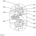
- the second gas bearing assembly 160 may comprise a second bearing seat 161 and a second radial bearing 162, wherein the second bearing seat 161 is fixed between the motor cavity 121 and the second impeller assembly 140, and the second radial bearing 162 is sleeved on the motor shaft 122 and located in the second bearing seat 161 (see FIG. 3 ).
- the second gas bearing assembly 160 further comprises a thrust plate 163, a first axial thrust bearing 164 and a second axial thrust bearing 165.
- the thrust plate 163 is fixed on the motor shaft 122 and is located between the second impeller assembly 140 and the second radial bearing 162.
- the first axial thrust bearing 164 is disposed next to one side of the thrust plate 163.
- the second axial thrust bearing 165 is disposed next to the other side of the thrust plate 163, wherein the first axial thrust bearing 164 and the second axial thrust bearing 165 are coaxially fixed in the second bearing seat 161 or the second impeller housing.
- the thrust plate 163 rotates at a high speed with the motor shaft, and forms a gas film with the foil structures of the first axial thrust bearing 164 and the second axial thrust bearing 165 on both sides, providing the effect of balancing the axial force. It should be noted that the position of the thrust plate can be adjusted flexibly. In addition to being disposed between the second impeller assembly 140 and the second radial bearing 162, the thrust plate can also be disposed between the motor cavity 121 and the second radial bearing 162.
- a thrust plate can also be provided on the side of the first gas bearing assembly.
- the first gas bearing assembly comprises: a thrust plate fixed on the motor shaft and located between the first impeller assembly and the first radial bearing or between the motor cavity and the first radial bearing; a first axial thrust bearing disposed next to one side of the thrust plate; and a second axial thrust bearing disposed next to the other side of the thrust plate, wherein the first axial thrust bearing and the second axial thrust bearing are coaxially fixed in the first bearing seat or the first impeller housing.
- a first wire mesh 170 is provided between the motor cavity 121 and the first gas bearing assembly 150.
- a second wire mesh 180 is provided between the motor cavity 121 and the second gas bearing assembly 160.
- a first baffle plate may also be provided on the side of the first bearing seat 151 close to the motor cavity 121. By blocking the gas inlet end of the first gas bearing assembly 150, the droplets from the motor cavity 121 can be effectively prevented from entering the first gas bearing assembly 150.
- a second baffle plate may also be provided on the side of the second bearing seat 161 close to the motor cavity 121. By blocking the gas inlet end of the second gas bearing assembly 160, the droplets from the motor cavity 121 can be effectively prevented from entering the second gas bearing assembly 160.
- the outlet pressure on the side of the gas bearing close to the motor cavity i.e., to make it greater than the pressure in the motor cavity.
- the outlet pressure on the side of the first gas bearing assembly close to the motor cavity is greater than the pressure in the motor cavity
- the outlet pressure on the side of the second gas bearing assembly close to the motor cavity is greater than the pressure in the motor cavity.
- the first labyrinth sealing mechanism 131 is provided on one or more of a fixed portion of the end of the first impeller of the first impeller assembly 130, the first impeller housing 132 and the first bearing seat 151; and the second labyrinth sealing mechanism 141 is provided on one or more of a fixed portion of the end of the second impeller of the second impeller assembly 140, the second impeller housing 142 and the second bearing seat 161.
- the first impeller housing 132 comprises suction chamber fasteners, volute fasteners, or other fasteners connected thereto.
- the second impeller housing 142 comprises suction chamber fasteners, volute fasteners, or other fasteners connected thereto.
- first radial bearing 152 of the first gas bearing assembly 150 and the second radial bearing 162 of the second gas bearing assembly 160 are configured to be of the same size, and are symmetrically disposed on both sides of the motor shaft 122 with respect to the motor cavity 121.
- first wire mesh 170 and the second wire mesh 180 can also be configured to be of the same size, and be symmetrically disposed on both sides of the motor shaft 122 with respect to the motor cavity 121.
- the centrifugal compressor according to the present invention by adopting the design of combining labyrinth seal of the impeller assembly with gas bearing, advantageously meets the gas supply requirements of the gas bearing by supplying the gas leakage generated by the labyrinth seal to the gas bearing, without adding additional gas supply pipes and drilling holes in other existing components.
- the present invention further provides a refrigerating system configured with the aforementioned centrifugal compressor.
- the refrigerating system may comprise a cooling tower, a water chiller, a pumping device, and the like that are connected by pipelines, wherein the water chiller is composed of components such as centrifugal compressor, condenser, throttling device and evaporator.
- the aforementioned centrifugal compressor can effectively achieve the purpose of supplying gas to the gas bearing without additional manufacturing cost, so it is highly recommended to apply the aforementioned centrifugal compressor to various refrigeration systems.
Landscapes
- Engineering & Computer Science (AREA)
- Mechanical Engineering (AREA)
- General Engineering & Computer Science (AREA)
- Physics & Mathematics (AREA)
- Fluid Mechanics (AREA)
- Thermal Sciences (AREA)
- Structures Of Non-Positive Displacement Pumps (AREA)
Abstract
Description
- The present invention relates to the technical field of refrigeration, in particular to a centrifugal compressor, and also relates to a refrigeration system configured with the centrifugal compressor.
- At present, centrifugal compressors gradually adopt oil-free lubrication technology to replace the original oil circuit lubrication, thereby eliminating the management of the lubricating oil system, such as oil circuit maintenance, oil return management and oil circuit system maintenance. On the other hand, oil-free lubrication also represents higher operation efficiency of the compressor and higher operation efficiency of the refrigeration system, lower vibration and noise, stable operation, greatly reduced cost, high cleanliness, and better user experience.
- A gas bearing is an important method and means for the solution of oil-free lubrication of centrifugal compressors. A centrifugal compressor supported by gas bearings is composed of a housing, a volute, impellers, gas bearings, a high-speed motor and other components. During the working process, the high-speed motor is supported by gas bearings at the left and right ends, with low rotational resistance and relatively high rotational speed. In order to supply gas to the gas bearings on both sides of the high-speed motor, it is usually necessary to add a gas supply system into the centrifugal compressor, such as adding additional gas supply pipes, or drilling holes in the components of the centrifugal compressor to create gas supply channels. Such gas supply method, however, increases the manufacturing difficulty and cost of centrifugal compressors.
- Therefore, there is an urgent need for a centrifugal compressor, which can solve the gas supply problem of the gas bearings without adding an additional gas supply system.
- In view of the above, according to a first aspect of the present invention, a centrifugal compressor is provided, which effectively solves the aforementioned problems and problems in other aspects existing in the prior art. In the centrifugal compressor according to the present invention, the centrifugal compressor comprises: a housing; a motor assembly disposed in the housing and comprising a motor cavity and a motor shaft located in the motor cavity, the motor shaft having a first end and a second end extending from the motor cavity; a first impeller assembly located at the first end of the motor shaft and provided with a first labyrinth sealing mechanism for reducing gas leakage from one side of the first impeller assembly close to the motor cavity; a second impeller assembly located at the second end of the motor shaft and provided with a second labyrinth sealing mechanism for reducing gas leakage from one side of the second impeller assembly close to the motor cavity; a first gas bearing assembly provided between the motor cavity and the first impeller assembly; and second gas bearing assembly provided between the motor cavity and the second impeller assembly; wherein the first labyrinth sealing mechanism is kept in gas communication with the first gas bearing assembly, such that the gas leaking from the side of the first impeller assembly close to the motor cavity is capable of being supplied to the first gas bearing assembly, and the second labyrinth sealing mechanism is kept in gas communication with the second gas bearing assembly, such that the gas leaking from the side of the second impeller assembly close to the motor cavity is capable of being supplied to the second gas bearing assembly.
- The first gas bearing assembly may comprise: a first bearing seat fixed between the motor cavity and the first impeller assembly; and a first radial bearing sleeved on the motor shaft and located in the first bearing seat; and the second gas bearing assembly may comprise: a second bearing seat fixed between the motor cavity and the second impeller assembly; and a second radial bearing sleeved on the motor shaft and located in the second bearing seat.
- The second gas bearing assembly may further comprise: a thrust plate fixed on the motor shaft and located between the second impeller assembly and the second radial bearing or between the motor cavity and the second radial bearing; a first axial thrust bearing disposed next to one side of the thrust plate; and a second axial thrust bearing disposed next to the other side of the thrust plate, wherein the first axial thrust bearing and the second axial thrust bearing may be coaxially fixed in the second bearing seat or a second impeller housing.
- The first gas bearing assembly may further comprise: a thrust plate fixed on the motor shaft and located between the first impeller assembly and the first radial bearing or between the motor cavity and the first radial bearing; a first axial thrust bearing disposed next to one side of the thrust plate; and a second axial thrust bearing disposed next to the other side of the thrust plate, wherein the first axial thrust bearing and the second axial thrust bearing may be coaxially fixed in the first bearing seat or a first impeller housing.
- A first wire mesh may be provided between the motor cavity and the first gas bearing assembly for preventing droplets from the motor cavity from entering the first gas bearing assembly, and a second wire mesh may be provided between the motor cavity and the second gas bearing assembly for preventing droplets from the motor cavity from entering the second gas bearing assembly.
- A first baffle plate may be provided on one side of the first bearing seat close to the motor cavity for preventing droplets from the motor cavity from entering the first gas bearing assembly, and a second baffle plate may be provided on one side of the second bearing seat close to the motor cavity for preventing droplets from the motor cavity from entering the second gas bearing assembly.
- The outlet pressure which may be on one side of the first gas bearing assembly close to the motor cavity may be greater than the pressure in the motor cavity, and the outlet pressure which may be on one side of the second gas bearing assembly close to the motor cavity may be greater than the pressure in the motor cavity.
- The first labyrinth sealing mechanism may be provided on one or more of a fixed portion of the end of the first impeller of the first impeller assembly, the first impeller housing and the first bearing seat; and the second labyrinth sealing mechanism may be provided on one or more of a fixed portion of the end of the second impeller of the second impeller assembly, the second impeller housing and the second bearing seat.
- The first radial bearing of the first gas bearing assembly and the second radial bearing of the second gas bearing assembly may be configured to be of the same size, and may be symmetrically disposed on both sides of the motor shaft with respect to the motor cavity.
- The first wire mesh and the second wire mesh may be configured to be of the same size, and may be symmetrically disposed on both sides of the motor shaft with respect to the motor cavity.
- A refrigeration system comprising the aforementioned centrifugal compressor may be further provided.
- It can be appreciated that the centrifugal compressor according to the present invention, by adopting the design of combining labyrinth seal of the impeller assembly with gas bearing assembly, may meet the gas supply requirements of the gas bearing assembly in a simple and economical manner without adding an additional gas supply system.
- The technical solutions of the present invention will be described in further detail below in conjunction with the accompanying drawings and embodiments, wherein:
-
FIG. 1 shows a cross-sectional schematic view of a centrifugal compressor; -
FIG. 2 shows a partially enlarged cross-sectional schematic view of the low-pressure stage comprising the first labyrinth sealing mechanism and the first gas bearing assembly of the centrifugal compressor according toFIG. 1 ; and -
FIG. 3 shows a partially enlarged cross-sectional schematic view of the high-pressure stage comprising the second labyrinth sealing mechanism and the second gas bearing assembly of the centrifugal compressor according toFIG. 1 . - Some embodiments of the present invention will be described in detail below with reference to the accompanying drawings. It should be noted that orientation terms such as upper, lower, left, right, front, rear, inner side, outer side, top and bottom mentioned or possibly mentioned in this specification are defined relative to the configurations illustrated in the respective drawings. They are relative concepts, so they may change accordingly according to their different locations and different states of use. Therefore, these and other orientation terms shall not be construed as restrictive terms.
- As shown in
FIG. 1 , it schematically illustrates the structure of an embodiment of the centrifugal compressor according to the present invention in general. As can be seen fromFIG. 1 , thecentrifugal compressor 100 is composed of ahousing 110, amotor assembly 120, afirst impeller assembly 130, asecond impeller assembly 140, a firstgas bearing assembly 150, a secondgas bearing assembly 160 and other components. Themotor assembly 120 is disposed in thehousing 110, and comprises amotor cavity 121 and amotor shaft 122, wherein themotor shaft 122 is located in themotor cavity 121 and has a first end and a second end extending from themotor cavity 121. Referring also toFIGS. 2 to 3 , thecentrifugal compressor 100 comprises a first stage or a second stage of two-stage compression in a back-to-back design: a low-pressure stage compression composed of thefirst impeller assembly 130, and a high-pressure stage compression composed of thesecond impeller assembly 140, wherein thesecond impeller assembly 140, i.e., the impeller of the second stage, is generally smaller than thefirst impeller assembly 130, i.e., the impeller of the first stage, wherein the inlet of the impeller of the second stage is the outlet of the impeller of the first stage. It can be appreciated that the centrifugal compressor may also comprise a first stage or a second stage disposed in parallel in a back-to-back design, wherein the impellers of the two stages are of the same size, that is, the inlet and outlet arrangements are the same. Thefirst impeller assembly 130 is located at the first end of themotor shaft 122, and is provided with a firstlabyrinth sealing mechanism 131, so as to reduce the gas leakage from the side of thefirst impeller assembly 130 close to themotor cavity 121, thereby limiting the gas leaking from the side of thefirst impeller assembly 130 close to themotor cavity 121 within a certain range. Thesecond impeller assembly 140 is located at the second end of themotor shaft 122, and is provided with a secondlabyrinth sealing mechanism 141, so as to reduce the gas leakage from the side of thesecond impeller assembly 140 close to themotor cavity 121, thereby limiting the gas leaking from the side of thesecond impeller assembly 140 close to themotor cavity 121 within a certain range. The firstgas bearing assembly 150 is disposed between themotor cavity 121 and thefirst impeller assembly 130, and the secondgas bearing assembly 160 is disposed between themotor cavity 121 and thesecond impeller assembly 140. - It should be noted that the first
labyrinth sealing mechanism 131 is kept in gas communication with the firstgas bearing assembly 150, so that the gas leaking from the side of thefirst impeller assembly 130 close to themotor cavity 121 can be supplied to the firstgas bearing assembly 150 to ensure that the firstgas bearing assembly 150 obtains adequate gas supply, lubrication and cooling. And, the secondlabyrinth sealing mechanism 141 is kept in gas communication with the secondgas bearing assembly 160, so that the gas leaking from the side of thesecond impeller assembly 140 close to themotor cavity 121 can be supplied to the secondgas bearing assembly 160 to ensure that the secondgas bearing assembly 160 obtains adequate gas supply, lubrication and cooling. The present invention adopts the design of combining the labyrinth seal of the compressor impeller assembly with the gas bearing assembly, providing the gas leakage of the labyrinth seal to the gas bearing assembly, so there is no need to add additional elbows or drill holes in other components to create gas supply channels. The centrifugal compressor according to the present invention can meet the gas supply requirements of the gas bearing assembly in a simple and economical manner. - In an embodiment of the centrifugal compressor according to the present invention, the first
gas bearing assembly 150 may comprise a first bearingseat 151 and a firstradial bearing 152, wherein the first bearingseat 151 is fixed between themotor cavity 121 and thefirst impeller assembly 130, and the firstradial bearing 152 is sleeved on themotor shaft 122 and located in the first bearing seat 151 (seeFIG. 2 ). The secondgas bearing assembly 160 may comprise asecond bearing seat 161 and a secondradial bearing 162, wherein thesecond bearing seat 161 is fixed between themotor cavity 121 and thesecond impeller assembly 140, and the secondradial bearing 162 is sleeved on themotor shaft 122 and located in the second bearing seat 161 (seeFIG. 3 ). - In order to counteract the axial force caused by the axial movement, the second
gas bearing assembly 160 further comprises athrust plate 163, a first axial thrust bearing 164 and a second axial thrust bearing 165. Thethrust plate 163 is fixed on themotor shaft 122 and is located between thesecond impeller assembly 140 and the second radial bearing 162. The first axial thrust bearing 164 is disposed next to one side of thethrust plate 163. The second axial thrust bearing 165 is disposed next to the other side of thethrust plate 163, wherein the first axial thrust bearing 164 and the second axial thrust bearing 165 are coaxially fixed in the second bearingseat 161 or the second impeller housing. When the motor is working, thethrust plate 163 rotates at a high speed with the motor shaft, and forms a gas film with the foil structures of the first axial thrust bearing 164 and the second axial thrust bearing 165 on both sides, providing the effect of balancing the axial force. It should be noted that the position of the thrust plate can be adjusted flexibly. In addition to being disposed between thesecond impeller assembly 140 and the secondradial bearing 162, the thrust plate can also be disposed between themotor cavity 121 and the secondradial bearing 162. - As an alternative, a thrust plate can also be provided on the side of the first gas bearing assembly. For example, the first gas bearing assembly comprises: a thrust plate fixed on the motor shaft and located between the first impeller assembly and the first radial bearing or between the motor cavity and the first radial bearing; a first axial thrust bearing disposed next to one side of the thrust plate; and a second axial thrust bearing disposed next to the other side of the thrust plate, wherein the first axial thrust bearing and the second axial thrust bearing are coaxially fixed in the first bearing seat or the first impeller housing.
- Those skilled in the art can appreciate that, during operation of the
centrifugal compressor 100, in order to cool the motor, holes are usually drilled in the housing of the motor to introduce a certain amount of refrigerant. Flash evaporation occurs through these holes to cool the motor, and the internal pressure of themotor cavity 121 is relatively low. In order to prevent droplets splashed from themotor cavity 121 from entering the firstgas bearing assembly 150, afirst wire mesh 170 is provided between themotor cavity 121 and the firstgas bearing assembly 150. Meanwhile, in order to prevent droplets splashed from themotor cavity 121 from entering the secondgas bearing assembly 160, asecond wire mesh 180 is provided between themotor cavity 121 and the secondgas bearing assembly 160. As an alternative, a first baffle plate may also be provided on the side of the first bearingseat 151 close to themotor cavity 121. By blocking the gas inlet end of the firstgas bearing assembly 150, the droplets from themotor cavity 121 can be effectively prevented from entering the firstgas bearing assembly 150. Similarly, a second baffle plate may also be provided on the side of the second bearingseat 161 close to themotor cavity 121. By blocking the gas inlet end of the secondgas bearing assembly 160, the droplets from themotor cavity 121 can be effectively prevented from entering the secondgas bearing assembly 160. In addition, it is also possible to prevent the droplets in the motor cavity from being sucked into the gas bearing by controlling and designing the outlet pressure on the side of the gas bearing close to the motor cavity, i.e., to make it greater than the pressure in the motor cavity. Specifically, the outlet pressure on the side of the first gas bearing assembly close to the motor cavity is greater than the pressure in the motor cavity, and the outlet pressure on the side of the second gas bearing assembly close to the motor cavity is greater than the pressure in the motor cavity. - In the embodiment shown in
FIGS. 2 to 3 , the firstlabyrinth sealing mechanism 131 is provided on one or more of a fixed portion of the end of the first impeller of thefirst impeller assembly 130, thefirst impeller housing 132 and the first bearingseat 151; and the secondlabyrinth sealing mechanism 141 is provided on one or more of a fixed portion of the end of the second impeller of thesecond impeller assembly 140, thesecond impeller housing 142 and thesecond bearing seat 161. Thefirst impeller housing 132 comprises suction chamber fasteners, volute fasteners, or other fasteners connected thereto. Similarly, thesecond impeller housing 142 comprises suction chamber fasteners, volute fasteners, or other fasteners connected thereto. - To facilitate manufacture, the first
radial bearing 152 of the firstgas bearing assembly 150 and the secondradial bearing 162 of the secondgas bearing assembly 160 are configured to be of the same size, and are symmetrically disposed on both sides of themotor shaft 122 with respect to themotor cavity 121. Of course, it is also feasible to configure the two to be of different sizes. Similarly, thefirst wire mesh 170 and thesecond wire mesh 180 can also be configured to be of the same size, and be symmetrically disposed on both sides of themotor shaft 122 with respect to themotor cavity 121. - To sum up, the centrifugal compressor according to the present invention, by adopting the design of combining labyrinth seal of the impeller assembly with gas bearing, advantageously meets the gas supply requirements of the gas bearing by supplying the gas leakage generated by the labyrinth seal to the gas bearing, without adding additional gas supply pipes and drilling holes in other existing components.
- In addition, the present invention further provides a refrigerating system configured with the aforementioned centrifugal compressor. The refrigerating system may comprise a cooling tower, a water chiller, a pumping device, and the like that are connected by pipelines, wherein the water chiller is composed of components such as centrifugal compressor, condenser, throttling device and evaporator. As mentioned above, the aforementioned centrifugal compressor can effectively achieve the purpose of supplying gas to the gas bearing without additional manufacturing cost, so it is highly recommended to apply the aforementioned centrifugal compressor to various refrigeration systems.
- Some specific embodiments are listed above to illustrate in detail a centrifugal compressor and a refrigeration system configured with the centrifugal compressor according to the present invention. These individual examples are only used to illustrate the principle of the present invention and the implementations thereof, but not to limit the present invention. Those skilled in the art may, without departing from the scope of the present invention as defined by the various claims of the present application.
Claims (11)
- A centrifugal compressor (100), comprising:a housing (110);a motor assembly (120) disposed in the housing (110) and comprising a motor cavity (121) and a motor shaft (122) located in the motor cavity (121), the motor shaft (122) having a first end and a second end extending from the motor cavity;a first impeller assembly (130) located at the first end of the motor shaft (122) and provided with a first labyrinth sealing mechanism (131) for reducing gas leakage from one side of the first impeller assembly (130) close to the motor cavity (122);a second impeller assembly (140) located at the second end of the motor shaft (122) and provided with a second labyrinth sealing mechanism (141) for reducing gas leakage from one side of the second impeller assembly (140) close to the motor cavity (122);a first gas bearing assembly (150) provided between the motor cavity (122) and the first impeller assembly (130); anda second gas bearing assembly (160) provided between the motor cavity (122) and the second impeller assembly (140);wherein the first labyrinth sealing mechanism (131) is kept in gas communication with the first gas bearing assembly (150), such that the gas leaking from the side of the first impeller assembly (130) close to the motor cavity (122) is capable of being supplied to the first gas bearing assembly (150), and the second labyrinth sealing mechanism (141) is kept in gas communication with the second gas bearing assembly (160), such that the gas leaking from the side of the second impeller assembly (140) close to the motor cavity (122) is capable of being supplied to the second gas bearing assembly (160).
- The centrifugal compressor according to claim 1, wherein:the first gas bearing assembly (150) comprises: a first bearing seat (151) fixed between the motor cavity (122) and the first impeller assembly (130); and a first radial bearing (152) sleeved on the motor shaft and located in the first bearing seat (151); andthe second gas bearing assembly (160) comprises: a second bearing seat (161) fixed between the motor cavity (122) and the second impeller assembly (140); and a second radial bearing (162) sleeved on the motor shaft and located in the second bearing seat (161).
- The centrifugal compressor according to claim 2, wherein the second gas bearing assembly (160) further comprises:a thrust plate (163) fixed on the motor shaft and located between the second impeller assembly (140) and the second radial bearing (162) or between the motor cavity (122) and the second radial bearing (162);a first axial thrust bearing (164) disposed next to one side of the thrust plate (163); anda second axial thrust (165) bearing disposed next to the other side of the thrust plate (163),wherein the first axial thrust bearing and the second axial thrust bearing are coaxially fixed in the second bearing seat (161) or a second impeller housing (142).
- The centrifugal compressor according to claim 2, wherein the first gas bearing assembly (160) further comprises:a thrust plate (163) fixed on the motor shaft and located between the first impeller assembly (130) and the first radial bearing (152) or between the motor cavity (122) and the first radial bearing;a first axial thrust bearing (164) disposed next to one side of the thrust plate; anda second axial thrust bearing (165) disposed next to the other side of the thrust plate,wherein the first axial thrust bearing (164) and the second axial thrust bearing (165) are coaxially fixed in the first bearing seat (161) or a first impeller housing (142).
- The centrifugal compressor according to any of claims 1 to 4, wherein a first wire mesh (170) is provided between the motor cavity (122) and the first gas bearing assembly for preventing droplets from the motor cavity from entering the first gas bearing assembly (150), and a second wire mesh (180) is provided between the motor cavity and the second gas bearing assembly (160) for preventing droplets from the motor cavity from entering the second gas bearing assembly.
- The centrifugal compressor according to any of claims 2 to 4, wherein a first baffle plate is provided on one side of the first bearing seat (161) close to the motor cavity for preventing droplets from the motor cavity (122) from entering the first gas bearing assembly (150), and a second baffle plate is provided on one side of the second bearing seat (161) close to the motor cavity (122) for preventing droplets from the motor cavity from entering the second gas bearing assembly (160).
- The centrifugal compressor according to any of claims 1 to 4, wherein outlet pressure on one side of the first gas bearing assembly (!50) close to the motor cavity is greater than pressure in the motor cavity (122), and outlet pressure on one side of the second gas bearing assembly (160) close to the motor cavity (122) is greater than pressure in the motor cavity.
- The centrifugal compressor according to any of claims 2 to 4, wherein the first labyrinth sealing mechanism (131) is provided on one or more of a fixed portion of the end of the first impeller of the first impeller assembly (130), the first impeller housing (132) and the first bearing seat (151); and the second labyrinth sealing mechanism (141) is provided on one or more of a fixed portion of the end of the second impeller of the second impeller assembly (140), the second impeller housing (142) and the second bearing seat (161).
- The centrifugal compressor according to any of claims 2 to 4, wherein the first radial bearing (152) of the first gas bearing assembly (150) and the second radial bearing (162) of the second gas bearing assembly (160) are configured to be of the same size, and are symmetrically disposed on both sides of the motor shaft with respect to the motor cavity.
- The centrifugal compressor according to claim 5, wherein the first wire mesh (170) and the second wire mesh (180) are configured to be of the same size, and are symmetrically disposed on both sides of the motor shaft (122) with respect to the motor cavity.
- A refrigeration system, wherein the refrigeration system comprises the centrifugal compressor (100) according to any of claims 1 to 10.
Applications Claiming Priority (1)
| Application Number | Priority Date | Filing Date | Title |
|---|---|---|---|
| CN202110677256.6A CN115492779A (en) | 2021-06-18 | 2021-06-18 | Centrifugal compressors and refrigeration systems |
Publications (1)
| Publication Number | Publication Date |
|---|---|
| EP4105492A1 true EP4105492A1 (en) | 2022-12-21 |
Family
ID=82020195
Family Applications (1)
| Application Number | Title | Priority Date | Filing Date |
|---|---|---|---|
| EP22178496.0A Pending EP4105492A1 (en) | 2021-06-18 | 2022-06-10 | Centrifugal compressor and refrigeration system |
Country Status (3)
| Country | Link |
|---|---|
| US (1) | US11965515B2 (en) |
| EP (1) | EP4105492A1 (en) |
| CN (1) | CN115492779A (en) |
Families Citing this family (4)
| Publication number | Priority date | Publication date | Assignee | Title |
|---|---|---|---|---|
| CN115891583B (en) * | 2022-12-28 | 2025-12-26 | 华涧新能源科技(上海)有限公司 | An automotive air conditioning system based on an air flotation centrifugal compressor |
| CN115912765B (en) * | 2022-12-30 | 2026-03-27 | 珠海格力电器股份有限公司 | An air flotation motor system |
| CN117514852B (en) * | 2023-10-20 | 2024-06-11 | 广东聚磁动力科技有限公司 | A magnetic levitation compressor and its control method, device and storage medium |
| US20250297614A1 (en) * | 2024-03-22 | 2025-09-25 | Garrett Transportation I Inc. | Static gas thrust bearing |
Citations (5)
| Publication number | Priority date | Publication date | Assignee | Title |
|---|---|---|---|---|
| US4385768A (en) * | 1979-07-19 | 1983-05-31 | Rotoflow Corporation, Inc. | Shaft mounting device and method |
| US20040179947A1 (en) * | 2002-12-19 | 2004-09-16 | R & D Dynamics Corporation | Motor driven two-stage centrifugal air-conditioning compressor |
| JP2009270797A (en) * | 2008-05-09 | 2009-11-19 | Daikin Ind Ltd | Refrigerating device |
| DE102012207019A1 (en) * | 2012-04-27 | 2013-10-31 | Siemens Aktiengesellschaft | Turbomachine and method for cooling such |
| US20200291953A1 (en) * | 2019-03-11 | 2020-09-17 | Emerson Climate Technologies, Inc. | Foil bearing assembly and compressor including same |
Family Cites Families (6)
| Publication number | Priority date | Publication date | Assignee | Title |
|---|---|---|---|---|
| US1427974A (en) * | 1920-12-06 | 1922-09-05 | Charles R Sessions | Pump |
| BE790969A (en) * | 1971-11-16 | 1973-05-07 | Cit Alcatel | PIVOT FOR ROTARY MOLECULAR PUMPS |
| GB201307674D0 (en) * | 2013-04-29 | 2013-06-12 | Cummins Ltd | Turbomachine With Axial Stop Member |
| CN205779765U (en) * | 2016-06-22 | 2016-12-07 | 上海瑚石制冷设备科技有限公司 | A kind of horizontal refrigerant pump |
| CN206943036U (en) * | 2017-05-05 | 2018-01-30 | 成都慧利环保科技有限公司 | The air suspension blower fan of high muting function |
| US11603884B2 (en) * | 2021-05-07 | 2023-03-14 | Trane International Inc. | Gas bearing with integral non-contacting seal |
-
2021
- 2021-06-18 CN CN202110677256.6A patent/CN115492779A/en active Pending
-
2022
- 2022-06-10 EP EP22178496.0A patent/EP4105492A1/en active Pending
- 2022-06-14 US US17/839,734 patent/US11965515B2/en active Active
Patent Citations (5)
| Publication number | Priority date | Publication date | Assignee | Title |
|---|---|---|---|---|
| US4385768A (en) * | 1979-07-19 | 1983-05-31 | Rotoflow Corporation, Inc. | Shaft mounting device and method |
| US20040179947A1 (en) * | 2002-12-19 | 2004-09-16 | R & D Dynamics Corporation | Motor driven two-stage centrifugal air-conditioning compressor |
| JP2009270797A (en) * | 2008-05-09 | 2009-11-19 | Daikin Ind Ltd | Refrigerating device |
| DE102012207019A1 (en) * | 2012-04-27 | 2013-10-31 | Siemens Aktiengesellschaft | Turbomachine and method for cooling such |
| US20200291953A1 (en) * | 2019-03-11 | 2020-09-17 | Emerson Climate Technologies, Inc. | Foil bearing assembly and compressor including same |
Also Published As
| Publication number | Publication date |
|---|---|
| CN115492779A (en) | 2022-12-20 |
| US20220403850A1 (en) | 2022-12-22 |
| US11965515B2 (en) | 2024-04-23 |
Similar Documents
| Publication | Publication Date | Title |
|---|---|---|
| EP4105492A1 (en) | Centrifugal compressor and refrigeration system | |
| EP2766676B1 (en) | Motor cooling and sub-cooling circuits for compressor | |
| EP3112691B1 (en) | Compressor and refrigerating cycle apparatus | |
| JP6056270B2 (en) | Turbo compressor and turbo refrigerator | |
| US9671146B2 (en) | Refrigerant cooling and lubrication system with refrigerant vapor vent line | |
| US8424339B2 (en) | Method and system for rotor cooling | |
| CN105051466A (en) | Compressor bearing cooling | |
| CN101504002B (en) | Turbo compressors and refrigerators | |
| WO2016136482A1 (en) | Oilless compressor | |
| US10227995B2 (en) | Turbo compressor and turbo refrigerating machine | |
| JP4981557B2 (en) | Turbo compressor and turbo refrigerator | |
| WO2024103959A1 (en) | Compressor and air conditioner | |
| JP2016166536A (en) | Rotating machine | |
| CN215762308U (en) | Compressor and refrigerator provided with same | |
| JP2016200058A (en) | Oil supply type displacement compressor | |
| JP2014190616A (en) | Compressor electric motor of turbo refrigerator | |
| JP2018123759A (en) | Turbocompressor | |
| CN204942021U (en) | Centrifugal compressor and there is its room air conditioner | |
| CN111486103B (en) | Centrifugal compressor and heat pump system | |
| US20160116190A1 (en) | Turbo refrigerator | |
| CN105114341A (en) | Centrifugal compressor and room air conditioner comprising same | |
| JP2000291587A (en) | Multi-stage compressor for refrigerator | |
| CN111486105B (en) | Centrifugal compressor and heat pump system | |
| JP2017106330A (en) | Turbo machine | |
| JP6044156B2 (en) | Oil drain structure, turbo compressor and turbo refrigerator |
Legal Events
| Date | Code | Title | Description |
|---|---|---|---|
| PUAI | Public reference made under article 153(3) epc to a published international application that has entered the european phase |
Free format text: ORIGINAL CODE: 0009012 |
|
| STAA | Information on the status of an ep patent application or granted ep patent |
Free format text: STATUS: THE APPLICATION HAS BEEN PUBLISHED |
|
| AK | Designated contracting states |
Kind code of ref document: A1 Designated state(s): AL AT BE BG CH CY CZ DE DK EE ES FI FR GB GR HR HU IE IS IT LI LT LU LV MC MK MT NL NO PL PT RO RS SE SI SK SM TR |
|
| STAA | Information on the status of an ep patent application or granted ep patent |
Free format text: STATUS: REQUEST FOR EXAMINATION WAS MADE |
|
| 17P | Request for examination filed |
Effective date: 20230620 |
|
| RBV | Designated contracting states (corrected) |
Designated state(s): AL AT BE BG CH CY CZ DE DK EE ES FI FR GB GR HR HU IE IS IT LI LT LU LV MC MK MT NL NO PL PT RO RS SE SI SK SM TR |
|
| STAA | Information on the status of an ep patent application or granted ep patent |
Free format text: STATUS: EXAMINATION IS IN PROGRESS |
|
| 17Q | First examination report despatched |
Effective date: 20240930 |
|
| GRAP | Despatch of communication of intention to grant a patent |
Free format text: ORIGINAL CODE: EPIDOSNIGR1 |
|
| STAA | Information on the status of an ep patent application or granted ep patent |
Free format text: STATUS: GRANT OF PATENT IS INTENDED |
|
| INTG | Intention to grant announced |
Effective date: 20260212 |