EP4105484A1 - Mobile operating machine and fuctioning method of said mobile operating machine - Google Patents
Mobile operating machine and fuctioning method of said mobile operating machine Download PDFInfo
- Publication number
- EP4105484A1 EP4105484A1 EP22179481.1A EP22179481A EP4105484A1 EP 4105484 A1 EP4105484 A1 EP 4105484A1 EP 22179481 A EP22179481 A EP 22179481A EP 4105484 A1 EP4105484 A1 EP 4105484A1
- Authority
- EP
- European Patent Office
- Prior art keywords
- operating machine
- mobile operating
- endothermic engine
- electric motor
- hydraulic pump
- Prior art date
- Legal status (The legal status is an assumption and is not a legal conclusion. Google has not performed a legal analysis and makes no representation as to the accuracy of the status listed.)
- Granted
Links
Images


Classifications
-
- E—FIXED CONSTRUCTIONS
- E04—BUILDING
- E04G—SCAFFOLDING; FORMS; SHUTTERING; BUILDING IMPLEMENTS OR AIDS, OR THEIR USE; HANDLING BUILDING MATERIALS ON THE SITE; REPAIRING, BREAKING-UP OR OTHER WORK ON EXISTING BUILDINGS
- E04G21/00—Preparing, conveying, or working-up building materials or building elements in situ; Other devices or measures for constructional work
- E04G21/02—Conveying or working-up concrete or similar masses able to be heaped or cast
- E04G21/04—Devices for both conveying and distributing
-
- F—MECHANICAL ENGINEERING; LIGHTING; HEATING; WEAPONS; BLASTING
- F04—POSITIVE - DISPLACEMENT MACHINES FOR LIQUIDS; PUMPS FOR LIQUIDS OR ELASTIC FLUIDS
- F04B—POSITIVE-DISPLACEMENT MACHINES FOR LIQUIDS; PUMPS
- F04B49/00—Control, e.g. of pump delivery, or pump pressure of, or safety measures for, machines, pumps, or pumping installations, not otherwise provided for, or of interest apart from, groups F04B1/00 - F04B47/00
- F04B49/06—Control using electricity
-
- B—PERFORMING OPERATIONS; TRANSPORTING
- B28—WORKING CEMENT, CLAY, OR STONE
- B28C—PREPARING CLAY; PRODUCING MIXTURES CONTAINING CLAY OR CEMENTITIOUS MATERIAL, e.g. PLASTER
- B28C5/00—Apparatus or methods for producing mixtures of cement with other substances, e.g. slurries, mortars, porous or fibrous compositions
- B28C5/42—Apparatus specially adapted for being mounted on vehicles with provision for mixing during transport
- B28C5/4203—Details; Accessories
- B28C5/4206—Control apparatus; Drive systems, e.g. coupled to the vehicle drive-system
- B28C5/421—Drives
- B28C5/4213—Hydraulic drives
-
- B—PERFORMING OPERATIONS; TRANSPORTING
- B28—WORKING CEMENT, CLAY, OR STONE
- B28C—PREPARING CLAY; PRODUCING MIXTURES CONTAINING CLAY OR CEMENTITIOUS MATERIAL, e.g. PLASTER
- B28C5/00—Apparatus or methods for producing mixtures of cement with other substances, e.g. slurries, mortars, porous or fibrous compositions
- B28C5/42—Apparatus specially adapted for being mounted on vehicles with provision for mixing during transport
- B28C5/4203—Details; Accessories
- B28C5/4234—Charge or discharge systems therefor
- B28C5/4244—Discharging; Concrete conveyor means, chutes or spouts therefor
- B28C5/4258—Discharging; Concrete conveyor means, chutes or spouts therefor using pumps or transporting screws
-
- B—PERFORMING OPERATIONS; TRANSPORTING
- B60—VEHICLES IN GENERAL
- B60K—ARRANGEMENT OR MOUNTING OF PROPULSION UNITS OR OF TRANSMISSIONS IN VEHICLES; ARRANGEMENT OR MOUNTING OF PLURAL DIVERSE PRIME-MOVERS IN VEHICLES; AUXILIARY DRIVES FOR VEHICLES; INSTRUMENTATION OR DASHBOARDS FOR VEHICLES; ARRANGEMENTS IN CONNECTION WITH COOLING, AIR INTAKE, GAS EXHAUST OR FUEL SUPPLY OF PROPULSION UNITS IN VEHICLES
- B60K25/00—Auxiliary drives
-
- B—PERFORMING OPERATIONS; TRANSPORTING
- B60—VEHICLES IN GENERAL
- B60K—ARRANGEMENT OR MOUNTING OF PROPULSION UNITS OR OF TRANSMISSIONS IN VEHICLES; ARRANGEMENT OR MOUNTING OF PLURAL DIVERSE PRIME-MOVERS IN VEHICLES; AUXILIARY DRIVES FOR VEHICLES; INSTRUMENTATION OR DASHBOARDS FOR VEHICLES; ARRANGEMENTS IN CONNECTION WITH COOLING, AIR INTAKE, GAS EXHAUST OR FUEL SUPPLY OF PROPULSION UNITS IN VEHICLES
- B60K25/00—Auxiliary drives
- B60K25/02—Auxiliary drives directly from an engine shaft
-
- E—FIXED CONSTRUCTIONS
- E04—BUILDING
- E04G—SCAFFOLDING; FORMS; SHUTTERING; BUILDING IMPLEMENTS OR AIDS, OR THEIR USE; HANDLING BUILDING MATERIALS ON THE SITE; REPAIRING, BREAKING-UP OR OTHER WORK ON EXISTING BUILDINGS
- E04G21/00—Preparing, conveying, or working-up building materials or building elements in situ; Other devices or measures for constructional work
- E04G21/02—Conveying or working-up concrete or similar masses able to be heaped or cast
- E04G21/04—Devices for both conveying and distributing
- E04G21/0418—Devices for both conveying and distributing with distribution hose
- E04G21/0436—Devices for both conveying and distributing with distribution hose on a mobile support, e.g. truck
-
- E—FIXED CONSTRUCTIONS
- E04—BUILDING
- E04G—SCAFFOLDING; FORMS; SHUTTERING; BUILDING IMPLEMENTS OR AIDS, OR THEIR USE; HANDLING BUILDING MATERIALS ON THE SITE; REPAIRING, BREAKING-UP OR OTHER WORK ON EXISTING BUILDINGS
- E04G21/00—Preparing, conveying, or working-up building materials or building elements in situ; Other devices or measures for constructional work
- E04G21/02—Conveying or working-up concrete or similar masses able to be heaped or cast
- E04G21/04—Devices for both conveying and distributing
- E04G21/0418—Devices for both conveying and distributing with distribution hose
- E04G21/0445—Devices for both conveying and distributing with distribution hose with booms
-
- F—MECHANICAL ENGINEERING; LIGHTING; HEATING; WEAPONS; BLASTING
- F04—POSITIVE - DISPLACEMENT MACHINES FOR LIQUIDS; PUMPS FOR LIQUIDS OR ELASTIC FLUIDS
- F04B—POSITIVE-DISPLACEMENT MACHINES FOR LIQUIDS; PUMPS
- F04B35/00—Piston pumps specially adapted for elastic fluids and characterised by the driving means to their working members, or by combination with, or adaptation to, specific driving engines or motors, not otherwise provided for
- F04B35/002—Piston pumps specially adapted for elastic fluids and characterised by the driving means to their working members, or by combination with, or adaptation to, specific driving engines or motors, not otherwise provided for driven by internal combustion engines
-
- B—PERFORMING OPERATIONS; TRANSPORTING
- B60—VEHICLES IN GENERAL
- B60K—ARRANGEMENT OR MOUNTING OF PROPULSION UNITS OR OF TRANSMISSIONS IN VEHICLES; ARRANGEMENT OR MOUNTING OF PLURAL DIVERSE PRIME-MOVERS IN VEHICLES; AUXILIARY DRIVES FOR VEHICLES; INSTRUMENTATION OR DASHBOARDS FOR VEHICLES; ARRANGEMENTS IN CONNECTION WITH COOLING, AIR INTAKE, GAS EXHAUST OR FUEL SUPPLY OF PROPULSION UNITS IN VEHICLES
- B60K25/00—Auxiliary drives
- B60K25/02—Auxiliary drives directly from an engine shaft
- B60K2025/026—Auxiliary drives directly from an engine shaft by a hydraulic transmission
Definitions
- the present invention concerns a mobile operating machine and its functioning method.
- the mobile operating machine to which the present invention refers is preferably a truck-mounted pump for the delivery and distribution of concrete.
- Truck-mounted pumps normally comprise an articulated arm that can be extended to several segments, a pumping unit which has the function of pumping the concrete toward the delivery zone, and a stabilizing unit, provided with one or more extendable support feet, which has the function of stabilizing the entire vehicle during the pumping and delivery of the concrete.
- the articulated arm is associated with a pipe that extends for its entire length, and through this pipe the concrete is pumped to be delivered to the desired zone by the operator.
- the last portion of the pipe is the one that is handled by the operator to perform the delivery and targeted distribution of the concrete.
- Each segment, or section, of the articulated arm is associated with at least its own actuator, or hydraulic motor, which allows the rotation and movement of one section with respect to the other.
- the drive of the concrete pumping unit, and possibly of the actuators associated with the arm is commanded by an endothermic engine, for example a diesel engine, which is the same one that drives the vehicle engine of the mobile operating machine.
- an endothermic engine for example a diesel engine, which is the same one that drives the vehicle engine of the mobile operating machine.
- one disadvantage of known mobile operating machines is that, for the entire duration of the distribution of the concrete, the endothermic engine must remain switched on, causing prolonged emissions of exhaust gases that are harmful to both health and the environment.
- Solutions of operating machines are known, for example concrete mixers, which use hybrid-type engine solutions, in which, for example, the drive of the concrete mixing drum is entrusted at least partly to an electric motor.
- Document DE102018214965A1 generically describes a truck-mounted hybrid pump where a liquid-cooled asynchronous motor is installed, that is, an electric motor characterized by specific functions, which can be connected to an endothermic engine and/or to an electric accumulator.
- the connection between the endothermic engine and the electric motor takes place by means of a transmission shaft.
- the electric motor and the accumulator can be connected to an external electric network for recharging and power.
- the electric functioning of the truck-mounted pump is not described in detail.
- Document US9.850.671B2 describes an electric operating machine used specifically for working in tunnels, having a generator to power the various functions of the operating machine, in particular for the front and/or rear traction of the same machine.
- the generator can be powered either by an external electric network or by an endothermic engine.
- the endothermic engine is mainly used for moving the operating machine.
- One purpose of the present invention is to provide a mobile operating machine, in particular a truck-mounted pump, which is efficient and versatile for the different modes of use for which the machine is intended, and in particular reduces polluting emissions and noise emissions when it is functioning.
- a derived purpose is therefore to be able to use the operating machine even in city centers, or in particular sensitive areas and in any time band, without problems of noise and environmental pollution.
- Another purpose of the present invention is to provide a mobile operating machine in which the drive of at least some of the operating components of the operating machine takes place without the aid of the endothermic engine.
- one purpose of the present invention is to provide a mobile operating machine in which the articulated arm, or the stabilizing system, can be driven even when the endothermic engine is switched off, for example when the vehicle is stationary.
- the Applicant has devised, tested and embodied the present invention to overcome the shortcomings of the state of the art and to obtain these and other purposes and advantages.
- a mobile operating machine comprises a motor vehicle moved by an endothermic engine, an articulated arm associated with a concrete delivery pipe, a pumping unit suitable to pump concrete into the pipe and a stabilizing unit for stabilizing the operating machine at least during the pumping and delivery of the concrete.
- the endothermic engine is provided with at least a first power take-off and a second power take-off distinct from the first power take-off, which can be selectively activated with respect to each other.
- At least one hydraulic pump which drives the articulated arm and the stabilizing unit, and an electric motor and accumulator are connected to the first power take-off, by means of a first drive axis, and at least the pumping unit is connected to the second power take-off by means of a second drive axis, distinct from the first drive axis.
- a disengagement device which can be selectively activated to alternatively determine the drive of the hydraulic pump by means of the endothermic engine or by means of the electric motor.
- the truck-mounted pump according to the present invention can be used, for the operating part relating to the movement of the stabilizers and the articulated arm, exclusively by driving the electric motor, therefore in a silent and non-polluting way, while only the part relating to the pumping of concrete is entrusted to the drive of the endothermic engine.
- a mobile operating machine which in this case is a truck-mounted pump 10, is used for the distribution and delivery of concrete in operating sites, for example a construction site.
- the mobile operating machine 10 schematically comprises a conventional motor vehicle 11, represented in its entirety by a broken line, moved by an endothermic engine 12, such as a conventional diesel engine.
- an articulated arm 13 mounted on the motor vehicle 11 there is an articulated arm 13 associated with an extendable pipe 32 for delivering concrete, a pumping unit 15, and a stabilizing unit 16 which has the function of stabilizing the motor vehicle 11 once it has reached the operating site.
- the endothermic engine 12 is provided with a drive shaft 17 which allows to rotate a transmission shaft 19 of a movement unit 20, which is provided with wheels 21.
- a clutch 22 and a gearbox 23 of any known type can be associated with the drive shaft 17, to determine the drive of the movement unit 20.
- the endothermic engine 12 is connected to at least a first power take-off 25 and a second power take-off 26 which are distinct from each other and can be activated selectively with respect to each other.
- the mobile operating machine 10 also comprises a drive apparatus 27, indicated in its entirety by a broken line, operatively connected to the power take-offs 25, 26 of the endothermic engine 12 and configured to drive the articulated arm 13, the pumping unit 15, the stabilizing unit 16, as well as other electric or hydraulic service units 28 of the operating machine 10.
- a drive apparatus 27 indicated in its entirety by a broken line, operatively connected to the power take-offs 25, 26 of the endothermic engine 12 and configured to drive the articulated arm 13, the pumping unit 15, the stabilizing unit 16, as well as other electric or hydraulic service units 28 of the operating machine 10.
- the drive apparatus 27 has a first drive axis, indicated by A1, associated with the first power take-off 25 and a second drive axis, indicated by A2, associated with the second power take-off 26.
- a hydraulic pump 29 is positioned along the first drive axis A1, operatively connected to the first power take-off 25 and configured to pump a work fluid to determine the selectively alternating drive of the articulated arm 13 and the stabilizing unit 16.
- the articulated arm 13 comprises a plurality of sections 30 reciprocally articulated and moved by respective hydraulic actuators 31, or motors, and the pipe 32, associated with the sections 30, through which the concrete is pumped toward the delivery zone.
- the actuators 31 are operatively connected to the hydraulic pump 29 which drives them by supplying them with the work fluid so that the articulated arm 13 can assume the desired position.
- the stabilizing unit 16 comprises one or more support devices 33, for example extendable support feet, preferably distributed symmetrically on the perimeter of the operating machine 10.
- the support devices 33 are also operatively connected to the hydraulic pump 29 which drives them, supplying them with the work fluid so that they can be moved to stabilize and secure the operating machine 10 before and during pumping and delivery of the concrete.
- the drive apparatus 27 also comprises, disposed along the first drive axis A1 and operatively connected to each other, an electric motor 35, provided with a converter 36 which acts as an inverter, and connected in turn to the hydraulic pump 29, and an electric accumulator 37.
- the hydraulic pump 29 is the type which also allows the connection, and therefore the transmission of mechanical energy, from the endothermic engine 12 to the electric motor 35.
- the electric motor 35 can assume at least a first operating condition in which it converts the electrical energy of the electric accumulator 37 into mechanical energy to drive the hydraulic pump 29, and a second operating condition in which it converts the mechanical energy of the endothermic engine 12 into electrical energy to recharge the electric accumulator 37. Therefore, the electric motor 35 can function both as a motor and as a generator.
- the converter 36 is responsible for the control of the electric motor 35, that is, the management of continuous and/or alternating electrical energy, and is operatively connected to the electric accumulator 37.
- the electric accumulator 37 comprises, for example, one or more electric batteries and can be provided with a connection device 39 configured to connect the electric accumulator 37 to an electrical energy source, for example a normal electric network, when the energy level of the electric accumulator 37 is low.
- an electrical energy source for example a normal electric network
- a disengagement device 40 is positioned, for example an overrun joint or free wheel, configured to selectively disconnect the first power take-off 25 of the endothermic engine 12 from the hydraulic pump 29 and from the electric motor 35.
- the disengagement device 40 when it is connected, allows the transmission of the mechanical energy of the endothermic engine 12 to the hydraulic pump 29 and, possibly, to the electric motor 35, which in this case acts as a generator to recharge the accumulator 37, for example in the case of a KERS-type energy recovery system; on the contrary, when it is disconnected, it prevents the transmission of the mechanical energy generated by the electric motor 35 toward the endothermic engine 12.
- the articulated arm 13 and the stabilizing unit 16 can function in hybrid mode, that is, alternatively, either by means of the endothermic engine 12 or by means of the electric motor 35.
- the preferential drive will take place through the electric motor 35 and, at least in the event that the energy level in the accumulator 37 falls below a certain threshold, the drive will be switched by means of the endothermic engine 12.
- the pumping unit 15 that is, the unit suitable to pump concrete through the pipe 32 associated with the articulated arm 13, and other electric or hydraulic service units 28.
- the mobile operating machine 10 also comprises a central control unit 41 which is operatively connected at least to the endothermic engine 12, to the electric motor 35 and to the electric accumulator 37.
- the central control unit 41 is programmed to automatically manage both the hybrid mode of the articulated arm 13 and the stabilizing unit 16, and also the start and stop of the endothermic engine 12, when the pumping unit 15 is activated and, respectively, deactivated, possibly to activate, for example, the stabilizing unit 16.
- the central control unit 41 is set so as to preferentially start the electric motor 35 to drive the hydraulic pump 29, the stabilizing unit 16 to secure the operating machine 10 and therefore the articulated arm 13.
- the endothermic engine 12 can be started automatically in order to drive the articulated arm 13 or the stabilizing unit 16 only when the level of energy accumulated in the electric accumulator 37 is, or falls below a minimum energy threshold.
- the functioning of the mobile operating machine 10 described heretofore, which corresponds to the method according to the present invention, comprises at least four functioning modes F1, F2, F3, F4.
- a first functioning mode F1 of the mobile operating machine 10 according to the present invention is shown in fig. 2 and comprises the following steps:
- a second functioning mode F2 of the mobile operating machine 10 according to the present invention is shown in fig. 3 and comprises, in addition to the steps of the first functioning mode F1, the following step:
- a third functioning mode F3 of the mobile operating machine 10 according to the present invention is shown in fig. 4 and comprises the following steps:
- a fourth functioning mode F4 of the mobile operating machine 10 according to the present invention is shown schematically in fig. 5 and comprises the following steps:
- the electric accumulator 37 can be connected, by means of the connection device 39, to a source of electrical energy, for example to the electricity network, to be recharged.
- the positioning of the disengagement device 40 along the first drive axis A1 has the advantage of allowing the management of the torque entering and/or leaving the first drive axis A1 without generating imbalances in the endothermic engine 12 of the motor vehicle 11, that is, without altering the behavior of the endothermic engine 12.
Landscapes
- Engineering & Computer Science (AREA)
- Mechanical Engineering (AREA)
- Architecture (AREA)
- Structural Engineering (AREA)
- Civil Engineering (AREA)
- Chemical & Material Sciences (AREA)
- Combustion & Propulsion (AREA)
- Transportation (AREA)
- General Engineering & Computer Science (AREA)
- Auxiliary Drives, Propulsion Controls, And Safety Devices (AREA)
- Operation Control Of Excavators (AREA)
- Electrical Discharge Machining, Electrochemical Machining, And Combined Machining (AREA)
- Lifting Devices For Agricultural Implements (AREA)
Abstract
Description
- The present invention concerns a mobile operating machine and its functioning method.
- In particular, the mobile operating machine to which the present invention refers is preferably a truck-mounted pump for the delivery and distribution of concrete.
- In the field of civil construction, the use is known of mobile operating machines, such as truck-mounted pumps, or suchlike, that is, pumps with a corresponding arm to deliver concrete that are mounted on a transport vehicle.
- Truck-mounted pumps normally comprise an articulated arm that can be extended to several segments, a pumping unit which has the function of pumping the concrete toward the delivery zone, and a stabilizing unit, provided with one or more extendable support feet, which has the function of stabilizing the entire vehicle during the pumping and delivery of the concrete.
- The articulated arm is associated with a pipe that extends for its entire length, and through this pipe the concrete is pumped to be delivered to the desired zone by the operator.
- The last portion of the pipe is the one that is handled by the operator to perform the delivery and targeted distribution of the concrete.
- Each segment, or section, of the articulated arm is associated with at least its own actuator, or hydraulic motor, which allows the rotation and movement of one section with respect to the other.
- In the current state of the art, the drive of the concrete pumping unit, and possibly of the actuators associated with the arm, is commanded by an endothermic engine, for example a diesel engine, which is the same one that drives the vehicle engine of the mobile operating machine.
- Therefore, one disadvantage of known mobile operating machines is that, for the entire duration of the distribution of the concrete, the endothermic engine must remain switched on, causing prolonged emissions of exhaust gases that are harmful to both health and the environment.
- Furthermore, known mobile operating machines are often noisy, and therefore also have problems of noise pollution.
- Solutions of operating machines are known, for example concrete mixers, which use hybrid-type engine solutions, in which, for example, the drive of the concrete mixing drum is entrusted at least partly to an electric motor.
- Document
DE102018214965A1 generically describes a truck-mounted hybrid pump where a liquid-cooled asynchronous motor is installed, that is, an electric motor characterized by specific functions, which can be connected to an endothermic engine and/or to an electric accumulator. The connection between the endothermic engine and the electric motor takes place by means of a transmission shaft. The electric motor and the accumulator can be connected to an external electric network for recharging and power. In this document, however, the electric functioning of the truck-mounted pump is not described in detail. - Document
US9.850.671B2 - There is therefore a need to perfect, or produce, a mobile operating machine, in particular a truck-mounted pump equipped with an articulated arm for the delivery and distribution of concrete, which can overcome at least one of the disadvantages of the state of the art.
- One purpose of the present invention is to provide a mobile operating machine, in particular a truck-mounted pump, which is efficient and versatile for the different modes of use for which the machine is intended, and in particular reduces polluting emissions and noise emissions when it is functioning.
- A derived purpose is therefore to be able to use the operating machine even in city centers, or in particular sensitive areas and in any time band, without problems of noise and environmental pollution.
- Another purpose of the present invention is to provide a mobile operating machine in which the drive of at least some of the operating components of the operating machine takes place without the aid of the endothermic engine.
- In particular, one purpose of the present invention is to provide a mobile operating machine in which the articulated arm, or the stabilizing system, can be driven even when the endothermic engine is switched off, for example when the vehicle is stationary.
- The Applicant has devised, tested and embodied the present invention to overcome the shortcomings of the state of the art and to obtain these and other purposes and advantages.
- The present invention is set forth and characterized in the independent claims, while the dependent claims describe other characteristics of the invention or variants to the main inventive idea.
- In accordance with the above purposes, a mobile operating machine according to the present invention comprises a motor vehicle moved by an endothermic engine, an articulated arm associated with a concrete delivery pipe, a pumping unit suitable to pump concrete into the pipe and a stabilizing unit for stabilizing the operating machine at least during the pumping and delivery of the concrete.
- In accordance with one aspect of the present invention, the endothermic engine is provided with at least a first power take-off and a second power take-off distinct from the first power take-off, which can be selectively activated with respect to each other.
- In accordance with another aspect of the present invention, at least one hydraulic pump which drives the articulated arm and the stabilizing unit, and an electric motor and accumulator are connected to the first power take-off, by means of a first drive axis, and at least the pumping unit is connected to the second power take-off by means of a second drive axis, distinct from the first drive axis.
- In accordance with another aspect of the present invention, along the first power take-off there is a disengagement device which can be selectively activated to alternatively determine the drive of the hydraulic pump by means of the endothermic engine or by means of the electric motor.
- Thanks to the configurations indicated above, the truck-mounted pump according to the present invention can be used, for the operating part relating to the movement of the stabilizers and the articulated arm, exclusively by driving the electric motor, therefore in a silent and non-polluting way, while only the part relating to the pumping of concrete is entrusted to the drive of the endothermic engine.
- In this way, polluting and noise emissions are substantially reduced compared to known solutions.
- These and other characteristics of the present invention will become apparent from the following description of some embodiments, given as a non-restrictive example with reference to the attached drawings wherein:
-
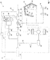
fig. 1 is a schematic view of a mobile operating machine according to the present invention; -
fig. 2 is a schematic view of a first functioning mode of the mobile operating machine offig. 1 ; -
fig. 3 is a schematic view of a second functioning mode of the mobile operating machine offig. 1 ; -
fig. 4 is a schematic view of a third functioning mode of the mobile operating machine offig. 1 ; -
fig. 5 is a schematic view of a fourth functioning mode of the mobile operating machine offig. 1 . - To facilitate comprehension, the same reference numbers have been used, where possible, to identify identical common elements in the drawings. It is understood that elements and characteristics of one embodiment can conveniently be combined or incorporated into other embodiments without further clarifications.
- With reference to
fig. 1 , a mobile operating machine, which in this case is a truck-mountedpump 10, is used for the distribution and delivery of concrete in operating sites, for example a construction site. - The
mobile operating machine 10 schematically comprises aconventional motor vehicle 11, represented in its entirety by a broken line, moved by anendothermic engine 12, such as a conventional diesel engine. - Mounted on the
motor vehicle 11 there is an articulatedarm 13 associated with anextendable pipe 32 for delivering concrete, apumping unit 15, and a stabilizingunit 16 which has the function of stabilizing themotor vehicle 11 once it has reached the operating site. - The
endothermic engine 12 is provided with adrive shaft 17 which allows to rotate atransmission shaft 19 of amovement unit 20, which is provided withwheels 21. Aclutch 22 and agearbox 23 of any known type can be associated with thedrive shaft 17, to determine the drive of themovement unit 20. - Furthermore, the
endothermic engine 12 is connected to at least a first power take-off 25 and a second power take-off 26 which are distinct from each other and can be activated selectively with respect to each other. - The
mobile operating machine 10 also comprises adrive apparatus 27, indicated in its entirety by a broken line, operatively connected to the power take-offs endothermic engine 12 and configured to drive the articulatedarm 13, thepumping unit 15, the stabilizingunit 16, as well as other electric orhydraulic service units 28 of theoperating machine 10. - In particular, the
drive apparatus 27 has a first drive axis, indicated by A1, associated with the first power take-off 25 and a second drive axis, indicated by A2, associated with the second power take-off 26. - A
hydraulic pump 29 is positioned along the first drive axis A1, operatively connected to the first power take-off 25 and configured to pump a work fluid to determine the selectively alternating drive of the articulatedarm 13 and the stabilizingunit 16. - In particular, the articulated
arm 13 comprises a plurality ofsections 30 reciprocally articulated and moved by respectivehydraulic actuators 31, or motors, and thepipe 32, associated with thesections 30, through which the concrete is pumped toward the delivery zone. Theactuators 31 are operatively connected to thehydraulic pump 29 which drives them by supplying them with the work fluid so that the articulatedarm 13 can assume the desired position. - The stabilizing
unit 16 comprises one ormore support devices 33, for example extendable support feet, preferably distributed symmetrically on the perimeter of theoperating machine 10. Thesupport devices 33 are also operatively connected to thehydraulic pump 29 which drives them, supplying them with the work fluid so that they can be moved to stabilize and secure theoperating machine 10 before and during pumping and delivery of the concrete. - The
drive apparatus 27 also comprises, disposed along the first drive axis A1 and operatively connected to each other, anelectric motor 35, provided with aconverter 36 which acts as an inverter, and connected in turn to thehydraulic pump 29, and anelectric accumulator 37. - In accordance with one aspect of the present invention, the
hydraulic pump 29 is the type which also allows the connection, and therefore the transmission of mechanical energy, from theendothermic engine 12 to theelectric motor 35. - In particular, the
electric motor 35 can assume at least a first operating condition in which it converts the electrical energy of theelectric accumulator 37 into mechanical energy to drive thehydraulic pump 29, and a second operating condition in which it converts the mechanical energy of theendothermic engine 12 into electrical energy to recharge theelectric accumulator 37. Therefore, theelectric motor 35 can function both as a motor and as a generator. - The
converter 36 is responsible for the control of theelectric motor 35, that is, the management of continuous and/or alternating electrical energy, and is operatively connected to theelectric accumulator 37. - The
electric accumulator 37 comprises, for example, one or more electric batteries and can be provided with aconnection device 39 configured to connect theelectric accumulator 37 to an electrical energy source, for example a normal electric network, when the energy level of theelectric accumulator 37 is low. - In accordance with another aspect of the present invention, along the first drive axis A1, between the first power take-
off 25 and thehydraulic pump 29, adisengagement device 40 is positioned, for example an overrun joint or free wheel, configured to selectively disconnect the first power take-off 25 of theendothermic engine 12 from thehydraulic pump 29 and from theelectric motor 35. - In particular, the
disengagement device 40, when it is connected, allows the transmission of the mechanical energy of theendothermic engine 12 to thehydraulic pump 29 and, possibly, to theelectric motor 35, which in this case acts as a generator to recharge theaccumulator 37, for example in the case of a KERS-type energy recovery system; on the contrary, when it is disconnected, it prevents the transmission of the mechanical energy generated by theelectric motor 35 toward theendothermic engine 12. - In this way, the articulated
arm 13 and the stabilizingunit 16 can function in hybrid mode, that is, alternatively, either by means of theendothermic engine 12 or by means of theelectric motor 35. - In particular, the preferential drive will take place through the
electric motor 35 and, at least in the event that the energy level in theaccumulator 37 falls below a certain threshold, the drive will be switched by means of theendothermic engine 12. - Along the second drive axis A2 of the
drive apparatus 27, operatively connected to the second power take-off 26, there is thepumping unit 15, that is, the unit suitable to pump concrete through thepipe 32 associated with the articulatedarm 13, and other electric orhydraulic service units 28. - The
mobile operating machine 10 also comprises acentral control unit 41 which is operatively connected at least to theendothermic engine 12, to theelectric motor 35 and to theelectric accumulator 37. - The
central control unit 41 is programmed to automatically manage both the hybrid mode of the articulatedarm 13 and the stabilizingunit 16, and also the start and stop of theendothermic engine 12, when thepumping unit 15 is activated and, respectively, deactivated, possibly to activate, for example, the stabilizingunit 16. - In particular, in the management of the hybrid mode, the
central control unit 41 is set so as to preferentially start theelectric motor 35 to drive thehydraulic pump 29, the stabilizingunit 16 to secure the operatingmachine 10 and therefore the articulatedarm 13. In this situation, as we said, theendothermic engine 12 can be started automatically in order to drive the articulatedarm 13 or the stabilizingunit 16 only when the level of energy accumulated in theelectric accumulator 37 is, or falls below a minimum energy threshold. - Of course, in the case of special needs, it is also possible to provide automatic management of the hybrid mode by the
central control unit 41, by setting a working mode other than the automatic one. - The functioning of the
mobile operating machine 10 described heretofore, which corresponds to the method according to the present invention, comprises at least four functioning modes F1, F2, F3, F4. - A first functioning mode F1 of the
mobile operating machine 10 according to the present invention is shown infig. 2 and comprises the following steps: - the
mobile operating machine 10 is moved by theendothermic engine 12, which drives themovement unit 20 to reach the desired position on a construction site; - the
mobile operating machine 10 is stationary and thedisengagement device 40 is deactivated, therefore theelectric motor 35 is disconnected from the first power take-off 25; - the
electric motor 35, in this case, assumes the first operating condition, that is, it takes electrical energy from theelectric accumulator 37 using theconverter 36, and then transforms it into mechanical drive energy to drive thehydraulic pump 29; - the
hydraulic pump 29 pumps the work fluid, driving the stabilizingunit 16, and causes the movement of one ormore support devices 33 so as to stabilize the operatingmachine 10; - then, the
hydraulic pump 29 pumps the work fluid, driving the articulatedarm 13 to position it in the desired position. - A second functioning mode F2 of the
mobile operating machine 10 according to the present invention is shown infig. 3 and comprises, in addition to the steps of the first functioning mode F1, the following step: - the
endothermic engine 12 is started and by means of the second power take-off 26 drives thepumping unit 15, which pumps the concrete through thepipe 32 of the articulatedarm 13 for final delivery. Possibly, in this step it is also possible to drive the other electric orhydraulic service units 28. - A third functioning mode F3 of the
mobile operating machine 10 according to the present invention is shown infig. 4 and comprises the following steps: - the
mobile operating machine 10 is moved by theendothermic engine 12, which drives themovement unit 20 to reach the desired position on a construction site; - the
mobile operating machine 10 is stationary and thedisengagement device 40 is activated; - the
endothermic engine 12 is driven and by means of the first power take-off 25 transmits mechanical energy to thehydraulic pump 29 in order to drive it; - the
hydraulic pump 29 pumps the work fluid, activating the stabilizingunit 16, and causes the lowering of one ormore support devices 33 in order to stabilize the operatingmachine 10 for the subsequent pumping and subsequent delivery of the concrete; - the
hydraulic pump 29 pumps the work fluid, driving the articulatedarm 13 to position it in the desired position; - by means of the second power take-
off 26, theendothermic engine 12 drives thepumping unit 15, which pumps the concrete through thepipe 32 of the articulatedarm 13 for final delivery. Possibly, in this step it is also possible to drive the other electric orhydraulic service units 28. - A fourth functioning mode F4 of the
mobile operating machine 10 according to the present invention is shown schematically infig. 5 and comprises the following steps: - the
mobile operating machine 10 is stationary and thedisengagement device 40 is activated; - the
endothermic engine 12 is driven and by means of the first power take-off 25 transmits mechanical energy to theelectric motor 35 which, in this case, assumes the second operating condition, in which by means of theelectronic converter 36 it transfers electrical energy to theelectric accumulator 37 in order to recharge it. - Furthermore, the
electric accumulator 37 can be connected, by means of theconnection device 39, to a source of electrical energy, for example to the electricity network, to be recharged. - The use of the
electric motor 35, compared to theendothermic engine 12, has the following advantages: - the
electric motor 35 has a higher working efficiency compared to the efficiency of theendothermic engine 12; - emissions of fumes harmful to both the environment and health are significantly reduced;
- noise pollution is significantly reduced.
- Furthermore, the positioning of the
disengagement device 40 along the first drive axis A1 has the advantage of allowing the management of the torque entering and/or leaving the first drive axis A1 without generating imbalances in theendothermic engine 12 of themotor vehicle 11, that is, without altering the behavior of theendothermic engine 12. - It is clear that modifications and/or additions of parts or steps may be made to the
mobile operating machine 10 and the functioning method as described heretofore, without departing from the field of the present invention as defined by the claims. - It is also clear that, although the present invention has been described with reference to a specific example, a person of skill in the art shall certainly be able to achieve many other equivalent forms of the mobile operating machine and the functioning method, having the characteristics as set forth in the claims and hence all coming within the field of protection defined thereby.
Claims (10)
- Mobile operating machine (10) comprising a motor vehicle (11) moved by an endothermic engine (12), an articulated arm (13) associated with a concrete delivery pipe (32), a pumping unit (15) suitable to pump concrete into said pipe (32) and a stabilizing unit (16) for stabilizing said operating machine (10) during the pumping and delivery of said concrete, characterized in that said endothermic engine (12) is provided with at least a first power take-off (25) and a second power take-off (26), distinct from the first power take-off (25), which can be activated selectively with respect to each other, in that at least one hydraulic pump (29) which drives said articulated arm (13) and said stabilizing unit (16), an electric motor (35) and an electric accumulator (37) are connected to said first power take-off (25) by means of a first drive axis (A1), and at least said pumping unit (15) is connected to said second power take-off (26) by means of a second drive axis (A2), distinct from said first drive axis (A1), and in that along said first power take-off (25) there is a disengagement device (40) which can be selectively activated to alternatively determine the drive of said hydraulic pump (29) by means of said endothermic engine (12), or by means of said electric motor (35).
- Mobile operating machine (10) as in claim 1, characterized in that said electric motor (35) is configured to assume at least a first operating condition, in which it converts the electrical energy of said electric accumulator (37) into mechanical energy that drives said hydraulic pump (29), and a second operating condition, in which it converts the mechanical energy of said endothermic engine (12) into electrical energy to recharge said electric accumulator (37).
- Mobile operating machine (10) as in claims 1 or 2, characterized in that said hydraulic pump (29) is of the type that allows the transmission of mechanical energy from said endothermic engine (12) to said electric motor (35).
- Mobile operating machine (10) as in claims 1, 2 or 3, characterized in that it comprises a converter (36) operatively connected to said electric motor (35) and to said electric accumulator (37) and configured to manage the direct and/or alternating electrical energy of said electric motor (35).
- Mobile operating machine (10) as in any claim hereinbefore, characterized in that said electric accumulator (37) is provided with a connection device (39) for the connection to a source of electrical energy.
- Mobile operating machine (10) as in any claim hereinbefore, characterized in that it comprises a central control unit (41) operatively connected at least to said endothermic engine (12), to said electric motor (35) and to said electric accumulator (37), and configured to automatically manage the drive of said hydraulic pump (29) by means of said electric motor (35), or by means of said endothermic engine (12).
- Mobile operating machine (10) as in claim 6, characterized in that said central control unit (41) is configured to also automatically manage the start and stop of said endothermic engine (12), when said pumping unit (15) is activated and, respectively, deactivated.
- Functioning method of a mobile operating machine (10) as in claims 1 to 7, in which at least a first functioning step it is provides in which said stabilizing unit (16) and said articulated arm (13) are driven by a hydraulic pump (29) powered by an electric motor (35) associated with electrical energy storage means of the accumulator type (37), and a second functioning step in which said pumping unit (15) is driven by means of said endothermic engine (12).
- Functioning method as in claim 8, characterized in that it provides at least one functioning step in which said stabilizing unit (16) and said articulated arm (13) are driven by the hydraulic pump (29), which is driven by said endothermic engine (12) in the event that the energy level in said electric accumulator (37) is below a determinate threshold.
- Functioning method as in claim 8 or 9, characterized in that it provides at least one step of recharging said electric accumulator (37) from a source of electrical energy and/or by means of said endothermic engine (12) passing through said hydraulic pump (29) and said electric motor (35).
Applications Claiming Priority (1)
| Application Number | Priority Date | Filing Date | Title |
|---|---|---|---|
| IT102021000015947A IT202100015947A1 (en) | 2021-06-18 | 2021-06-18 | MOBILE WORKING MACHINE AND METHOD OF OPERATION OF SUCH MOBILE WORKING MACHINE |
Publications (2)
| Publication Number | Publication Date |
|---|---|
| EP4105484A1 true EP4105484A1 (en) | 2022-12-21 |
| EP4105484B1 EP4105484B1 (en) | 2024-08-21 |
Family
ID=77989871
Family Applications (1)
| Application Number | Title | Priority Date | Filing Date |
|---|---|---|---|
| EP22179481.1A Active EP4105484B1 (en) | 2021-06-18 | 2022-06-16 | Mobile operating machine and fuctioning method of said mobile operating machine |
Country Status (5)
| Country | Link |
|---|---|
| US (1) | US20220402165A1 (en) |
| EP (1) | EP4105484B1 (en) |
| CN (1) | CN115492392A (en) |
| FI (1) | FI4105484T3 (en) |
| IT (1) | IT202100015947A1 (en) |
Cited By (1)
| Publication number | Priority date | Publication date | Assignee | Title |
|---|---|---|---|---|
| DE102023112171A1 (en) | 2023-05-09 | 2024-11-14 | Putzmeister Engineering Gmbh | construction machine |
Families Citing this family (3)
| Publication number | Priority date | Publication date | Assignee | Title |
|---|---|---|---|---|
| IT202100024436A1 (en) * | 2021-09-23 | 2023-03-23 | Cifa Spa | HYBRID MOBILE OPERATING MACHINE AND ITS OPERATING PROCEDURE |
| US20250115121A1 (en) * | 2023-10-09 | 2025-04-10 | Roger Hayes | Pump system for liquid transport tank |
| WO2025193909A1 (en) * | 2024-03-13 | 2025-09-18 | Lmi Us, Llc | Hybrid power system for hydraulic pump for concrete mixer |
Citations (8)
| Publication number | Priority date | Publication date | Assignee | Title |
|---|---|---|---|---|
| DE2737884A1 (en) * | 1977-08-23 | 1979-03-08 | Schlecht Karl | Saddle-back chassis-mounted concrete distributing pump - has pump filler funnel at vehicle front with lowerable pair of shafts |
| CN1837551A (en) * | 2006-04-14 | 2006-09-27 | 梁毅 | Walking concrete pumping arm support conveyor |
| CN102605958A (en) * | 2012-04-12 | 2012-07-25 | 三一重工股份有限公司 | Cantilever crane device and engineering machinery |
| CN102562096B (en) * | 2012-02-09 | 2014-06-25 | 上海汽车改装厂有限公司 | Control system and self-travelling type construction machinery with same |
| US9850671B2 (en) | 2014-11-24 | 2017-12-26 | Cifa Spa | Vehicle to project concrete |
| EP3591141A1 (en) * | 2018-07-02 | 2020-01-08 | CIFA SpA | Drive apparatus of a mobile operating machine and mobile operating machine comprising said drive apparatus |
| DE102018214965A1 (en) | 2018-09-04 | 2020-03-05 | Putzmeister Engineering Gmbh | Truck-mounted concrete pump |
| DE202020101432U1 (en) * | 2020-03-16 | 2021-06-17 | Liebherr-Mischtechnik Gmbh | Truck-mounted concrete pump |
Family Cites Families (1)
| Publication number | Priority date | Publication date | Assignee | Title |
|---|---|---|---|---|
| IT201800006838A1 (en) * | 2018-07-02 | 2020-01-02 | MOBILE OPERATING MACHINE AND METHOD OF OPERATION OF SUCH MOBILE OPERATING MACHINE |
-
2021
- 2021-06-18 IT IT102021000015947A patent/IT202100015947A1/en unknown
-
2022
- 2022-06-16 EP EP22179481.1A patent/EP4105484B1/en active Active
- 2022-06-16 FI FIEP22179481.1T patent/FI4105484T3/en active
- 2022-06-20 CN CN202210700476.0A patent/CN115492392A/en active Pending
- 2022-06-21 US US17/844,987 patent/US20220402165A1/en active Pending
Patent Citations (8)
| Publication number | Priority date | Publication date | Assignee | Title |
|---|---|---|---|---|
| DE2737884A1 (en) * | 1977-08-23 | 1979-03-08 | Schlecht Karl | Saddle-back chassis-mounted concrete distributing pump - has pump filler funnel at vehicle front with lowerable pair of shafts |
| CN1837551A (en) * | 2006-04-14 | 2006-09-27 | 梁毅 | Walking concrete pumping arm support conveyor |
| CN102562096B (en) * | 2012-02-09 | 2014-06-25 | 上海汽车改装厂有限公司 | Control system and self-travelling type construction machinery with same |
| CN102605958A (en) * | 2012-04-12 | 2012-07-25 | 三一重工股份有限公司 | Cantilever crane device and engineering machinery |
| US9850671B2 (en) | 2014-11-24 | 2017-12-26 | Cifa Spa | Vehicle to project concrete |
| EP3591141A1 (en) * | 2018-07-02 | 2020-01-08 | CIFA SpA | Drive apparatus of a mobile operating machine and mobile operating machine comprising said drive apparatus |
| DE102018214965A1 (en) | 2018-09-04 | 2020-03-05 | Putzmeister Engineering Gmbh | Truck-mounted concrete pump |
| DE202020101432U1 (en) * | 2020-03-16 | 2021-06-17 | Liebherr-Mischtechnik Gmbh | Truck-mounted concrete pump |
Cited By (1)
| Publication number | Priority date | Publication date | Assignee | Title |
|---|---|---|---|---|
| DE102023112171A1 (en) | 2023-05-09 | 2024-11-14 | Putzmeister Engineering Gmbh | construction machine |
Also Published As
| Publication number | Publication date |
|---|---|
| FI4105484T3 (en) | 2024-11-18 |
| IT202100015947A1 (en) | 2022-12-18 |
| EP4105484B1 (en) | 2024-08-21 |
| CN115492392A (en) | 2022-12-20 |
| US20220402165A1 (en) | 2022-12-22 |
Similar Documents
| Publication | Publication Date | Title |
|---|---|---|
| EP4105484B1 (en) | Mobile operating machine and fuctioning method of said mobile operating machine | |
| US11084367B2 (en) | Mining machine and energy storage system for same | |
| EP3023212B1 (en) | Vehicle to project concrete | |
| EP3591142B1 (en) | Mobile operating machine and functioning method of said mobile operating machine | |
| EP3591141B1 (en) | Mobile operating machine with hybrid drive apparatus | |
| EP1967486B1 (en) | Mobile work platform | |
| JP4864778B2 (en) | Tunnel work vehicle | |
| US9315094B2 (en) | Working vehicle | |
| US11933058B2 (en) | Hybrid mobile operating machine and its functioning method | |
| AU2016321671B2 (en) | Electrically driven working machine comprising reverse power storage | |
| CN111114306A (en) | Construction machine | |
| JP2014046997A (en) | Work machine | |
| JP2018528896A (en) | Track construction machinery | |
| JP6076140B2 (en) | External power judgment device for work machines | |
| JP3156458U (en) | Concrete mixer truck | |
| EP3924201B1 (en) | Arrangement and method for hybrid power generation | |
| JP2017082732A (en) | Engine stop control device | |
| JP2014046706A (en) | Work machine |
Legal Events
| Date | Code | Title | Description |
|---|---|---|---|
| PUAI | Public reference made under article 153(3) epc to a published international application that has entered the european phase |
Free format text: ORIGINAL CODE: 0009012 |
|
| STAA | Information on the status of an ep patent application or granted ep patent |
Free format text: STATUS: THE APPLICATION HAS BEEN PUBLISHED |
|
| AK | Designated contracting states |
Kind code of ref document: A1 Designated state(s): AL AT BE BG CH CY CZ DE DK EE ES FI FR GB GR HR HU IE IS IT LI LT LU LV MC MK MT NL NO PL PT RO RS SE SI SK SM TR |
|
| STAA | Information on the status of an ep patent application or granted ep patent |
Free format text: STATUS: REQUEST FOR EXAMINATION WAS MADE |
|
| P01 | Opt-out of the competence of the unified patent court (upc) registered |
Effective date: 20230521 |
|
| 17P | Request for examination filed |
Effective date: 20230529 |
|
| RBV | Designated contracting states (corrected) |
Designated state(s): AL AT BE BG CH CY CZ DE DK EE ES FI FR GB GR HR HU IE IS IT LI LT LU LV MC MK MT NL NO PL PT RO RS SE SI SK SM TR |
|
| REG | Reference to a national code |
Ref country code: DE Ref legal event code: R079 Free format text: PREVIOUS MAIN CLASS: F04B0049060000 Ipc: F04B0015020000 Ref country code: DE Ref legal event code: R079 Ref document number: 602022005438 Country of ref document: DE Free format text: PREVIOUS MAIN CLASS: F04B0049060000 Ipc: F04B0015020000 |
|
| GRAP | Despatch of communication of intention to grant a patent |
Free format text: ORIGINAL CODE: EPIDOSNIGR1 |
|
| STAA | Information on the status of an ep patent application or granted ep patent |
Free format text: STATUS: GRANT OF PATENT IS INTENDED |
|
| RIC1 | Information provided on ipc code assigned before grant |
Ipc: F04B 35/00 20060101ALI20240221BHEP Ipc: F04B 35/06 20060101ALI20240221BHEP Ipc: F04B 15/02 20060101AFI20240221BHEP |
|
| INTG | Intention to grant announced |
Effective date: 20240311 |
|
| GRAS | Grant fee paid |
Free format text: ORIGINAL CODE: EPIDOSNIGR3 |
|
| GRAA | (expected) grant |
Free format text: ORIGINAL CODE: 0009210 |
|
| STAA | Information on the status of an ep patent application or granted ep patent |
Free format text: STATUS: THE PATENT HAS BEEN GRANTED |
|
| AK | Designated contracting states |
Kind code of ref document: B1 Designated state(s): AL AT BE BG CH CY CZ DE DK EE ES FI FR GB GR HR HU IE IS IT LI LT LU LV MC MK MT NL NO PL PT RO RS SE SI SK SM TR |
|
| REG | Reference to a national code |
Ref country code: GB Ref legal event code: FG4D |
|
| REG | Reference to a national code |
Ref country code: CH Ref legal event code: EP |
|
| REG | Reference to a national code |
Ref country code: IE Ref legal event code: FG4D |
|
| REG | Reference to a national code |
Ref country code: DE Ref legal event code: R096 Ref document number: 602022005438 Country of ref document: DE |
|
| REG | Reference to a national code |
Ref country code: FI Ref legal event code: FGE |
|
| REG | Reference to a national code |
Ref country code: NL Ref legal event code: FP |
|
| REG | Reference to a national code |
Ref country code: SE Ref legal event code: TRGR |
|
| REG | Reference to a national code |
Ref country code: LT Ref legal event code: MG9D |
|
| PG25 | Lapsed in a contracting state [announced via postgrant information from national office to epo] |
Ref country code: PT Free format text: LAPSE BECAUSE OF FAILURE TO SUBMIT A TRANSLATION OF THE DESCRIPTION OR TO PAY THE FEE WITHIN THE PRESCRIBED TIME-LIMIT Effective date: 20241223 Ref country code: PL Free format text: LAPSE BECAUSE OF FAILURE TO SUBMIT A TRANSLATION OF THE DESCRIPTION OR TO PAY THE FEE WITHIN THE PRESCRIBED TIME-LIMIT Effective date: 20240821 Ref country code: GR Free format text: LAPSE BECAUSE OF FAILURE TO SUBMIT A TRANSLATION OF THE DESCRIPTION OR TO PAY THE FEE WITHIN THE PRESCRIBED TIME-LIMIT Effective date: 20241122 |
|
| PG25 | Lapsed in a contracting state [announced via postgrant information from national office to epo] |
Ref country code: BG Free format text: LAPSE BECAUSE OF FAILURE TO SUBMIT A TRANSLATION OF THE DESCRIPTION OR TO PAY THE FEE WITHIN THE PRESCRIBED TIME-LIMIT Effective date: 20240821 |
|
| PG25 | Lapsed in a contracting state [announced via postgrant information from national office to epo] |
Ref country code: LV Free format text: LAPSE BECAUSE OF FAILURE TO SUBMIT A TRANSLATION OF THE DESCRIPTION OR TO PAY THE FEE WITHIN THE PRESCRIBED TIME-LIMIT Effective date: 20240821 |
|
| PG25 | Lapsed in a contracting state [announced via postgrant information from national office to epo] |
Ref country code: IS Free format text: LAPSE BECAUSE OF FAILURE TO SUBMIT A TRANSLATION OF THE DESCRIPTION OR TO PAY THE FEE WITHIN THE PRESCRIBED TIME-LIMIT Effective date: 20241221 |
|
| PG25 | Lapsed in a contracting state [announced via postgrant information from national office to epo] |
Ref country code: HR Free format text: LAPSE BECAUSE OF FAILURE TO SUBMIT A TRANSLATION OF THE DESCRIPTION OR TO PAY THE FEE WITHIN THE PRESCRIBED TIME-LIMIT Effective date: 20240821 |
|
| PG25 | Lapsed in a contracting state [announced via postgrant information from national office to epo] |
Ref country code: ES Free format text: LAPSE BECAUSE OF FAILURE TO SUBMIT A TRANSLATION OF THE DESCRIPTION OR TO PAY THE FEE WITHIN THE PRESCRIBED TIME-LIMIT Effective date: 20240821 Ref country code: RS Free format text: LAPSE BECAUSE OF FAILURE TO SUBMIT A TRANSLATION OF THE DESCRIPTION OR TO PAY THE FEE WITHIN THE PRESCRIBED TIME-LIMIT Effective date: 20241121 |
|
| PG25 | Lapsed in a contracting state [announced via postgrant information from national office to epo] |
Ref country code: RS Free format text: LAPSE BECAUSE OF FAILURE TO SUBMIT A TRANSLATION OF THE DESCRIPTION OR TO PAY THE FEE WITHIN THE PRESCRIBED TIME-LIMIT Effective date: 20241121 Ref country code: PT Free format text: LAPSE BECAUSE OF FAILURE TO SUBMIT A TRANSLATION OF THE DESCRIPTION OR TO PAY THE FEE WITHIN THE PRESCRIBED TIME-LIMIT Effective date: 20241223 Ref country code: PL Free format text: LAPSE BECAUSE OF FAILURE TO SUBMIT A TRANSLATION OF THE DESCRIPTION OR TO PAY THE FEE WITHIN THE PRESCRIBED TIME-LIMIT Effective date: 20240821 Ref country code: LV Free format text: LAPSE BECAUSE OF FAILURE TO SUBMIT A TRANSLATION OF THE DESCRIPTION OR TO PAY THE FEE WITHIN THE PRESCRIBED TIME-LIMIT Effective date: 20240821 Ref country code: IS Free format text: LAPSE BECAUSE OF FAILURE TO SUBMIT A TRANSLATION OF THE DESCRIPTION OR TO PAY THE FEE WITHIN THE PRESCRIBED TIME-LIMIT Effective date: 20241221 Ref country code: HR Free format text: LAPSE BECAUSE OF FAILURE TO SUBMIT A TRANSLATION OF THE DESCRIPTION OR TO PAY THE FEE WITHIN THE PRESCRIBED TIME-LIMIT Effective date: 20240821 Ref country code: GR Free format text: LAPSE BECAUSE OF FAILURE TO SUBMIT A TRANSLATION OF THE DESCRIPTION OR TO PAY THE FEE WITHIN THE PRESCRIBED TIME-LIMIT Effective date: 20241122 Ref country code: ES Free format text: LAPSE BECAUSE OF FAILURE TO SUBMIT A TRANSLATION OF THE DESCRIPTION OR TO PAY THE FEE WITHIN THE PRESCRIBED TIME-LIMIT Effective date: 20240821 Ref country code: BG Free format text: LAPSE BECAUSE OF FAILURE TO SUBMIT A TRANSLATION OF THE DESCRIPTION OR TO PAY THE FEE WITHIN THE PRESCRIBED TIME-LIMIT Effective date: 20240821 |
|
| PG25 | Lapsed in a contracting state [announced via postgrant information from national office to epo] |
Ref country code: SM Free format text: LAPSE BECAUSE OF FAILURE TO SUBMIT A TRANSLATION OF THE DESCRIPTION OR TO PAY THE FEE WITHIN THE PRESCRIBED TIME-LIMIT Effective date: 20240821 Ref country code: DK Free format text: LAPSE BECAUSE OF FAILURE TO SUBMIT A TRANSLATION OF THE DESCRIPTION OR TO PAY THE FEE WITHIN THE PRESCRIBED TIME-LIMIT Effective date: 20240821 Ref country code: RO Free format text: LAPSE BECAUSE OF FAILURE TO SUBMIT A TRANSLATION OF THE DESCRIPTION OR TO PAY THE FEE WITHIN THE PRESCRIBED TIME-LIMIT Effective date: 20240821 |
|
| PG25 | Lapsed in a contracting state [announced via postgrant information from national office to epo] |
Ref country code: EE Free format text: LAPSE BECAUSE OF FAILURE TO SUBMIT A TRANSLATION OF THE DESCRIPTION OR TO PAY THE FEE WITHIN THE PRESCRIBED TIME-LIMIT Effective date: 20240821 |
|
| PG25 | Lapsed in a contracting state [announced via postgrant information from national office to epo] |
Ref country code: CZ Free format text: LAPSE BECAUSE OF FAILURE TO SUBMIT A TRANSLATION OF THE DESCRIPTION OR TO PAY THE FEE WITHIN THE PRESCRIBED TIME-LIMIT Effective date: 20240821 |
|
| PG25 | Lapsed in a contracting state [announced via postgrant information from national office to epo] |
Ref country code: SK Free format text: LAPSE BECAUSE OF FAILURE TO SUBMIT A TRANSLATION OF THE DESCRIPTION OR TO PAY THE FEE WITHIN THE PRESCRIBED TIME-LIMIT Effective date: 20240821 |
|
| REG | Reference to a national code |
Ref country code: DE Ref legal event code: R097 Ref document number: 602022005438 Country of ref document: DE |
|
| PLBE | No opposition filed within time limit |
Free format text: ORIGINAL CODE: 0009261 |
|
| STAA | Information on the status of an ep patent application or granted ep patent |
Free format text: STATUS: NO OPPOSITION FILED WITHIN TIME LIMIT |
|
| PGFP | Annual fee paid to national office [announced via postgrant information from national office to epo] |
Ref country code: FI Payment date: 20250624 Year of fee payment: 4 |
|
| PGFP | Annual fee paid to national office [announced via postgrant information from national office to epo] |
Ref country code: DE Payment date: 20250626 Year of fee payment: 4 |
|
| PGFP | Annual fee paid to national office [announced via postgrant information from national office to epo] |
Ref country code: NO Payment date: 20250624 Year of fee payment: 4 |
|
| PGFP | Annual fee paid to national office [announced via postgrant information from national office to epo] |
Ref country code: NL Payment date: 20250624 Year of fee payment: 4 Ref country code: BE Payment date: 20250624 Year of fee payment: 4 |
|
| PGFP | Annual fee paid to national office [announced via postgrant information from national office to epo] |
Ref country code: FR Payment date: 20250623 Year of fee payment: 4 |
|
| PGFP | Annual fee paid to national office [announced via postgrant information from national office to epo] |
Ref country code: AT Payment date: 20250721 Year of fee payment: 4 |
|
| 26N | No opposition filed |
Effective date: 20250522 |
|
| PGFP | Annual fee paid to national office [announced via postgrant information from national office to epo] |
Ref country code: SE Payment date: 20250619 Year of fee payment: 4 |
|
| PGFP | Annual fee paid to national office [announced via postgrant information from national office to epo] |
Ref country code: IT Payment date: 20250630 Year of fee payment: 4 |
|
| REG | Reference to a national code |
Ref country code: AT Ref legal event code: UEP Ref document number: 1715697 Country of ref document: AT Kind code of ref document: T Effective date: 20240821 |
|
| PGFP | Annual fee paid to national office [announced via postgrant information from national office to epo] |
Ref country code: CH Payment date: 20250701 Year of fee payment: 4 |
|
| PG25 | Lapsed in a contracting state [announced via postgrant information from national office to epo] |
Ref country code: MC Free format text: LAPSE BECAUSE OF FAILURE TO SUBMIT A TRANSLATION OF THE DESCRIPTION OR TO PAY THE FEE WITHIN THE PRESCRIBED TIME-LIMIT Effective date: 20240821 |
|
| PG25 | Lapsed in a contracting state [announced via postgrant information from national office to epo] |
Ref country code: LU Free format text: LAPSE BECAUSE OF NON-PAYMENT OF DUE FEES Effective date: 20250616 |
|
| PG25 | Lapsed in a contracting state [announced via postgrant information from national office to epo] |
Ref country code: IE Free format text: LAPSE BECAUSE OF NON-PAYMENT OF DUE FEES Effective date: 20250616 |