EP4105465A2 - Oil cooling system for aircraft engine - Google Patents
Oil cooling system for aircraft engine Download PDFInfo
- Publication number
- EP4105465A2 EP4105465A2 EP22179738.4A EP22179738A EP4105465A2 EP 4105465 A2 EP4105465 A2 EP 4105465A2 EP 22179738 A EP22179738 A EP 22179738A EP 4105465 A2 EP4105465 A2 EP 4105465A2
- Authority
- EP
- European Patent Office
- Prior art keywords
- oil
- heat exchanger
- flow
- bypass
- passage
- Prior art date
- Legal status (The legal status is an assumption and is not a legal conclusion. Google has not performed a legal analysis and makes no representation as to the accuracy of the status listed.)
- Pending
Links
Images

Classifications
-
- F—MECHANICAL ENGINEERING; LIGHTING; HEATING; WEAPONS; BLASTING
- F02—COMBUSTION ENGINES; HOT-GAS OR COMBUSTION-PRODUCT ENGINE PLANTS
- F02C—GAS-TURBINE PLANTS; AIR INTAKES FOR JET-PROPULSION PLANTS; CONTROLLING FUEL SUPPLY IN AIR-BREATHING JET-PROPULSION PLANTS
- F02C7/00—Features, components parts, details or accessories, not provided for in, or of interest apart form groups F02C1/00 - F02C6/00; Air intakes for jet-propulsion plants
- F02C7/12—Cooling of plants
- F02C7/14—Cooling of plants of fluids in the plant, e.g. lubricant or fuel
-
- F—MECHANICAL ENGINEERING; LIGHTING; HEATING; WEAPONS; BLASTING
- F01—MACHINES OR ENGINES IN GENERAL; ENGINE PLANTS IN GENERAL; STEAM ENGINES
- F01D—NON-POSITIVE DISPLACEMENT MACHINES OR ENGINES, e.g. STEAM TURBINES
- F01D25/00—Component parts, details, or accessories, not provided for in, or of interest apart from, other groups
- F01D25/18—Lubricating arrangements
- F01D25/20—Lubricating arrangements using lubrication pumps
-
- F—MECHANICAL ENGINEERING; LIGHTING; HEATING; WEAPONS; BLASTING
- F02—COMBUSTION ENGINES; HOT-GAS OR COMBUSTION-PRODUCT ENGINE PLANTS
- F02C—GAS-TURBINE PLANTS; AIR INTAKES FOR JET-PROPULSION PLANTS; CONTROLLING FUEL SUPPLY IN AIR-BREATHING JET-PROPULSION PLANTS
- F02C7/00—Features, components parts, details or accessories, not provided for in, or of interest apart form groups F02C1/00 - F02C6/00; Air intakes for jet-propulsion plants
- F02C7/06—Arrangements of bearings; Lubricating
-
- F—MECHANICAL ENGINEERING; LIGHTING; HEATING; WEAPONS; BLASTING
- F16—ENGINEERING ELEMENTS AND UNITS; GENERAL MEASURES FOR PRODUCING AND MAINTAINING EFFECTIVE FUNCTIONING OF MACHINES OR INSTALLATIONS; THERMAL INSULATION IN GENERAL
- F16N—LUBRICATING
- F16N39/00—Arrangements for conditioning of lubricants in the lubricating system
-
- F—MECHANICAL ENGINEERING; LIGHTING; HEATING; WEAPONS; BLASTING
- F16—ENGINEERING ELEMENTS AND UNITS; GENERAL MEASURES FOR PRODUCING AND MAINTAINING EFFECTIVE FUNCTIONING OF MACHINES OR INSTALLATIONS; THERMAL INSULATION IN GENERAL
- F16N—LUBRICATING
- F16N39/00—Arrangements for conditioning of lubricants in the lubricating system
- F16N39/02—Arrangements for conditioning of lubricants in the lubricating system by cooling
-
- F—MECHANICAL ENGINEERING; LIGHTING; HEATING; WEAPONS; BLASTING
- F16—ENGINEERING ELEMENTS AND UNITS; GENERAL MEASURES FOR PRODUCING AND MAINTAINING EFFECTIVE FUNCTIONING OF MACHINES OR INSTALLATIONS; THERMAL INSULATION IN GENERAL
- F16N—LUBRICATING
- F16N39/00—Arrangements for conditioning of lubricants in the lubricating system
- F16N39/06—Arrangements for conditioning of lubricants in the lubricating system by filtration
-
- F—MECHANICAL ENGINEERING; LIGHTING; HEATING; WEAPONS; BLASTING
- F16—ENGINEERING ELEMENTS AND UNITS; GENERAL MEASURES FOR PRODUCING AND MAINTAINING EFFECTIVE FUNCTIONING OF MACHINES OR INSTALLATIONS; THERMAL INSULATION IN GENERAL
- F16N—LUBRICATING
- F16N7/00—Arrangements for supplying oil or unspecified lubricant from a stationary reservoir or the equivalent in or on the machine or member to be lubricated
- F16N7/38—Arrangements for supplying oil or unspecified lubricant from a stationary reservoir or the equivalent in or on the machine or member to be lubricated with a separate pump; Central lubrication systems
- F16N7/385—Central lubrication systems
-
- F—MECHANICAL ENGINEERING; LIGHTING; HEATING; WEAPONS; BLASTING
- F02—COMBUSTION ENGINES; HOT-GAS OR COMBUSTION-PRODUCT ENGINE PLANTS
- F02C—GAS-TURBINE PLANTS; AIR INTAKES FOR JET-PROPULSION PLANTS; CONTROLLING FUEL SUPPLY IN AIR-BREATHING JET-PROPULSION PLANTS
- F02C7/00—Features, components parts, details or accessories, not provided for in, or of interest apart form groups F02C1/00 - F02C6/00; Air intakes for jet-propulsion plants
- F02C7/22—Fuel supply systems
- F02C7/224—Heating fuel before feeding to the burner
-
- F—MECHANICAL ENGINEERING; LIGHTING; HEATING; WEAPONS; BLASTING
- F02—COMBUSTION ENGINES; HOT-GAS OR COMBUSTION-PRODUCT ENGINE PLANTS
- F02K—JET-PROPULSION PLANTS
- F02K3/00—Plants including a gas turbine driving a compressor or a ducted fan
- F02K3/08—Plants including a gas turbine driving a compressor or a ducted fan with supplementary heating of the working fluid; Control thereof
- F02K3/105—Heating the by-pass flow
- F02K3/115—Heating the by-pass flow by means of indirect heat exchange
-
- F—MECHANICAL ENGINEERING; LIGHTING; HEATING; WEAPONS; BLASTING
- F05—INDEXING SCHEMES RELATING TO ENGINES OR PUMPS IN VARIOUS SUBCLASSES OF CLASSES F01-F04
- F05D—INDEXING SCHEME FOR ASPECTS RELATING TO NON-POSITIVE-DISPLACEMENT MACHINES OR ENGINES, GAS-TURBINES OR JET-PROPULSION PLANTS
- F05D2220/00—Application
- F05D2220/30—Application in turbines
- F05D2220/32—Application in turbines in gas turbines
- F05D2220/323—Application in turbines in gas turbines for aircraft propulsion, e.g. jet engines
-
- F—MECHANICAL ENGINEERING; LIGHTING; HEATING; WEAPONS; BLASTING
- F05—INDEXING SCHEMES RELATING TO ENGINES OR PUMPS IN VARIOUS SUBCLASSES OF CLASSES F01-F04
- F05D—INDEXING SCHEME FOR ASPECTS RELATING TO NON-POSITIVE-DISPLACEMENT MACHINES OR ENGINES, GAS-TURBINES OR JET-PROPULSION PLANTS
- F05D2260/00—Function
- F05D2260/20—Heat transfer, e.g. cooling
-
- F—MECHANICAL ENGINEERING; LIGHTING; HEATING; WEAPONS; BLASTING
- F05—INDEXING SCHEMES RELATING TO ENGINES OR PUMPS IN VARIOUS SUBCLASSES OF CLASSES F01-F04
- F05D—INDEXING SCHEME FOR ASPECTS RELATING TO NON-POSITIVE-DISPLACEMENT MACHINES OR ENGINES, GAS-TURBINES OR JET-PROPULSION PLANTS
- F05D2260/00—Function
- F05D2260/20—Heat transfer, e.g. cooling
- F05D2260/213—Heat transfer, e.g. cooling by the provision of a heat exchanger within the cooling circuit
-
- F—MECHANICAL ENGINEERING; LIGHTING; HEATING; WEAPONS; BLASTING
- F05—INDEXING SCHEMES RELATING TO ENGINES OR PUMPS IN VARIOUS SUBCLASSES OF CLASSES F01-F04
- F05D—INDEXING SCHEME FOR ASPECTS RELATING TO NON-POSITIVE-DISPLACEMENT MACHINES OR ENGINES, GAS-TURBINES OR JET-PROPULSION PLANTS
- F05D2260/00—Function
- F05D2260/98—Lubrication
-
- F—MECHANICAL ENGINEERING; LIGHTING; HEATING; WEAPONS; BLASTING
- F16—ENGINEERING ELEMENTS AND UNITS; GENERAL MEASURES FOR PRODUCING AND MAINTAINING EFFECTIVE FUNCTIONING OF MACHINES OR INSTALLATIONS; THERMAL INSULATION IN GENERAL
- F16N—LUBRICATING
- F16N2210/00—Applications
- F16N2210/02—Turbines
-
- F—MECHANICAL ENGINEERING; LIGHTING; HEATING; WEAPONS; BLASTING
- F16—ENGINEERING ELEMENTS AND UNITS; GENERAL MEASURES FOR PRODUCING AND MAINTAINING EFFECTIVE FUNCTIONING OF MACHINES OR INSTALLATIONS; THERMAL INSULATION IN GENERAL
- F16N—LUBRICATING
- F16N2210/00—Applications
- F16N2210/08—Aircraft
-
- F—MECHANICAL ENGINEERING; LIGHTING; HEATING; WEAPONS; BLASTING
- F16—ENGINEERING ELEMENTS AND UNITS; GENERAL MEASURES FOR PRODUCING AND MAINTAINING EFFECTIVE FUNCTIONING OF MACHINES OR INSTALLATIONS; THERMAL INSULATION IN GENERAL
- F16N—LUBRICATING
- F16N2210/00—Applications
- F16N2210/12—Gearings
-
- Y—GENERAL TAGGING OF NEW TECHNOLOGICAL DEVELOPMENTS; GENERAL TAGGING OF CROSS-SECTIONAL TECHNOLOGIES SPANNING OVER SEVERAL SECTIONS OF THE IPC; TECHNICAL SUBJECTS COVERED BY FORMER USPC CROSS-REFERENCE ART COLLECTIONS [XRACs] AND DIGESTS
- Y02—TECHNOLOGIES OR APPLICATIONS FOR MITIGATION OR ADAPTATION AGAINST CLIMATE CHANGE
- Y02T—CLIMATE CHANGE MITIGATION TECHNOLOGIES RELATED TO TRANSPORTATION
- Y02T50/00—Aeronautics or air transport
- Y02T50/60—Efficient propulsion technologies, e.g. for aircraft
Definitions
- the application relates generally to aircraft engines and, more particularly, to lubrication systems of aircraft engines.
- a typical aircraft engine has a lubrication system to meet the lubrication and cooling needs of various components of the engine.
- the lubrication system can deliver oil from an oil tank to the various components within the engine, recover the used oil from the components, and return the recovered used oil back to the oil tank for recirculation.
- Some aircraft engines can include one or more heat exchangers to remove heat from the oil.
- the cooling requirements can vary depending on the operating conditions of the aircraft engine. Providing oil cooling that can adapt to the operating conditions of the aircraft engine can affect cost, size, weight and complexity of a cooling system. Improvement is desirable.
- an oil cooling system for an aircraft engine comprising:
- a bypass valve for an oil cooling system of an aircraft engine comprising:
- a method of cooling oil of an aircraft engine comprising:
- the systems and methods described herein may provide an oil cooling approach that is at least partially adaptive to cooling needs in a relatively simple, compact and cost-effective manner.
- the systems and methods described herein may facilitate ability to apportion the amount of heat rejection from the oil to air, and from the oil to fuel based on operating conditions.
- the ability to control cooling of the oil may be performed in a relatively passive manner.
- engaged and connected may include both direct engagement or connection (in which two elements contact each other) and indirect engagement or connection (in which at least one additional element is located between the two elements).
- Fig. 1 illustrates an aircraft engine depicted as a gas turbine engine 10 of a type preferably provided for use in subsonic flight, generally comprising in serial flow communication a fan 12 through which ambient air is propelled, a compressor section 14 for pressurizing the air, a combustor 16 in which the compressed air is mixed with fuel and ignited for generating an annular stream of hot combustion gases, and a turbine section 18 for extracting energy from the combustion gases.
- the gas turbine engine 10 has a core gas path including an intake 19 for receiving air.
- the compressor section 14 has at least one compressor 20 extending across the core gas path and the turbine section 18 has at least one turbine 22 extending across the core gas path, with the at least one compressor 20 and the at least one turbine 22 being rotatable with a shaft 24 rotatably supported within the gas turbine engine 10 by bearings 26.
- An oil system 28 is provided for circulating oil to the bearings 26 and back to an oil tank 30.
- the oil system 28 may service one or more lubrication loads such as bearings and/or gears that require lubrication and/or cooling.
- any aircraft engines such as internal combustion engines (e.g., piston engine, rotary engine), any type of gas turbine engines, (e.g., turbofan, turboshaft, and turboprop), and auxiliary power units.
- internal combustion engines e.g., piston engine, rotary engine
- gas turbine engines e.g., turbofan, turboshaft, and turboprop
- auxiliary power units e.g., auxiliary power units.
- the gas turbine engine 10 has a oil cooling system 40 that is used to exchange heat between different fluids for proper operation of the gas turbine engine 10.
- the oil cooling system 40 includes a first heat exchanger 41, which may be referred to as a air-cooled oil cooler (ACOC), which is used to transfer heat from the oil to an environment E outside the gas turbine engine 10 via a bypass airflow flowing in an annular bypass duct of the gas turbine engine 10.
- the first heat exchanger 41 includes an oil conduit 41A and fins 41B. The heat from the oil may be transferred to the fins 41B by conduction and from the fins 41B to the environment E by convection.
- the oil cooling system 40 may further include a second heat exchanger 42, which may be referred to as a fuel-oil heat exchanger (FOHE), used for transferring heat from the oil of the oil system 28 to fuel flowing from a fuel tank 31, or any other fuel source, to the combustor 16 of the gas turbine engine 10 for combustion. Pre-heating the fuel as such may increase efficiency of the combustion of the fuel and may cool down the oil that heats up while lubricating the bearings 26 or other lubrication load(s).
- FHE fuel-oil heat exchanger
- the oil system 28 includes an oil pump 32 that drives an oil flow F1 within an oil conduit 33 from the oil tank 30.
- the oil flow F1 then exchanges heat with an airflow F2 through the first heat exchanger 41, and then exchanges heat with a fuel flow F3 through the second heat exchanger 42.
- the oil flow F1 is then distributed between different components (lubrication load(s)) in need of oil.
- the oil flow F1 is injected into bearing cavities and a gearbox.
- Used oil is then scavenged, and scavenge pump(s) 34 drive a scavenge oil flow F4 from scavenge outlets of the bearing cavities and the gearbox back to the oil tank 30 where the oil may be directed back to the oil pump 32 and recirculated.
- a de-oiler and/or de-aerator may be used to remove air from the scavenge oil flow F4.
- the first heat exchanger 41 may be used to transfer heat from the oil flow F1 to the airflow F2. This may decrease a temperature of the oil flow F1. Then, the oil flow F1 may flow through the second heat exchanger 42 where it transfers additional heat to the fuel in order to cool the oil further.
- heat may be transferred from the oil to the fuel to heat the fuel to about 32 Fahrenheit (0°C) or higher. In some operating conditions, and more specifically when the gas turbine engine 10 is still warming up, the oil may not need to be cooled down with the air flow F2 before being directed through the second heat exchanger 42.
- the oil flow F1 (e.g., see flow F5) around the first heat exchanger 41 such that some of the oil flow F1 bypasses the first heat exchanger 41.
- Bypassing the first heat exchanger 41 may allow the oil to be at a higher temperature when it is injected in the second heat exchanger 42. Hence, more heat from the oil may be available to transfer to the fuel flow F3 when the first heat exchanger is bypassed.
- a bypass 35 (i.e., bypass oil passage) may be connected to the oil conduit 33 at two connection points being respectively upstream and downstream of the first heat exchanger 41.
- the bypass 35 has a bypass inlet 35A fluidly connected to the oil conduit 33 upstream of the first heat exchanger 41 and a bypass outlet 35B fluidly connected to the oil conduit 33 downstream of the first heat exchanger 41 and upstream of the second heat exchanger 42.
- oil conduit 33 may have an upstream portion (i.e., first conduit) fluidly connected to an inlet of the first heat exchanger 41 and supply the first heat exchanger 41 with some of the oil from oil flow F1, and oil conduit 33 may have a downstream portion (i.e., second conduit) fluidly connected to an outlet of the first heat exchanger 41 and receive the oil that has been directed through the first heat exchanger 41.
- the bypass 35 may conduct a bypass oil flow F5 that corresponds to a portion of the oil flow F1 that bypasses the first heat exchanger 41.
- a bypass valve 36 may be fluidly connected to the bypass 35 and may be operable to control the flow of oil through bypass 35.
- the bypass valve 36 may be configurable between an open configuration and a closed configuration to selectively open or close the bypass 35.
- the bypass valve 36 may be in the open configuration during relatively cold operating conditions of the gas turbine engine 10 to preserve heat from the oil to be preferably transferred to the fuel instead of the air.
- a pressure differential is provided along the bypass 35 such that even when the bypass valve 36 is in the open configuration, some oil of the oil flow F1 may flow through the first heat exchanger 41.
- One solution may be to increase a dimension (e.g., diameter) of the bypass 35 to reduce the resistance to flow through bypass 35. However, doing so may require a bigger bypass 35 and a bigger bypass valve 36, which may add weight and size to the system.
- a flow restrictor 37 is used to promote the flow of oil through the bypass 35 instead of through the first heat exchanger 41 in some situations.
- the flow restrictor 37 may increase a resistance to the oil flow F1 across the first heat exchanger 41.
- the oil may naturally tend to use the path of least resistance and more oil may flow through the bypass 35 rather than across the first heat exchanger 41 in some situations.
- the flow restrictor 37 may define a constriction (i.e., narrowing or reduced cross-sectional area of the available flow passage).
- the flow restrictor 37 may include a single orifice or a plurality of orifices (referred hereinafter in the singular) sized (e.g., calibrated) to increase resistance to flow and provide desired flow conditions in some situations.
- the flow restrictor 37 may include a perforated body.
- the orifice may cause a decrease in flow-receiving area of the oil conduit 33 such that more oil flows through the bypass 35. Moreover, when cold, the oil may be more viscous. This may further increase the flow resistance of the oil across the flow restrictor 37. When the oil warms up and when the gas turbine engine 10 is in a cruise operating condition for example, the oil may be less viscous and the oil may flow through the flow restrictor 37 more easily with less resistance than when the oil is cold.
- the orifice of the flow restrictor 37 may be sized such that it discourages the oil from flowing through the first heat exchanger 41 when the oil is cold and such that it may not increase substantially a pressure differential across the flow restrictor 37 when the oil is at its nominal temperature.
- the nominal temperature refers to the temperature of the oil when the engine 10 is in a cruise operating condition for example.
- the flow restrictor 37 is in fluid flow communication with the oil conduit 33.
- the flow restrictor 37 may be located outside the bypass 35.
- the flow restrictor 37 may be located downstream of the bypass inlet 35A relative to the oil flow F1 in the oil conduit 33, and upstream of the bypass outlet 35B.
- the flow restrictor 37 may be located upstream, downstream or inside of the first heat exchanger 41.
- the flow restrictor 37 is located between the bypass inlet 35A and the first heat exchanger 41.
- An alternate position is shown with dashed lines and shows the flow restrictor 37' between the first heat exchanger 41 and the bypass outlet 35B.
- bypass valve 36 In use, when the bypass valve 36 is in the open configuration and allows the bypass flow F5 to flow in the bypass 35, an increased mass flow rate of oil may flow in the bypass 35 instead of through the first heat exchanger 41 compared to a configuration lacking the flow restrictor 37. Hence, a temperature of the oil in the oil conduit 33 at an intersection with the bypass outlet 35B may, in some situations, be greater thanks to the flow restrictor 37. This may result in more heat being available for transfer from the oil to the fuel via the second heat exchanger 42 since less heat from the oil is rejected via the first heat exchanger 41.
- one or more flow restrictors 137 may be incorporated into a bypass valve 136.
- the bypass valve 136 may have a valve body 136A and a valve member 136B that is movable relative to the valve body 136A.
- the valve body 136A may define a first oil passage 136C extending from a first valve inlet 136D, which is fluidly connected to the oil conduit 33, to a first valve outlet 136E fluidly connected to an oil conduit 41A of the first heat exchanger 41.
- the valve body 136A may have a second oil passage 136F extending from a second valve inlet 136G, which is fluidly connected to the oil conduit 41A of the first heat exchanger 41, to a second valve outlet 136H, which is fluidly connected to the oil conduit 33 upstream of the second heat exchanger 42.
- the bypass valve 136 may include a bypass 135 that connects the first oil passage 136C to the second oil passage 136F.
- the bypass 135 may have a bypass inlet 135A and a bypass outlet 135B.
- the bypass inlet 135A is fluidly connected to the first oil passage 136C downstream of the first valve inlet 136D relative to the oil flow F1 and upstream of the first valve inlet 136D.
- the bypass outlet 135B may be fluidly connected to the second oil passage 136F downstream of the second valve inlet 136G and upstream of the second valve outlet 136H.
- valve member 136B may extend into the second oil passage 136F when the valve member 136B obstructs the bypass 135. It will be appreciated that the valve member 136B may be dimensioned such as to not excessively obstruct the oil flow through the second oil passage 136F.
- the valve member 136B may include a shank and a head of a greater diameter than the shank. The head may be sized to open and close the bypass 135. The head may abut a seat located proximate or inside the bypass 135 to block the oil from flowing through the bypass 135.
- the valve member 136B may be provided in the form of a gate that is movable transversally relative to the bypass 135, like a guillotine, to close the bypass 135.
- the valve member 136B may be movable relative to the valve body 136A from a first position corresponding to the open configuration of the bypass valve 136 to a second position corresponding to the closed configuration of the bypass valve 136.
- the valve member 136B may also be movable to intermediate positions between the open and closed configurations. As shown in Fig. 3A , the valve member 136B may be outside the bypass 135 in the first position. As shown in Fig. 3B , the valve member 136B may be occluding the bypass 135 in the second position. In Fig.
- a bypass flow F5 is allowed and a portion of the oil flow F1 bypasses the first heat exchanger 41 and flows from the first valve inlet 136D to the second valve outlet 136H without flowing in the oil conduit 41A of the first heat exchanger 41.
- the valve member 136B blocks the bypass 135 and the oil flow F1 is forced to flow through the first heat exchanger 41 to transfer a portion of its heat to the air flow F2 ( Fig. 2 ).
- the flow restrictor 137 is disposed in the second oil passage 136F downstream of the second valve inlet 136G and upstream of the bypass outlet 135B.
- the flow restrictor 137' may be located in the first oil passage 136C downstream of the bypass inlet 135A and upstream of the first valve outlet 136E.
- the flow restrictor 137 may be disposed outside of the bypass 135. It will be appreciated that, in another embodiment, the flow restrictor 137 may be located in the oil conduit 41A of the first heat exchanger 41.
- the flow restrictor 137 is an annular member 137A defining a central passage 137B.
- the flow restrictor 137 may decrease a flow-receiving area of the second oil passage 136F (or of the first oil passage 136C) by any amount suitable to achieve the desired thermal management within the oil system 28.
- the flow restrictor 137 may decrease a flow-receiving area of the second oil passage 136F (or of the first oil passage 136C) by at least 50% for example.
- the flow restrictor 137 may decrease a flow-receiving area of the second oil passage 136F (or of the first oil passage 136C) by about 90% for example.
- the flow restrictor 137 may decrease a flow-receiving area of the second oil passage 136F (or of the first oil passage 136C) by between 50% to 95% for example.
- the orifice of the flow restrictor 137 may have any suitable cross-sectional shape, such as circular, elliptical, rectangular and square for example.
- the orifice of the flow restrictor 137 may tapered to have a conical shape.
- the flow restrictor 137 may be devoid of any moving part.
- the flow restrictor 137 may alternatively be a plate/screen with one or more orifices therethrough.
- Various types of flow restrictors may be suitable.
- the flow restrictor 137 may be a separate piece (body) inserted in the valve body 136A or in the oil conduit 41A of the first heat exchanger 41.
- the flow restrictor 137 may be a perforated body that is installed inside of the valve body 136A.
- the flow restrictor 137 may include a constriction defined by (e.g., integrally formed with, having a unitary construction with) the first or second oil passages of the valve body 136A or by the oil conduit 41A of the first heat exchanger 41.
- a dimension of the central passage or orifice (or sizing of a group of orifices) of the flow restrictor 137 may be selected to significantly reduce oil flow through the first heat exchanger 41 specifically during cold day operation when oil viscosity and a small restriction adds significantly higher pressure differential, thereby forcing more oil through the bypass 35, 135 to reduce heat rejection to the air flow F2 ( Fig. 2 ) through the first heat exchanger 41 and increase oil heat available to transfer to fuel.
- Use of the flow restrictor 137 may add little weight to the design without the need to increase bypass valve and valve body size or increase the pressure differential of the first heat exchanger 41 itself.
- the oil residing in the first heat exchanger 41 may be relatively viscous. In order to decongeal this oil mass, a minimum amount of heat may be required while the bypass valve 36 is open. This minimum amount of heat available for decongealing the oil residing in the first heat exchanger 41 may be determined by the flow split between the first heat exchanger 41 and the bypass 35.
- the flow restrictor 137 may be designed based on an oil decongealing margin to passively control the heat rejection from the oil to the bypass air where basic geometry, form factor, aerodynamic concerns and/or the installed configuration typically do not facilitate such optimization.
- the valve member 136B may be engaged by an actuator, such as a linear actuator 138.
- the valve member 136B may be a movable part of an actuator.
- the valve member 136B may be part of a self-regulating thermostatic valve.
- the linear actuator 138 may be a wax actuator that expands and contracts as a function of temperature. That is, the linear actuator 138 may not need to be actively control by a controller and may automatically expand and contract with the temperature of the oil.
- the bypass valve 136 may be in the open configuration when a temperature of the oil flow is below a first temperature threshold and in the closed configuration when the temperature of the oil flow is above a second temperature threshold.
- the first and second temperature thresholds may correspond to about 195 Fahrenheit.
- the valve member 136B may be moved from the second position depicted in Fig. 3B where it blocks the bypass 135 to the first position depicted in Fig. 3A where it is offset from the bypass 135 when the temperature is below 195 Fahrenheit for example.
- the linear actuator 138 may be operatively connected to a controller that receives a signal from a sensor; the signal indicative of a temperature and/or a pressure of the oil.
- the actuator may be a solenoid, a pneumatic actuator, a hydraulic actuator, or any other suitable actuator.
- the controller may therefore control the opening and closing of the bypass 135 as a function of the temperature of the oil.
- the method 400 may include receiving the oil at 402, directing a first portion of the oil through the first heat exchanger 41 for facilitating heat transfer from the first portion of the oil to a first fluid, the first portion of the oil being directed through the flow restrictor 37, 137 defining a constriction to restrict the first portion of the oil through the first heat exchanger 41 at 404; directing a second portion of the oil through the bypass oil passage 35 allowing the second portion of the oil to bypass the first heat exchanger 41 at 406; and directing the second portion of the oil through the second heat exchanger 42 facilitating heat transfer from the second portion of the oil to a second fluid at 408.
- the first fluid may be air and the second fluid may be fuel. However, it is understood that in some embodiments, the first fluid may be fuel and the second fluid may be air. In some embodiments, both fluids may be of the same type (e.g., both air or both fuel). Other fluids may also be used to cool the oil.
- the method 400 may include directing the first portion of the oil through the second heat exchanger 42.
- the flow restrictor 37, 137 may be disposed upstream of the first heat exchanger 41 relative to a flow of the first portion of the oil through the first heat exchanger 41.
- the flow restrictor 37, 137 may be disposed downstream of the first heat exchanger 41 relative to the flow of the first portion of the oil through the first heat exchanger 41.
Landscapes
- Engineering & Computer Science (AREA)
- General Engineering & Computer Science (AREA)
- Mechanical Engineering (AREA)
- Chemical & Material Sciences (AREA)
- Combustion & Propulsion (AREA)
- Lubrication Of Internal Combustion Engines (AREA)
- Heat-Exchange Devices With Radiators And Conduit Assemblies (AREA)
Abstract
Description
- The application relates generally to aircraft engines and, more particularly, to lubrication systems of aircraft engines.
- A typical aircraft engine has a lubrication system to meet the lubrication and cooling needs of various components of the engine. The lubrication system can deliver oil from an oil tank to the various components within the engine, recover the used oil from the components, and return the recovered used oil back to the oil tank for recirculation. Some aircraft engines can include one or more heat exchangers to remove heat from the oil. However, the cooling requirements can vary depending on the operating conditions of the aircraft engine. Providing oil cooling that can adapt to the operating conditions of the aircraft engine can affect cost, size, weight and complexity of a cooling system. Improvement is desirable.
- According to an aspect of the present invention, there is provided an oil cooling system for an aircraft engine. The oil cooling system comprises:
- a first oil conduit;
- a heat exchanger having an inlet and an outlet, the inlet being in fluid communication with the first oil conduit to receive a first oil flow from the first oil conduit, the heat exchanger facilitating heat transfer from the first oil flow to a first fluid;
- a flow restrictor defining a constriction and being operatively disposed to restrict the first oil flow through the heat exchanger;
- a second oil conduit in fluid communication with the outlet of the heat exchanger to receive the first oil flow from the heat exchanger; and
- a bypass providing fluid communication between the first oil conduit and the second oil conduit to allow a second oil flow received from the first oil conduit to bypass the heat exchanger and flow to the second oil conduit.
- According to another aspect of the present invention, there is provided a bypass valve for an oil cooling system of an aircraft engine. The bypass valve comprises:
- a valve body defining:
- a first oil passage extending from a first inlet to a first outlet,
- a second oil passage extending from a second inlet to a second outlet, and
- a bypass oil passage fluidly connecting the first oil passage to the second oil passage;
- a valve member operable to control oil flow through the bypass oil passage; and
- a flow restrictor defining a constriction and disposed inside the valve body either:
- inside the first oil passage downstream of the bypass oil passage relative to the first inlet and the first outlet; or
- inside the second oil passage upstream of the bypass oil passage relative to the second inlet and the second outlet.
- According to another aspect of the present invention, there is provided a method of cooling oil of an aircraft engine. The method comprises:
- receiving the oil;
- directing a first portion of the oil through a first heat exchanger facilitating heat transfer from the first portion of the oil to a first fluid, the first portion of the oil being directed through a flow restrictor defining a constriction to restrict the first portion of the oil through the first heat exchanger;
- directing a second portion of the oil through a bypass oil passage allowing the second portion of the oil to bypass the first heat exchanger; and
- directing the second portion of the oil through a second heat exchanger facilitating heat transfer from the second portion of the oil to a second fluid.
- Further details of these and other aspects of the subject matter of this application will be apparent from the detailed description included below and the drawings.
- Reference is now made to the accompanying figures in which:
-
Fig. 1 is a schematic cross sectional view of an aircraft engine depicted as a gas turbine engine including an oil cooling system as described herein; -
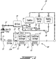
Fig. 2 is a schematic view of an exemplary oil cooling system of the aircraft engine ofFig. 1 ; -
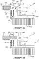
Fig. 3A is a schematic cross-sectional view of an exemplary bypass valve of the oil cooling system ofFig. 2 shown in an open configuration; -
Fig. 3B is a schematic cross-sectional view of the bypass valve ofFig. 3A shown in a closed configuration; and -
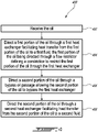
Fig. 4 is a flow chart illustrating a method of cooling oil of an aircraft engine. - The following disclosure describes oil cooling systems, bypass valves and associated methods of cooling oil of aircraft engines. In some embodiments, the systems and methods described herein may provide an oil cooling approach that is at least partially adaptive to cooling needs in a relatively simple, compact and cost-effective manner. In some embodiments, the systems and methods described herein may facilitate ability to apportion the amount of heat rejection from the oil to air, and from the oil to fuel based on operating conditions. In some embodiments, the ability to control cooling of the oil may be performed in a relatively passive manner.
- The terms "engaged" and "connected" may include both direct engagement or connection (in which two elements contact each other) and indirect engagement or connection (in which at least one additional element is located between the two elements).
- The term "substantially" as used herein may be applied to modify any quantitative representation which could permissibly vary without resulting in a change in the basic function to which it is related.
- Aspects of various embodiments are described through reference to the drawings.
-
Fig. 1 illustrates an aircraft engine depicted as agas turbine engine 10 of a type preferably provided for use in subsonic flight, generally comprising in serial flow communication afan 12 through which ambient air is propelled, acompressor section 14 for pressurizing the air, acombustor 16 in which the compressed air is mixed with fuel and ignited for generating an annular stream of hot combustion gases, and aturbine section 18 for extracting energy from the combustion gases. More specifically, thegas turbine engine 10 has a core gas path including anintake 19 for receiving air. Thecompressor section 14 has at least onecompressor 20 extending across the core gas path and theturbine section 18 has at least oneturbine 22 extending across the core gas path, with the at least onecompressor 20 and the at least oneturbine 22 being rotatable with ashaft 24 rotatably supported within thegas turbine engine 10 bybearings 26. Anoil system 28 is provided for circulating oil to thebearings 26 and back to anoil tank 30. Theoil system 28 may service one or more lubrication loads such as bearings and/or gears that require lubrication and/or cooling. It will be appreciated that the principles of the disclosure may apply to any aircraft engines, such as internal combustion engines (e.g., piston engine, rotary engine), any type of gas turbine engines, (e.g., turbofan, turboshaft, and turboprop), and auxiliary power units. - In the embodiment shown, the
gas turbine engine 10 has aoil cooling system 40 that is used to exchange heat between different fluids for proper operation of thegas turbine engine 10. In the present case, theoil cooling system 40 includes afirst heat exchanger 41, which may be referred to as a air-cooled oil cooler (ACOC), which is used to transfer heat from the oil to an environment E outside thegas turbine engine 10 via a bypass airflow flowing in an annular bypass duct of thegas turbine engine 10. As shown inFig. 3A , thefirst heat exchanger 41 includes anoil conduit 41A and fins 41B. The heat from the oil may be transferred to thefins 41B by conduction and from thefins 41B to the environment E by convection. Theoil cooling system 40 may further include asecond heat exchanger 42, which may be referred to as a fuel-oil heat exchanger (FOHE), used for transferring heat from the oil of theoil system 28 to fuel flowing from afuel tank 31, or any other fuel source, to thecombustor 16 of thegas turbine engine 10 for combustion. Pre-heating the fuel as such may increase efficiency of the combustion of the fuel and may cool down the oil that heats up while lubricating thebearings 26 or other lubrication load(s). - Referring to
Fig. 2 , theoil system 28 and theoil cooling system 40 are shown in greater detail. Theoil system 28 includes anoil pump 32 that drives an oil flow F1 within anoil conduit 33 from theoil tank 30. The oil flow F1 then exchanges heat with an airflow F2 through thefirst heat exchanger 41, and then exchanges heat with a fuel flow F3 through thesecond heat exchanger 42. The oil flow F1 is then distributed between different components (lubrication load(s)) in need of oil. In the present embodiment, the oil flow F1 is injected into bearing cavities and a gearbox. Used oil is then scavenged, and scavenge pump(s) 34 drive a scavenge oil flow F4 from scavenge outlets of the bearing cavities and the gearbox back to theoil tank 30 where the oil may be directed back to theoil pump 32 and recirculated. A de-oiler and/or de-aerator may be used to remove air from the scavenge oil flow F4. - The
first heat exchanger 41 may be used to transfer heat from the oil flow F1 to the airflow F2. This may decrease a temperature of the oil flow F1. Then, the oil flow F1 may flow through thesecond heat exchanger 42 where it transfers additional heat to the fuel in order to cool the oil further. However, in some operating conditions of thegas turbine engine 10, for instance, when thegas turbine engine 10 is operating in cold operating conditions, heat may be transferred from the oil to the fuel to heat the fuel to about 32 Fahrenheit (0°C) or higher. In some operating conditions, and more specifically when thegas turbine engine 10 is still warming up, the oil may not need to be cooled down with the air flow F2 before being directed through thesecond heat exchanger 42. Hence, it may be desired to direct at least some of the oil flow F1 (e.g., see flow F5) around thefirst heat exchanger 41 such that some of the oil flow F1 bypasses thefirst heat exchanger 41. Bypassing thefirst heat exchanger 41 may allow the oil to be at a higher temperature when it is injected in thesecond heat exchanger 42. Hence, more heat from the oil may be available to transfer to the fuel flow F3 when the first heat exchanger is bypassed. - Hence, a bypass 35 (i.e., bypass oil passage) may be connected to the
oil conduit 33 at two connection points being respectively upstream and downstream of thefirst heat exchanger 41. In other words, thebypass 35 has abypass inlet 35A fluidly connected to theoil conduit 33 upstream of thefirst heat exchanger 41 and abypass outlet 35B fluidly connected to theoil conduit 33 downstream of thefirst heat exchanger 41 and upstream of thesecond heat exchanger 42. Forexample oil conduit 33 may have an upstream portion (i.e., first conduit) fluidly connected to an inlet of thefirst heat exchanger 41 and supply thefirst heat exchanger 41 with some of the oil from oil flow F1, andoil conduit 33 may have a downstream portion (i.e., second conduit) fluidly connected to an outlet of thefirst heat exchanger 41 and receive the oil that has been directed through thefirst heat exchanger 41. Thebypass 35 may conduct a bypass oil flow F5 that corresponds to a portion of the oil flow F1 that bypasses thefirst heat exchanger 41. Abypass valve 36 may be fluidly connected to thebypass 35 and may be operable to control the flow of oil throughbypass 35. Thebypass valve 36 may be configurable between an open configuration and a closed configuration to selectively open or close thebypass 35. Thebypass valve 36 may be in the open configuration during relatively cold operating conditions of thegas turbine engine 10 to preserve heat from the oil to be preferably transferred to the fuel instead of the air. - However, in some embodiments, a pressure differential is provided along the
bypass 35 such that even when thebypass valve 36 is in the open configuration, some oil of the oil flow F1 may flow through thefirst heat exchanger 41. In some cases, it may be desirable to increase the bypass flow F5 to increase a temperature of the oil that is being directed through thesecond heat exchanger 42. One solution may be to increase a dimension (e.g., diameter) of thebypass 35 to reduce the resistance to flow throughbypass 35. However, doing so may require abigger bypass 35 and abigger bypass valve 36, which may add weight and size to the system. - In the embodiment shown, a
flow restrictor 37 is used to promote the flow of oil through thebypass 35 instead of through thefirst heat exchanger 41 in some situations. In other words, theflow restrictor 37 may increase a resistance to the oil flow F1 across thefirst heat exchanger 41. The oil may naturally tend to use the path of least resistance and more oil may flow through thebypass 35 rather than across thefirst heat exchanger 41 in some situations. The flow restrictor 37 may define a constriction (i.e., narrowing or reduced cross-sectional area of the available flow passage). The flow restrictor 37 may include a single orifice or a plurality of orifices (referred hereinafter in the singular) sized (e.g., calibrated) to increase resistance to flow and provide desired flow conditions in some situations. In some embodiments, theflow restrictor 37 may include a perforated body. - The orifice may cause a decrease in flow-receiving area of the
oil conduit 33 such that more oil flows through thebypass 35. Moreover, when cold, the oil may be more viscous. This may further increase the flow resistance of the oil across theflow restrictor 37. When the oil warms up and when thegas turbine engine 10 is in a cruise operating condition for example, the oil may be less viscous and the oil may flow through theflow restrictor 37 more easily with less resistance than when the oil is cold. The orifice of theflow restrictor 37 may be sized such that it discourages the oil from flowing through thefirst heat exchanger 41 when the oil is cold and such that it may not increase substantially a pressure differential across theflow restrictor 37 when the oil is at its nominal temperature. The nominal temperature refers to the temperature of the oil when theengine 10 is in a cruise operating condition for example. - In the depicted embodiment, the
flow restrictor 37 is in fluid flow communication with theoil conduit 33. The flow restrictor 37 may be located outside thebypass 35. The flow restrictor 37 may be located downstream of thebypass inlet 35A relative to the oil flow F1 in theoil conduit 33, and upstream of thebypass outlet 35B. The flow restrictor 37 may be located upstream, downstream or inside of thefirst heat exchanger 41. InFig. 2 , theflow restrictor 37 is located between thebypass inlet 35A and thefirst heat exchanger 41. An alternate position is shown with dashed lines and shows the flow restrictor 37' between thefirst heat exchanger 41 and thebypass outlet 35B. - In use, when the
bypass valve 36 is in the open configuration and allows the bypass flow F5 to flow in thebypass 35, an increased mass flow rate of oil may flow in thebypass 35 instead of through thefirst heat exchanger 41 compared to a configuration lacking theflow restrictor 37. Hence, a temperature of the oil in theoil conduit 33 at an intersection with thebypass outlet 35B may, in some situations, be greater thanks to theflow restrictor 37. This may result in more heat being available for transfer from the oil to the fuel via thesecond heat exchanger 42 since less heat from the oil is rejected via thefirst heat exchanger 41. - Referring now to
Figs. 3A and 3B , an alternate implementation of the flow restrictor is illustrated. In the embodiment shown, one ormore flow restrictors 137 may be incorporated into abypass valve 136. Thebypass valve 136 may have avalve body 136A and avalve member 136B that is movable relative to thevalve body 136A. Thevalve body 136A may define afirst oil passage 136C extending from afirst valve inlet 136D, which is fluidly connected to theoil conduit 33, to afirst valve outlet 136E fluidly connected to anoil conduit 41A of thefirst heat exchanger 41. Thevalve body 136A may have asecond oil passage 136F extending from asecond valve inlet 136G, which is fluidly connected to theoil conduit 41A of thefirst heat exchanger 41, to asecond valve outlet 136H, which is fluidly connected to theoil conduit 33 upstream of thesecond heat exchanger 42. - The
bypass valve 136 may include abypass 135 that connects thefirst oil passage 136C to thesecond oil passage 136F. As shown, thebypass 135 may have abypass inlet 135A and abypass outlet 135B. Thebypass inlet 135A is fluidly connected to thefirst oil passage 136C downstream of thefirst valve inlet 136D relative to the oil flow F1 and upstream of thefirst valve inlet 136D. Thebypass outlet 135B may be fluidly connected to thesecond oil passage 136F downstream of thesecond valve inlet 136G and upstream of thesecond valve outlet 136H. - As shown in
Fig. 3B , thevalve member 136B may extend into thesecond oil passage 136F when thevalve member 136B obstructs thebypass 135. It will be appreciated that thevalve member 136B may be dimensioned such as to not excessively obstruct the oil flow through thesecond oil passage 136F. Thevalve member 136B may include a shank and a head of a greater diameter than the shank. The head may be sized to open and close thebypass 135. The head may abut a seat located proximate or inside thebypass 135 to block the oil from flowing through thebypass 135. In some cases, thevalve member 136B may be provided in the form of a gate that is movable transversally relative to thebypass 135, like a guillotine, to close thebypass 135. - The
valve member 136B may be movable relative to thevalve body 136A from a first position corresponding to the open configuration of thebypass valve 136 to a second position corresponding to the closed configuration of thebypass valve 136. Thevalve member 136B may also be movable to intermediate positions between the open and closed configurations. As shown inFig. 3A , thevalve member 136B may be outside thebypass 135 in the first position. As shown inFig. 3B , thevalve member 136B may be occluding thebypass 135 in the second position. InFig. 3A , a bypass flow F5 is allowed and a portion of the oil flow F1 bypasses thefirst heat exchanger 41 and flows from thefirst valve inlet 136D to thesecond valve outlet 136H without flowing in theoil conduit 41A of thefirst heat exchanger 41. InFig. 3B , thevalve member 136B blocks thebypass 135 and the oil flow F1 is forced to flow through thefirst heat exchanger 41 to transfer a portion of its heat to the air flow F2 (Fig. 2 ). - In the embodiment shown, the
flow restrictor 137 is disposed in thesecond oil passage 136F downstream of thesecond valve inlet 136G and upstream of thebypass outlet 135B. Alternatively, the flow restrictor 137' may be located in thefirst oil passage 136C downstream of thebypass inlet 135A and upstream of thefirst valve outlet 136E. The flow restrictor 137 may be disposed outside of thebypass 135. It will be appreciated that, in another embodiment, theflow restrictor 137 may be located in theoil conduit 41A of thefirst heat exchanger 41. - In the embodiment shown, the
flow restrictor 137 is anannular member 137A defining acentral passage 137B. The flow restrictor 137 may decrease a flow-receiving area of thesecond oil passage 136F (or of thefirst oil passage 136C) by any amount suitable to achieve the desired thermal management within theoil system 28. In some applications, theflow restrictor 137 may decrease a flow-receiving area of thesecond oil passage 136F (or of thefirst oil passage 136C) by at least 50% for example. In some applications, theflow restrictor 137 may decrease a flow-receiving area of thesecond oil passage 136F (or of thefirst oil passage 136C) by about 90% for example. In some applications, theflow restrictor 137 may decrease a flow-receiving area of thesecond oil passage 136F (or of thefirst oil passage 136C) by between 50% to 95% for example. - The orifice of the
flow restrictor 137 may have any suitable cross-sectional shape, such as circular, elliptical, rectangular and square for example. The orifice of theflow restrictor 137 may tapered to have a conical shape. The flow restrictor 137 may be devoid of any moving part. The flow restrictor 137 may alternatively be a plate/screen with one or more orifices therethrough. Various types of flow restrictors may be suitable. The flow restrictor 137 may be a separate piece (body) inserted in thevalve body 136A or in theoil conduit 41A of thefirst heat exchanger 41. For example, theflow restrictor 137 may be a perforated body that is installed inside of thevalve body 136A. Alternatively, theflow restrictor 137 may include a constriction defined by (e.g., integrally formed with, having a unitary construction with) the first or second oil passages of thevalve body 136A or by theoil conduit 41A of thefirst heat exchanger 41. - A dimension of the central passage or orifice (or sizing of a group of orifices) of the
flow restrictor 137 may be selected to significantly reduce oil flow through thefirst heat exchanger 41 specifically during cold day operation when oil viscosity and a small restriction adds significantly higher pressure differential, thereby forcing more oil through thebypass Fig. 2 ) through thefirst heat exchanger 41 and increase oil heat available to transfer to fuel. Use of theflow restrictor 137 may add little weight to the design without the need to increase bypass valve and valve body size or increase the pressure differential of thefirst heat exchanger 41 itself. - At very low temperatures the oil residing in the
first heat exchanger 41 may be relatively viscous. In order to decongeal this oil mass, a minimum amount of heat may be required while thebypass valve 36 is open. This minimum amount of heat available for decongealing the oil residing in thefirst heat exchanger 41 may be determined by the flow split between thefirst heat exchanger 41 and thebypass 35. The flow restrictor 137 may be designed based on an oil decongealing margin to passively control the heat rejection from the oil to the bypass air where basic geometry, form factor, aerodynamic concerns and/or the installed configuration typically do not facilitate such optimization. - Still referring to
Figs. 3A and 3B , thevalve member 136B may be engaged by an actuator, such as alinear actuator 138. Thevalve member 136B may be a movable part of an actuator. For example, thevalve member 136B may be part of a self-regulating thermostatic valve. Thelinear actuator 138 may be a wax actuator that expands and contracts as a function of temperature. That is, thelinear actuator 138 may not need to be actively control by a controller and may automatically expand and contract with the temperature of the oil. In the present case, thebypass valve 136 may be in the open configuration when a temperature of the oil flow is below a first temperature threshold and in the closed configuration when the temperature of the oil flow is above a second temperature threshold. In some embodiments, the first and second temperature thresholds may correspond to about 195 Fahrenheit. Thevalve member 136B may be moved from the second position depicted inFig. 3B where it blocks thebypass 135 to the first position depicted inFig. 3A where it is offset from thebypass 135 when the temperature is below 195 Fahrenheit for example. - It will be appreciated that, in an alternate embodiment, the
linear actuator 138 may be operatively connected to a controller that receives a signal from a sensor; the signal indicative of a temperature and/or a pressure of the oil. In such cases, the actuator may be a solenoid, a pneumatic actuator, a hydraulic actuator, or any other suitable actuator. The controller may therefore control the opening and closing of thebypass 135 as a function of the temperature of the oil. - Referring now to
Fig. 4 , a flow chart illustrates amethod 400 for cooling oil of theoil system 28. Aspects ofmethod 400 may be combined with other aspects or actions disclosed herein. Aspects ofsystem 28 may be incorporated intomethod 400. In various embodiments, themethod 400 may include receiving the oil at 402, directing a first portion of the oil through thefirst heat exchanger 41 for facilitating heat transfer from the first portion of the oil to a first fluid, the first portion of the oil being directed through theflow restrictor first heat exchanger 41 at 404; directing a second portion of the oil through thebypass oil passage 35 allowing the second portion of the oil to bypass thefirst heat exchanger 41 at 406; and directing the second portion of the oil through thesecond heat exchanger 42 facilitating heat transfer from the second portion of the oil to a second fluid at 408. - The first fluid may be air and the second fluid may be fuel. However, it is understood that in some embodiments, the first fluid may be fuel and the second fluid may be air. In some embodiments, both fluids may be of the same type (e.g., both air or both fuel). Other fluids may also be used to cool the oil. The
method 400 may include directing the first portion of the oil through thesecond heat exchanger 42. The flow restrictor 37, 137 may be disposed upstream of thefirst heat exchanger 41 relative to a flow of the first portion of the oil through thefirst heat exchanger 41. The flow restrictor 37, 137 may be disposed downstream of thefirst heat exchanger 41 relative to the flow of the first portion of the oil through thefirst heat exchanger 41. - The embodiments described in this document provide non-limiting examples of possible implementations of the present technology. Upon review of the present disclosure, a person of ordinary skill in the art will recognize that changes may be made to the embodiments described herein without departing from the scope of the present technology. Yet further modifications could be implemented by a person of ordinary skill in the art in view of the present disclosure, which modifications would be within the scope of the present technology.
Claims (15)
- An oil cooling system (40) for an aircraft engine (10), the oil cooling system (40) comprising:a first oil conduit (33);a heat exchanger (41) having an inlet and an outlet, the inlet being in fluid communication with the first oil conduit (33) to receive a first oil flow (F1) from the first oil conduit (33), the heat exchanger (41) facilitating heat transfer from the first oil flow to a first fluid (F2);a flow restrictor (37; 137; 137') defining a constriction and being operatively disposed to restrict the first oil flow (F1) through the heat exchanger (41);a second oil conduit in fluid communication with the outlet of the heat exchanger (41) to receive the first oil flow (F1) from the heat exchanger (41); anda bypass (35; 135) providing fluid communication between the first oil conduit (33) and the second oil conduit to allow a second oil flow (F5) received from the first oil conduit (33) to bypass the heat exchanger (41) and flow to the second oil conduit.
- The oil cooling system (40) as defined in claim 1, wherein:the heat exchanger (41) is a first heat exchanger (41) facilitating heat transfer from the first oil flow (F1) to air (F2); andthe oil cooling system (40) includes a second heat exchanger (42) downstream of the first heat exchanger (41) to facilitate heat transfer from oil received from the second oil conduit to fuel (F3).
- The oil cooling system (40) as defined in claim 1 or 2, comprising a valve (36; 136) configurable between an open configuration and a closed configuration to control the second oil flow (F5) through the bypass (35; 135), wherein the valve (36; 136) is optionally a thermostatic valve.
- The oil cooling system (40) as defined in claim 3, wherein:the valve (36; 136) includes a valve body (136A) defining a passage (136C) establishing fluid communication between the first oil conduit (33) and the inlet of the heat exchanger (41); andthe flow restrictor (37; 137') is disposed inside the passage (136C).
- The oil cooling system (40) as defined in claim 3, wherein:the valve (36; 136) includes a valve body (136A) defining a passage (136F) establishing fluid communication between the outlet of the heat exchanger (41) and the second oil conduit; andthe flow restrictor (37; 137) is disposed inside the passage (136F).
- The oil cooling system (40) of any preceding claim, wherein:the flow restrictor (37; 137; 137') is disposed inside a or the passage (136C; 136F); andthe flow restrictor (37; 137; 137') defines a reduction of at least 50% in flow-receiving cross-sectional area relative to the passage (136C; 136F).
- The oil cooling system (40) as defined in claim 4, 5, or 6, wherein the flow restrictor (36; 137; 137') includes a perforated body installed inside the passage (136C; 136F).
- A bypass valve (36; 136) for an oil cooling system (40) of an aircraft engine (10), the bypass valve (36; 136) comprising:a valve body (136A) defining:a first oil passage (136C) extending from a first inlet (136D) to a first outlet (136E);a second oil passage (136F) extending from a second inlet (136G) to a second outlet (136H); anda bypass oil passage (35; 135) fluidly connecting the first oil passage (136C) to the second oil passage (136F);a valve member (136B) operable to control oil flow through the bypass oil passage (35; 135); anda flow restrictor (37; 137; 137') defining a constriction and disposed inside the valve body (136A) either:inside the first oil passage (136C) downstream of the bypass oil passage (135) relative to the first inlet (136D) and the first outlet (136E); orinside the second oil passage (136F) upstream of the bypass oil passage (135) relative to the second inlet (136G) and the second outlet (136H).
- The bypass valve (36; 136) as defined in claim 8, wherein the flow restrictor (37; 137; 137') includes a perforated body installed inside the first or second oil passages (136C, 136F).
- The bypass valve (36; 136) as defined in claim 8 or 9, wherein the flow restrictor (37; 137) is disposed inside the second oil passage (136F).
- The bypass valve (36; 136) as defined in claim 8 or 9, wherein the flow restrictor (37; 137') is disposed inside the first oil passage (136C).
- The bypass valve (36; 136) as defined in any of claims 8 to 11, wherein the valve member (136B) is part of a self-regulating thermostatic valve.
- A method (400) of cooling oil of an aircraft engine (10), the method (400) comprising:(402) receiving the oil (F1);(404) directing a first portion of the oil through a first heat exchanger (41) facilitating heat transfer from the first portion of the oil (F1) to a first fluid (F2), the first portion of the oil (F1) being directed through a flow restrictor (37; 137; 137') defining a constriction to restrict the first portion of the oil (F1) through the first heat exchanger (41);(406) directing a second portion (F5) of the oil (F1) through a bypass oil passage (35; 135) allowing the second portion (F5) of the oil (F1) to bypass the first heat exchanger (41); and(408) directing the second portion (F5) of the oil (F1) through a second heat exchanger (42) facilitating heat transfer from the second portion of the oil (F5) to a second fluid (F3).
- The method (400) as defined in claim 13, wherein:the first fluid (F2) is air and the second fluid (F3) is fuel; and/orthe method (400) further comprises directing the first portion of the oil (F1) through the second heat exchanger (42).
- The method (400) as defined in claim 13 or 14, wherein the flow restrictor (37; 137; 137') is disposed either upstream or downstream of the first heat exchanger (41) relative to a flow of the first portion of the oil (F1) through the first heat exchanger (41).
Applications Claiming Priority (1)
| Application Number | Priority Date | Filing Date | Title |
|---|---|---|---|
| US17/350,250 US11591964B2 (en) | 2021-06-17 | 2021-06-17 | Oil cooling system for aircraft engine |
Publications (2)
| Publication Number | Publication Date |
|---|---|
| EP4105465A2 true EP4105465A2 (en) | 2022-12-21 |
| EP4105465A3 EP4105465A3 (en) | 2023-05-03 |
Family
ID=82115811
Family Applications (1)
| Application Number | Title | Priority Date | Filing Date |
|---|---|---|---|
| EP22179738.4A Pending EP4105465A3 (en) | 2021-06-17 | 2022-06-17 | Oil cooling system for aircraft engine |
Country Status (3)
| Country | Link |
|---|---|
| US (1) | US11591964B2 (en) |
| EP (1) | EP4105465A3 (en) |
| CA (1) | CA3163441A1 (en) |
Families Citing this family (15)
| Publication number | Priority date | Publication date | Assignee | Title |
|---|---|---|---|---|
| GB202214143D0 (en) | 2022-09-28 | 2022-11-09 | Rolls Royce Plc | Gas turbine engine with an improved thermal management system |
| GB202214148D0 (en) | 2022-09-28 | 2022-11-09 | Rolls Royce Plc | Gas turbine engine with improved heat management |
| GB202214153D0 (en) | 2022-09-28 | 2022-11-09 | Rolls Royce Plc | Modulated heat management for geared gas turbine engines |
| GB202214146D0 (en) * | 2022-09-28 | 2022-11-09 | Rolls Royce Plc | Method of operating a gas turbine engine |
| GB202219390D0 (en) * | 2022-12-21 | 2023-02-01 | Rolls Royce Plc | Gas turbine operation |
| GB202219391D0 (en) | 2022-12-21 | 2023-02-01 | Rolls Royce Plc | Fuel oil heat exchange |
| US12129043B1 (en) * | 2023-08-28 | 2024-10-29 | Pratt & Whitney Canada Corp. | Aircraft heat exchanger bypass flow control with electric motor |
| GB202319127D0 (en) * | 2023-12-14 | 2024-01-31 | Rolls Royce Plc | Heat exchange bypass |
| GB202319150D0 (en) * | 2023-12-14 | 2024-01-31 | Rolls Royce Plc | Fueldraulic heat management system |
| GB202319120D0 (en) * | 2023-12-14 | 2024-01-31 | Rolls Royce Plc | Gas turbine engine heat exchange |
| GB202319125D0 (en) | 2023-12-14 | 2024-01-31 | Rolls Royce Plc | Operating a gas turbine engine |
| GB202319159D0 (en) | 2023-12-14 | 2024-01-31 | Rolls Royce Plc | Fueldraulic actuation |
| GB202319124D0 (en) * | 2023-12-14 | 2024-01-31 | Rolls Royce Plc | Heat exchange system |
| US20250334352A1 (en) * | 2024-04-29 | 2025-10-30 | Pratt & Whitney Canada Corp. | Heat exchanger having a mixing chamber with louvers |
| US20260062135A1 (en) * | 2024-09-03 | 2026-03-05 | Honeywell International Inc. | Vehicle thermal management system |
Family Cites Families (16)
| Publication number | Priority date | Publication date | Assignee | Title |
|---|---|---|---|---|
| US3486582A (en) * | 1967-10-30 | 1969-12-30 | Caterpillar Tractor Co | Lubrication system for a gas turbine engine |
| GB2111128B (en) | 1981-12-10 | 1984-10-17 | Rolls Royce | Fuel/oil heat exchange system for a gas turbine engine |
| GB9008140D0 (en) * | 1990-04-10 | 1990-06-06 | Rolls Royce Plc | An apparatus for and method of filtering a fluid |
| US6128969A (en) * | 1998-05-12 | 2000-10-10 | Board Of Trustees Of The University Of Illinois | Hybrid gear drive |
| US6422020B1 (en) | 2000-03-13 | 2002-07-23 | Allison Advanced Development Company | Cast heat exchanger system for gas turbine |
| US8997449B2 (en) * | 2008-12-22 | 2015-04-07 | Pratt & Whitney Canada Corp. | Flow restrictor for lubrication line |
| US7997062B2 (en) * | 2009-01-29 | 2011-08-16 | Pratt & Whitney Canada Corp. | Dual channel regulated fuel-oil heat exchanger |
| FR2979671B1 (en) * | 2011-09-07 | 2017-02-10 | Snecma | OIL AND FUEL CIRCUITS IN A TURBOMACHINE |
| US9097169B2 (en) | 2011-10-11 | 2015-08-04 | Pratt & Whitney Canada Corp. | Gas turbine engine heat management system |
| FR2991384B1 (en) | 2012-06-01 | 2014-06-20 | Snecma | FLUID CIRCUIT IN A TURBOMACHINE |
| FR3002591B1 (en) | 2013-02-27 | 2015-04-03 | Snecma | METHOD AND DEVICE FOR CONTROLLING OIL COOLING OF A TURBOMACHINE |
| EP3094845B1 (en) | 2014-01-15 | 2020-04-29 | United Technologies Corporation | Cooling systems for gas turbine engines |
| KR102103337B1 (en) * | 2016-04-21 | 2020-04-23 | 쯔지앙 산후아 오토모티브 컴포넌츠 컴퍼니 리미티드 | Thermostat and temperature control system |
| US10900422B2 (en) | 2017-01-31 | 2021-01-26 | Pratt & Whitney Canada Corp. | Heat exchanger system for aircraft and associated method of operation |
| EP3418505B1 (en) * | 2017-06-23 | 2022-04-13 | HS Marston Aerospace Limited | Heated lubrication circuit |
| JP6830049B2 (en) | 2017-08-31 | 2021-02-17 | 三菱パワー株式会社 | Control device and gas turbine combined cycle power generation system with it, program, and control method of gas turbine combined cycle power generation system |
-
2021
- 2021-06-17 US US17/350,250 patent/US11591964B2/en active Active
-
2022
- 2022-06-16 CA CA3163441A patent/CA3163441A1/en active Pending
- 2022-06-17 EP EP22179738.4A patent/EP4105465A3/en active Pending
Also Published As
| Publication number | Publication date |
|---|---|
| US20220403779A1 (en) | 2022-12-22 |
| US11591964B2 (en) | 2023-02-28 |
| CA3163441A1 (en) | 2022-12-17 |
| EP4105465A3 (en) | 2023-05-03 |
Similar Documents
| Publication | Publication Date | Title |
|---|---|---|
| US11591964B2 (en) | Oil cooling system for aircraft engine | |
| US9739198B2 (en) | Oil and fuel circuits in a turbine engine | |
| EP1329617B1 (en) | Fluid flow system for a gas turbine engine | |
| CA2690780C (en) | Dual channel regulated fuel-oil heat exchanger | |
| US20090097972A1 (en) | Gas Turbine Engine Systems and Related Methods Involving Heat Exchange | |
| EP2587024B1 (en) | Gas turbine engine thermal management system | |
| US10900422B2 (en) | Heat exchanger system for aircraft and associated method of operation | |
| US9097169B2 (en) | Gas turbine engine heat management system | |
| EP2803845A1 (en) | Heat exchange arrangement | |
| US11982234B1 (en) | Heat exchanger with bypass valve and thermal fuse | |
| US10151242B2 (en) | Oil cooling system | |
| US10823074B2 (en) | Recirculation of fluid through a turbomachine centrifugal pump | |
| EP0563180A1 (en) | Heat exchange apparatus for gas turbine fluids. | |
| JP2014034975A (en) | Gas turbine heat exchanger operating method and device | |
| CN106917684A (en) | Heat management system | |
| US20230068644A1 (en) | Heat exchange system using compressor air for fuel pre-heating | |
| EP4095371B1 (en) | Heat exchange system for aircraft engine | |
| CN116802390A (en) | Heat exchanger installed in turbine engine cavity | |
| EP4477861A1 (en) | Gas turbine engine with air/oil cooler having an airflow control baffle | |
| US10823068B2 (en) | Heat exchanger device for an aircraft engine | |
| US12203381B2 (en) | Aircraft engine fluid system with bypass valve |
Legal Events
| Date | Code | Title | Description |
|---|---|---|---|
| PUAI | Public reference made under article 153(3) epc to a published international application that has entered the european phase |
Free format text: ORIGINAL CODE: 0009012 |
|
| STAA | Information on the status of an ep patent application or granted ep patent |
Free format text: STATUS: THE APPLICATION HAS BEEN PUBLISHED |
|
| AK | Designated contracting states |
Kind code of ref document: A2 Designated state(s): AL AT BE BG CH CY CZ DE DK EE ES FI FR GB GR HR HU IE IS IT LI LT LU LV MC MK MT NL NO PL PT RO RS SE SI SK SM TR |
|
| PUAL | Search report despatched |
Free format text: ORIGINAL CODE: 0009013 |
|
| AK | Designated contracting states |
Kind code of ref document: A3 Designated state(s): AL AT BE BG CH CY CZ DE DK EE ES FI FR GB GR HR HU IE IS IT LI LT LU LV MC MK MT NL NO PL PT RO RS SE SI SK SM TR |
|
| RIC1 | Information provided on ipc code assigned before grant |
Ipc: F02C 7/14 20060101AFI20230328BHEP |
|
| STAA | Information on the status of an ep patent application or granted ep patent |
Free format text: STATUS: REQUEST FOR EXAMINATION WAS MADE |
|
| 17P | Request for examination filed |
Effective date: 20231102 |
|
| RBV | Designated contracting states (corrected) |
Designated state(s): AL AT BE BG CH CY CZ DE DK EE ES FI FR GB GR HR HU IE IS IT LI LT LU LV MC MK MT NL NO PL PT RO RS SE SI SK SM TR |
|
| STAA | Information on the status of an ep patent application or granted ep patent |
Free format text: STATUS: EXAMINATION IS IN PROGRESS |
|
| 17Q | First examination report despatched |
Effective date: 20250409 |