EP4105345A1 - Cylinder head, cylinder block, internal combustion engine, and method for manufacturing cylinder head - Google Patents
Cylinder head, cylinder block, internal combustion engine, and method for manufacturing cylinder head Download PDFInfo
- Publication number
- EP4105345A1 EP4105345A1 EP21787810.7A EP21787810A EP4105345A1 EP 4105345 A1 EP4105345 A1 EP 4105345A1 EP 21787810 A EP21787810 A EP 21787810A EP 4105345 A1 EP4105345 A1 EP 4105345A1
- Authority
- EP
- European Patent Office
- Prior art keywords
- region
- cylinder head
- fluid circulation
- circulation port
- cylinder block
- Prior art date
- Legal status (The legal status is an assumption and is not a legal conclusion. Google has not performed a legal analysis and makes no representation as to the accuracy of the status listed.)
- Pending
Links
Images



Classifications
-
- F—MECHANICAL ENGINEERING; LIGHTING; HEATING; WEAPONS; BLASTING
- F02—COMBUSTION ENGINES; HOT-GAS OR COMBUSTION-PRODUCT ENGINE PLANTS
- F02F—CYLINDERS, PISTONS OR CASINGS, FOR COMBUSTION ENGINES; ARRANGEMENTS OF SEALINGS IN COMBUSTION ENGINES
- F02F1/00—Cylinders; Cylinder heads
- F02F1/24—Cylinder heads
- F02F1/26—Cylinder heads having cooling means
- F02F1/36—Cylinder heads having cooling means for liquid cooling
- F02F1/40—Cylinder heads having cooling means for liquid cooling cylinder heads with means for directing, guiding, or distributing liquid stream
-
- F—MECHANICAL ENGINEERING; LIGHTING; HEATING; WEAPONS; BLASTING
- F02—COMBUSTION ENGINES; HOT-GAS OR COMBUSTION-PRODUCT ENGINE PLANTS
- F02F—CYLINDERS, PISTONS OR CASINGS, FOR COMBUSTION ENGINES; ARRANGEMENTS OF SEALINGS IN COMBUSTION ENGINES
- F02F1/00—Cylinders; Cylinder heads
- F02F1/24—Cylinder heads
-
- C—CHEMISTRY; METALLURGY
- C21—METALLURGY OF IRON
- C21D—MODIFYING THE PHYSICAL STRUCTURE OF FERROUS METALS; GENERAL DEVICES FOR HEAT TREATMENT OF FERROUS OR NON-FERROUS METALS OR ALLOYS; MAKING METAL MALLEABLE, e.g. BY DECARBURISATION OR TEMPERING
- C21D1/00—General methods or devices for heat treatment, e.g. annealing, hardening, quenching or tempering
- C21D1/06—Surface hardening
- C21D1/09—Surface hardening by direct application of electrical or wave energy; by particle radiation
-
- C—CHEMISTRY; METALLURGY
- C21—METALLURGY OF IRON
- C21D—MODIFYING THE PHYSICAL STRUCTURE OF FERROUS METALS; GENERAL DEVICES FOR HEAT TREATMENT OF FERROUS OR NON-FERROUS METALS OR ALLOYS; MAKING METAL MALLEABLE, e.g. BY DECARBURISATION OR TEMPERING
- C21D5/00—Heat treatments of cast-iron
-
- C—CHEMISTRY; METALLURGY
- C21—METALLURGY OF IRON
- C21D—MODIFYING THE PHYSICAL STRUCTURE OF FERROUS METALS; GENERAL DEVICES FOR HEAT TREATMENT OF FERROUS OR NON-FERROUS METALS OR ALLOYS; MAKING METAL MALLEABLE, e.g. BY DECARBURISATION OR TEMPERING
- C21D9/00—Heat treatment, e.g. annealing, hardening, quenching or tempering, adapted for particular articles; Furnaces therefor
- C21D9/0068—Heat treatment, e.g. annealing, hardening, quenching or tempering, adapted for particular articles; Furnaces therefor for particular articles not mentioned below
-
- F—MECHANICAL ENGINEERING; LIGHTING; HEATING; WEAPONS; BLASTING
- F02—COMBUSTION ENGINES; HOT-GAS OR COMBUSTION-PRODUCT ENGINE PLANTS
- F02F—CYLINDERS, PISTONS OR CASINGS, FOR COMBUSTION ENGINES; ARRANGEMENTS OF SEALINGS IN COMBUSTION ENGINES
- F02F11/00—Arrangements of sealings in combustion engines
- F02F11/002—Arrangements of sealings in combustion engines involving cylinder heads
-
- C—CHEMISTRY; METALLURGY
- C21—METALLURGY OF IRON
- C21D—MODIFYING THE PHYSICAL STRUCTURE OF FERROUS METALS; GENERAL DEVICES FOR HEAT TREATMENT OF FERROUS OR NON-FERROUS METALS OR ALLOYS; MAKING METAL MALLEABLE, e.g. BY DECARBURISATION OR TEMPERING
- C21D2221/00—Treating localised areas of an article
-
- C—CHEMISTRY; METALLURGY
- C21—METALLURGY OF IRON
- C21D—MODIFYING THE PHYSICAL STRUCTURE OF FERROUS METALS; GENERAL DEVICES FOR HEAT TREATMENT OF FERROUS OR NON-FERROUS METALS OR ALLOYS; MAKING METAL MALLEABLE, e.g. BY DECARBURISATION OR TEMPERING
- C21D2221/00—Treating localised areas of an article
- C21D2221/01—End parts (e.g. leading, trailing end)
-
- C—CHEMISTRY; METALLURGY
- C22—METALLURGY; FERROUS OR NON-FERROUS ALLOYS; TREATMENT OF ALLOYS OR NON-FERROUS METALS
- C22C—ALLOYS
- C22C37/00—Cast-iron alloys
-
- F—MECHANICAL ENGINEERING; LIGHTING; HEATING; WEAPONS; BLASTING
- F02—COMBUSTION ENGINES; HOT-GAS OR COMBUSTION-PRODUCT ENGINE PLANTS
- F02F—CYLINDERS, PISTONS OR CASINGS, FOR COMBUSTION ENGINES; ARRANGEMENTS OF SEALINGS IN COMBUSTION ENGINES
- F02F2200/00—Manufacturing
Definitions
- the present invention relates to a cylinder head, a cylinder block, an internal combustion engine, and a method for manufacturing a cylinder head.
- a cylinder head is attached to a cylinder block.
- the cylinder head is fastened to the cylinder block with a fastening member such as a bolt and is attached to the cylinder block while the surfaces of the cylinder head and the cylinder block are in contact with each other via a gasket, for example.
- PTL 1 describes that laser quenching is performed on a cylinder liner sliding surface.
- the cylinder head and the cylinder block seal the combustion gas in the contact surface thereof.
- the in-cylinder pressure tends to increase due to the influence of downsizing and the like.
- the sealing defect may occur when the in-cylinder pressure increases.
- the sealing property has been improved by increasing the axial force of the fastening member, increasing the number of fastening members, improving the structure of the gasket, and the like.
- the improvement of the sealing property is insufficient, thereby some parts of the contact surface between the cylinder head and the cylinder head gasket and the contact surface between the cylinder block and the cylinder head gasket cause relative slippage, the contact surface is worn, and then the combustion gas may leak.
- the sealing property may not be appropriately improved at a location away from the fastening member.
- the present disclosure has been made to solve the above-mentioned problems, and an object of the present invention is to provide a cylinder head, a cylinder block, an internal combustion engine, and a method for manufacturing a cylinder head capable of suppressing leakage of combustion gas from a contact surface.
- a cylinder head according to the present disclosure is a cylinder head that is to be attached to a cylinder block, in which a surface of the cylinder head on a side to be attached to the cylinder block includes a first region and a second region having hardness higher than that of the first region.
- a cylinder block according to the present disclosure is a cylinder block that is to be attached to a cylinder head, in which a surface of the cylinder block on a side to be attached to the cylinder head includes a first region and a second region having hardness higher than that of the first region.
- an internal combustion engine includes one or more cylinder heads and a cylinder block.
- a method for manufacturing a cylinder head is a method for manufacturing a cylinder head that is to be attached to a cylinder block, the method includes forming a first region where a curing treatment is not performed and a second region, where the curing treatment is performed and hardness is higher than that of the first region, by performing the curing treatment on a part of a surface of the cylinder head on a side to be attached to the cylinder block.
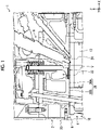
- Fig. 1 is a schematic partial cross-sectional view of an internal combustion engine according to the present embodiment.
- the internal combustion engine 1 according to the present embodiment includes a cylinder head assembly 2, a cylinder block assembly 4, and a gasket 6.
- the internal combustion engine 1 is an engine powered by the combustion of fuel, and examples thereof include a diesel engine, a gasoline engine, and a gas engine.
- the internal combustion engine 1 can be used for anything and may be an engine, for example, for a vehicle, a ship, a generator, an industrial use, or an engine for a fixed facility.
- the cylinder block assembly 4 includes a cylinder block 10 and a piston P.
- a material of the cylinder block 10 is cast iron and may be, for example, FC250 defined by JIS G5501:1995, FCD400 defined by JIS G5502:2001, FCD450, or the like. However, the material of the cylinder block 10 is not limited to the above-described materials.
- An opening 12 is formed in the cylinder block 10. The opening 12 opens to a surface 14 of the cylinder block 10. The opening 12 is provided with the piston P that is connected to a crankshaft (not shown). The piston P slides inside the opening 12 in an extending direction of the opening 12.
- a cylinder liner which is a cylindrical member, may be inserted into the opening 12.
- a direction Z the extending direction of the opening 12
- a direction orthogonal to the direction Z is defined as a direction X
- a direction orthogonal to the direction Z and the direction X is defined as a direction Y.
- the internal combustion engine 1 has multiple cylinders, and a plurality of openings 12 are provided in the direction Y.
- the internal combustion engine 1 is formed with four openings 12 in the direction Y, but the present disclosure is not limited to this.
- the number of openings 12 (number of cylinders) may be any number or an arrangement direction of the openings 12 may be any direction.
- a cylinder head assembly 2 includes the cylinder head 20, a valve V, and an ignition device N.
- the ignition device N is a device for igniting the combustion chamber.
- the ignition device N is a nozzle into which high-pressure fuel is injected in the present embodiment and can be called an ignition device because the high-pressure fuel injected from the nozzle spontaneously ignites.
- the ignition device N is not limited to the nozzle and may be, for example, a spark ignition device that ignites by discharging.
- the cylinder head 20 is attached to the cylinder block 10 with a surface 26 in contact with the surface 14 of the cylinder block 10 via a gasket 6 by tightening with a fastening member (a bolt here) (not shown).
- the surface 26 of the cylinder head 20 is pressed against the surface 14 of the cylinder block 10.
- the gasket 6 is not an essential configuration, and the surface 26 of the cylinder head 20 and the surface 14 of the cylinder block 10 may be in direct contact with each other.
- the surface 26 of the cylinder head 20 includes a first portion 26A overlapping the opening 12 when viewed from the direction Z and a second portion 26B overlapping the surface 14 of the cylinder block 10 when viewed from the direction Z. Since the cylinder head 20 covers the opening 12 with the first portion 26A, it can be said that the first portion 26A is a portion exposed to combustion gas generated in the combustion chamber. Further, the second portion 26B is a portion that does not overlap the opening 12 and is pressed against the surface 14 of the cylinder block 10 and is not exposed to the combustion gas. It can be said that the second portion 26B is formed on an outer side in a radial direction with respect to the first portion 26A when the central axis along the direction Z of the first portion 26A is the center.
- the material of the cylinder head 20 is cast iron and may be, for example, FC250 defined in JIS G5501:1995 or FC300.
- the material of the cylinder head 20 is not limited to the above-described materials.
- the cylinder head 20 is formed with an opening such as an intake port 22 or an opening 24 for an ignition device.
- the opening such as the intake port 22 and the opening 24 for an ignition device is open in the first portion 26A on the surface 26.
- the intake port 22 is provided with a valve V for introducing air into the combustion chamber, and the opening 24 for an ignition device is provided with the ignition device N for injecting fuel into the combustion chamber.
- the cylinder head 20 may be formed with an exhaust port for discharging gas from the combustion chamber. In this case, the exhaust port also is open to the first portion 26A on the surface 26.
- the first portion 26A is a region on the surface 26 in which an opening communicating with the combustion chamber (here, the intake port 22, the opening 24 for an ignition device, or the like) is formed.
- an opening may be formed over a part or the entire of the first portion 26A, and the intake port 22, the opening 24 for an ignition device, or the like may communicate with the opening.
- the space surrounded by the opening of the first portion 26A, the piston P, and the opening 12 of the cylinder block 10 becomes the combustion chamber.
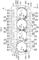
- Fig. 2 is a schematic view of a mating surface of the cylinder head with the cylinder block according to the present embodiment.
- a plurality of first portions 26A are formed along the direction Y in accordance with the openings 12 (see Fig. 3 ) of the cylinder block 10.
- the first portion 26A as the first portion 26A, the first portions 26A1, 26A2, 26A3, and 26A4 are arranged in the direction Y.
- fastening holes 30 and fluid circulation ports 32 are formed on the surface 26 of the cylinder head 20.
- the fastening holes 30 are holes (openings) into which the fastening members for fastening the cylinder head 20 and the cylinder block 10 are inserted, and a plurality of fastening holes 30 are formed on the surface 26.
- the fluid circulation port 32 is a hole through which a fluid circulates, and a plurality of fluid circulation ports 32 are formed on the surface 26.
- a fluid that is different from the combustion gas, which is generated by the combustion of the fuel inside the combustion chamber, circulates through the fluid circulation port 32. Any type can be used for the type of the fluid that circulates through the fluid circulation port 32, for example, the fluid may be cooling water for cooling the internal combustion engine 1, lubricant for lubricating the internal combustion engine 1, or the like.
- the fastening hole 30 is open to the second portion 26B on the surface 26.
- the fastening hole 30 is formed in the second portion 26B around the first portion 26A. More specifically, the plurality of fastening holes 30 are formed along a circumferential direction when the central axis along the direction Z of the first portion 26A is the center.
- the fastening hole 30Q is formed from the fastening hole 30A as the fastening hole 30.
- the fastening holes 30A, 30B, 30C, 30D, and 30E are formed so as to be arranged around the first portion 26A1 along the circumferential direction of the first portion 26A1.
- the fastening holes 30D, 30F, 30G, 30H, and 301 are formed so as to be arranged around the first portion 26A2 along the circumferential direction of the first portion 26A2.
- the fastening holes 30H, 30J, 30K, 30L, and 30M are formed so as to be arranged around the first portion 26A3 along the circumferential direction of the first portion 26A3.
- the fastening holes 30L, 30N, 30o, 30P, and 30Q are formed so as to be arranged around the first portion 26A4 along the circumferential direction of the first portion 26A4.
- Fig. 2 is an example, and the total number of fastening holes 30 formed in the cylinder head 20 or the number of fastening holes 30 around one first portion 26A may be any number.
- the fastening holes 30 around the first portion 26A are not arranged at equal intervals in the circumferential direction, in other words, a distance between the fastening holes 30 adjacent to each other in the circumferential direction is not constant.
- a distance between the fastening hole 30A and the fastening hole 30B, a distance between the fastening hole 30B and the fastening hole 30C, a distance between the fastening hole 30C and the fastening hole 30D, a distance between the fastening hole 30D and the fastening hole 30E, and a distance between the fastening hole 30E and the fastening hole 30A is different from the others.
- the distance between the fastening hole 30C and the fastening hole 30D is the longest.
- the fastening holes 30 around the first portion 26A may be arranged at equal intervals in the circumferential direction.
- the fluid circulation port 32 is open to the second portion 26B on the surface 26.
- the fluid circulation port 32Y is formed from the fluid circulation port 32A as the fluid circulation port 32.
- the fluid circulation port 32A to the fluid circulation port 32I are formed on the side opposite to the direction X from the center point P1 when the first portion 26A is viewed from the direction Z, that is, formed on an intake side, and the fluid circulation port 32A to the fluid circulation port 32I are arranged in this order in the direction Y.
- the fluid circulation port 32A is positioned on the side opposite to the direction Y with respect to the center point P1 of the first portion 26A1
- the fluid circulation port 32B is positioned on the side opposite to the direction X with respect to the center point P1 of the first portion 26A1.
- the fluid circulation port 32C is positioned on the direction Y side with respect to the center point P1 of the first portion 26A1 and on the side opposite to the direction Y with respect to the center point P1 of the first portion 26A2, and the fluid circulation port 32D is positioned on the side opposite to the direction X with respect to the center point P1 of the first portion 26A2.
- the fluid circulation port 32E is positioned on the direction Y side with respect to the center point P1 of the first portion 26A2 and on the side opposite to the direction Y with respect to the center point P1 of the first portion 26A3, and the fluid circulation port 32F is positioned on the side opposite to the direction X with respect to the center point P1 of the first portion 26A3.
- the fluid circulation port 32G is positioned on the direction Y side with respect to the center point P1 of the first portion 26A3 and on the side opposite to the direction Y with respect to the center point P1 of the first portion 26A4, the fluid circulation port 32H is positioned on the side opposite to the direction X with respect to the center point P1 of the first portion 26A4, the fluid circulation port 321 is positioned in the direction Y with respect to the center point P1 of the first portion 26A4.
- the number of fluid circulation ports 32 and the position thereof are not limited to this and may be any number and position.
- the fluid circulation port 32J to the fluid circulation port 32Y are formed on the direction X side from the center point P1 of the first portion 26A, that is, on the exhaust side.
- the fluid circulation port 32J to the fluid circulation port 32Q are arranged in this order in the direction Y.
- the fluid circulation port 32J is positioned on the side opposite to the direction Y with respect to the center point P1 of the first portion 26A1, and the fluid circulation port 32K is positioned on the direction Y side with respect to the center point P1 of the first portion 26A1.
- the fluid circulation port 32L is positioned on the side opposite to the direction Y with respect to the center point P1 of the first portion 26A2, and the fluid circulation port 32M is positioned on the direction Y side with respect to the center point P1 of the first portion 26A2.
- the fluid circulation port 32N is positioned on the side opposite to the direction Y with respect to the center point P1 of the first portion 26A3, and the fluid circulation port 32o is positioned on the direction Y side with respect to the center point P1 of the first portion 26A3.
- the fluid circulation port 32P is positioned on the side opposite to the direction Y with respect to the center point P1 of the first portion 26A4, and the fluid circulation port 32Q is positioned on the direction Y side with respect to the center point P1 of the first portion 26A4.
- the number of fluid circulation ports 32 and the position thereof are not limited to this and may be any number and position.
- the fluid circulation port 32R to the fluid circulation port 32Y are arranged in this order in the direction Y. Further, the fluid circulation port 32R to the fluid circulation port 32Y are positioned on the direction X side from the fluid circulation port 32J to the fluid circulation port 32Q.
- the fluid circulation port 32R is positioned on the side opposite to the direction Y with respect to the center point P1 of the first portion 26A1, and the fluid circulation port 32S is positioned on the direction Y side with respect to the center point P1 of the first portion 26A1.
- the fluid circulation port 32T is positioned on the side opposite to the direction Y with respect to the center point P1 of the first portion 26A2, and the fluid circulation port 32U is positioned on the direction Y side with respect to the center point P1 of the first portion 26A2.
- the fluid circulation port 32V is positioned on the side opposite to the direction Y with respect to the center point P1 of the first portion 26A3, and the fluid circulation port 32W is positioned on the direction Y side with respect to the center point P1 of the first portion 26A3.
- the fluid circulation port 32X is positioned on the side opposite to the direction Y with respect to the center point P1 of the first portion 26A4, and the fluid circulation port 32Y is positioned on the direction Y side with respect to the center point P1 of the first portion 26A4.
- the number of fluid circulation ports 32 and the position thereof are not limited to this and may be any number and position.
- various holes such as the fastening holes 30 and the fluid circulation ports 32 are formed in the second portion 26B on the surface 26 of the cylinder head 20.
- the second portion 26B seals the combustion gas such that the combustion gas inside the combustion chamber does not leak to the outside of the combustion chamber by being in contact with the surface 14 of the cylinder block 10 via the gasket 6 while being applied with a surface pressure.
- the combustion gas inside the combustion chamber becomes high pressure, the second portion 26B wears by causing a relative slippage with respect to the surface 14, thereby the combustion gas may leak between the second portion 26B and the surface 14.
- the cylinder head 20 suppresses the wear of the second portion 26B by forming a region with high hardness in a part of the second portion 26B, thereby the leakage of the combustion gas between the second portion 26B and the surface 14 is suppressed.
- a specific description will be given.
- the surface 26 of the cylinder head 20 includes a first region AH1 and a second region AH2 having the hardness higher than that of the first region AH1.
- the second portion 26B on the surface 26 includes the first region AH1 and the second region AH2.
- a region other than the second region AH2 is the first region AH1.
- the second region AH2 preferably has the HV0.2 hardness of 2.5 times or more and 4.5 times or less at the depth of 0.3 mm to 0.5 mm with respect to the first region AH1.
- the second region AH2 preferably has the HV0.2 hardness of 200 or more and 400 or less at the depth of 0.1 mm.
- the first portion 26A on the surface 26 of the cylinder head 20 may include only the first region AH1. That is, the first portion 26A that is exposed to the combustion gas does not have to include the second region AH2 having high hardness.
- the second region AH2 is formed by performing a curing treatment on the surface 26 for improving the hardness. That is, in the second portion 26B, the region where the curing treatment is not performed is the first region AH1, and the region where the curing treatment is performed is the second region AH2.
- laser quenching is used as the curing treatment. That is, in the second portion 26B, the region where the laser beam is not applied and the laser quenching is not performed is the first region AH1, and the region where the laser beam is applied and the laser quenching is performed is the second region AH2.
- the curing treatment is not limited to the laser quenching, for example, a high frequency quenching, a shot peening, a WPC Treatment (registered trademark), or the like may be used.
- the second region AH2 is formed in the second portion 26B around the first portion 26A.
- the second region AH2 is formed in at least a part of a section in the entire circumference surrounding the first portion 26A. That is, the second region AH2 may be formed over the entire circumference surrounding the first portion 26A or may be formed in a part of section in the entire circumference surrounding the first portion 26A.
- the second region AH2 is formed in a part of section in the entire circumference surrounding the first portion 26A, the other section in the entire circumference becomes the first region AH1.
- the second region AH2 is formed between the first portion 26A and the fluid circulation port 32 around the first portion 26A and in the radial direction around the center point P1 of the first portion 26A.
- the second region AH2 is formed on the outer side of the first portion 26A and inside the fluid circulation port 32 or the fastening hole 30 in the radial direction around the center point P1 of the first portion 26A. It can be said that the first region AH1 is formed on the outer side of the fluid circulation port 32 or the fastening hole 30, but the second region AH2 is not formed thereon.
- a plurality of second regions AH2 are formed around the first portion 26A1 on the opposite side of the direction Y at predetermined intervals in the circumferential direction.
- the length of the interval between the second regions AH2 arranged in the circumferential direction of the first portion 26A1 may be set to any length.
- the second region AH2 is formed around the first portion 26A2 at a location, which is on the direction Y side of the first portion 26A2 and opposite to the direction X.
- the second region AH2 is formed from a position of - 50 degrees to a position of - 20 degrees. Further, in the example of Fig. 2 , the second region AH2 is formed around the first portion 26A3 and on the entire circumference surrounding the first portion 26A3. Further, in the example of Fig. 2 , the second region AH2 is formed from a position of - 135 degrees to a position of - 45 degrees around the first portion 26A4.
- the positions of the second regions AH2 formed around each of the first portions 26A1, 26A2, 26A3, and 26A4 are not limited to the above.
- the positions of the second regions AH2 formed around any of the first portions 26A1, 26A2, 26A3, and 26A4 in Fig. 2 may be applied around all the first portions 26A.
- the second region AH2 having high hardness is formed on the surface 26 of the cylinder head 20, even when the improvement of the sealing property is insufficient with the method in the related art, the wear of the surface 26 is suppressed and the leakage of the combustion gas is suppressed. Further, by not making the entire region of the surface 26 of the cylinder head 20 the second region AH2 and leaving the region for the first region AH1, it is not necessary to perform the curing treatment on unnecessary locations, and the load of the curing treatment can be reduced. Further, by providing the second region AH2 around the first portion 26A, it is possible to appropriately suppress the leakage of the combustion gas to the outer side of the first portion 26A.
- Fig. 3 is a schematic view of a mating surface of the cylinder block with the cylinder head according to the present embodiment.
- the cylinder block 10 has a plurality of openings 12 formed along the direction Y.
- the openings 12A1, 12A2, 12A3, and 12A4 are arranged in the direction Y as the openings 12.
- the openings 12A1, 12A2, 12A3, and 12A4 are covered by the first portions 26A1, 26A2, 26A3, and 26A4 (see Fig. 2 ) of the cylinder head 20, respectively.
- fastening holes 40 and fluid circulation ports 42 are formed on the surface 14 of the cylinder block 10.
- the fastening holes 40 are holes (openings) into which the fastening members for fastening the cylinder head 20 and the cylinder block 10 are inserted, and a plurality of fastening holes 40 are formed on the surface 14.
- the fluid circulation port 42 is a hole through which a fluid circulates, and a plurality of fluid circulation ports 42 are formed on the surface 14.
- Any type can be used for the type of the fluid that circulates through the fluid circulation port 42, for example, the fluid may be cooling water for cooling the internal combustion engine 1, lubricant for lubricating the internal combustion engine 1, or the like.
- the fastening hole 40 is formed on the surface 14 around the opening 12.
- the plurality of fastening holes 40 are formed along the circumferential direction when the central axis along the direction Z of the opening 12 is the center.
- the fastening hole 40Q is formed from the fastening hole 40A as the fastening hole 40.
- Each of the fastening holes 40A to the fastening hole 40Q and each of the fastening holes 30A to the fastening hole 30Q of the cylinder head 20 communicate with each other.
- the fastening holes 40A, 40B, 40C, 40D, and 40E are formed so as to be arranged around the opening 12A1 along the circumferential direction of the opening 12A1.
- the fastening holes 40D, 40F, 40G, 40H, and 401 are formed so as to be arranged around the opening 12A2 along the circumferential direction of the opening 12A2. Further, the fastening holes 40H, 40J, 40K, 40L, and 40M are formed so as to be arranged around the opening 12A3 along the circumferential direction of the opening 12A3. Further, the fastening holes 40L, 40N, 40o, 40P, and 40Q are formed so as to be arranged around the opening 12A4 along the circumferential direction of the first portion 26A3.
- Fig. 3 is an example, and the total number of fastening holes 40 formed in the cylinder block 10 or the number of fastening holes 40 around one opening 12 may be any number.
- the fastening holes 40 around the opening 12 are not arranged at equal intervals in the circumferential direction, in other words, a distance between the fastening holes 40 adjacent to each other in the circumferential direction is not constant.
- a distance between the fastening hole 40A and the fastening hole 40B, a distance between the fastening hole 40B and the fastening hole 40C, a distance between the fastening hole 40C and the fastening hole 40D, a distance between the fastening hole 40D and the fastening hole 40E, a distance between the fastening hole 40E and the fastening hole 40A is different from the others, and among those distances, the distance between the fastening hole 40C and the fastening hole 40D is the longest.
- the fastening holes 40 around the opening 12 may be arranged at equal intervals in the circumferential direction.
- the fluid circulation port 42Y is formed from the fluid circulation port 42A as the fluid circulation port 42.
- the fluid circulation port 42A to the fluid circulation port 421 are formed on the surface 14 on the side opposite to the direction X from the center point P2 when the opening 12 is viewed from the direction Z, that is, formed on an intake side, and the fluid circulation port 42A to the fluid circulation port 421 are arranged in this order in the direction Y.
- Each of the fluid circulation port 42A to the fluid circulation port 421 and each of the fluid circulation port 32A to the fluid circulation port 321 of the cylinder head 20 communicate with each other.
- the fluid circulation port 42A is positioned on the side opposite to the direction Y with respect to the center point P2 of the opening 12A1, and the fluid circulation port 42B is positioned on the side opposite to the direction X with respect to the center point P2 of the opening 12A1.
- the fluid circulation port 42C is positioned on the direction Y side with respect to the center point P2 of the opening 12A1 and on the side opposite to the direction Y with respect to the center point P2 of the opening 12A2, and the fluid circulation port 42D is positioned on the side opposite to the direction X with respect to the center point P2 of the opening 12A2.
- the fluid circulation port 42E is positioned on the direction Y side with respect to the center point P2 of the opening 12A2 and on the side opposite to the direction Y with respect to the center point P2 of the opening 12A3, and the fluid circulation port 42F is positioned on the side opposite to the direction X with respect to the center point P2 of the opening 12A3.
- the fluid circulation port 42G is positioned on the direction Y side with respect to the center point P2 of the opening 12A3 and on the side opposite to the direction Y with respect to the center point P2 of the opening 12A4, the fluid circulation port 42H is positioned on the side opposite to the direction X with respect to the center point P2 of the opening 12A4, the fluid circulation port 421 is positioned in the direction Y with respect to the center point P2 of the opening 12A4.
- the number of fluid circulation ports 42 and the position thereof are not limited to this and may be any number and position.
- the fluid circulation port 42J to the fluid circulation port 42Y are formed on the surface 14 on the direction X side from the center point P2 of the opening 12, that is, on the exhaust side.
- the fluid circulation port 42J to the fluid circulation port 42Q are arranged in this order in the direction Y.
- Each of the fluid circulation port 42J to the fluid circulation port 42Q and each of the fluid circulation port 32J to the fluid circulation port 32Q of the cylinder head 20 communicate with each other.
- the fluid circulation port 42J is positioned on the side opposite to the direction Y with respect to the center point P2 of the opening 12A1, and the fluid circulation port 42K is positioned on the direction Y side with respect to the center point P2 of the opening 12A1.
- the fluid circulation port 42L is positioned on the side opposite to the direction Y with respect to the center point P2 of the opening 12A2, and the fluid circulation port 42M is positioned on the direction Y side with respect to the center point P2 of the opening 12A2.
- the fluid circulation port 42N is positioned on the side opposite to the direction Y with respect to the center point P2 of the opening 12A3, and the fluid circulation port 42o is positioned on the direction Y side with respect to the center point P2 of the opening 12A3.
- the fluid circulation port 42P is positioned on the side opposite to the direction Y with respect to the center point P2 of the opening 12A4, and the fluid circulation port 42Q is positioned on the direction Y side with respect to the center point P2 of the opening 12A4.
- the number of fluid circulation ports 44 and the position thereof are not limited to this and may be any number and position.
- the fluid circulation port 42R to the fluid circulation port 42Y are arranged in this order in the direction Y. Further, the fluid circulation port 42R to the fluid circulation port 42Y are positioned on the direction X side from the fluid circulation port 42J to the fluid circulation port 42Q. Each of the fluid circulation port 42R to the fluid circulation port 42Y and each of the fluid circulation port 32R of the cylinder head 20 to the fluid circulation port 32Y communicate with each other.
- the fluid circulation port 42R is positioned on the side opposite to the direction Y with respect to the center point P2 of the opening 12A1, and the fluid circulation port 42S is positioned on the direction Y side with respect to the center point P2 of the opening 12A1.
- the fluid circulation port 42T is positioned on the side opposite to the direction Y with respect to the center point P2 of the opening 12A2, and the fluid circulation port 42U is positioned on the direction Y side with respect to the center point P2 of the opening 12A2.
- the fluid circulation port 42V is positioned on the side opposite to the direction Y with respect to the center point P2 of the opening 12A3, and the fluid circulation port 42W is positioned on the direction Y side with respect to the center point P2 of the opening 12A3.
- the fluid circulation port 42X is positioned on the side opposite to the direction Y with respect to the center point P2 of the opening 12A4, and the fluid circulation port 42Y is positioned on the direction Y side with respect to the center point P2 of the opening 12A4.
- the number of fluid circulation ports 46 and the position thereof are not limited to this and may be any number and position.
- the surface 14 of the cylinder block 10 is also formed with a first region AB1 and a second region AB2 having a hardness higher than that of the first region AB1.
- a region other than the second region AB2 is the first region AB1.
- the second region AB2 preferably has the HV0.2 hardness of 2.5 times or more and 4.5 times or less at the depth of 0.3 mm to 0.5 mm with respect to the first region AB1.
- the second region AB2 preferably has the HV0.2 hardness of 200 or more and 400 or less at the depth of 0.1 mm.
- the second region AB2 is formed by performing a curing treatment on the surface 14 for improving the hardness. That is, on the surface 14, the region where the curing treatment is not performed is the first region AB1, and the region where the curing treatment is performed is the second region AB2.
- the curing treatment here is the same as the curing treatment of the cylinder head 20 described above.
- the second region AB2 is formed at a position overlapping the second region AH2 of the cylinder head 20 when viewed from the direction Z. Specifically, the second region AB2 is formed on the surface 14 around the opening 12. The second region AB2 is formed in at least a part of a section in the entire circumference surrounding the opening 12. That is, the second region AB2 may be formed over the entire circumference surrounding the opening 12 or may be formed in a part of section in the entire circumference surrounding the opening 12. When the second region AB2 is formed in a part of section in the entire circumference surrounding the opening 12, the other section in the entire circumference becomes the first region AB1.
- the second region AB2 is formed between the opening 12 and the fluid circulation port 42 around the opening 12 and in the radial direction around the center point P2 of the opening 12.
- the second region AB2 is formed on the outer side of the opening 12 and inside the fluid circulation port or the fastening hole 40 in the radial direction around the center point P2 of the opening 12. It can be said that the first region AB1 is formed on the outer side of the fluid circulation port or the fastening hole 40, but the second region AB2 is not formed thereon.
- a plurality of second regions AB2 are formed around the opening 12A1 on the opposite side of the direction Y at predetermined intervals in the circumferential direction.
- the length of the interval between the second regions AB2 arranged in the circumferential direction of the opening 12A1 may be set to any length.
- the second region AB2 is formed around the opening 12A2 at a location, which is on the direction Y side of the opening 12A2 and opposite to the direction X.
- the second region AH2 is formed from a position of - 50 degrees to a position of - 20 degrees. Further, in the example of Fig. 3 , the second region AB2 is formed around the opening 12A3 on the entire circumference surrounding the opening 12A3. Further, in the example of Fig. 3 , the second region AB2 is formed from the position of - 135 degrees to the position of -45 degrees around the opening 12A4.
- the position of the second region AB2 formed around each of the openings 12A1, 12A2, 12A3, and 12A4 is not limited to the above.
- the position of the second region AB2 formed around any of the openings 12A1, 12A2, 12A3, and 12A4 in Fig. 3 may be applied to the periphery of all the openings 12.
- both the cylinder block 10 and the cylinder head 20 include a second region having high hardness.
- the second region may be included one of the cylinder block 10 and the cylinder head 20, and may not be included the other. That is, the laser quenching may be performed only on one of the cylinder block 10 and the cylinder head 20.
- Fig. 4 is an example of a schematic cross-sectional view of a gasket.
- the gasket 6 has a plurality of gasket layers 50, 52, 54, and 56.
- the gasket layer 50 is disposed on the uppermost side (the cylinder head 20 side)
- the gasket layer 56 is disposed on the lowermost side (the cylinder block 10 side)
- the gasket layers 52 and 54 are provided between the gasket layer 50 and the gasket layer 56.
- the gasket 6 is formed with a plurality of portions having different thicknesses or rigidity in the cross-sectional direction, such as a bead portion 6a, a recessed portion 6b, and a projecting portion 6c.
- the bead portions 6a are formed at both end portions of the gasket 6.
- the gasket layer 50 is bent downward (the cylinder block 10 side) and interposes the gasket layers 52 and 54.
- a protruding portion 54a is formed on the gasket layer 54.
- the gasket layer 50 interposes the protruding portion 54a. Since the bead portion 6a has the protruding portion 54a, a surface pressure is generated when the bead portion 6a is interposed between the cylinder block 10 and the cylinder head 20.
- the recessed portion 6b is formed at a position adjacent to the bead portion 6a.
- An upper surface of the recessed portion 6b is more recessed than the bead portion 6a and the projecting portion 6c.
- the projecting portion 6c is formed between the two recessed portions 6b.
- the gasket layer 52 is formed to be narrower as compared with the gasket layer 54, and end portions of the gasket layer 52 are positioned more on the center side than end portions of the gasket layer 54.
- the gasket layer 52 is laminated over the recessed portion 6b and the projecting portion 6c and is not laminated at the bead portion 6a.
- the second region AB2 of the cylinder block 10 and the second region AH2 of the cylinder head 20, that is, the cured regions are preferably formed at a position overlapping the bead portion 6a of the gasket 6 when viewed from the direction Z.
- the formation position of the cured region is not limited to the above and may be formed, for example, at a position overlapping the projecting portion 6c. Since the surface pressure may also be generated in the projecting portion 6c, it is also effective to form a cured region at a position overlapping the projecting portion 6c.
- the configuration of the gasket 6 shown in Fig. 4 is an example, and the gasket 6 may have any shape. However, it is preferable that the gasket 6 is formed with the bead portion for generating the surface pressure, and it is preferable that the second region AB2 of the cylinder block 10 and the second region AH2 of the cylinder head 20 are formed at positions overlapping the bead portion of the gasket 6 when viewed from the direction Z.
- Fig. 5 is a view illustrating another example of the position of the second region.
- the second region AH2 of the cylinder head 20 may be formed between the first portions 26A adjacent to each other.
- the second region AH2 of the cylinder head 20 may be formed between a pair of fastening holes 30 (a first fastening hole and a second fastening hole) where a distance therebetween is the longest distance among the distances between the fastening holes 30 adjacent to each other in the circumferential direction of the first portion 26A.
- a pair of fastening holes 30 a first fastening hole and a second fastening hole
- the second region AH2 is formed between the fastening hole 30A and the fastening hole 30B in the circumferential direction of the first portion 26A1.
- the second regions AH2 are formed between the fastening hole 30D and the fastening hole 30F, between the fastening hole 30H and the fastening hole 30J, and between the fastening hole 30G and the fastening hole 30N, which have the longest distances between the fastening holes.
- the second region AH2 which is formed between the first portions 26A adjacent to each other or formed between the pair of fastening holes 30 having the longest distance, has a constant region, it is not limited to occupying the entire region described in Fig. 5 and may occupy only a part of the region described in Fig. 5 .
- Fig. 5 describes an example of the second region AH2 of the cylinder head 20
- the second region AB2 of the cylinder block 10 may also be provided at the same position as in Fig. 5 . That is, the second region AB2 of the cylinder block 10 may be formed between the openings 12 adjacent to each other. Further, the second region AB2 of the cylinder block 10 may be formed between a pair of fastening holes 40 (a first fastening hole and a second fastening hole) where a distance therebetween is the longest distance among the distances between the fastening holes 40 adjacent to each other in the circumferential direction of the opening 12.
- Fig. 6 is a flowchart illustrating a method for manufacturing the cylinder head according to the present embodiment.
- a cylinder head cast body is manufactured by casting (step S10).
- machining is performed on the cylinder head cast body (step S12) to form the surface 26 or the like.
- the laser quenching is performed by irradiating the cylinder head processed body, which is the machined cylinder head cast body, with the laser beam at a location to be the second region of the surface 26 (step S14).
- step S14 the entire surface 26 of the cylinder head processed body becomes the first region AH1, and by applying the curing treatment (here, laser beam irradiation) to a part of the surface 26, the second region AH2 is formed where the curing treatment is performed (the laser beam irradiation is performed) on the surface 26.
- the portion on the surface 26 where the curing treatment is not performed (the laser beam irradiation is not performed) remains as the first region AH1.
- the first region AH1 and the second region AH2 are formed on the surface 26, and the manufacturing of the cylinder head 20 is ended.
- the method for manufacturing the cylinder block 10 is the same.
- a cylinder block cast body is manufactured by casting, and the machining is performed on the cylinder block cast body to form the surface 14 or the like.
- the laser quenching is performed by irradiating the machined cylinder block cast body with the laser beam at a location to be the second region of the surface 14. That is, by applying the curing treatment (here, the laser beam irradiation) to a part of the surface 14, the second region AB2 is formed where the curing treatment is performed (the laser beam irradiation is performed) on the surface 14. The portion on the surface 14 where the curing treatment is not performed (the laser beam irradiation is not performed) remains as the first region AB1.
- the first region AB1 and the second region AB2 are formed on the surface 14, and the manufacturing of the cylinder block 10 is ended.
- the location irradiated with the laser beam swells slightly so that the sealing surface pressure can be further increased.
- the method for the curing treatment is not limited to the laser quenching, and examples thereof include the high frequency quenching, the shot peening, and the like.
- the machining is usually performed after the curing treatment.
- the cylinder head 20 is attached to the cylinder block 10.
- the surface 26 of the cylinder head 20 on a side to be attached to the cylinder block 10 includes the first region AH1 and the second region AH2 that has the hardness higher than that of the first region AH1.
- the wear that is caused by the relative slippage with the surface 14 of the cylinder block 10 can be suppressed, and the leakage of combustion gas from the surface 26 can be suppressed.
- the second region AH2 is formed on the surface 26 around the portion (the first portion 26A) of the cylinder head 20, which is exposed to the combustion gas.
- the second region AH2 is formed around the first portion 26A, the wear in the region around the first portion 26A that is exposed to combustion gas is suppressed, and the leakage of the combustion gas from the first portion 26A can be appropriately suppressed.
- the second region AH2 is formed on a part of the entire circumference surrounding the portion exposed to the combustion gas (the first portion 26A), and the first region AH1 is formed in a portion other than the second region AH2 in the entire circumference surrounding the portion (the first portion 26A) that is exposed to the combustion gas in the entire circumference surrounding the portion (the first portion 26A) that is exposed to the combustion gas.
- the fluid circulation port (in the example of the present embodiment, the fluid circulation ports 32 and 34, and the fluid circulation port 36), through which fluid other than the combustion gas circulates, is formed on the surface 26, and the second region AH2 is formed between the portion (the first portion 26A) that is exposed to the combustion gas and the fluid circulation port.
- the second region AH2 By forming the second region AH2 between the first portion 26A and the fluid circulation port, the cylinder head 20 can appropriately suppress the leakage of the combustion gas from the first portion 26A to the fluid circulation port.
- the plurality of fastening holes 30 into which the fastening members are inserted are formed around the portion on the surface 26 exposed to the combustion gas (the first portion 26A) along the circumferential direction.
- the second region AH2 is formed between the first fastening hole and the second fastening hole where the distance therebetween is the longest distance among the distances between the fastening holes 30 adjacent to each other in the circumferential direction.
- the cylinder block 10 is attached to the cylinder head 20.
- the surface 14 of the cylinder block 10 on a side to be attached to the cylinder head 20 includes the first region AB1 and the second region AB2 that has the hardness higher than that of the first region AB1.
- the cylinder block 10 can suppress the wear caused by the relative slippage with the cylinder head 20 and suppress the leakage of the combustion gas from the surface 14. Further, by not making the entire region of the surface 14 the second region AB2 and leaving the region for the first region AB1, it is not necessary to perform the curing treatment on unnecessary locations, and the load of the curing treatment can be reduced.
- the internal combustion engine 1 includes at least one of the cylinder head 20 and the cylinder block 10. Since the internal combustion engine 1 includes at least one of the cylinder head 20 and the cylinder block 10, the leakage of the combustion gas can be suppressed.
- the method for manufacturing the cylinder head 20 to be attached to the cylinder block 10 includes a step of forming the first region AH1 where the curing treatment is not performed and the second region AH2, where the curing treatment is performed and the hardness is higher than that of the first region AH1, by performing the curing treatment on a part of the surface 26 on the side to be attached to the cylinder block 10.
- the manufacturing method by forming the second region AH2 on the surface 26, the wear can be suppressed and the leakage of the combustion gas from the surface 26 can be suppressed.
- the manufacturing method according to the present embodiment includes forming the first region AH1 not irradiated with the laser beam and the second region AH2 irradiated with the laser beam by irradiating the part on the surface 26 with the laser beam. According to this manufacturing method, by performing the laser quenching, the second region AH2 can be selectively and appropriately cured, and thermal deformation of the cylinder head 20 can be suppressed.
- the embodiment of the present invention has been described above, the embodiment is not limited by the contents of the embodiment. Further, the above-mentioned components include those that can be easily assumed by those skilled in the art, those that are substantially the same, that is, those in a so-called equal range. Furthermore, the components described above can be combined as appropriate. Further, various omissions, replacements, or changes of the components can be made without departing from the gist of the above-described embodiment.
Landscapes
- Engineering & Computer Science (AREA)
- Chemical & Material Sciences (AREA)
- Mechanical Engineering (AREA)
- Materials Engineering (AREA)
- Crystallography & Structural Chemistry (AREA)
- Thermal Sciences (AREA)
- Physics & Mathematics (AREA)
- Metallurgy (AREA)
- Organic Chemistry (AREA)
- Combustion & Propulsion (AREA)
- General Engineering & Computer Science (AREA)
- Cylinder Crankcases Of Internal Combustion Engines (AREA)
- Heat Treatment Of Articles (AREA)
Abstract
Description
- The present invention relates to a cylinder head, a cylinder block, an internal combustion engine, and a method for manufacturing a cylinder head.
- In an internal combustion engine, a cylinder head is attached to a cylinder block. The cylinder head is fastened to the cylinder block with a fastening member such as a bolt and is attached to the cylinder block while the surfaces of the cylinder head and the cylinder block are in contact with each other via a gasket, for example. PTL 1 describes that laser quenching is performed on a cylinder liner sliding surface.
- The cylinder head and the cylinder block seal the combustion gas in the contact surface thereof. In recent years, the in-cylinder pressure tends to increase due to the influence of downsizing and the like. The sealing defect may occur when the in-cylinder pressure increases. Thereby, in the related art, the sealing property has been improved by increasing the axial force of the fastening member, increasing the number of fastening members, improving the structure of the gasket, and the like.
- [PTL 1]
Japanese Unexamined Patent Application Publication No. 63-12867 - However, even with a method in the related art, the improvement of the sealing property is insufficient, thereby some parts of the contact surface between the cylinder head and the cylinder head gasket and the contact surface between the cylinder block and the cylinder head gasket cause relative slippage, the contact surface is worn, and then the combustion gas may leak. For example, even when the axial force of the fastening member is increased, the sealing property may not be appropriately improved at a location away from the fastening member. Further, there is a limit to increasing the number of fastening members due to a layout, so that the improvement of the structure of the gasket may be insufficient. Therefore, it is required to improve the capability to suppress leakage of the combustion gas from the contact surface between the cylinder head and the cylinder block.
- The present disclosure has been made to solve the above-mentioned problems, and an object of the present invention is to provide a cylinder head, a cylinder block, an internal combustion engine, and a method for manufacturing a cylinder head capable of suppressing leakage of combustion gas from a contact surface.
- In order to solve the above problems and to achieve the goal, a cylinder head according to the present disclosure is a cylinder head that is to be attached to a cylinder block, in which a surface of the cylinder head on a side to be attached to the cylinder block includes a first region and a second region having hardness higher than that of the first region.
- In order to solve the above problems and to achieve the goal, a cylinder block according to the present disclosure is a cylinder block that is to be attached to a cylinder head, in which a surface of the cylinder block on a side to be attached to the cylinder head includes a first region and a second region having hardness higher than that of the first region.
- In order to solve the above problems and to achieve the goal, an internal combustion engine according to the present disclosure includes one or more cylinder heads and a cylinder block.
- In order to solve the above problems and to achieve the goal, a method for manufacturing a cylinder head is a method for manufacturing a cylinder head that is to be attached to a cylinder block, the method includes forming a first region where a curing treatment is not performed and a second region, where the curing treatment is performed and hardness is higher than that of the first region, by performing the curing treatment on a part of a surface of the cylinder head on a side to be attached to the cylinder block.
- According to the present disclosure, leakage of combustion gas from a contact surface can be suppressed. Brief Description of Drawings
-
-
Fig. 1 is a schematic partial cross-sectional view of an internal combustion engine according to the present embodiment. -
Fig. 2 is a schematic view of a mating surface of a cylinder head with a cylinder block according to the present embodiment. -
Fig. 3 is a schematic view of a mating surface of the cylinder block with the cylinder head according to the present embodiment. -
Fig. 4 is an example of a schematic cross-sectional view of a gasket. -
Fig. 5 is a view illustrating another example of a position of a second region. -
Fig. 6 is a flowchart illustrating a method for manufacturing the cylinder head according to the present embodiment. - Preferred embodiments of the present invention will be described in detail below with reference to the accompanying drawings. The present invention is not limited to this embodiment, and when there is a plurality of embodiments, the present invention also includes a combination of the respective embodiments.
-
Fig. 1 is a schematic partial cross-sectional view of an internal combustion engine according to the present embodiment. As shown inFig. 1 , the internal combustion engine 1 according to the present embodiment includes acylinder head assembly 2, a cylinder block assembly 4, and a gasket 6. The internal combustion engine 1 is an engine powered by the combustion of fuel, and examples thereof include a diesel engine, a gasoline engine, and a gas engine. The internal combustion engine 1 can be used for anything and may be an engine, for example, for a vehicle, a ship, a generator, an industrial use, or an engine for a fixed facility. - The cylinder block assembly 4 includes a
cylinder block 10 and a piston P. In the present embodiment, a material of thecylinder block 10 is cast iron and may be, for example, FC250 defined by JIS G5501:1995, FCD400 defined by JIS G5502:2001, FCD450, or the like. However, the material of thecylinder block 10 is not limited to the above-described materials. Anopening 12 is formed in thecylinder block 10. Theopening 12 opens to asurface 14 of thecylinder block 10. Theopening 12 is provided with the piston P that is connected to a crankshaft (not shown). The piston P slides inside theopening 12 in an extending direction of theopening 12. A space surrounded by the piston P, an inner peripheral surface of theopening 12, and afirst portion 26A of thecylinder head 20 described later becomes a combustion chamber. A cylinder liner, which is a cylindrical member, may be inserted into theopening 12. Hereinafter, a direction (the extending direction of the opening 12) along a movement direction of the piston P from thecylinder block 10 to thecylinder head 20 side is referred to as a direction Z. Further, a direction orthogonal to the direction Z is defined as a direction X, and a direction orthogonal to the direction Z and the direction X is defined as a direction Y. In the present embodiment, the internal combustion engine 1 has multiple cylinders, and a plurality ofopenings 12 are provided in the direction Y. As shown in the example ofFig. 3 described later, the internal combustion engine 1 is formed with fouropenings 12 in the direction Y, but the present disclosure is not limited to this. The number of openings 12 (number of cylinders) may be any number or an arrangement direction of theopenings 12 may be any direction. - A
cylinder head assembly 2 includes thecylinder head 20, a valve V, and an ignition device N. The ignition device N is a device for igniting the combustion chamber. The ignition device N is a nozzle into which high-pressure fuel is injected in the present embodiment and can be called an ignition device because the high-pressure fuel injected from the nozzle spontaneously ignites. However, the ignition device N is not limited to the nozzle and may be, for example, a spark ignition device that ignites by discharging. Thecylinder head 20 is attached to thecylinder block 10 with asurface 26 in contact with thesurface 14 of thecylinder block 10 via a gasket 6 by tightening with a fastening member (a bolt here) (not shown). It can be said that thesurface 26 of thecylinder head 20 is pressed against thesurface 14 of thecylinder block 10. The gasket 6 is not an essential configuration, and thesurface 26 of thecylinder head 20 and thesurface 14 of thecylinder block 10 may be in direct contact with each other. - Since the
opening 12 is formed on thesurface 14 of thecylinder block 10, it can be said that thesurface 26 of thecylinder head 20 includes afirst portion 26A overlapping theopening 12 when viewed from the direction Z and asecond portion 26B overlapping thesurface 14 of thecylinder block 10 when viewed from the direction Z. Since thecylinder head 20 covers theopening 12 with thefirst portion 26A, it can be said that thefirst portion 26A is a portion exposed to combustion gas generated in the combustion chamber. Further, thesecond portion 26B is a portion that does not overlap theopening 12 and is pressed against thesurface 14 of thecylinder block 10 and is not exposed to the combustion gas. It can be said that thesecond portion 26B is formed on an outer side in a radial direction with respect to thefirst portion 26A when the central axis along the direction Z of thefirst portion 26A is the center. - In the present embodiment, the material of the
cylinder head 20 is cast iron and may be, for example, FC250 defined in JIS G5501:1995 or FC300. However, the material of thecylinder head 20 is not limited to the above-described materials. - The
cylinder head 20 is formed with an opening such as anintake port 22 or anopening 24 for an ignition device. The opening such as theintake port 22 and theopening 24 for an ignition device is open in thefirst portion 26A on thesurface 26. Theintake port 22 is provided with a valve V for introducing air into the combustion chamber, and theopening 24 for an ignition device is provided with the ignition device N for injecting fuel into the combustion chamber. Although not shown, thecylinder head 20 may be formed with an exhaust port for discharging gas from the combustion chamber. In this case, the exhaust port also is open to thefirst portion 26A on thesurface 26. That is, it can be said that thefirst portion 26A is a region on thesurface 26 in which an opening communicating with the combustion chamber (here, theintake port 22, theopening 24 for an ignition device, or the like) is formed. For example, an opening may be formed over a part or the entire of thefirst portion 26A, and theintake port 22, theopening 24 for an ignition device, or the like may communicate with the opening. In this case, the space surrounded by the opening of thefirst portion 26A, the piston P, and theopening 12 of thecylinder block 10 becomes the combustion chamber. -
Fig. 2 is a schematic view of a mating surface of the cylinder head with the cylinder block according to the present embodiment. As shown inFig. 2 , in thecylinder head 20, a plurality offirst portions 26A are formed along the direction Y in accordance with the openings 12 (seeFig. 3 ) of thecylinder block 10. In the example ofFig. 1 , as thefirst portion 26A, the first portions 26A1, 26A2, 26A3, and 26A4 are arranged in the direction Y. Further, as shown inFig. 2 , fastening holes 30 andfluid circulation ports 32 are formed on thesurface 26 of thecylinder head 20. The fastening holes 30 are holes (openings) into which the fastening members for fastening thecylinder head 20 and thecylinder block 10 are inserted, and a plurality of fastening holes 30 are formed on thesurface 26. Thefluid circulation port 32 is a hole through which a fluid circulates, and a plurality offluid circulation ports 32 are formed on thesurface 26. A fluid that is different from the combustion gas, which is generated by the combustion of the fuel inside the combustion chamber, circulates through thefluid circulation port 32. Any type can be used for the type of the fluid that circulates through thefluid circulation port 32, for example, the fluid may be cooling water for cooling the internal combustion engine 1, lubricant for lubricating the internal combustion engine 1, or the like. - The
fastening hole 30 is open to thesecond portion 26B on thesurface 26. Thefastening hole 30 is formed in thesecond portion 26B around thefirst portion 26A. More specifically, the plurality of fastening holes 30 are formed along a circumferential direction when the central axis along the direction Z of thefirst portion 26A is the center. In the present embodiment, thefastening hole 30Q is formed from thefastening hole 30A as thefastening hole 30. The fastening holes 30A, 30B, 30C, 30D, and 30E are formed so as to be arranged around the first portion 26A1 along the circumferential direction of the first portion 26A1. Further, the fastening holes 30D, 30F, 30G, 30H, and 301 are formed so as to be arranged around the first portion 26A2 along the circumferential direction of the first portion 26A2. Further, the fastening holes 30H, 30J, 30K, 30L, and 30M are formed so as to be arranged around the first portion 26A3 along the circumferential direction of the first portion 26A3. Further, the fastening holes 30L, 30N, 30o, 30P, and 30Q are formed so as to be arranged around the first portion 26A4 along the circumferential direction of the first portion 26A4. However,Fig. 2 is an example, and the total number of fastening holes 30 formed in thecylinder head 20 or the number of fastening holes 30 around onefirst portion 26A may be any number. - The fastening holes 30 around the
first portion 26A are not arranged at equal intervals in the circumferential direction, in other words, a distance between the fastening holes 30 adjacent to each other in the circumferential direction is not constant. For example, at least one of a distance between thefastening hole 30A and thefastening hole 30B, a distance between thefastening hole 30B and thefastening hole 30C, a distance between thefastening hole 30C and thefastening hole 30D, a distance between thefastening hole 30D and thefastening hole 30E, and a distance between thefastening hole 30E and thefastening hole 30A is different from the others. In the example ofFig. 2 , among those distances, the distance between thefastening hole 30C and thefastening hole 30D is the longest. However, the fastening holes 30 around thefirst portion 26A may be arranged at equal intervals in the circumferential direction. - The
fluid circulation port 32 is open to thesecond portion 26B on thesurface 26. In the present embodiment, thefluid circulation port 32Y is formed from thefluid circulation port 32A as thefluid circulation port 32. Thefluid circulation port 32A to the fluid circulation port 32I are formed on the side opposite to the direction X from the center point P1 when thefirst portion 26A is viewed from the direction Z, that is, formed on an intake side, and thefluid circulation port 32A to the fluid circulation port 32I are arranged in this order in the direction Y. Thefluid circulation port 32A is positioned on the side opposite to the direction Y with respect to the center point P1 of the first portion 26A1, and thefluid circulation port 32B is positioned on the side opposite to the direction X with respect to the center point P1 of the first portion 26A1. Thefluid circulation port 32C is positioned on the direction Y side with respect to the center point P1 of the first portion 26A1 and on the side opposite to the direction Y with respect to the center point P1 of the first portion 26A2, and thefluid circulation port 32D is positioned on the side opposite to the direction X with respect to the center point P1 of the first portion 26A2. Thefluid circulation port 32E is positioned on the direction Y side with respect to the center point P1 of the first portion 26A2 and on the side opposite to the direction Y with respect to the center point P1 of the first portion 26A3, and thefluid circulation port 32F is positioned on the side opposite to the direction X with respect to the center point P1 of the first portion 26A3. Thefluid circulation port 32G is positioned on the direction Y side with respect to the center point P1 of the first portion 26A3 and on the side opposite to the direction Y with respect to the center point P1 of the first portion 26A4, thefluid circulation port 32H is positioned on the side opposite to the direction X with respect to the center point P1 of the first portion 26A4, thefluid circulation port 321 is positioned in the direction Y with respect to the center point P1 of the first portion 26A4. However, the number offluid circulation ports 32 and the position thereof are not limited to this and may be any number and position. - The
fluid circulation port 32J to thefluid circulation port 32Y are formed on the direction X side from the center point P1 of thefirst portion 26A, that is, on the exhaust side. Thefluid circulation port 32J to thefluid circulation port 32Q are arranged in this order in the direction Y. Thefluid circulation port 32J is positioned on the side opposite to the direction Y with respect to the center point P1 of the first portion 26A1, and thefluid circulation port 32K is positioned on the direction Y side with respect to the center point P1 of the first portion 26A1. Thefluid circulation port 32L is positioned on the side opposite to the direction Y with respect to the center point P1 of the first portion 26A2, and thefluid circulation port 32M is positioned on the direction Y side with respect to the center point P1 of the first portion 26A2. Thefluid circulation port 32N is positioned on the side opposite to the direction Y with respect to the center point P1 of the first portion 26A3, and the fluid circulation port 32o is positioned on the direction Y side with respect to the center point P1 of the first portion 26A3. Thefluid circulation port 32P is positioned on the side opposite to the direction Y with respect to the center point P1 of the first portion 26A4, and thefluid circulation port 32Q is positioned on the direction Y side with respect to the center point P1 of the first portion 26A4. However, the number offluid circulation ports 32 and the position thereof are not limited to this and may be any number and position. - The
fluid circulation port 32R to thefluid circulation port 32Y are arranged in this order in the direction Y. Further, thefluid circulation port 32R to thefluid circulation port 32Y are positioned on the direction X side from thefluid circulation port 32J to thefluid circulation port 32Q. Thefluid circulation port 32R is positioned on the side opposite to the direction Y with respect to the center point P1 of the first portion 26A1, and thefluid circulation port 32S is positioned on the direction Y side with respect to the center point P1 of the first portion 26A1. Thefluid circulation port 32T is positioned on the side opposite to the direction Y with respect to the center point P1 of the first portion 26A2, and thefluid circulation port 32U is positioned on the direction Y side with respect to the center point P1 of the first portion 26A2. Thefluid circulation port 32V is positioned on the side opposite to the direction Y with respect to the center point P1 of the first portion 26A3, and thefluid circulation port 32W is positioned on the direction Y side with respect to the center point P1 of the first portion 26A3. Thefluid circulation port 32X is positioned on the side opposite to the direction Y with respect to the center point P1 of the first portion 26A4, and thefluid circulation port 32Y is positioned on the direction Y side with respect to the center point P1 of the first portion 26A4. However, the number offluid circulation ports 32 and the position thereof are not limited to this and may be any number and position. - As described above, various holes such as the fastening holes 30 and the
fluid circulation ports 32 are formed in thesecond portion 26B on thesurface 26 of thecylinder head 20. Thesecond portion 26B seals the combustion gas such that the combustion gas inside the combustion chamber does not leak to the outside of the combustion chamber by being in contact with thesurface 14 of thecylinder block 10 via the gasket 6 while being applied with a surface pressure. However, when the combustion gas inside the combustion chamber becomes high pressure, thesecond portion 26B wears by causing a relative slippage with respect to thesurface 14, thereby the combustion gas may leak between thesecond portion 26B and thesurface 14. When the combustion gas leaks between thesecond portion 26B and thesurface 14, there is a possibility that the combustion gas leaks to a hole, through which other than the combustion gas circulate such as thefluid circulation port 32, or to the outside of thecylinder head 20. In contrast to this, thecylinder head 20 according to the present embodiment suppresses the wear of thesecond portion 26B by forming a region with high hardness in a part of thesecond portion 26B, thereby the leakage of the combustion gas between thesecond portion 26B and thesurface 14 is suppressed. Hereinafter, a specific description will be given. - As shown in
Fig. 2 , thesurface 26 of thecylinder head 20 includes a first region AH1 and a second region AH2 having the hardness higher than that of the first region AH1. Furthermore, thesecond portion 26B on thesurface 26 includes the first region AH1 and the second region AH2. In other words, in the entire region of thesecond portion 26B, a region other than the second region AH2 is the first region AH1. The second region AH2 preferably has the HV0.2 hardness of 2.5 times or more and 4.5 times or less at the depth of 0.3 mm to 0.5 mm with respect to the first region AH1. Further, the second region AH2 preferably has the HV0.2 hardness of 200 or more and 400 or less at the depth of 0.1 mm. By setting the hardness of the second region AH2 in the above range, wear can be appropriately suppressed. Thefirst portion 26A on thesurface 26 of thecylinder head 20 may include only the first region AH1. That is, thefirst portion 26A that is exposed to the combustion gas does not have to include the second region AH2 having high hardness. - The second region AH2 is formed by performing a curing treatment on the
surface 26 for improving the hardness. That is, in thesecond portion 26B, the region where the curing treatment is not performed is the first region AH1, and the region where the curing treatment is performed is the second region AH2. In the present embodiment, laser quenching is used as the curing treatment. That is, in thesecond portion 26B, the region where the laser beam is not applied and the laser quenching is not performed is the first region AH1, and the region where the laser beam is applied and the laser quenching is performed is the second region AH2. However, the curing treatment is not limited to the laser quenching, for example, a high frequency quenching, a shot peening, a WPC Treatment (registered trademark), or the like may be used. - The second region AH2 is formed in the
second portion 26B around thefirst portion 26A. The second region AH2 is formed in at least a part of a section in the entire circumference surrounding thefirst portion 26A. That is, the second region AH2 may be formed over the entire circumference surrounding thefirst portion 26A or may be formed in a part of section in the entire circumference surrounding thefirst portion 26A. When the second region AH2 is formed in a part of section in the entire circumference surrounding thefirst portion 26A, the other section in the entire circumference becomes the first region AH1. Furthermore, the second region AH2 is formed between thefirst portion 26A and thefluid circulation port 32 around thefirst portion 26A and in the radial direction around the center point P1 of thefirst portion 26A. In other words, the second region AH2 is formed on the outer side of thefirst portion 26A and inside thefluid circulation port 32 or thefastening hole 30 in the radial direction around the center point P1 of thefirst portion 26A. It can be said that the first region AH1 is formed on the outer side of thefluid circulation port 32 or thefastening hole 30, but the second region AH2 is not formed thereon. - In the example of
Fig. 2 , a plurality of second regions AH2 are formed around the first portion 26A1 on the opposite side of the direction Y at predetermined intervals in the circumferential direction. The length of the interval between the second regions AH2 arranged in the circumferential direction of the first portion 26A1 may be set to any length. Further, in the example ofFig. 2 , the second region AH2 is formed around the first portion 26A2 at a location, which is on the direction Y side of the first portion 26A2 and opposite to the direction X. Specifically, when a virtual straight line L1 from the center point P1 of the first portion 26A2 toward the direction Y is defined as 0 degrees, the direction X side is defined as positive, and the side opposite to the direction X is defined as negative, the second region AH2 is formed from a position of - 50 degrees to a position of - 20 degrees. Further, in the example ofFig. 2 , the second region AH2 is formed around the first portion 26A3 and on the entire circumference surrounding the first portion 26A3. Further, in the example ofFig. 2 , the second region AH2 is formed from a position of - 135 degrees to a position of - 45 degrees around the first portion 26A4. However, the positions of the second regions AH2 formed around each of the first portions 26A1, 26A2, 26A3, and 26A4 are not limited to the above. For example, the positions of the second regions AH2 formed around any of the first portions 26A1, 26A2, 26A3, and 26A4 inFig. 2 may be applied around all thefirst portions 26A. - As described above, since the second region AH2 having high hardness is formed on the
surface 26 of thecylinder head 20, even when the improvement of the sealing property is insufficient with the method in the related art, the wear of thesurface 26 is suppressed and the leakage of the combustion gas is suppressed. Further, by not making the entire region of thesurface 26 of thecylinder head 20 the second region AH2 and leaving the region for the first region AH1, it is not necessary to perform the curing treatment on unnecessary locations, and the load of the curing treatment can be reduced. Further, by providing the second region AH2 around thefirst portion 26A, it is possible to appropriately suppress the leakage of the combustion gas to the outer side of thefirst portion 26A. -
Fig. 3 is a schematic view of a mating surface of the cylinder block with the cylinder head according to the present embodiment. As shown inFig. 3 , thecylinder block 10 has a plurality ofopenings 12 formed along the direction Y. In the example ofFig. 1 , the openings 12A1, 12A2, 12A3, and 12A4 are arranged in the direction Y as theopenings 12. - The openings 12A1, 12A2, 12A3, and 12A4 are covered by the first portions 26A1, 26A2, 26A3, and 26A4 (see
Fig. 2 ) of thecylinder head 20, respectively. As shown inFig. 3 , fastening holes 40 andfluid circulation ports 42 are formed on thesurface 14 of thecylinder block 10. The fastening holes 40 are holes (openings) into which the fastening members for fastening thecylinder head 20 and thecylinder block 10 are inserted, and a plurality of fastening holes 40 are formed on thesurface 14. Thefluid circulation port 42 is a hole through which a fluid circulates, and a plurality offluid circulation ports 42 are formed on thesurface 14. A fluid that is different from the combustion gas, which is generated by the combustion of the fuel inside the combustion chamber, circulates through thefluid circulation port 42. Any type can be used for the type of the fluid that circulates through thefluid circulation port 42, for example, the fluid may be cooling water for cooling the internal combustion engine 1, lubricant for lubricating the internal combustion engine 1, or the like. - The
fastening hole 40 is formed on thesurface 14 around theopening 12. The plurality of fastening holes 40 are formed along the circumferential direction when the central axis along the direction Z of theopening 12 is the center. In the present embodiment, thefastening hole 40Q is formed from thefastening hole 40A as thefastening hole 40. Each of the fastening holes 40A to thefastening hole 40Q and each of the fastening holes 30A to thefastening hole 30Q of thecylinder head 20 communicate with each other. The fastening holes 40A, 40B, 40C, 40D, and 40E are formed so as to be arranged around the opening 12A1 along the circumferential direction of the opening 12A1. Further, the fastening holes 40D, 40F, 40G, 40H, and 401 are formed so as to be arranged around the opening 12A2 along the circumferential direction of the opening 12A2. Further, the fastening holes 40H, 40J, 40K, 40L, and 40M are formed so as to be arranged around the opening 12A3 along the circumferential direction of the opening 12A3. Further, the fastening holes 40L, 40N, 40o, 40P, and 40Q are formed so as to be arranged around the opening 12A4 along the circumferential direction of the first portion 26A3. However,Fig. 3 is an example, and the total number of fastening holes 40 formed in thecylinder block 10 or the number of fastening holes 40 around oneopening 12 may be any number. - The fastening holes 40 around the
opening 12 are not arranged at equal intervals in the circumferential direction, in other words, a distance between the fastening holes 40 adjacent to each other in the circumferential direction is not constant. For example, at least one of a distance between thefastening hole 40A and thefastening hole 40B, a distance between thefastening hole 40B and thefastening hole 40C, a distance between thefastening hole 40C and thefastening hole 40D, a distance between thefastening hole 40D and thefastening hole 40E, a distance between thefastening hole 40E and thefastening hole 40A is different from the others, and among those distances, the distance between thefastening hole 40C and thefastening hole 40D is the longest. However, the fastening holes 40 around theopening 12 may be arranged at equal intervals in the circumferential direction. - In the present embodiment, the
fluid circulation port 42Y is formed from thefluid circulation port 42A as thefluid circulation port 42. Thefluid circulation port 42A to thefluid circulation port 421 are formed on thesurface 14 on the side opposite to the direction X from the center point P2 when theopening 12 is viewed from the direction Z, that is, formed on an intake side, and thefluid circulation port 42A to thefluid circulation port 421 are arranged in this order in the direction Y. Each of thefluid circulation port 42A to thefluid circulation port 421 and each of thefluid circulation port 32A to thefluid circulation port 321 of thecylinder head 20 communicate with each other. Thefluid circulation port 42A is positioned on the side opposite to the direction Y with respect to the center point P2 of the opening 12A1, and thefluid circulation port 42B is positioned on the side opposite to the direction X with respect to the center point P2 of the opening 12A1. Thefluid circulation port 42C is positioned on the direction Y side with respect to the center point P2 of the opening 12A1 and on the side opposite to the direction Y with respect to the center point P2 of the opening 12A2, and thefluid circulation port 42D is positioned on the side opposite to the direction X with respect to the center point P2 of the opening 12A2. Thefluid circulation port 42E is positioned on the direction Y side with respect to the center point P2 of the opening 12A2 and on the side opposite to the direction Y with respect to the center point P2 of the opening 12A3, and thefluid circulation port 42F is positioned on the side opposite to the direction X with respect to the center point P2 of the opening 12A3. Thefluid circulation port 42G is positioned on the direction Y side with respect to the center point P2 of the opening 12A3 and on the side opposite to the direction Y with respect to the center point P2 of the opening 12A4, thefluid circulation port 42H is positioned on the side opposite to the direction X with respect to the center point P2 of the opening 12A4, thefluid circulation port 421 is positioned in the direction Y with respect to the center point P2 of the opening 12A4. However, the number offluid circulation ports 42 and the position thereof are not limited to this and may be any number and position. - The
fluid circulation port 42J to thefluid circulation port 42Y are formed on thesurface 14 on the direction X side from the center point P2 of theopening 12, that is, on the exhaust side. In the present embodiment, thefluid circulation port 42J to thefluid circulation port 42Q are arranged in this order in the direction Y. Each of thefluid circulation port 42J to thefluid circulation port 42Q and each of thefluid circulation port 32J to thefluid circulation port 32Q of thecylinder head 20 communicate with each other. Thefluid circulation port 42J is positioned on the side opposite to the direction Y with respect to the center point P2 of the opening 12A1, and thefluid circulation port 42K is positioned on the direction Y side with respect to the center point P2 of the opening 12A1. Thefluid circulation port 42L is positioned on the side opposite to the direction Y with respect to the center point P2 of the opening 12A2, and thefluid circulation port 42M is positioned on the direction Y side with respect to the center point P2 of the opening 12A2. Thefluid circulation port 42N is positioned on the side opposite to the direction Y with respect to the center point P2 of the opening 12A3, and the fluid circulation port 42o is positioned on the direction Y side with respect to the center point P2 of the opening 12A3. Thefluid circulation port 42P is positioned on the side opposite to the direction Y with respect to the center point P2 of the opening 12A4, and thefluid circulation port 42Q is positioned on the direction Y side with respect to the center point P2 of the opening 12A4. However, the number of fluid circulation ports 44 and the position thereof are not limited to this and may be any number and position. - The
fluid circulation port 42R to thefluid circulation port 42Y are arranged in this order in the direction Y. Further, thefluid circulation port 42R to thefluid circulation port 42Y are positioned on the direction X side from thefluid circulation port 42J to thefluid circulation port 42Q. Each of thefluid circulation port 42R to thefluid circulation port 42Y and each of thefluid circulation port 32R of thecylinder head 20 to thefluid circulation port 32Y communicate with each other. Thefluid circulation port 42R is positioned on the side opposite to the direction Y with respect to the center point P2 of the opening 12A1, and thefluid circulation port 42S is positioned on the direction Y side with respect to the center point P2 of the opening 12A1. Thefluid circulation port 42T is positioned on the side opposite to the direction Y with respect to the center point P2 of the opening 12A2, and thefluid circulation port 42U is positioned on the direction Y side with respect to the center point P2 of the opening 12A2. Thefluid circulation port 42V is positioned on the side opposite to the direction Y with respect to the center point P2 of the opening 12A3, and thefluid circulation port 42W is positioned on the direction Y side with respect to the center point P2 of the opening 12A3. Thefluid circulation port 42X is positioned on the side opposite to the direction Y with respect to the center point P2 of the opening 12A4, and thefluid circulation port 42Y is positioned on the direction Y side with respect to the center point P2 of the opening 12A4. However, the number of fluid circulation ports 46 and the position thereof are not limited to this and may be any number and position. - In the present embodiment, the
surface 14 of thecylinder block 10 is also formed with a first region AB1 and a second region AB2 having a hardness higher than that of the first region AB1. In other words, in the entire region of thesurface 14, a region other than the second region AB2 is the first region AB1. The second region AB2 preferably has the HV0.2 hardness of 2.5 times or more and 4.5 times or less at the depth of 0.3 mm to 0.5 mm with respect to the first region AB1. Further, the second region AB2 preferably has the HV0.2 hardness of 200 or more and 400 or less at the depth of 0.1 mm. By setting the hardness of the second region AB2 in the above range, wear can be appropriately suppressed. - The second region AB2 is formed by performing a curing treatment on the
surface 14 for improving the hardness. That is, on thesurface 14, the region where the curing treatment is not performed is the first region AB1, and the region where the curing treatment is performed is the second region AB2. The curing treatment here is the same as the curing treatment of thecylinder head 20 described above. - The second region AB2 is formed at a position overlapping the second region AH2 of the
cylinder head 20 when viewed from the direction Z. Specifically, the second region AB2 is formed on thesurface 14 around theopening 12. The second region AB2 is formed in at least a part of a section in the entire circumference surrounding theopening 12. That is, the second region AB2 may be formed over the entire circumference surrounding theopening 12 or may be formed in a part of section in the entire circumference surrounding theopening 12. When the second region AB2 is formed in a part of section in the entire circumference surrounding theopening 12, the other section in the entire circumference becomes the first region AB1. Furthermore, the second region AB2 is formed between theopening 12 and thefluid circulation port 42 around theopening 12 and in the radial direction around the center point P2 of theopening 12. In other words, the second region AB2 is formed on the outer side of theopening 12 and inside the fluid circulation port or thefastening hole 40 in the radial direction around the center point P2 of theopening 12. It can be said that the first region AB1 is formed on the outer side of the fluid circulation port or thefastening hole 40, but the second region AB2 is not formed thereon. - In the example of
Fig. 3 , a plurality of second regions AB2 are formed around the opening 12A1 on the opposite side of the direction Y at predetermined intervals in the circumferential direction. The length of the interval between the second regions AB2 arranged in the circumferential direction of the opening 12A1 may be set to any length. Further, in the example ofFig. 3 , the second region AB2 is formed around the opening 12A2 at a location, which is on the direction Y side of the opening 12A2 and opposite to the direction X. Specifically, when a virtual straight line L2 from the center point P2 of the opening 12A2 toward the direction Y is defined as 0 degrees, the direction X side is defined as positive, and the side opposite to the direction X is defined as negative, the second region AH2 is formed from a position of - 50 degrees to a position of - 20 degrees. Further, in the example ofFig. 3 , the second region AB2 is formed around the opening 12A3 on the entire circumference surrounding the opening 12A3. Further, in the example ofFig. 3 , the second region AB2 is formed from the position of - 135 degrees to the position of -45 degrees around the opening 12A4. However, the position of the second region AB2 formed around each of the openings 12A1, 12A2, 12A3, and 12A4 is not limited to the above. For example, the position of the second region AB2 formed around any of the openings 12A1, 12A2, 12A3, and 12A4 inFig. 3 may be applied to the periphery of all theopenings 12. - As described above, since the second region AB2 having high hardness is formed on the
surface 14 of thecylinder block 10, the wear of thesurface 14 is suppressed and the leakage of the combustion gas is suppressed. Further, by not making the entire region of thesurface 14 of thecylinder block 10 the second region AB2 and leaving the region for the first region AB1, it is not necessary to perform the curing treatment on unnecessary locations, and the load of the curing treatment can be reduced. Further, by providing the second region AB2 around theopening 12, it is possible to appropriately suppress the leakage of the combustion gas from theopening 12. In the present embodiment, both thecylinder block 10 and thecylinder head 20 include a second region having high hardness. However, the second region may be included one of thecylinder block 10 and thecylinder head 20, and may not be included the other. That is, the laser quenching may be performed only on one of thecylinder block 10 and thecylinder head 20. -
Fig. 4 is an example of a schematic cross-sectional view of a gasket. As shown inFig. 4 , the gasket 6 has a plurality of gasket layers 50, 52, 54, and 56. In the example ofFig. 4 , thegasket layer 50 is disposed on the uppermost side (thecylinder head 20 side), thegasket layer 56 is disposed on the lowermost side (thecylinder block 10 side), and the gasket layers 52 and 54 are provided between thegasket layer 50 and thegasket layer 56. The gasket 6 is formed with a plurality of portions having different thicknesses or rigidity in the cross-sectional direction, such as abead portion 6a, a recessedportion 6b, and a projectingportion 6c. Thebead portions 6a are formed at both end portions of the gasket 6. In thebead portion 6a, thegasket layer 50 is bent downward (thecylinder block 10 side) and interposes the gasket layers 52 and 54. In thebead portion 6a, a protrudingportion 54a is formed on thegasket layer 54. Thegasket layer 50 interposes the protrudingportion 54a. Since thebead portion 6a has the protrudingportion 54a, a surface pressure is generated when thebead portion 6a is interposed between thecylinder block 10 and thecylinder head 20. The recessedportion 6b is formed at a position adjacent to thebead portion 6a. An upper surface of the recessedportion 6b is more recessed than thebead portion 6a and the projectingportion 6c. The projectingportion 6c is formed between the two recessedportions 6b. Thegasket layer 52 is formed to be narrower as compared with thegasket layer 54, and end portions of thegasket layer 52 are positioned more on the center side than end portions of thegasket layer 54. Thegasket layer 52 is laminated over the recessedportion 6b and the projectingportion 6c and is not laminated at thebead portion 6a. When such a gasket 6 is used, the second region AB2 of thecylinder block 10 and the second region AH2 of thecylinder head 20, that is, the cured regions are preferably formed at a position overlapping thebead portion 6a of the gasket 6 when viewed from the direction Z. By setting the positions overlapping thebead portion 6a where the surface pressure is generated as the second regions AB2 and AH2, wear can be appropriately suppressed. However, the formation position of the cured region is not limited to the above and may be formed, for example, at a position overlapping the projectingportion 6c. Since the surface pressure may also be generated in the projectingportion 6c, it is also effective to form a cured region at a position overlapping the projectingportion 6c. The configuration of the gasket 6 shown inFig. 4 is an example, and the gasket 6 may have any shape. However, it is preferable that the gasket 6 is formed with the bead portion for generating the surface pressure, and it is preferable that the second region AB2 of thecylinder block 10 and the second region AH2 of thecylinder head 20 are formed at positions overlapping the bead portion of the gasket 6 when viewed from the direction Z. - Further, the positions of the second regions AH2 and AB2 are not limited to the above description.
Fig. 5 is a view illustrating another example of the position of the second region. As shown inFig. 5 , the second region AH2 of thecylinder head 20 may be formed between thefirst portions 26A adjacent to each other. Further, the second region AH2 of thecylinder head 20 may be formed between a pair of fastening holes 30 (a first fastening hole and a second fastening hole) where a distance therebetween is the longest distance among the distances between the fastening holes 30 adjacent to each other in the circumferential direction of thefirst portion 26A. In the example ofFig. 5 , distances between the fastening holes 30 adjacent to each other in the circumferential direction among the fastening holes 30A to 30E around the first portion 26A1, a distance between thefastening hole 30A and thefastening hole 30B is the longest. Therefore, the second region AH2 is formed between thefastening hole 30A and thefastening hole 30B in the circumferential direction of the first portion 26A1. Similarly, around the first portion 26A2, 26A3, and 26A4, the second regions AH2 are formed between thefastening hole 30D and thefastening hole 30F, between thefastening hole 30H and thefastening hole 30J, and between thefastening hole 30G and thefastening hole 30N, which have the longest distances between the fastening holes. In the description ofFig. 5 , although it is described such that the second region AH2, which is formed between thefirst portions 26A adjacent to each other or formed between the pair of fastening holes 30 having the longest distance, has a constant region, it is not limited to occupying the entire region described inFig. 5 and may occupy only a part of the region described inFig. 5 . - Although
Fig. 5 describes an example of the second region AH2 of thecylinder head 20, the second region AB2 of thecylinder block 10 may also be provided at the same position as inFig. 5 . That is, the second region AB2 of thecylinder block 10 may be formed between theopenings 12 adjacent to each other. Further, the second region AB2 of thecylinder block 10 may be formed between a pair of fastening holes 40 (a first fastening hole and a second fastening hole) where a distance therebetween is the longest distance among the distances between the fastening holes 40 adjacent to each other in the circumferential direction of theopening 12. -
Fig. 6 is a flowchart illustrating a method for manufacturing the cylinder head according to the present embodiment. When manufacturing thecylinder head 20, first, a cylinder head cast body is manufactured by casting (step S10). Thereafter, machining is performed on the cylinder head cast body (step S12) to form thesurface 26 or the like. Thereafter, the laser quenching is performed by irradiating the cylinder head processed body, which is the machined cylinder head cast body, with the laser beam at a location to be the second region of the surface 26 (step S14). That is, in step S14, theentire surface 26 of the cylinder head processed body becomes the first region AH1, and by applying the curing treatment (here, laser beam irradiation) to a part of thesurface 26, the second region AH2 is formed where the curing treatment is performed (the laser beam irradiation is performed) on thesurface 26. The portion on thesurface 26 where the curing treatment is not performed (the laser beam irradiation is not performed) remains as the first region AH1. As a result, the first region AH1 and the second region AH2 are formed on thesurface 26, and the manufacturing of thecylinder head 20 is ended. The method for manufacturing thecylinder block 10 is the same. That is, a cylinder block cast body is manufactured by casting, and the machining is performed on the cylinder block cast body to form thesurface 14 or the like. Thereafter, the laser quenching is performed by irradiating the machined cylinder block cast body with the laser beam at a location to be the second region of thesurface 14. That is, by applying the curing treatment (here, the laser beam irradiation) to a part of thesurface 14, the second region AB2 is formed where the curing treatment is performed (the laser beam irradiation is performed) on thesurface 14. The portion on thesurface 14 where the curing treatment is not performed (the laser beam irradiation is not performed) remains as the first region AB1. As a result, the first region AB1 and the second region AB2 are formed on thesurface 14, and the manufacturing of thecylinder block 10 is ended. By performing the laser quenching, the location irradiated with the laser beam swells slightly so that the sealing surface pressure can be further increased. As described above, the method for the curing treatment is not limited to the laser quenching, and examples thereof include the high frequency quenching, the shot peening, and the like. When the laser beam is not used, such as the high frequency quenching or the shot peening, the machining is usually performed after the curing treatment. - As described above, the
cylinder head 20 according to the present embodiment is attached to thecylinder block 10. Thesurface 26 of thecylinder head 20 on a side to be attached to thecylinder block 10 includes the first region AH1 and the second region AH2 that has the hardness higher than that of the first region AH1. By forming the second region AH2 on thesurface 26 of thecylinder head 20, the wear that is caused by the relative slippage with thesurface 14 of thecylinder block 10 can be suppressed, and the leakage of combustion gas from thesurface 26 can be suppressed. Further, by not making the entire region of thesurface 26 of thecylinder head 20 the second region AH2 and leaving the region for the first region AH1, it is not necessary to perform the curing treatment on unnecessary locations, and the load of the curing treatment can be reduced. - Further, the second region AH2 is formed on the
surface 26 around the portion (thefirst portion 26A) of thecylinder head 20, which is exposed to the combustion gas. In thecylinder head 20 according to the present embodiment, by forming the second region AH2 around thefirst portion 26A, the wear in the region around thefirst portion 26A that is exposed to combustion gas is suppressed, and the leakage of the combustion gas from thefirst portion 26A can be appropriately suppressed. - Further, the second region AH2 is formed on a part of the entire circumference surrounding the portion exposed to the combustion gas (the
first portion 26A), and the first region AH1 is formed in a portion other than the second region AH2 in the entire circumference surrounding the portion (thefirst portion 26A) that is exposed to the combustion gas in the entire circumference surrounding the portion (thefirst portion 26A) that is exposed to the combustion gas. - Further, the fluid circulation port (in the example of the present embodiment, the
fluid circulation ports 32 and 34, and the fluid circulation port 36), through which fluid other than the combustion gas circulates, is formed on thesurface 26, and the second region AH2 is formed between the portion (thefirst portion 26A) that is exposed to the combustion gas and the fluid circulation port. By forming the second region AH2 between thefirst portion 26A and the fluid circulation port, thecylinder head 20 can appropriately suppress the leakage of the combustion gas from thefirst portion 26A to the fluid circulation port. - Further, the plurality of fastening holes 30 into which the fastening members are inserted are formed around the portion on the
surface 26 exposed to the combustion gas (thefirst portion 26A) along the circumferential direction. In the circumferential direction, the second region AH2 is formed between the first fastening hole and the second fastening hole where the distance therebetween is the longest distance among the distances between the fastening holes 30 adjacent to each other in the circumferential direction. By forming the second region AH2 between the first fastening hole and the second fastening hole, thecylinder head 20 can appropriately suppress the wear in the region where the axial force (the surface pressure) is lower than the others. - Further, the
cylinder block 10 according to the present embodiment is attached to thecylinder head 20. Thesurface 14 of thecylinder block 10 on a side to be attached to thecylinder head 20 includes the first region AB1 and the second region AB2 that has the hardness higher than that of the first region AB1. By forming the second region AB2 on thesurface 14, thecylinder block 10 can suppress the wear caused by the relative slippage with thecylinder head 20 and suppress the leakage of the combustion gas from thesurface 14. Further, by not making the entire region of thesurface 14 the second region AB2 and leaving the region for the first region AB1, it is not necessary to perform the curing treatment on unnecessary locations, and the load of the curing treatment can be reduced. - Further, the internal combustion engine 1 according to the present embodiment includes at least one of the
cylinder head 20 and thecylinder block 10. Since the internal combustion engine 1 includes at least one of thecylinder head 20 and thecylinder block 10, the leakage of the combustion gas can be suppressed. - Further, the method for manufacturing the
cylinder head 20 to be attached to thecylinder block 10 according to the present embodiment includes a step of forming the first region AH1 where the curing treatment is not performed and the second region AH2, where the curing treatment is performed and the hardness is higher than that of the first region AH1, by performing the curing treatment on a part of thesurface 26 on the side to be attached to thecylinder block 10. According to the manufacturing method, by forming the second region AH2 on thesurface 26, the wear can be suppressed and the leakage of the combustion gas from thesurface 26 can be suppressed. - Further, the manufacturing method according to the present embodiment includes forming the first region AH1 not irradiated with the laser beam and the second region AH2 irradiated with the laser beam by irradiating the part on the
surface 26 with the laser beam. According to this manufacturing method, by performing the laser quenching, the second region AH2 can be selectively and appropriately cured, and thermal deformation of thecylinder head 20 can be suppressed. - Although the embodiment of the present invention has been described above, the embodiment is not limited by the contents of the embodiment. Further, the above-mentioned components include those that can be easily assumed by those skilled in the art, those that are substantially the same, that is, those in a so-called equal range. Furthermore, the components described above can be combined as appropriate. Further, various omissions, replacements, or changes of the components can be made without departing from the gist of the above-described embodiment.
-
- 1 Internal combustion engine
- 2 Cylinder head assembly
- 4 Cylinder block assembly
- 6 Gasket
- 10 Cylinder block
- 12 Opening
- 14, 26 Surface
- 20 Cylinder head
- 26A First portion
- 26B Second portion
- 30, 40 Fastening hole
- 32 Fluid circulation port
- AB1, AH1 First region
- AB2, AH2 Second region
Claims (9)
- A cylinder head to be attached to a cylinder block, wherein
a surface of the cylinder head on a side to be attached to the cylinder block includes a first region and a second region having hardness higher than that of the first region. - The cylinder head according to Claim 1, wherein
the second region is formed on the surface around a portion of the cylinder head that is exposed to combustion gas. - The cylinder head according to Claim 2, wherein
the second region is formed in a part of an entire circumference surrounding the portion that is exposed to the combustion gas, and the first region is formed in a portion other than the second region in the entire circumference surrounding the portion that is exposed to the combustion gas. - The cylinder head according to Claim 2 or 3, wherein
a fluid circulation port through which fluid other than the combustion gas circulates is formed on the surface, and the second region is formed between the portion that is exposed to the combustion gas and the fluid circulation port. - The cylinder head according to any one of Claims 2 to 4, whereina plurality of fastening holes into which fastening members are inserted are formed around the portion on the surface, which is exposed to the combustion gas, along a circumferential direction, andin the circumferential direction, the second region is formed between a first fastening hole and a second fastening hole where a distance therebetween is a longest distance among distances between the fastening holes adjacent to each other in the circumferential direction.
- A cylinder block to be attached to a cylinder head, wherein
a surface of the cylinder block on a side to be attached to the cylinder head includes a first region and a second region having hardness higher than that of the first region. - An internal combustion engine comprising:one or more cylinder heads according to any one of Claims 1 to 5; andthe cylinder block according to Claim 6.
- A method for manufacturing a cylinder head to be attached to a cylinder block, the method comprising:
performing a curing treatment on a part of a surface of the cylinder head on a side to be attached to the cylinder block to form a first region where the curing treatment is not performed and a second region where the curing treatment is performed so that hardness is higher than that of the first region. - The method for manufacturing a cylinder head according to Claim 8, further comprising:
irradiating the part of the surface with a laser beam to form the first region not irradiated with the laser beam and the second region irradiated with the laser beam.
Applications Claiming Priority (2)
| Application Number | Priority Date | Filing Date | Title |
|---|---|---|---|
| JP2020073563A JP7499057B2 (en) | 2020-04-16 | 2020-04-16 | Cylinder assembly, internal combustion engine, and method for manufacturing cylinder assembly |
| PCT/JP2021/015606 WO2021210649A1 (en) | 2020-04-16 | 2021-04-15 | Cylinder head, cylinder block, internal combustion engine, and method for manufacturing cylinder head |
Publications (2)
| Publication Number | Publication Date |
|---|---|
| EP4105345A1 true EP4105345A1 (en) | 2022-12-21 |
| EP4105345A4 EP4105345A4 (en) | 2023-08-02 |
Family
ID=78085190
Family Applications (1)
| Application Number | Title | Priority Date | Filing Date |
|---|---|---|---|
| EP21787810.7A Pending EP4105345A4 (en) | 2020-04-16 | 2021-04-15 | Cylinder head, cylinder block, internal combustion engine, and method for manufacturing cylinder head |
Country Status (4)
| Country | Link |
|---|---|
| US (2) | US11994084B2 (en) |
| EP (1) | EP4105345A4 (en) |
| JP (1) | JP7499057B2 (en) |
| WO (1) | WO2021210649A1 (en) |
Families Citing this family (1)
| Publication number | Priority date | Publication date | Assignee | Title |
|---|---|---|---|---|
| CN114135415B (en) * | 2021-11-30 | 2023-05-09 | 中车大连机车车辆有限公司 | Method and structure for monitoring water leakage and air leakage in cylinder cover in real time during operation |
Family Cites Families (10)
| Publication number | Priority date | Publication date | Assignee | Title |
|---|---|---|---|---|
| JP2617451B2 (en) | 1986-07-02 | 1997-06-04 | 三菱重工業株式会社 | Finishing structure of sliding surface of cylinder liner |
| AT388319B (en) | 1987-08-20 | 1989-06-12 | Avl Verbrennungskraft Messtech | CASTING CORE FOR THE WATER JACKET OF A CYLINDER BLOCK OF A MULTI-CYLINDER PISTON PISTON COMBUSTION ENGINE |
| JP2527976B2 (en) * | 1987-08-26 | 1996-08-28 | 本田技研工業株式会社 | Internal combustion engine |
| JPS6456948A (en) | 1987-08-27 | 1989-03-03 | Tokyo Gas Co Ltd | Discharged heat recovery device for gas engine |
| DE10137594B4 (en) | 2001-08-01 | 2009-07-30 | Daimler Ag | Sealing compound with height-profiled sealing surface and method for its production |
| JP2005194937A (en) * | 2004-01-07 | 2005-07-21 | Toyota Motor Corp | Seal structure of molded body |
| JP5101838B2 (en) | 2006-05-16 | 2012-12-19 | ヤンマー株式会社 | Surface hardening method for metal members |
| JP2014040820A (en) * | 2012-08-23 | 2014-03-06 | Mazda Motor Corp | Heat insulating structure of member facing engine combustion chamber, and method of manufacturing the same |
| JP5913533B1 (en) | 2014-11-13 | 2016-04-27 | 石川ガスケット株式会社 | Gasket and gasket manufacturing method |
| US10113504B2 (en) | 2015-12-11 | 2018-10-30 | GM Global Technologies LLC | Aluminum cylinder block and method of manufacture |
-
2020
- 2020-04-16 JP JP2020073563A patent/JP7499057B2/en active Active
-
2021
- 2021-04-15 WO PCT/JP2021/015606 patent/WO2021210649A1/en not_active Ceased
- 2021-04-15 EP EP21787810.7A patent/EP4105345A4/en active Pending
- 2021-04-15 US US17/911,861 patent/US11994084B2/en active Active
-
2023
- 2023-07-19 US US18/223,920 patent/US12158120B2/en active Active
Also Published As
| Publication number | Publication date |
|---|---|
| JP7499057B2 (en) | 2024-06-13 |
| US12158120B2 (en) | 2024-12-03 |
| US11994084B2 (en) | 2024-05-28 |
| US20230128222A1 (en) | 2023-04-27 |
| US20230358189A1 (en) | 2023-11-09 |
| WO2021210649A1 (en) | 2021-10-21 |
| JP2021169798A (en) | 2021-10-28 |
| EP4105345A4 (en) | 2023-08-02 |
Similar Documents
| Publication | Publication Date | Title |
|---|---|---|
| CN102753805B (en) | Composite sealing mechanism, cylinder liner and engine assembly method | |
| EP0695895B1 (en) | Metal gasket | |
| US6003479A (en) | Piston construction | |
| EP1083371B1 (en) | Cylinder head gasket with gas releasing portion | |
| KR102004574B1 (en) | Metal gasket | |
| US20040244758A1 (en) | Method for increasing the displacement of an internal combustion engine and engine having increased displacement thereby | |
| US20180230938A1 (en) | Sealing assembly comprising a cylinder head, a cylinder head gasket and a crankcase | |
| US12158120B2 (en) | Cylinder head, cylinder block, internal combustion engine, and method for manufacturing cylinder head | |
| US10113505B2 (en) | Gasket and engine with the gasket | |
| KR100700109B1 (en) | Cylinder head gasket | |
| US7377520B2 (en) | Cylinder head gasket | |
| US7059292B2 (en) | Sealing structure for divided type cylinder block | |
| CA2335261C (en) | Cylinder head for an internal combustion engine | |
| US9856823B2 (en) | Head gasket for an engine | |
| US20190285179A1 (en) | Metal gasket, and method for manufacturing gasket-constituting plate used for the metal gasket | |
| US5303943A (en) | Head gasket assemnly and method for sealing an internal combustion engine | |
| JP4285203B2 (en) | Cylinder block | |
| US20160305362A1 (en) | Piston with multi-arcuate cross-section and lubricant exhaust aperture | |
| JPH05172249A (en) | Cylinder of internal combustion engine | |
| US11703013B1 (en) | Engine head gasket having anti-preignition wrap and method of making same | |
| CN116209824B (en) | Insert with seal slot for engine block and system, assembly, component and method thereof | |
| JP2005256648A (en) | Cylinder block structure of multi-cylinder engine and manufacturing method thereof | |
| US6082320A (en) | Cylinder block structure | |
| JP2008064025A (en) | Open deck cylinder block | |
| JPS61241442A (en) | Cylinder block cooling mechanism for internal-combustion engine |
Legal Events
| Date | Code | Title | Description |
|---|---|---|---|
| STAA | Information on the status of an ep patent application or granted ep patent |
Free format text: STATUS: THE INTERNATIONAL PUBLICATION HAS BEEN MADE |
|
| PUAI | Public reference made under article 153(3) epc to a published international application that has entered the european phase |
Free format text: ORIGINAL CODE: 0009012 |
|
| STAA | Information on the status of an ep patent application or granted ep patent |
Free format text: STATUS: REQUEST FOR EXAMINATION WAS MADE |
|
| 17P | Request for examination filed |
Effective date: 20220915 |
|
| AK | Designated contracting states |
Kind code of ref document: A1 Designated state(s): AL AT BE BG CH CY CZ DE DK EE ES FI FR GB GR HR HU IE IS IT LI LT LU LV MC MK MT NL NO PL PT RO RS SE SI SK SM TR |
|
| DAV | Request for validation of the european patent (deleted) | ||
| DAX | Request for extension of the european patent (deleted) | ||
| A4 | Supplementary search report drawn up and despatched |
Effective date: 20230630 |
|
| RIC1 | Information provided on ipc code assigned before grant |
Ipc: C22C 37/00 20060101ALN20230626BHEP Ipc: C21D 1/09 20060101ALI20230626BHEP Ipc: F02F 11/00 20060101ALI20230626BHEP Ipc: F02F 1/24 20060101ALI20230626BHEP Ipc: C21D 9/00 20060101AFI20230626BHEP |
|
| STAA | Information on the status of an ep patent application or granted ep patent |
Free format text: STATUS: EXAMINATION IS IN PROGRESS |
|
| 17Q | First examination report despatched |
Effective date: 20251203 |