EP4105133A1 - A method and an apparatus for packaging articles - Google Patents
A method and an apparatus for packaging articles Download PDFInfo
- Publication number
- EP4105133A1 EP4105133A1 EP21179387.2A EP21179387A EP4105133A1 EP 4105133 A1 EP4105133 A1 EP 4105133A1 EP 21179387 A EP21179387 A EP 21179387A EP 4105133 A1 EP4105133 A1 EP 4105133A1
- Authority
- EP
- European Patent Office
- Prior art keywords
- continuous paper
- paper sheet
- feeding
- heating
- articles
- Prior art date
- Legal status (The legal status is an assumption and is not a legal conclusion. Google has not performed a legal analysis and makes no representation as to the accuracy of the status listed.)
- Granted
Links
Images
Classifications
-
- A—HUMAN NECESSITIES
- A61—MEDICAL OR VETERINARY SCIENCE; HYGIENE
- A61J—CONTAINERS SPECIALLY ADAPTED FOR MEDICAL OR PHARMACEUTICAL PURPOSES; DEVICES OR METHODS SPECIALLY ADAPTED FOR BRINGING PHARMACEUTICAL PRODUCTS INTO PARTICULAR PHYSICAL OR ADMINISTERING FORMS; DEVICES FOR ADMINISTERING FOOD OR MEDICINES ORALLY; BABY COMFORTERS; DEVICES FOR RECEIVING SPITTLE
- A61J3/00—Devices or methods specially adapted for bringing pharmaceutical products into particular physical or administering forms
- A61J3/04—Devices or methods specially adapted for bringing pharmaceutical products into particular physical or administering forms into the form of ointments
-
- B—PERFORMING OPERATIONS; TRANSPORTING
- B65—CONVEYING; PACKING; STORING; HANDLING THIN OR FILAMENTARY MATERIAL
- B65B—MACHINES, APPARATUS OR DEVICES FOR, OR METHODS OF, PACKAGING ARTICLES OR MATERIALS; UNPACKING
- B65B9/00—Enclosing successive articles, or quantities of material, e.g. liquids or semiliquids, in flat, folded, or tubular webs of flexible sheet material; Subdividing filled flexible tubes to form packages
- B65B9/02—Enclosing successive articles, or quantities of material between opposed webs
-
- B—PERFORMING OPERATIONS; TRANSPORTING
- B65—CONVEYING; PACKING; STORING; HANDLING THIN OR FILAMENTARY MATERIAL
- B65B—MACHINES, APPARATUS OR DEVICES FOR, OR METHODS OF, PACKAGING ARTICLES OR MATERIALS; UNPACKING
- B65B29/00—Packaging of materials presenting special problems
- B65B29/02—Packaging of substances, e.g. tea, which are intended to be infused in the package
-
- B—PERFORMING OPERATIONS; TRANSPORTING
- B65—CONVEYING; PACKING; STORING; HANDLING THIN OR FILAMENTARY MATERIAL
- B65B—MACHINES, APPARATUS OR DEVICES FOR, OR METHODS OF, PACKAGING ARTICLES OR MATERIALS; UNPACKING
- B65B29/00—Packaging of materials presenting special problems
- B65B29/02—Packaging of substances, e.g. tea, which are intended to be infused in the package
- B65B29/028—Packaging of substances, e.g. tea, which are intended to be infused in the package packaging infusion material into filter bags
-
- B—PERFORMING OPERATIONS; TRANSPORTING
- B65—CONVEYING; PACKING; STORING; HANDLING THIN OR FILAMENTARY MATERIAL
- B65B—MACHINES, APPARATUS OR DEVICES FOR, OR METHODS OF, PACKAGING ARTICLES OR MATERIALS; UNPACKING
- B65B41/00—Supplying or feeding container-forming sheets or wrapping material
- B65B41/02—Feeding sheets or wrapper blanks
- B65B41/10—Feeding sheets or wrapper blanks by rollers
-
- B—PERFORMING OPERATIONS; TRANSPORTING
- B65—CONVEYING; PACKING; STORING; HANDLING THIN OR FILAMENTARY MATERIAL
- B65B—MACHINES, APPARATUS OR DEVICES FOR, OR METHODS OF, PACKAGING ARTICLES OR MATERIALS; UNPACKING
- B65B51/00—Devices for, or methods of, sealing or securing package folds or closures; Devices for gathering or twisting wrappers, or necks of bags
- B65B51/02—Applying adhesives or sealing liquids
-
- B—PERFORMING OPERATIONS; TRANSPORTING
- B65—CONVEYING; PACKING; STORING; HANDLING THIN OR FILAMENTARY MATERIAL
- B65B—MACHINES, APPARATUS OR DEVICES FOR, OR METHODS OF, PACKAGING ARTICLES OR MATERIALS; UNPACKING
- B65B51/00—Devices for, or methods of, sealing or securing package folds or closures; Devices for gathering or twisting wrappers, or necks of bags
- B65B51/10—Applying or generating heat or pressure or combinations thereof
- B65B51/16—Applying or generating heat or pressure or combinations thereof by rotary members
-
- B—PERFORMING OPERATIONS; TRANSPORTING
- B65—CONVEYING; PACKING; STORING; HANDLING THIN OR FILAMENTARY MATERIAL
- B65B—MACHINES, APPARATUS OR DEVICES FOR, OR METHODS OF, PACKAGING ARTICLES OR MATERIALS; UNPACKING
- B65B51/00—Devices for, or methods of, sealing or securing package folds or closures; Devices for gathering or twisting wrappers, or necks of bags
- B65B51/10—Applying or generating heat or pressure or combinations thereof
- B65B51/26—Devices specially adapted for producing transverse or longitudinal seams in webs or tubes
- B65B51/28—Rollers for producing longitudinal and transverse seams simultaneously
-
- B—PERFORMING OPERATIONS; TRANSPORTING
- B65—CONVEYING; PACKING; STORING; HANDLING THIN OR FILAMENTARY MATERIAL
- B65B—MACHINES, APPARATUS OR DEVICES FOR, OR METHODS OF, PACKAGING ARTICLES OR MATERIALS; UNPACKING
- B65B57/00—Automatic control, checking, warning, or safety devices
- B65B57/02—Automatic control, checking, warning, or safety devices responsive to absence, presence, abnormal feed, or misplacement of binding or wrapping material, containers, or packages
- B65B57/04—Automatic control, checking, warning, or safety devices responsive to absence, presence, abnormal feed, or misplacement of binding or wrapping material, containers, or packages and operating to control, or to stop, the feed of such material, containers, or packages
-
- A—HUMAN NECESSITIES
- A61—MEDICAL OR VETERINARY SCIENCE; HYGIENE
- A61J—CONTAINERS SPECIALLY ADAPTED FOR MEDICAL OR PHARMACEUTICAL PURPOSES; DEVICES OR METHODS SPECIALLY ADAPTED FOR BRINGING PHARMACEUTICAL PRODUCTS INTO PARTICULAR PHYSICAL OR ADMINISTERING FORMS; DEVICES FOR ADMINISTERING FOOD OR MEDICINES ORALLY; BABY COMFORTERS; DEVICES FOR RECEIVING SPITTLE
- A61J2200/00—General characteristics or adaptations
- A61J2200/70—Device provided with specific sensor or indicating means
Definitions
- the present invention relates in general to the packaging of articles, in particular of flat articles, i.e. articles having a thickness lower than the other dimensions.
- the invention relates to a method and an apparatus for forming packages comprising articles enclosed between two opposite paper sheets having their edges joined by a thermally-activated adhesive.
- the invention was developed, in particular, with a view to its application in the field of packaging plasters, such as, for example, plasters for covering wounds, medicated plasters, pain-relieving plasters, heating plasters with and without medicaments.
- packaging plasters such as, for example, plasters for covering wounds, medicated plasters, pain-relieving plasters, heating plasters with and without medicaments.
- plasters In the medical field there are different types of plasters. In many cases, these products are boxed without being wrapped. In some cases, the plasters are packaged individually in envelope-shaped packages before being boxed.
- the adhesive used is a thermally-activated adhesive because it guarantees stable fixing of the sheets so that the articles are protected from external agents. Thanks to these thermally-activated adhesives, once the package is opened, it is no longer resealable, and this allows the health and hygiene standards relating to the marketing of plasters or other similar articles to be met.
- the packages may be formed by two sheets of paper, one of which has an inner surface on which a thermally-activated adhesive is applied.
- the sheet provided with the thermally-activated adhesive may be a layered material already provided with an adhesive.
- the packaging of the plasters between two flexible sheets is carried out by advancing a continuous array of plasters along a machine direction, spaced apart from each other, and two continuous paper sheets overlapping each other on opposite sides of the continuous array of plasters, one of which has a layer of thermally-activated adhesive, so as to form a continuous composite tape consisting of the two continuous paper sheets and the continuous array of plasters sandwiched between the two continuous paper sheets.
- the packages are closed by passing the continuous composite tape through at least one pair of pressure rollers.
- the fixing between the two paper sheets takes place by activating the thermally-activated adhesive, which occurs while the flexible sheets are compressed together along the compression lines.
- the packages are obtained by transversally cutting the continuous composite tape along the transverse welds between each pair of articles.
- the welding between the two paper sheets must meet precise quality requirements defined by the plaster manufacturers.
- the quality specifications are as follows:
- the current maximum speed of the packaging equipment is in the order of 50-60 m/min.
- This speed limit is due to the fact that as the speed of the machine increases, the pressure rollers are unable to give the flexible sheets sufficient energy to allow the correct transfer of the adhesive material from one sheet to another because the contact time is proportionally reduced between the pressure rollers and the sheets.
- increasing the speed of the apparatus beyond the limit of 50-60 m/min would compromise the quality requirements prescribed by the plaster manufacturers.
- US5613601A discloses a method and apparatus for heat-sealing dispensing packages comprising a water permeable bag formed by two non-woven webs which enclose predetermined quantities of a particulate product, such as tea or coffee that releases a flavoring substance in steeping liquid.
- the non-woven webs have a thermally activated bonding surface permitting to permanently close the bag by peripherally heat-sealing the bag walls to one another.
- the heat-sealing operation is performed simultaneously with enclosing the predetermined quantity of particulate product between the two non-woven webs.
- the object of the present invention is to provide a method and an apparatus for packaging articles enclosed between two opposite flexible sheets, joined together by a thermally-activated adhesive, which allow the production speed to be increased without compromising the quality requirements of the packages.
- this object is achieved by a method and by an apparatus having the characteristics forming the subject of claims 1 and 10.
- reference 10 indicates an apparatus for packaging flat articles A in envelope-shaped packages closed around each article A along the edges of the packages.
- the articles A may be wound-covering plasters, medicated plasters, pain-relief plasters, heating plasters, and the like.
- the articles A are aligned and spaced apart from each other in a continuous array that advances in a machine direction X on an inlet conveyor 12.
- the apparatus 10 comprises a first feeding assembly 14 and a second feeding assembly 16 that feed, respectively, a first continuous paper sheet 18 and a second continuous paper sheet 20 towards an overlapping unit 22.
- the first and second continuous paper sheet 18, 20 are unwound from respective reels 19, 21. At least one of the two continuous paper sheets 18, 20 comprises a thermally-activated adhesive.
- One of the two continuous paper sheets 18, 20 may be a layered material already equipped with a thermally-activated adhesive. In other embodiments, the thermally-activated adhesive may be applied in-line using an adhesive dispenser. The thermally-activated adhesive layer may be applied or already present on the entire surface of the continuous paper sheet 18, 20.
- the thermally-activated adhesive has no adhesive characteristics until it is heated above a preset temperature (activation temperature) for a preset time. After applying pressure, the thermally-activated adhesive fixes its state and, typically, even if heated again to the activation temperature, it no longer changes its state.
- the first continuous paper sheet 18 may have a specific weight of 8.3 g/m 2 and may have a layer of thermally-activated adhesive over an entire surface
- the second continuous paper sheet 20 may have a specific weight of 9 g/m 2 and may have on a surface a layer of silicone-like smooth material.
- the two continuous paper sheets 18, 20 are coupled so that the surface with the thermally-activated adhesive of the first continuous paper sheet 18 comes into contact with the smooth surface of the second continuous paper sheet 20.
- the overlapping unit 22 may comprise a pair of coupling rollers 24 tangential to each other and rotatable in opposite directions around respective axes parallel to each other and perpendicular to the machine direction X.
- the coupling rollers 24 may be idle around the respective axis of rotation.
- the two continuous paper sheets 18, 20 are kept in contact with the outer surfaces of the respective coupling rollers 24 while they advance towards the tangency area of the two coupling rollers 24.
- the articles A are fed in the direction X between the two continuous paper sheets 18, 20 towards the tangency area between the pair of coupling rollers 24.
- the two continuous paper sheets 18, 20 are overlapped to each other on opposite sides with respect to the articles A while passing through the tangency area of the pair of coupling rollers 24.
- a continuous composite tape 26 is formed, comprising two continuous paper sheets 18, 20 overlapped to each other, and a continuous array of articles A spaced apart longitudinally from each other and sandwiched between the two continuous paper sheets 18, 20.
- One of the two continuous paper sheets 18, 20 has a layer of thermally-activated adhesive arranged on its surface facing the other continuous paper sheets 18, 20.
- the apparatus 10 comprises a compression unit 28 configured to fix to each other the two continuous paper sheets 18, 20 by compressing the thermally-activated adhesive along sealing lines that extend around individual articles A.
- the overlapping unit 22 and the compression unit 28 are two separate modules independent of each other, so that the steps of overlapping and compressing the two continuous flexible sheets 18, 20 are separate.
- the compression step is carried out when the step of enclosing the articles A between the flexible sheets 18, 20 is completed, so that the articles are completely enclosed between the flexible sheets 18, 20 when the compression step is carried out.
- the compression unit 28 comprises a first and a second mutually cooperating compression rollers 30, 32, which are configured to compress the continuous composite tape 26 along a series of compression areas 34, each having a frame-like shape which surround respective articles A.
- the compression areas 34 are formed on the peripheral surface of the first compression roller 30.
- the compression areas 34 may be defined by two continuous longitudinal compression elements 36 and by a plurality of transversal compression elements 38.
- the compression areas 34 may be made of soft material, e.g. by silicone, in order to avoid the formation of markings on the two continuous paper sheets 18, 20.
- the first compression roller 30 is not heated, and the second compression roller 32 may be heated, e.g. by inner heating resistors.
- the second compression roller 32 may have a smooth outer surface pressed against the longitudinal compression elements 36 and the transversal compression elements 38 of the first compression roller 30.
- a first pair of feeding rollers 25 may be arranged between the coupling rollers 22 and the compression rollers 30, 32 and a second pair of feeding rollers 42 may be arranged downstream of the compression rollers 30, 32.
- the first and second pair of feeding rollers 25, 42 are driven at the same peripheral speed and have the purpose of controlling the feeding speed of the continuous composite tape 26 as it passes through the compression unit 28.
- the first and second pair of feeding rollers 25, 42 may have recessed central portions to avoid compressing the articles A.
- the apparatus 10 comprises a first and a second heating roller 44, 46, configured for heating the respective continuous paper sheets 18, 20 upstream of the overlapping unit 22.
- each heating roller 44, 46 may be configured to heat the respective first or second continuous paper sheet 18, 20 along localized heating areas 48, each having a frame-like shape, formed on the outer surface of the heating roller 44, 46.
- the heating areas 48 have the same shape as the compression areas 34.
- Each of the heating roller 46, 48 may have the same structure as the compression roller 30 of the compression unit 28.
- the heating areas 48 may be defined by two continuous longitudinal heating elements 50 and by a plurality of transversal heating elements 52, which may be made of metal, e.g. by steel.
- Each heating area 48 surrounds an insulating portion 54 formed by a thermally insulating material, e.g. Teflon ⁇ or Ultem ⁇ .
- Portions 56 of thermally insulating material may also be arranged laterally outwardly to the longitudinal heating elements 52.
- the heating areas 48 of the heating rollers 44, 46 may be heated by heating elements arranged inside the heating rollers 44, 46.
- the heating elements may be electrical heating elements or fluid heating elements using a fluid, for example oil or air, as a heating medium.
- the first and second feeding assemblies 14, 16 feed the respective first and second continuous paper sheet 18, 20 on the outer surfaces of the respective heating rollers 44, 46.
- the first and second continuous paper sheet 18, 20 are wound on the outer surfaces of the respective heating rollers 44, 46 with an angular extension of about 280°.
- the wounding angle of the first and second continuous paper sheet 18, 20 on the outer surfaces of the respective heating rollers 44, 46 depends on the diameter of the heating rollers 44, 46 and on the feeding speed of the first and second continuous paper sheet 18, 20.
- the first and second continuous paper sheet 18, 20 should remain in contact with the outer surfaces of the respective heating rollers 44, 46 along respective arcs having an extension of 800-1000 mm.
- a feeding speed of the first and second continuous paper sheet 18, 20 of about 100 m/min it is sufficient that the first and second continuous paper sheet 18, 20 remain in contact with the outer surfaces of the respective heating rollers 44, 46 along respective arcs having an extension of about 505 mm.
- the heating rollers 44, 46 may be configured to heat the continuous paper sheets 18, 20 along the heating areas 48 at a temperature comprised between 100-200°C, preferably between 160-180°C.
- Heating of the first and second continuous paper sheet 18, 20 on the first and second heating roller 44, 46 may not completely activate the thermally-activated adhesive, so that the first and second continuous paper sheet 18, 20 are not glued to each other in the overlapping unit 22. In this case, full activation of the thermally-activated adhesive is carried out in the compression unit 28. In possible embodiments, heating of the continuous paper sheets 18, 20 on the heating rollers 44, 46 may fully activate the thermally-activated adhesive, so that the thermally-activated adhesive is fully activated before reaching the compression unit 28.
- the pressure roller 30 of the compression unit 28, and the heating rollers 44, 46 are controlled by an electronic control unit 78, which drives the heating rollers 44, 46 and the compression roller 30 around the respective axes at the same speed and maintains the heating areas 48 and the compression areas 34 in phase with each other, so that the continuous composite tape 26 is compressed in compression areas 34 overlapped to heating areas 48 of the first and second continuous paper sheet 18, 20.
- the preliminary heating of the continuous flexible sheets 18, 20 on the heating rollers 44, 46 allows a much greater speed of the continuous composite tape during the passage through the compression unit 28. It has been found that by heating the continuous flexible sheets 18, 20 to temperatures in the order of 160-180°C, it is possible to advance the continuous composite tape 26 through the compression unit 28 at speeds in the order of 200 m/min.
- the flexible sheets 18, 20 may advance through the compression unit 28 at a speed of 150 - 250 m/min, in particular 180 - 210 m/min.
- the preliminary heating ensures that, even with very high manufacturing speeds, the resulting packages meet all the quality requirements defined by the plaster manufacturers, in particular, uniform transfer of the thermally-activated adhesive to the sheet without the adhesive layer, optimal sealing of the weld, a uniform release force and the guarantee of absence of leaks.
- the first and second feeding assembly 14, 16 are configured for feeding the first and second continuous paper sheet 18, 20 along respective longitudinal directions with a longitudinal tension comprised between 50 and 200 N.
- An optimal tension is about 100 N. This tension is maintained in the path of the first and second continuous paper sheet 18, 20 extending from the respective feeding assembly 14, 16 up to the compression unit 28.
- the tension of the first and second continuous paper sheet 18, 20 is maintained up to the second pair of feeding rollers arranged downstream of the compression unit 28.
- the typical working tension of the continuous paper sheets is usually in a range comprised from a few N up to 20-30 N. It has been found that with feeding speed of the continuous paper sheets of about 200 m/1' with the tension used in the prior art methods there is a poor glue transfer at the center of the transversal sealing portions. It has also been found that as the tension of the first and second continuous paper sheet 18, 20 at the heating rollers 44, 46 increases, the sealing quality between the first and second continuous paper sheet 18, 20 at the center of the transversal sealing portions improves.
- the reason for an improved sealing quality as the tension increases is that a high tension of the continuous paper sheets 18, 20 on the heating rollers 44, 46 ensures a more uniform contact of the paper sheets on the heating rollers 44, 46 in a transversal direction.
- the sealing quality at the center of the transverse seal can further increase with higher feeding tensions.
- the upper limit of the feeding tension can be close to the breaking limit of the paper sheets (about 200 N for the paper sheet having the layer of thermally-activated adhesive and about 150 N for the paper sheet without the layer of thermally-activated adhesive).
- the lower limit of the feeding tensions is in the range of 50-60 N. It should be noted that these tension values are very different from the feeding tensions of non-woven webs, which usually are comprised in the range of 1-10 N. High feeding tensions in the solution according to the present invention are possible because paper is a material having very small deformability, which can be subjected to tensions close to the braking limit with small stretching.
- the first and second feeding assembly 14, 16 may comprise respective feeding rollers 60, 58 which may be driven with a peripheral speed lower than the peripheral speed of the feeding rollers 25, 42.
- the heating rollers 44, 46, the feeding rollers 25, 42 and the compression rollers 30, 32 are all driven at the same peripheral speed, so that the longitudinal tensions of the first and second continuous paper sheet 18, 20 are kept constant in the respective paths extending from the heating rollers 44, 46 up to the feeding rollers 42 located downstream of the compression rollers 30, 32.
- the peripheral speed of the compression rollers 30, 32 and of the heating rollers 44 e 46 may be slightly different from the peripheral speed of the feeding rollers 25, 42. In these conditions there is a slight slipping between the first and second continuous paper sheet 18, 20 and the compression rollers 30, 32 and heating rollers 44 e 46.
- the electronic control unit 78 may control the peripheral speed of the feeding rollers 60, 58 on the basis of signals provided by tension measuring devices 64, 66 which measure the longitudinal tension of the respective first and second continuous paper sheet 18, 20.
- Each tension measuring devices 64, 66 may comprise a load cell 68 formed by an idle roller on which the first or second continuous paper sheet 18, 22 is wound.
- the load cells 68 send to the electronic control unit 78 signals indicating the longitudinal tensions of the first and second continuous paper sheet 18, 22. If, for any reason, the longitudinal tension of the first and second continuous paper sheet 18, 20 varies with respect to the preset value, the electronic control unit 78 varies the speed of the feeding rollers 58, 60 to keep the tension of the first and second continuous paper sheet 18, 22 at the preset value.
- each of the first and second feeding assembly 14, 16 may comprise a tensioning device 70 which applies a transversal force on the respective first or second continuous paper sheet 18, 20 as it moves towards the respective heating roller 44, 46.
- the tensioning device 70 may comprise a tensioning roller 72 cooperating with the respective continuous paper sheet 18, 20 and movable in a direction transversal to the respective continuous paper sheet 18, 20.
- the tensioning roller 72 may be carried by a pivoting arm articulated about an axis parallel to the axis of rotation of the tensioning roller 72.
- a weight may be provided on the pivoting arm to adjust the force applied by the tensioning roller 72 to the respective continuous paper sheet 18, 20.
- the tensioning device 70 may comprise an actuator 74 which moves the tensioning roller 72 transversally to the respective continuous paper sheet 18, 20.
- the longitudinal tension of the first and second continuous paper sheet 18, 20 is equal to half of the force applied by the tensioning roller 74 to the respective continuous paper sheet 18, 20.
- Feeding the first and second continuous paper sheet 18, 20 with high longitudinal tensions solves the problem of a poor sealing quality at high speeds but introduces a problem when the apparatus is stopped. If the paper sheets 18, 20 remain stationary in contact with the heating rollers 44, 46 under a high longitudinal tension for a certain time (about 30 minutes) they can burn or be damaged to such an extent that they may break when the apparatus is restarted.
- the first and second feeding unit 14, 16 are configured for reducing the longitudinal tension of the respective first and second continuous paper sheet 18, 20 when feeding of the first and second continuous paper sheet 18, 20 is stopped. When the apparatus is stopped the longitudinal tension of the respective first and second continuous paper sheet 18, 20 may be reduced to 0-30 N.
- the reduction of the longitudinal tension of the first and second continuous paper sheet 18, 20 may be obtained by increasing the speed of the feeding rollers 58, 60 just before stopping the apparatus 10 or by driving for a short time the feeding rollers 58, 60 after the apparatus 10 is stopped.
- the reduction of the longitudinal tension of the first and second continuous paper sheet 18, 20 may be obtained by raising the tensioning roller 72, so as to reduce or eliminate the force applied by the tensioning roller 72 to the first and second continuous paper sheet 18, 20.
Landscapes
- Engineering & Computer Science (AREA)
- Mechanical Engineering (AREA)
- Health & Medical Sciences (AREA)
- Life Sciences & Earth Sciences (AREA)
- Medicinal Chemistry (AREA)
- Pharmacology & Pharmacy (AREA)
- Chemical & Material Sciences (AREA)
- Animal Behavior & Ethology (AREA)
- General Health & Medical Sciences (AREA)
- Public Health (AREA)
- Veterinary Medicine (AREA)
- Making Paper Articles (AREA)
- Folding Of Thin Sheet-Like Materials, Special Discharging Devices, And Others (AREA)
- Containers And Plastic Fillers For Packaging (AREA)
- Basic Packing Technique (AREA)
Abstract
Description
- The present invention relates in general to the packaging of articles, in particular of flat articles, i.e. articles having a thickness lower than the other dimensions.
- More precisely, the invention relates to a method and an apparatus for forming packages comprising articles enclosed between two opposite paper sheets having their edges joined by a thermally-activated adhesive.
- The invention was developed, in particular, with a view to its application in the field of packaging plasters, such as, for example, plasters for covering wounds, medicated plasters, pain-relieving plasters, heating plasters with and without medicaments.
- In the following description, reference will be made to this specific field without however losing generality.
- In the medical field there are different types of plasters. In many cases, these products are boxed without being wrapped. In some cases, the plasters are packaged individually in envelope-shaped packages before being boxed.
- Individual packaging of the plasters is carried out by enclosing the individual plasters between two flexible sheets overlapping each other that enclose a respective plaster like a sandwich, and are joined together at their edges by means of adhesive. Typically, in this field the adhesive used is a thermally-activated adhesive because it guarantees stable fixing of the sheets so that the articles are protected from external agents. Thanks to these thermally-activated adhesives, once the package is opened, it is no longer resealable, and this allows the health and hygiene standards relating to the marketing of plasters or other similar articles to be met. The packages may be formed by two sheets of paper, one of which has an inner surface on which a thermally-activated adhesive is applied. The sheet provided with the thermally-activated adhesive may be a layered material already provided with an adhesive.
- In apparatus according to the prior art, the packaging of the plasters between two flexible sheets is carried out by advancing a continuous array of plasters along a machine direction, spaced apart from each other, and two continuous paper sheets overlapping each other on opposite sides of the continuous array of plasters, one of which has a layer of thermally-activated adhesive, so as to form a continuous composite tape consisting of the two continuous paper sheets and the continuous array of plasters sandwiched between the two continuous paper sheets. The packages are closed by passing the continuous composite tape through at least one pair of pressure rollers.
- The fixing between the two paper sheets takes place by activating the thermally-activated adhesive, which occurs while the flexible sheets are compressed together along the compression lines.
- Subsequently, the packages are obtained by transversally cutting the continuous composite tape along the transverse welds between each pair of articles.
- The welding between the two paper sheets must meet precise quality requirements defined by the plaster manufacturers. The quality specifications are as follows:
- from the point of view of visual appearance: there must be a clear transfer of the adhesive material from one sheet to another, the welding joint must be complete and clean, without impurities and without apparent damage, the color of the packaging sheets must not change due to the welding process, and the packaging sheets must not be noticeably deformed due to the welding process;
- from the point of view of the sealing of the weld: the release force (peeling) must be within a precise quantified range, and during opening of the package there must be no variations in the release force between one area and the other, or between different packages;
- from the point of view of sealing of the weld and of the hygiene-sanitary standards: welding of the package must be such that the product is in an environment wherein any contaminants cannot access from the outside of the package, and also such as to guarantee the absence of leakage of substances from the inside (a leak test is performed by placing a colored liquid inside a package and monitoring for any spills).
- One of the main problems of the apparatus according to the prior art is that the current maximum speed of the packaging equipment is in the order of 50-60 m/min. This speed limit is due to the fact that as the speed of the machine increases, the pressure rollers are unable to give the flexible sheets sufficient energy to allow the correct transfer of the adhesive material from one sheet to another because the contact time is proportionally reduced between the pressure rollers and the sheets. In this context, increasing the speed of the apparatus beyond the limit of 50-60 m/min would compromise the quality requirements prescribed by the plaster manufacturers.
-
US5613601A discloses a method and apparatus for heat-sealing dispensing packages comprising a water permeable bag formed by two non-woven webs which enclose predetermined quantities of a particulate product, such as tea or coffee that releases a flavoring substance in steeping liquid. The non-woven webs have a thermally activated bonding surface permitting to permanently close the bag by peripherally heat-sealing the bag walls to one another. The heat-sealing operation is performed simultaneously with enclosing the predetermined quantity of particulate product between the two non-woven webs. - The object of the present invention is to provide a method and an apparatus for packaging articles enclosed between two opposite flexible sheets, joined together by a thermally-activated adhesive, which allow the production speed to be increased without compromising the quality requirements of the packages.
- According to the present invention, this object is achieved by a method and by an apparatus having the characteristics forming the subject of
claims 1 and 10. - The present invention will now be described in detail with reference to the attached drawings, given purely by way of non-limiting example, wherein:
-
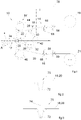
Figure 1 is a schematic view of an apparatus for packaging articles according to the present invention, -
Figures 2 and 3 are schematic details of possible embodiments of tensioning devices for an apparatus according to the present invention, -
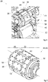
Figure 4 is a partial perspective view of a heating roller indicated by the arrow IV infigure 1 , and -
Figure 5 is a perspective view of a compression unit indicated by the arrow V infigure 1 . - With reference to
Figure 1 ,reference 10 indicates an apparatus for packaging flat articles A in envelope-shaped packages closed around each article A along the edges of the packages. - The articles A may be wound-covering plasters, medicated plasters, pain-relief plasters, heating plasters, and the like.
- The articles A are aligned and spaced apart from each other in a continuous array that advances in a machine direction X on an
inlet conveyor 12. - The
apparatus 10 comprises afirst feeding assembly 14 and asecond feeding assembly 16 that feed, respectively, a firstcontinuous paper sheet 18 and a secondcontinuous paper sheet 20 towards anoverlapping unit 22. - The first and second
continuous paper sheet respective reels continuous paper sheets continuous paper sheets continuous paper sheet - In a possible embodiment, the first
continuous paper sheet 18 may have a specific weight of 8.3 g/m2 and may have a layer of thermally-activated adhesive over an entire surface, and the secondcontinuous paper sheet 20 may have a specific weight of 9 g/m2 and may have on a surface a layer of silicone-like smooth material. The twocontinuous paper sheets continuous paper sheet 18 comes into contact with the smooth surface of the secondcontinuous paper sheet 20. - The overlapping
unit 22 may comprise a pair ofcoupling rollers 24 tangential to each other and rotatable in opposite directions around respective axes parallel to each other and perpendicular to the machine direction X. Thecoupling rollers 24 may be idle around the respective axis of rotation. - The two
continuous paper sheets respective coupling rollers 24 while they advance towards the tangency area of the twocoupling rollers 24. The articles A are fed in the direction X between the twocontinuous paper sheets coupling rollers 24. The twocontinuous paper sheets coupling rollers 24. - Downstream of the overlapping
unit 22, a continuouscomposite tape 26 is formed, comprising twocontinuous paper sheets continuous paper sheets continuous paper sheets continuous paper sheets - The
apparatus 10 comprises acompression unit 28 configured to fix to each other the twocontinuous paper sheets - The overlapping
unit 22 and thecompression unit 28 are two separate modules independent of each other, so that the steps of overlapping and compressing the two continuousflexible sheets flexible sheets flexible sheets - With reference to
figure 4 , thecompression unit 28 comprises a first and a second mutually cooperatingcompression rollers composite tape 26 along a series ofcompression areas 34, each having a frame-like shape which surround respective articles A. Thecompression areas 34 are formed on the peripheral surface of thefirst compression roller 30. Thecompression areas 34 may be defined by two continuouslongitudinal compression elements 36 and by a plurality oftransversal compression elements 38. Thecompression areas 34 may be made of soft material, e.g. by silicone, in order to avoid the formation of markings on the twocontinuous paper sheets first compression roller 30 is not heated, and thesecond compression roller 32 may be heated, e.g. by inner heating resistors. - The
second compression roller 32 may have a smooth outer surface pressed against thelongitudinal compression elements 36 and thetransversal compression elements 38 of thefirst compression roller 30. - With reference to
figure 1 , a first pair of feedingrollers 25 may be arranged between thecoupling rollers 22 and thecompression rollers rollers 42 may be arranged downstream of thecompression rollers rollers composite tape 26 as it passes through thecompression unit 28. The first and second pair of feedingrollers - With reference to
figure 1 , theapparatus 10 comprises a first and asecond heating roller continuous paper sheets unit 22. - With reference to
figure 5 , eachheating roller continuous paper sheet heating areas 48, each having a frame-like shape, formed on the outer surface of theheating roller heating areas 48 have the same shape as thecompression areas 34. Each of theheating roller compression roller 30 of thecompression unit 28. Similarly to thecompression areas 34, theheating areas 48 may be defined by two continuouslongitudinal heating elements 50 and by a plurality oftransversal heating elements 52, which may be made of metal, e.g. by steel. Eachheating area 48 surrounds an insulating portion 54 formed by a thermally insulating material, e.g. Teflon© or Ultem©.Portions 56 of thermally insulating material may also be arranged laterally outwardly to thelongitudinal heating elements 52. - The
heating areas 48 of theheating rollers heating rollers - With reference to
figure 1 , the first andsecond feeding assemblies continuous paper sheet respective heating rollers continuous paper sheet respective heating rollers continuous paper sheet respective heating rollers heating rollers continuous paper sheet continuous paper sheet continuous paper sheet respective heating rollers continuous paper sheet continuous paper sheet respective heating rollers - The
heating rollers continuous paper sheets heating areas 48 at a temperature comprised between 100-200°C, preferably between 160-180°C. - Heating of the first and second
continuous paper sheet second heating roller continuous paper sheet unit 22. In this case, full activation of the thermally-activated adhesive is carried out in thecompression unit 28. In possible embodiments, heating of thecontinuous paper sheets heating rollers compression unit 28. - The
pressure roller 30 of thecompression unit 28, and theheating rollers electronic control unit 78, which drives theheating rollers compression roller 30 around the respective axes at the same speed and maintains theheating areas 48 and thecompression areas 34 in phase with each other, so that the continuouscomposite tape 26 is compressed incompression areas 34 overlapped toheating areas 48 of the first and secondcontinuous paper sheet - The preliminary heating of the continuous
flexible sheets heating rollers compression unit 28. It has been found that by heating the continuousflexible sheets composite tape 26 through thecompression unit 28 at speeds in the order of 200 m/min. Theflexible sheets compression unit 28 at a speed of 150 - 250 m/min, in particular 180 - 210 m/min. The preliminary heating ensures that, even with very high manufacturing speeds, the resulting packages meet all the quality requirements defined by the plaster manufacturers, in particular, uniform transfer of the thermally-activated adhesive to the sheet without the adhesive layer, optimal sealing of the weld, a uniform release force and the guarantee of absence of leaks. - In accordance with a feature of the present invention, the first and
second feeding assembly continuous paper sheet continuous paper sheet respective feeding assembly compression unit 28. In a possible embodiment the tension of the first and secondcontinuous paper sheet compression unit 28. - In prior art solutions, the typical working tension of the continuous paper sheets is usually in a range comprised from a few N up to 20-30 N. It has been found that with feeding speed of the continuous paper sheets of about 200 m/1' with the tension used in the prior art methods there is a poor glue transfer at the center of the transversal sealing portions. It has also been found that as the tension of the first and second
continuous paper sheet heating rollers continuous paper sheet - The reason for an improved sealing quality as the tension increases is that a high tension of the
continuous paper sheets heating rollers heating rollers - It has been found that by gradually increasing the feeding tension of the
continuous paper sheets - Tests carried out by the Applicant showed that a feeding tension of the
continuous paper sheets - The sealing quality at the center of the transverse seal can further increase with higher feeding tensions. The upper limit of the feeding tension can be close to the breaking limit of the paper sheets (about 200 N for the paper sheet having the layer of thermally-activated adhesive and about 150 N for the paper sheet without the layer of thermally-activated adhesive). The lower limit of the feeding tensions is in the range of 50-60 N. It should be noted that these tension values are very different from the feeding tensions of non-woven webs, which usually are comprised in the range of 1-10 N. High feeding tensions in the solution according to the present invention are possible because paper is a material having very small deformability, which can be subjected to tensions close to the braking limit with small stretching.
- Various methods are possible for tensioning the first and second
continuous paper sheet heating rollers - With reference to
figure 1 , in a possible embodiment, the first andsecond feeding assembly respective feeding rollers rollers - In a possible embodiment, the
heating rollers rollers compression rollers continuous paper sheet heating rollers rollers 42 located downstream of thecompression rollers compression rollers e 46 may be slightly different from the peripheral speed of the feedingrollers continuous paper sheet compression rollers e 46. - The
electronic control unit 78 may control the peripheral speed of the feedingrollers tension measuring devices continuous paper sheet tension measuring devices load cell 68 formed by an idle roller on which the first or secondcontinuous paper sheet load cells 68 send to theelectronic control unit 78 signals indicating the longitudinal tensions of the first and secondcontinuous paper sheet continuous paper sheet electronic control unit 78 varies the speed of the feedingrollers continuous paper sheet - With reference to
figure 2 , in a possible embodiment each of the first andsecond feeding assembly tensioning device 70 which applies a transversal force on the respective first or secondcontinuous paper sheet respective heating roller tensioning device 70 may comprise atensioning roller 72 cooperating with the respectivecontinuous paper sheet continuous paper sheet - The tensioning
roller 72 may be carried by a pivoting arm articulated about an axis parallel to the axis of rotation of thetensioning roller 72. A weight may be provided on the pivoting arm to adjust the force applied by the tensioningroller 72 to the respectivecontinuous paper sheet - With reference to
figure 3 , in a possible embodiment thetensioning device 70 may comprise anactuator 74 which moves thetensioning roller 72 transversally to the respectivecontinuous paper sheet - The longitudinal tension of the first and second
continuous paper sheet roller 74 to the respectivecontinuous paper sheet - Feeding the first and second
continuous paper sheet paper sheets heating rollers second feeding unit continuous paper sheet continuous paper sheet continuous paper sheet figure 1 , the reduction of the longitudinal tension of the first and secondcontinuous paper sheet rollers apparatus 10 or by driving for a short time the feedingrollers apparatus 10 is stopped. - In the embodiment of
figures 2 and 3 the reduction of the longitudinal tension of the first and secondcontinuous paper sheet tensioning roller 72, so as to reduce or eliminate the force applied by the tensioningroller 72 to the first and secondcontinuous paper sheet - Of course, without prejudice to the principle of the invention, the details of construction and the embodiments can be widely varied with respect to those described and illustrated, without thereby departing from the scope of the invention as defined by the claims that follow.
Claims (15)
- A method for packaging articles (A) comprising:- feeding in respective longitudinal directions a first and a second continuous paper sheet (18, 20), at least one of which has a thermally-activated adhesive on one surface,- tensioning said first and second continuous paper sheet (18, 20) along respective longitudinal directions with a longitudinal tension comprised between 50 and 200 N,- heating said first and second continuous paper sheet (18, 20) on respective heating rollers (44, 46) while tensioned in longitudinal direction,- feeding a flow of articles (A) between said first and second continuous paper sheet (18, 20),- overlapping the heated and tensioned first and second continuous paper sheet (18, 20) on opposite sides of said flow of articles (A), and- compressing said first and second continuous paper sheet (18, 20) around said articles (A) to fix to each other said first and second continuous paper sheet (18, 20) by said thermally-activated adhesive.
- The method of claim 1, wherein said first and second continuous paper sheet (18, 20) are kept tensioned from upstream of said heating rollers (44, 46) up to said compressing step.
- The method of claim 1 or claim 2, wherein said first and second continuous paper sheet (18, 20) are tensioned by controlling the respective feeding speeds upstream of said heating rollers (44, 46).
- The method of claim 3, comprising measuring the longitudinal tension of the first and second continuous paper sheet (18, 20) and controlling said feeding speeds on the basis of the measured tensions.
- The method of claim 1 or claim 2, wherein said first and second continuous paper sheet are tensioned by applying to said first and second continuous paper sheet (18, 20) a transversal tensioning force by means of a respective tensioning roller (72).
- The method of any of the preceding claims, wherein said longitudinal tension is reduced when feeding of said first and second continuous paper sheet (18, 20) is stopped.
- The method of any of the preceding claims, wherein said first and second continuous paper sheet (18, 20) are heated along heating areas (48) each having a frame-like shape.
- The method of claim 7, wherein said first and second continuous paper sheet (18, 20) are compressed along compression areas (34) surrounding respective articles (A), each having a frame-like shape and overlapped to respective heating areas (48).
- The method of claim 7, wherein during said compression step said first and second continuous paper sheet (18, 20) are heated along said compression areas (34) .
- An apparatus for packaging articles (A) comprising:- a first and a second feeding assembly (14, 16) configured for feeding in respective longitudinal directions a first and a second continuous paper sheet (18, 20) at least one of which has a thermally-activated adhesive on one surface, the first and second feeding assembly (14, 16) being configured for feeding said first and second continuous paper sheet (18, 20) with a longitudinal tension comprised between 50 and 200 N,- a first and second heating roller (44, 46) configured for heating said first and second continuous paper sheet (18, 20) while tensioned in longitudinal direction,- an inlet conveyor (12) configured for feeding a flow of articles (A) between said first and second continuous paper sheet (18, 20),- an overlapping unit (22) configured for overlapping to each other the heated and tensioned first and second continuous paper sheet (18, 20) on opposite sides of said flow of articles (A), and- a compression unit (28) configured for compressing said first and second continuous paper sheet (18, 20) around said articles (A) to fix to each other said continuous paper sheets (18, 20) by said thermally-activated adhesive.
- The apparatus of claim 10, wherein said first and second feeding assembly (14, 16) are configured for controlling the longitudinal tension of the first and second continuous paper sheet (18, 20) by controlling the respective feeding speeds.
- The apparatus of claim 10, wherein said first and second feeding assembly (14, 16) comprise respective tensioning rollers (72) configured for applying a transversal tensioning force to the respective first and second continuous paper sheet (18, 20).
- The apparatus of any of claims 10-12, wherein said first and second feeding assembly (14, 16) are configured for reducing the longitudinal tension of said first and a second continuous paper sheet (18, 20) when feeding of said first and second continuous paper sheet (18, 20) is stopped.
- The apparatus of any of claims 10-13, wherein each of said heating rollers (44, 46) has a plurality of heating areas (48) each having a frame-like shape, surrounded by thermally insulating material.
- The apparatus of claim 14, wherein said compression unit (28) comprises a compression roller (30) having a plurality of compression areas (34) each having a frame-like shape, in phase with said heating areas (34) of said heating rollers (44, 46).
Priority Applications (6)
| Application Number | Priority Date | Filing Date | Title |
|---|---|---|---|
| PL21179387.2T PL4105133T3 (en) | 2021-06-15 | 2021-06-15 | A method and an apparatus for packaging articles |
| ES21179387T ES2985335T3 (en) | 2021-06-15 | 2021-06-15 | Procedure and apparatus for packaging articles |
| EP21179387.2A EP4105133B1 (en) | 2021-06-15 | 2021-06-15 | A method and an apparatus for packaging articles |
| BR102022009229-0A BR102022009229B1 (en) | 2021-06-15 | 2022-05-12 | A METHOD AND APPARATUS FOR PACKAGING ARTICLES |
| US17/836,420 US12091206B2 (en) | 2021-06-15 | 2022-06-09 | Method and an apparatus for packaging articles |
| CN202210681212.5A CN115475099B (en) | 2021-06-15 | 2022-06-15 | Method and apparatus for packaging articles |
Applications Claiming Priority (1)
| Application Number | Priority Date | Filing Date | Title |
|---|---|---|---|
| EP21179387.2A EP4105133B1 (en) | 2021-06-15 | 2021-06-15 | A method and an apparatus for packaging articles |
Publications (2)
| Publication Number | Publication Date |
|---|---|
| EP4105133A1 true EP4105133A1 (en) | 2022-12-21 |
| EP4105133B1 EP4105133B1 (en) | 2024-08-07 |
Family
ID=76483036
Family Applications (1)
| Application Number | Title | Priority Date | Filing Date |
|---|---|---|---|
| EP21179387.2A Active EP4105133B1 (en) | 2021-06-15 | 2021-06-15 | A method and an apparatus for packaging articles |
Country Status (5)
| Country | Link |
|---|---|
| US (1) | US12091206B2 (en) |
| EP (1) | EP4105133B1 (en) |
| CN (1) | CN115475099B (en) |
| ES (1) | ES2985335T3 (en) |
| PL (1) | PL4105133T3 (en) |
Families Citing this family (1)
| Publication number | Priority date | Publication date | Assignee | Title |
|---|---|---|---|---|
| EP4151541B1 (en) * | 2021-09-20 | 2025-11-05 | Fameccanica.Data S.p.A. | An apparatus and method for heating a movable web |
Citations (5)
| Publication number | Priority date | Publication date | Assignee | Title |
|---|---|---|---|---|
| DE812416C (en) * | 1946-08-27 | 1951-08-30 | Wingfoot Corp | Packaging process, especially for sensitive and fragile objects |
| US3140572A (en) * | 1957-09-17 | 1964-07-14 | American White Cross Lab Inc | Surgical dressing packaging |
| DE1266681B (en) * | 1963-03-02 | 1968-04-18 | Noack E Th Verpackungsmasch | Plant for packaging adhesive plaster |
| US5613601A (en) | 1993-09-24 | 1997-03-25 | Johnson & Johnson Inc. | Package for dispensing a fluid treating substance and method and apparatus for heat-sealing the dispensing package |
| US20080047658A1 (en) * | 2006-08-28 | 2008-02-28 | Curt G. Joa, Inc. | Bonding method for continuous traveling web |
Family Cites Families (31)
| Publication number | Priority date | Publication date | Assignee | Title |
|---|---|---|---|---|
| US2486759A (en) * | 1938-02-28 | 1949-11-01 | Jesse R Crossan | Packaging method and apparatus |
| US2374504A (en) * | 1944-10-31 | 1945-04-24 | Ivers Lee Co | Sealing and crimping rollers for packaging machines |
| US2579415A (en) * | 1946-12-04 | 1951-12-18 | Wingfoot Corp | Packaging process |
| US2586580A (en) * | 1948-04-06 | 1952-02-19 | Wingfoot Corp | Heat sealed wrapping machine and method of wrapping |
| US2871639A (en) * | 1957-02-04 | 1959-02-03 | Battle Creek Packaging Machine | Wrapper indexing mechanism for wrapping machines |
| US3751875A (en) * | 1971-09-09 | 1973-08-14 | H Membrino | Apparatus for filling, sealing and dispensing bags |
| ES2017634B3 (en) * | 1985-12-24 | 1991-03-01 | Omnitech (Europe) Ltd | HORIZONTAL INTRODUCTION PACKING MACHINE |
| US4711066A (en) * | 1986-09-09 | 1987-12-08 | The Surgimach Corporation | Method and apparatus for packaging medical gauze sponges |
| JP3110090B2 (en) * | 1991-08-23 | 2000-11-20 | 積水化学工業株式会社 | Manufacturing method of medical patch |
| US5740661A (en) * | 1995-05-23 | 1998-04-21 | Sumitomo Chemical Company, Limited | Method and apparatus of producing sheet wrapping body |
| DE69710426T2 (en) * | 1996-11-29 | 2002-10-02 | Kabushiki Kaisha Hayashibara Seibutsu Kagaku Kenkyujo, Okayama | Packaging for inclusion product and process for its manufacture |
| SE509440C2 (en) * | 1997-05-14 | 1999-01-25 | Tetra Laval Holdings & Finance | Methods of preparing a color-ink-packed packaging material, especially for aseptic packaging, and packaging containers thereof |
| US5875614A (en) * | 1997-09-25 | 1999-03-02 | Univenture Inc. | Apparatus and methods for forming flexible packaging containers for discs |
| IT1299941B1 (en) * | 1998-03-27 | 2000-04-04 | Tecnomeccanica Srl | EQUIPMENT FOR THE FORMING OF A WELDABLE PAPER WRAP FOR THE PACKAGING OF A PRODUCT. |
| KR100416227B1 (en) * | 2001-10-23 | 2004-01-31 | (주)제이브이메디 | Interval adjuster of vertical sealing of packing sheet for sharing and packing device of medicine |
| US6979482B2 (en) * | 2002-11-08 | 2005-12-27 | Exopack-Technology, Llc | Multiwall bag with zipper and fin |
| US7302781B2 (en) * | 2004-09-21 | 2007-12-04 | C.G. Bretting Manufacturing Company, Inc. | Bander apparatus and method of using same |
| US7594372B2 (en) * | 2006-03-14 | 2009-09-29 | Scholle Corporation | Flexible container forming apparatus having integrated web surface deformation |
| WO2008021426A2 (en) * | 2006-08-15 | 2008-02-21 | Zynon Technologies, Llc | Sealed package and method of making |
| US8231024B2 (en) * | 2007-08-08 | 2012-07-31 | Clear Lam Packaging, Inc. | Flexible, stackable container and method and system for manufacturing same |
| BR112012000500A2 (en) * | 2009-07-08 | 2016-02-16 | Nestec Sa | Flexible sachet and manufacturing method |
| US20110083810A1 (en) * | 2009-10-13 | 2011-04-14 | David Lin | Container Sealing Machine for Food Packaging |
| AU2014310655B2 (en) * | 2013-08-20 | 2020-03-05 | Swm Luxembourg | Product comprising a plant for medicinal, cosmetic, coloring or dermatologic use |
| CN106275645A (en) * | 2015-05-15 | 2017-01-04 | 可口可乐公司 | A kind of online molding, fill and encapsulate formed product packaging system and method |
| ITUB20153482A1 (en) * | 2015-09-08 | 2015-12-08 | Fameccanica Data Spa | THREE-DIMENSIONAL COMPOSITE TAPE, PROCEDURE AND APPARATUS FOR ITS PRODUCTION |
| US10251966B2 (en) * | 2015-10-06 | 2019-04-09 | Satellite Industries, Inc. | Odor control product package and method of forming the same |
| CN106214490A (en) * | 2016-08-31 | 2016-12-14 | 贵州苗仁堂生物医药科技有限责任公司 | A kind of continuous way black ointment machine |
| EP4382296A3 (en) * | 2017-02-28 | 2024-08-28 | Kimberly-Clark Worldwide, Inc. | Elasticated materials with directional stretch properties |
| WO2019060206A1 (en) * | 2017-09-20 | 2019-03-28 | Triangle Package Machinery Co. | Vertical form, fill and seal machine with ultrasonic vertical seal and reclosable fastener attachment |
| JP7245491B2 (en) * | 2018-10-04 | 2023-03-24 | 株式会社イシダ | bag making and packaging machine |
| EP4387842A4 (en) * | 2021-08-16 | 2025-07-16 | Millimeter Wave Products Inc Tlc | SAMPLE ENCAPSULATION SYSTEM |
-
2021
- 2021-06-15 PL PL21179387.2T patent/PL4105133T3/en unknown
- 2021-06-15 ES ES21179387T patent/ES2985335T3/en active Active
- 2021-06-15 EP EP21179387.2A patent/EP4105133B1/en active Active
-
2022
- 2022-06-09 US US17/836,420 patent/US12091206B2/en active Active
- 2022-06-15 CN CN202210681212.5A patent/CN115475099B/en active Active
Patent Citations (5)
| Publication number | Priority date | Publication date | Assignee | Title |
|---|---|---|---|---|
| DE812416C (en) * | 1946-08-27 | 1951-08-30 | Wingfoot Corp | Packaging process, especially for sensitive and fragile objects |
| US3140572A (en) * | 1957-09-17 | 1964-07-14 | American White Cross Lab Inc | Surgical dressing packaging |
| DE1266681B (en) * | 1963-03-02 | 1968-04-18 | Noack E Th Verpackungsmasch | Plant for packaging adhesive plaster |
| US5613601A (en) | 1993-09-24 | 1997-03-25 | Johnson & Johnson Inc. | Package for dispensing a fluid treating substance and method and apparatus for heat-sealing the dispensing package |
| US20080047658A1 (en) * | 2006-08-28 | 2008-02-28 | Curt G. Joa, Inc. | Bonding method for continuous traveling web |
Also Published As
| Publication number | Publication date |
|---|---|
| US12091206B2 (en) | 2024-09-17 |
| EP4105133B1 (en) | 2024-08-07 |
| BR102022009229A2 (en) | 2022-12-27 |
| CN115475099B (en) | 2025-06-20 |
| ES2985335T3 (en) | 2024-11-05 |
| US20220396381A1 (en) | 2022-12-15 |
| CN115475099A (en) | 2022-12-16 |
| PL4105133T3 (en) | 2024-10-07 |
Similar Documents
| Publication | Publication Date | Title |
|---|---|---|
| RU2564871C2 (en) | Device and methods of packaging food products | |
| US6228458B1 (en) | Package with tear tape and method of forming same | |
| US11505392B2 (en) | Edge protector and method of manufacturing same | |
| US12091206B2 (en) | Method and an apparatus for packaging articles | |
| CZ9402005A3 (en) | Device for packaging foodstuffs when producing individually packed slices, and process for producing thereof | |
| US12415638B2 (en) | Method and an apparatus for packaging articles | |
| US12070910B2 (en) | Apparatus and method for heating a movable web | |
| KR20170094132A (en) | Apparatus and method for manufacturing a wrapped endless rod of substantially flat continuous material | |
| AU2016241598A1 (en) | Improvements in and relating to packaging | |
| JP2008094456A (en) | Vertical seal mechanism | |
| CA2599167A1 (en) | Bonding method for continuous traveling web | |
| BR102022009229B1 (en) | A METHOD AND APPARATUS FOR PACKAGING ARTICLES | |
| JPH1086916A (en) | Apparatus for joining strip for press through pack with film web | |
| TW201628925A (en) | Horizontal pillow packaging apparatus and horizontal pillow packaging method | |
| CN215662116U (en) | Production and manufacturing equipment for windowing bag | |
| BR102022016813B1 (en) | APPARATUS AND METHOD FOR PACKAGING ARTICLES AND HEATING UNIT | |
| JP4574584B2 (en) | Vertical seal bonding mechanism for paper containers | |
| IT202400003913A1 (en) | UNIT FOR SPLICING A SEALING STRIP OF HEAT-SEALABLE MATERIAL, APPARATUS FOR APPLYING A SEALING STRIP TO A STRIP OF PACKAGING MATERIAL AND PACKAGING MACHINE FOR FORMING SEALED PACKAGES | |
| JPH04189110A (en) | Sheetlike molding material and both ends treatment device of sheetlike molding material | |
| FI4188809T3 (en) | Apparatus and method for wrapping a load | |
| CN120135551A (en) | Asphalt waterproofing membrane packaging device | |
| JP2004099133A (en) | Sealing method, sealing device and filling and packaging machine | |
| JP2005247387A (en) | Method and device for packaging bundle of linear objects | |
| HK1141772A (en) | Method of forming a cutting auxiliary line | |
| HK1146399A (en) | Wrapping material |
Legal Events
| Date | Code | Title | Description |
|---|---|---|---|
| PUAI | Public reference made under article 153(3) epc to a published international application that has entered the european phase |
Free format text: ORIGINAL CODE: 0009012 |
|
| STAA | Information on the status of an ep patent application or granted ep patent |
Free format text: STATUS: THE APPLICATION HAS BEEN PUBLISHED |
|
| AK | Designated contracting states |
Kind code of ref document: A1 Designated state(s): AL AT BE BG CH CY CZ DE DK EE ES FI FR GB GR HR HU IE IS IT LI LT LU LV MC MK MT NL NO PL PT RO RS SE SI SK SM TR |
|
| STAA | Information on the status of an ep patent application or granted ep patent |
Free format text: STATUS: REQUEST FOR EXAMINATION WAS MADE |
|
| 17P | Request for examination filed |
Effective date: 20230320 |
|
| RBV | Designated contracting states (corrected) |
Designated state(s): AL AT BE BG CH CY CZ DE DK EE ES FI FR GB GR HR HU IE IS IT LI LT LU LV MC MK MT NL NO PL PT RO RS SE SI SK SM TR |
|
| RIC1 | Information provided on ipc code assigned before grant |
Ipc: B65B 57/04 20060101ALI20230717BHEP Ipc: B65B 51/28 20060101ALI20230717BHEP Ipc: B65B 51/16 20060101ALI20230717BHEP Ipc: B65B 51/02 20060101ALI20230717BHEP Ipc: B65B 29/02 20060101ALI20230717BHEP Ipc: B65B 9/02 20060101AFI20230717BHEP |
|
| GRAP | Despatch of communication of intention to grant a patent |
Free format text: ORIGINAL CODE: EPIDOSNIGR1 |
|
| STAA | Information on the status of an ep patent application or granted ep patent |
Free format text: STATUS: GRANT OF PATENT IS INTENDED |
|
| INTG | Intention to grant announced |
Effective date: 20231024 |
|
| GRAJ | Information related to disapproval of communication of intention to grant by the applicant or resumption of examination proceedings by the epo deleted |
Free format text: ORIGINAL CODE: EPIDOSDIGR1 |
|
| GRAL | Information related to payment of fee for publishing/printing deleted |
Free format text: ORIGINAL CODE: EPIDOSDIGR3 |
|
| GRAS | Grant fee paid |
Free format text: ORIGINAL CODE: EPIDOSNIGR3 |
|
| STAA | Information on the status of an ep patent application or granted ep patent |
Free format text: STATUS: REQUEST FOR EXAMINATION WAS MADE |
|
| INTC | Intention to grant announced (deleted) | ||
| GRAP | Despatch of communication of intention to grant a patent |
Free format text: ORIGINAL CODE: EPIDOSNIGR1 |
|
| STAA | Information on the status of an ep patent application or granted ep patent |
Free format text: STATUS: GRANT OF PATENT IS INTENDED |
|
| INTG | Intention to grant announced |
Effective date: 20240419 |
|
| GRAS | Grant fee paid |
Free format text: ORIGINAL CODE: EPIDOSNIGR3 |
|
| GRAA | (expected) grant |
Free format text: ORIGINAL CODE: 0009210 |
|
| STAA | Information on the status of an ep patent application or granted ep patent |
Free format text: STATUS: THE PATENT HAS BEEN GRANTED |
|
| AK | Designated contracting states |
Kind code of ref document: B1 Designated state(s): AL AT BE BG CH CY CZ DE DK EE ES FI FR GB GR HR HU IE IS IT LI LT LU LV MC MK MT NL NO PL PT RO RS SE SI SK SM TR |
|
| REG | Reference to a national code |
Ref country code: GB Ref legal event code: FG4D |
|
| REG | Reference to a national code |
Ref country code: CH Ref legal event code: EP |
|
| REG | Reference to a national code |
Ref country code: NL Ref legal event code: FP Ref country code: IE Ref legal event code: FG4D |
|
| REG | Reference to a national code |
Ref country code: DE Ref legal event code: R096 Ref document number: 602021016692 Country of ref document: DE |
|
| REG | Reference to a national code |
Ref country code: SE Ref legal event code: TRGR |
|
| REG | Reference to a national code |
Ref country code: ES Ref legal event code: FG2A Ref document number: 2985335 Country of ref document: ES Kind code of ref document: T3 Effective date: 20241105 |
|
| REG | Reference to a national code |
Ref country code: AT Ref legal event code: UEP Ref document number: 1710676 Country of ref document: AT Kind code of ref document: T Effective date: 20240807 |
|
| REG | Reference to a national code |
Ref country code: LT Ref legal event code: MG9D |
|
| PG25 | Lapsed in a contracting state [announced via postgrant information from national office to epo] |
Ref country code: NO Free format text: LAPSE BECAUSE OF FAILURE TO SUBMIT A TRANSLATION OF THE DESCRIPTION OR TO PAY THE FEE WITHIN THE PRESCRIBED TIME-LIMIT Effective date: 20241107 |
|
| PG25 | Lapsed in a contracting state [announced via postgrant information from national office to epo] |
Ref country code: PT Free format text: LAPSE BECAUSE OF FAILURE TO SUBMIT A TRANSLATION OF THE DESCRIPTION OR TO PAY THE FEE WITHIN THE PRESCRIBED TIME-LIMIT Effective date: 20241209 Ref country code: GR Free format text: LAPSE BECAUSE OF FAILURE TO SUBMIT A TRANSLATION OF THE DESCRIPTION OR TO PAY THE FEE WITHIN THE PRESCRIBED TIME-LIMIT Effective date: 20241108 Ref country code: FI Free format text: LAPSE BECAUSE OF FAILURE TO SUBMIT A TRANSLATION OF THE DESCRIPTION OR TO PAY THE FEE WITHIN THE PRESCRIBED TIME-LIMIT Effective date: 20240807 |
|
| PG25 | Lapsed in a contracting state [announced via postgrant information from national office to epo] |
Ref country code: BG Free format text: LAPSE BECAUSE OF FAILURE TO SUBMIT A TRANSLATION OF THE DESCRIPTION OR TO PAY THE FEE WITHIN THE PRESCRIBED TIME-LIMIT Effective date: 20240807 |
|
| PG25 | Lapsed in a contracting state [announced via postgrant information from national office to epo] |
Ref country code: LV Free format text: LAPSE BECAUSE OF FAILURE TO SUBMIT A TRANSLATION OF THE DESCRIPTION OR TO PAY THE FEE WITHIN THE PRESCRIBED TIME-LIMIT Effective date: 20240807 |
|
| PG25 | Lapsed in a contracting state [announced via postgrant information from national office to epo] |
Ref country code: IS Free format text: LAPSE BECAUSE OF FAILURE TO SUBMIT A TRANSLATION OF THE DESCRIPTION OR TO PAY THE FEE WITHIN THE PRESCRIBED TIME-LIMIT Effective date: 20241207 |
|
| PG25 | Lapsed in a contracting state [announced via postgrant information from national office to epo] |
Ref country code: HR Free format text: LAPSE BECAUSE OF FAILURE TO SUBMIT A TRANSLATION OF THE DESCRIPTION OR TO PAY THE FEE WITHIN THE PRESCRIBED TIME-LIMIT Effective date: 20240807 |
|
| PG25 | Lapsed in a contracting state [announced via postgrant information from national office to epo] |
Ref country code: RS Free format text: LAPSE BECAUSE OF FAILURE TO SUBMIT A TRANSLATION OF THE DESCRIPTION OR TO PAY THE FEE WITHIN THE PRESCRIBED TIME-LIMIT Effective date: 20241107 |
|
| PG25 | Lapsed in a contracting state [announced via postgrant information from national office to epo] |
Ref country code: RS Free format text: LAPSE BECAUSE OF FAILURE TO SUBMIT A TRANSLATION OF THE DESCRIPTION OR TO PAY THE FEE WITHIN THE PRESCRIBED TIME-LIMIT Effective date: 20241107 Ref country code: PT Free format text: LAPSE BECAUSE OF FAILURE TO SUBMIT A TRANSLATION OF THE DESCRIPTION OR TO PAY THE FEE WITHIN THE PRESCRIBED TIME-LIMIT Effective date: 20241209 Ref country code: NO Free format text: LAPSE BECAUSE OF FAILURE TO SUBMIT A TRANSLATION OF THE DESCRIPTION OR TO PAY THE FEE WITHIN THE PRESCRIBED TIME-LIMIT Effective date: 20241107 Ref country code: LV Free format text: LAPSE BECAUSE OF FAILURE TO SUBMIT A TRANSLATION OF THE DESCRIPTION OR TO PAY THE FEE WITHIN THE PRESCRIBED TIME-LIMIT Effective date: 20240807 Ref country code: IS Free format text: LAPSE BECAUSE OF FAILURE TO SUBMIT A TRANSLATION OF THE DESCRIPTION OR TO PAY THE FEE WITHIN THE PRESCRIBED TIME-LIMIT Effective date: 20241207 Ref country code: HR Free format text: LAPSE BECAUSE OF FAILURE TO SUBMIT A TRANSLATION OF THE DESCRIPTION OR TO PAY THE FEE WITHIN THE PRESCRIBED TIME-LIMIT Effective date: 20240807 Ref country code: GR Free format text: LAPSE BECAUSE OF FAILURE TO SUBMIT A TRANSLATION OF THE DESCRIPTION OR TO PAY THE FEE WITHIN THE PRESCRIBED TIME-LIMIT Effective date: 20241108 Ref country code: FI Free format text: LAPSE BECAUSE OF FAILURE TO SUBMIT A TRANSLATION OF THE DESCRIPTION OR TO PAY THE FEE WITHIN THE PRESCRIBED TIME-LIMIT Effective date: 20240807 Ref country code: BG Free format text: LAPSE BECAUSE OF FAILURE TO SUBMIT A TRANSLATION OF THE DESCRIPTION OR TO PAY THE FEE WITHIN THE PRESCRIBED TIME-LIMIT Effective date: 20240807 |
|
| PG25 | Lapsed in a contracting state [announced via postgrant information from national office to epo] |
Ref country code: DK Free format text: LAPSE BECAUSE OF FAILURE TO SUBMIT A TRANSLATION OF THE DESCRIPTION OR TO PAY THE FEE WITHIN THE PRESCRIBED TIME-LIMIT Effective date: 20240807 Ref country code: SM Free format text: LAPSE BECAUSE OF FAILURE TO SUBMIT A TRANSLATION OF THE DESCRIPTION OR TO PAY THE FEE WITHIN THE PRESCRIBED TIME-LIMIT Effective date: 20240807 |
|
| PG25 | Lapsed in a contracting state [announced via postgrant information from national office to epo] |
Ref country code: EE Free format text: LAPSE BECAUSE OF FAILURE TO SUBMIT A TRANSLATION OF THE DESCRIPTION OR TO PAY THE FEE WITHIN THE PRESCRIBED TIME-LIMIT Effective date: 20240807 |
|
| PG25 | Lapsed in a contracting state [announced via postgrant information from national office to epo] |
Ref country code: CZ Free format text: LAPSE BECAUSE OF FAILURE TO SUBMIT A TRANSLATION OF THE DESCRIPTION OR TO PAY THE FEE WITHIN THE PRESCRIBED TIME-LIMIT Effective date: 20240807 |
|
| PG25 | Lapsed in a contracting state [announced via postgrant information from national office to epo] |
Ref country code: SK Free format text: LAPSE BECAUSE OF FAILURE TO SUBMIT A TRANSLATION OF THE DESCRIPTION OR TO PAY THE FEE WITHIN THE PRESCRIBED TIME-LIMIT Effective date: 20240807 |
|
| REG | Reference to a national code |
Ref country code: DE Ref legal event code: R097 Ref document number: 602021016692 Country of ref document: DE |
|
| PLBE | No opposition filed within time limit |
Free format text: ORIGINAL CODE: 0009261 |
|
| STAA | Information on the status of an ep patent application or granted ep patent |
Free format text: STATUS: NO OPPOSITION FILED WITHIN TIME LIMIT |
|
| PGFP | Annual fee paid to national office [announced via postgrant information from national office to epo] |
Ref country code: PL Payment date: 20250523 Year of fee payment: 5 Ref country code: DE Payment date: 20250627 Year of fee payment: 5 |
|
| PGFP | Annual fee paid to national office [announced via postgrant information from national office to epo] |
Ref country code: GB Payment date: 20250627 Year of fee payment: 5 |
|
| PGFP | Annual fee paid to national office [announced via postgrant information from national office to epo] |
Ref country code: NL Payment date: 20250626 Year of fee payment: 5 Ref country code: BE Payment date: 20250627 Year of fee payment: 5 |
|
| 26N | No opposition filed |
Effective date: 20250508 |
|
| PGFP | Annual fee paid to national office [announced via postgrant information from national office to epo] |
Ref country code: FR Payment date: 20250625 Year of fee payment: 5 |
|
| PGFP | Annual fee paid to national office [announced via postgrant information from national office to epo] |
Ref country code: AT Payment date: 20250721 Year of fee payment: 5 |
|
| PGFP | Annual fee paid to national office [announced via postgrant information from national office to epo] |
Ref country code: SE Payment date: 20250627 Year of fee payment: 5 |
|
| PGFP | Annual fee paid to national office [announced via postgrant information from national office to epo] |
Ref country code: ES Payment date: 20250701 Year of fee payment: 5 |
|
| PGFP | Annual fee paid to national office [announced via postgrant information from national office to epo] |
Ref country code: CH Payment date: 20250701 Year of fee payment: 5 |
|
| PG25 | Lapsed in a contracting state [announced via postgrant information from national office to epo] |
Ref country code: MC Free format text: LAPSE BECAUSE OF FAILURE TO SUBMIT A TRANSLATION OF THE DESCRIPTION OR TO PAY THE FEE WITHIN THE PRESCRIBED TIME-LIMIT Effective date: 20240807 |
|
| PG25 | Lapsed in a contracting state [announced via postgrant information from national office to epo] |
Ref country code: LU Free format text: LAPSE BECAUSE OF NON-PAYMENT OF DUE FEES Effective date: 20250615 |
|
| PG25 | Lapsed in a contracting state [announced via postgrant information from national office to epo] |
Ref country code: IE Free format text: LAPSE BECAUSE OF NON-PAYMENT OF DUE FEES Effective date: 20250615 |
|
| PG25 | Lapsed in a contracting state [announced via postgrant information from national office to epo] |
Ref country code: IT Free format text: LAPSE BECAUSE OF NON-PAYMENT OF DUE FEES Effective date: 20250615 Ref country code: RO Free format text: LAPSE BECAUSE OF FAILURE TO SUBMIT A TRANSLATION OF THE DESCRIPTION OR TO PAY THE FEE WITHIN THE PRESCRIBED TIME-LIMIT Effective date: 20240807 |