EP4105120A1 - Eha system for lifting/lowering landing gear - Google Patents
Eha system for lifting/lowering landing gear Download PDFInfo
- Publication number
- EP4105120A1 EP4105120A1 EP20925654.4A EP20925654A EP4105120A1 EP 4105120 A1 EP4105120 A1 EP 4105120A1 EP 20925654 A EP20925654 A EP 20925654A EP 4105120 A1 EP4105120 A1 EP 4105120A1
- Authority
- EP
- European Patent Office
- Prior art keywords
- hydraulic pump
- electric hydraulic
- electric
- leg
- lifting
- Prior art date
- Legal status (The legal status is an assumption and is not a legal conclusion. Google has not performed a legal analysis and makes no representation as to the accuracy of the status listed.)
- Granted
Links
Images


Classifications
-
- F—MECHANICAL ENGINEERING; LIGHTING; HEATING; WEAPONS; BLASTING
- F04—POSITIVE - DISPLACEMENT MACHINES FOR LIQUIDS; PUMPS FOR LIQUIDS OR ELASTIC FLUIDS
- F04B—POSITIVE-DISPLACEMENT MACHINES FOR LIQUIDS; PUMPS
- F04B51/00—Testing machines, pumps, or pumping installations
-
- B—PERFORMING OPERATIONS; TRANSPORTING
- B64—AIRCRAFT; AVIATION; COSMONAUTICS
- B64C—AEROPLANES; HELICOPTERS
- B64C25/00—Alighting gear
- B64C25/02—Undercarriages
- B64C25/08—Undercarriages non-fixed, e.g. jettisonable
- B64C25/10—Undercarriages non-fixed, e.g. jettisonable retractable, foldable, or the like
- B64C25/18—Operating mechanisms
- B64C25/22—Operating mechanisms fluid
-
- B—PERFORMING OPERATIONS; TRANSPORTING
- B64—AIRCRAFT; AVIATION; COSMONAUTICS
- B64C—AEROPLANES; HELICOPTERS
- B64C25/00—Alighting gear
- B64C25/02—Undercarriages
- B64C25/08—Undercarriages non-fixed, e.g. jettisonable
- B64C25/10—Undercarriages non-fixed, e.g. jettisonable retractable, foldable, or the like
- B64C25/18—Operating mechanisms
- B64C25/24—Operating mechanisms electric
-
- B—PERFORMING OPERATIONS; TRANSPORTING
- B64—AIRCRAFT; AVIATION; COSMONAUTICS
- B64C—AEROPLANES; HELICOPTERS
- B64C25/00—Alighting gear
- B64C25/02—Undercarriages
- B64C25/08—Undercarriages non-fixed, e.g. jettisonable
- B64C25/10—Undercarriages non-fixed, e.g. jettisonable retractable, foldable, or the like
- B64C25/18—Operating mechanisms
- B64C25/26—Control or locking systems therefor
- B64C25/28—Control or locking systems therefor with indicating or warning devices
-
- F—MECHANICAL ENGINEERING; LIGHTING; HEATING; WEAPONS; BLASTING
- F04—POSITIVE - DISPLACEMENT MACHINES FOR LIQUIDS; PUMPS FOR LIQUIDS OR ELASTIC FLUIDS
- F04B—POSITIVE-DISPLACEMENT MACHINES FOR LIQUIDS; PUMPS
- F04B17/00—Pumps characterised by combination with, or adaptation to, specific driving engines or motors
- F04B17/03—Pumps characterised by combination with, or adaptation to, specific driving engines or motors driven by electric motors
-
- F—MECHANICAL ENGINEERING; LIGHTING; HEATING; WEAPONS; BLASTING
- F04—POSITIVE - DISPLACEMENT MACHINES FOR LIQUIDS; PUMPS FOR LIQUIDS OR ELASTIC FLUIDS
- F04B—POSITIVE-DISPLACEMENT MACHINES FOR LIQUIDS; PUMPS
- F04B23/00—Pumping installations or systems
- F04B23/04—Combinations of two or more pumps
-
- F—MECHANICAL ENGINEERING; LIGHTING; HEATING; WEAPONS; BLASTING
- F04—POSITIVE - DISPLACEMENT MACHINES FOR LIQUIDS; PUMPS FOR LIQUIDS OR ELASTIC FLUIDS
- F04B—POSITIVE-DISPLACEMENT MACHINES FOR LIQUIDS; PUMPS
- F04B49/00—Control, e.g. of pump delivery, or pump pressure of, or safety measures for, machines, pumps, or pumping installations, not otherwise provided for, or of interest apart from, groups F04B1/00 - F04B47/00
- F04B49/10—Other safety measures
- F04B49/103—Responsive to speed
-
- F—MECHANICAL ENGINEERING; LIGHTING; HEATING; WEAPONS; BLASTING
- F04—POSITIVE - DISPLACEMENT MACHINES FOR LIQUIDS; PUMPS FOR LIQUIDS OR ELASTIC FLUIDS
- F04B—POSITIVE-DISPLACEMENT MACHINES FOR LIQUIDS; PUMPS
- F04B49/00—Control, e.g. of pump delivery, or pump pressure of, or safety measures for, machines, pumps, or pumping installations, not otherwise provided for, or of interest apart from, groups F04B1/00 - F04B47/00
- F04B49/10—Other safety measures
- F04B49/106—Responsive to pumped volume
-
- F—MECHANICAL ENGINEERING; LIGHTING; HEATING; WEAPONS; BLASTING
- F15—FLUID-PRESSURE ACTUATORS; HYDRAULICS OR PNEUMATICS IN GENERAL
- F15B—SYSTEMS ACTING BY MEANS OF FLUIDS IN GENERAL; FLUID-PRESSURE ACTUATORS, e.g. SERVOMOTORS; DETAILS OF FLUID-PRESSURE SYSTEMS, NOT OTHERWISE PROVIDED FOR
- F15B15/00—Fluid-actuated devices for displacing a member from one position to another; Gearing associated therewith
- F15B15/20—Other details, e.g. assembly with regulating devices
-
- F—MECHANICAL ENGINEERING; LIGHTING; HEATING; WEAPONS; BLASTING
- F15—FLUID-PRESSURE ACTUATORS; HYDRAULICS OR PNEUMATICS IN GENERAL
- F15B—SYSTEMS ACTING BY MEANS OF FLUIDS IN GENERAL; FLUID-PRESSURE ACTUATORS, e.g. SERVOMOTORS; DETAILS OF FLUID-PRESSURE SYSTEMS, NOT OTHERWISE PROVIDED FOR
- F15B19/00—Testing; Calibrating; Fault detection or monitoring; Simulation or modelling of fluid-pressure systems or apparatus not otherwise provided for
- F15B19/005—Fault detection or monitoring
-
- B—PERFORMING OPERATIONS; TRANSPORTING
- B64—AIRCRAFT; AVIATION; COSMONAUTICS
- B64D—EQUIPMENT FOR FITTING IN OR TO AIRCRAFT; FLIGHT SUITS; PARACHUTES; ARRANGEMENT OR MOUNTING OF POWER PLANTS OR PROPULSION TRANSMISSIONS IN AIRCRAFT
- B64D45/00—Aircraft indicators or protectors not otherwise provided for
- B64D2045/0085—Devices for aircraft health monitoring, e.g. monitoring flutter or vibration
-
- F—MECHANICAL ENGINEERING; LIGHTING; HEATING; WEAPONS; BLASTING
- F04—POSITIVE - DISPLACEMENT MACHINES FOR LIQUIDS; PUMPS FOR LIQUIDS OR ELASTIC FLUIDS
- F04B—POSITIVE-DISPLACEMENT MACHINES FOR LIQUIDS; PUMPS
- F04B2203/00—Motor parameters
- F04B2203/02—Motor parameters of rotating electric motors
- F04B2203/0209—Rotational speed
-
- F—MECHANICAL ENGINEERING; LIGHTING; HEATING; WEAPONS; BLASTING
- F04—POSITIVE - DISPLACEMENT MACHINES FOR LIQUIDS; PUMPS FOR LIQUIDS OR ELASTIC FLUIDS
- F04B—POSITIVE-DISPLACEMENT MACHINES FOR LIQUIDS; PUMPS
- F04B2205/00—Fluid parameters
- F04B2205/06—Pressure in a (hydraulic) circuit
-
- F—MECHANICAL ENGINEERING; LIGHTING; HEATING; WEAPONS; BLASTING
- F04—POSITIVE - DISPLACEMENT MACHINES FOR LIQUIDS; PUMPS FOR LIQUIDS OR ELASTIC FLUIDS
- F04B—POSITIVE-DISPLACEMENT MACHINES FOR LIQUIDS; PUMPS
- F04B2205/00—Fluid parameters
- F04B2205/09—Flow through the pump
-
- F—MECHANICAL ENGINEERING; LIGHTING; HEATING; WEAPONS; BLASTING
- F15—FLUID-PRESSURE ACTUATORS; HYDRAULICS OR PNEUMATICS IN GENERAL
- F15B—SYSTEMS ACTING BY MEANS OF FLUIDS IN GENERAL; FLUID-PRESSURE ACTUATORS, e.g. SERVOMOTORS; DETAILS OF FLUID-PRESSURE SYSTEMS, NOT OTHERWISE PROVIDED FOR
- F15B21/00—Common features of fluid actuator systems; Fluid-pressure actuator systems or details thereof, not covered by any other group of this subclass
- F15B21/04—Special measures taken in connection with the properties of the fluid
- F15B21/042—Controlling the temperature of the fluid
- F15B21/0427—Heating
-
- F—MECHANICAL ENGINEERING; LIGHTING; HEATING; WEAPONS; BLASTING
- F15—FLUID-PRESSURE ACTUATORS; HYDRAULICS OR PNEUMATICS IN GENERAL
- F15B—SYSTEMS ACTING BY MEANS OF FLUIDS IN GENERAL; FLUID-PRESSURE ACTUATORS, e.g. SERVOMOTORS; DETAILS OF FLUID-PRESSURE SYSTEMS, NOT OTHERWISE PROVIDED FOR
- F15B2211/00—Circuits for servomotor systems
- F15B2211/20—Fluid pressure source, e.g. accumulator or variable axial piston pump
- F15B2211/205—Systems with pumps
- F15B2211/20507—Type of prime mover
- F15B2211/20515—Electric motor
-
- F—MECHANICAL ENGINEERING; LIGHTING; HEATING; WEAPONS; BLASTING
- F15—FLUID-PRESSURE ACTUATORS; HYDRAULICS OR PNEUMATICS IN GENERAL
- F15B—SYSTEMS ACTING BY MEANS OF FLUIDS IN GENERAL; FLUID-PRESSURE ACTUATORS, e.g. SERVOMOTORS; DETAILS OF FLUID-PRESSURE SYSTEMS, NOT OTHERWISE PROVIDED FOR
- F15B2211/00—Circuits for servomotor systems
- F15B2211/20—Fluid pressure source, e.g. accumulator or variable axial piston pump
- F15B2211/205—Systems with pumps
- F15B2211/2053—Type of pump
- F15B2211/20538—Type of pump constant capacity
-
- F—MECHANICAL ENGINEERING; LIGHTING; HEATING; WEAPONS; BLASTING
- F15—FLUID-PRESSURE ACTUATORS; HYDRAULICS OR PNEUMATICS IN GENERAL
- F15B—SYSTEMS ACTING BY MEANS OF FLUIDS IN GENERAL; FLUID-PRESSURE ACTUATORS, e.g. SERVOMOTORS; DETAILS OF FLUID-PRESSURE SYSTEMS, NOT OTHERWISE PROVIDED FOR
- F15B2211/00—Circuits for servomotor systems
- F15B2211/60—Circuit components or control therefor
- F15B2211/63—Electronic controllers
- F15B2211/6303—Electronic controllers using input signals
- F15B2211/6306—Electronic controllers using input signals representing a pressure
-
- F—MECHANICAL ENGINEERING; LIGHTING; HEATING; WEAPONS; BLASTING
- F15—FLUID-PRESSURE ACTUATORS; HYDRAULICS OR PNEUMATICS IN GENERAL
- F15B—SYSTEMS ACTING BY MEANS OF FLUIDS IN GENERAL; FLUID-PRESSURE ACTUATORS, e.g. SERVOMOTORS; DETAILS OF FLUID-PRESSURE SYSTEMS, NOT OTHERWISE PROVIDED FOR
- F15B2211/00—Circuits for servomotor systems
- F15B2211/60—Circuit components or control therefor
- F15B2211/63—Electronic controllers
- F15B2211/6303—Electronic controllers using input signals
- F15B2211/6306—Electronic controllers using input signals representing a pressure
- F15B2211/6309—Electronic controllers using input signals representing a pressure the pressure being a pressure source supply pressure
-
- F—MECHANICAL ENGINEERING; LIGHTING; HEATING; WEAPONS; BLASTING
- F15—FLUID-PRESSURE ACTUATORS; HYDRAULICS OR PNEUMATICS IN GENERAL
- F15B—SYSTEMS ACTING BY MEANS OF FLUIDS IN GENERAL; FLUID-PRESSURE ACTUATORS, e.g. SERVOMOTORS; DETAILS OF FLUID-PRESSURE SYSTEMS, NOT OTHERWISE PROVIDED FOR
- F15B2211/00—Circuits for servomotor systems
- F15B2211/60—Circuit components or control therefor
- F15B2211/63—Electronic controllers
- F15B2211/6303—Electronic controllers using input signals
- F15B2211/6336—Electronic controllers using input signals representing a state of the output member, e.g. position, speed or acceleration
-
- F—MECHANICAL ENGINEERING; LIGHTING; HEATING; WEAPONS; BLASTING
- F15—FLUID-PRESSURE ACTUATORS; HYDRAULICS OR PNEUMATICS IN GENERAL
- F15B—SYSTEMS ACTING BY MEANS OF FLUIDS IN GENERAL; FLUID-PRESSURE ACTUATORS, e.g. SERVOMOTORS; DETAILS OF FLUID-PRESSURE SYSTEMS, NOT OTHERWISE PROVIDED FOR
- F15B2211/00—Circuits for servomotor systems
- F15B2211/60—Circuit components or control therefor
- F15B2211/63—Electronic controllers
- F15B2211/6303—Electronic controllers using input signals
- F15B2211/6343—Electronic controllers using input signals representing a temperature
-
- F—MECHANICAL ENGINEERING; LIGHTING; HEATING; WEAPONS; BLASTING
- F15—FLUID-PRESSURE ACTUATORS; HYDRAULICS OR PNEUMATICS IN GENERAL
- F15B—SYSTEMS ACTING BY MEANS OF FLUIDS IN GENERAL; FLUID-PRESSURE ACTUATORS, e.g. SERVOMOTORS; DETAILS OF FLUID-PRESSURE SYSTEMS, NOT OTHERWISE PROVIDED FOR
- F15B2211/00—Circuits for servomotor systems
- F15B2211/80—Other types of control related to particular problems or conditions
- F15B2211/857—Monitoring of fluid pressure systems
-
- Y—GENERAL TAGGING OF NEW TECHNOLOGICAL DEVELOPMENTS; GENERAL TAGGING OF CROSS-SECTIONAL TECHNOLOGIES SPANNING OVER SEVERAL SECTIONS OF THE IPC; TECHNICAL SUBJECTS COVERED BY FORMER USPC CROSS-REFERENCE ART COLLECTIONS [XRACs] AND DIGESTS
- Y02—TECHNOLOGIES OR APPLICATIONS FOR MITIGATION OR ADAPTATION AGAINST CLIMATE CHANGE
- Y02T—CLIMATE CHANGE MITIGATION TECHNOLOGIES RELATED TO TRANSPORTATION
- Y02T50/00—Aeronautics or air transport
- Y02T50/40—Weight reduction
Definitions
- the technique disclosed herein relates to an electro hydrostatic actuator (EHA) system for lifting or lowering a leg of an aircraft.
- EHA electro hydrostatic actuator
- Patent Document 1 describes an EHA system configured to lift or lower a leg of an aircraft.
- the EHA system includes a hydraulic actuator and an electric hydraulic pump.
- the electric hydraulic pump supplies hydraulic fluid to the hydraulic actuator.
- the hydraulic actuator to which hydraulic fluid has been supplied lifts or lowers the leg.
- use of a conventional hydraulic system mounted on an aircraft can be stopped.
- the EHA system is advantageous in improvement in fuel consumption of the aircraft.
- PATENT DOCUMENT 1 Japanese Unexamined Patent Publication No. 2014-132189
- the performance of the electric hydraulic pump is degraded due to breakdown or aging. As the performance of the electric hydraulic pump is degraded, a time required for leg lifting or lowering increases. The EHA system determines that the electric hydraulic pump has been broken down when the time required for leg lifting or lowering exceeds a limit time.
- the broken electric hydraulic pump needs to be replaced or repaired.
- Use of the aircraft needs to be stopped for replacement or repairment of the electric hydraulic pump, and for this reason, a use schedule for the aircraft is influenced.
- the EHA system can monitor the performance of the electric hydraulic pump before it is determined that the electric hydraulic pump has been broken down, a timing of requiring replacement or repairment of the electric hydraulic pump can be predicted. If the timing of requiring replacement or repairment of the electric hydraulic pump can be predicted, the influence on the operation schedule for the aircraft can be reduced to the minimum.
- the technique disclosed herein achieves health monitoring for the electric hydraulic pump in the EHA system for lifting or lowering the leg.
- the technique disclosed herein relates to an EHA system for lifting or lowering a leg of an aircraft.
- the EHA system includes
- the control unit operates the electric hydraulic pump in leg lifting or lowering, for example.
- the control unit may perform, based on the measurement signal of the pressure sensor, feedback control such that the discharge pressure of the electric hydraulic pump reaches a target pressure.
- feedback control the control unit uses the speed of the electric hydraulic pump and the temperature of hydraulic fluid associated with the viscosity of hydraulic fluid.
- the control unit performs health monitoring regarding the performance of the electric hydraulic pump based on the pressure of hydraulic fluid based on the measurement signal of the pressure sensor, the temperature of hydraulic fluid based on the measurement signal of the temperature sensor, and the speed of the electric hydraulic pump. Note that the speed of the electric hydraulic pump can be acquired based on the control signal output from the control unit to the electric hydraulic pump.
- An administrator of the aircraft can predict, based on a health monitoring result, a timing of requiring replacement or repairment of the electric hydraulic pump. Since the timing of requiring replacement or repairment of the electric hydraulic pump can be predicted, the administrator of the aircraft can determine, in advance, a timing of stopping use of the aircraft for replacement or repairment of the electric hydraulic pump.
- the aircraft equipped with the EHA system can perform health monitoring for the electric hydraulic pump, and therefore, influence on an operation schedule can be reduced to the minimum.
- the control unit can diagnose the performance of the electric hydraulic pump.
- the configuration of the EHA system is simplified. Since the sensor which is not always required for feedback control is not added to the EHA system, degradation of the reliability of the EHA system can be reduced.
- the pressure increasing element may be the hydraulic actuator, and the control unit may be the hydraulic actuator
- the amount of hydraulic fluid required for leg lifting by the hydraulic actuator is a known value.
- the control unit can calculate the actual discharge flow rate of the electric hydraulic pump based on the pressure of hydraulic fluid, the temperature of hydraulic fluid, the speed of the electric hydraulic pump, and the time required for leg lifting by the hydraulic actuator.
- the actual discharge flow rate Q of the electric hydraulic pump can be calculated according to Expression (1-1) below.
- V th is the ideal discharge flow rate of the electric hydraulic pump per rotation, and is a known value determined from the specifications of the electric hydraulic pump.
- ⁇ is the speed of the electric hydraulic pump.
- V th ⁇ is the ideal discharge flow rate of the electric hydraulic pump.
- ⁇ P is a difference between the outlet pressure and the inlet pressure of the electric hydraulic pump.
- T is the temperature of hydraulic fluid.
- ⁇ is a coefficient regarding leakage inside the electric hydraulic pump, and is an unknown value.
- the actual discharge flow rate Q of the electric hydraulic pump is equivalent to a value obtained in such a manner that the leakage loss of the electric hydraulic pump is subtracted from the ideal discharge flow rate of the electric hydraulic pump.
- t1 is the time required for leg lifting by the hydraulic actuator.
- the control unit can calculate the actual discharge flow rate Q of the electric hydraulic pump according to Expression (1-2).
- the leakage loss of the electric hydraulic pump increases due to breakdown or aging. As the leakage loss of the electric hydraulic pump increases, a volumetric efficiency ⁇ v decreases. As the volumetric efficiency ⁇ v of the electric hydraulic pump decreases, the time required for leg lifting or lowering increases. When the time required for leg lifting or lowering exceeds a preset limit time, the electric hydraulic pump needs to be replaced or repaired.
- the volumetric efficiency is one of parameters indicating the performance of the electric hydraulic pump.
- the control unit can calculate the volumetric efficiency ⁇ v of the electric hydraulic pump according to Expression (1-3). With the volumetric efficiency ⁇ v of the electric hydraulic pump, an administrator of the aircraft can predict a timing of replacement or repairment of the electric hydraulic pump.
- the EHA system can perform health monitoring for the electric hydraulic pump based on the measurement signals of the pressure and temperature sensors etc. required for feedback control for the electric hydraulic pump.
- the hydraulic actuator may be an extendable hydraulic cylinder.
- the amount of hydraulic fluid required for leg lifting is determined from a cylinder volume.
- the hydraulic circuit may include a warm-up circuit in which hydraulic fluid circulates with bypassing the hydraulic actuator,
- the restrictor Since the restrictor is provided in the middle of the warm-up circuit, the temperature of hydraulic fluid gradually increases when hydraulic fluid circulates in the warm-up circuit.
- the restrictor may be an orifice, for example.
- the flow rate Q ori of hydraulic fluid passing through the restrictor can be calculated. Since hydraulic fluid circulates in the warm-up circuit, the actual discharge flow rate of the electric hydraulic pump and the flow rate of hydraulic fluid passing through the restrictor are coincident with or substantially coincident with each other.
- the control unit calculates the actual discharge flow rate Q of the electric hydraulic pump based on the flow rate, which is determined from the pressure of hydraulic fluid and the temperature of hydraulic fluid, of hydraulic fluid passing through the restrictor during circulation of hydraulic fluid in the warm-up circuit.
- the flow rate Q ori of hydraulic fluid passing through the restrictor can be calculated according to Expression (1-4) below.
- Q ori C D ⁇ A 2 ⁇ P ⁇
- C D is the flow coefficient of the restrictor.
- A is the passage area of the restrictor.
- ⁇ is the density of hydraulic fluid, and the density of hydraulic fluid is the function of the temperature of hydraulic fluid.
- ⁇ P is a difference between the upstream and downstream pressures of the restrictor, and in the warm-up circuit, corresponds to the difference between the outlet pressure and the inlet pressure of the electric hydraulic pump.
- the control unit can calculate the volumetric efficiency ⁇ v of the electric hydraulic pump according to Expression (1-3). With the volumetric efficiency ⁇ v of the electric hydraulic pump, the administrator of the aircraft can predict the timing of replacement or repairment of the electric hydraulic pump.
- the EHA system with this configuration can also perform health monitoring for the electric hydraulic pump without the need for attaching a flow rate sensor configured to measure the actual discharge flow rate of the electric hydraulic pump to the hydraulic circuit.
- the electric hydraulic pump may include a first electric hydraulic pump and a second electric hydraulic pump,
- the control unit cannot perform health monitoring for each of the first electric hydraulic pump and the second electric hydraulic pump.
- the control unit performs health monitoring for the first electric hydraulic pump by operating only the first electric hydraulic pump. Moreover, the control unit performs health monitoring for the second electric hydraulic pump by operating only the second electric hydraulic pump.
- the electric hydraulic pumps are operated one by one, and therefore, the control unit can perform health monitoring for each of the first electric hydraulic pump and the second electric hydraulic pump.
- the control unit may
- both the first electric hydraulic pump and the second electric hydraulic pump are operated so that the EHA system can promptly complete the warm-up operation.
- the EHA system Before leg lifting or lowering and after completion of the warm-up operation, the EHA system can perform health monitoring for the first electric hydraulic pump and health monitoring for the second electric hydraulic pump.
- the temperature of hydraulic fluid is high in health monitoring, and therefore, the control unit can accurately execute health monitoring for the first electric hydraulic pump and health monitoring for the second electric hydraulic pump.
- the EHA system may further include a notification unit configured to notify a result of health monitoring for the electric hydraulic pump in response to a control signal from the control unit.
- the administrator of the aircraft can predict the timing of replacement or repairment of the electric hydraulic pump based on the notification from the notification unit.
- the control unit may determine that the electric hydraulic pump is broken down in a case where a time until completion after the start of leg lifting exceeds a preset limit time.
- the EHA system can diagnose breakdown of the electric hydraulic pump in addition to health monitoring for the electric hydraulic pump.
- the administrator of the aircraft can execute replacement or repairment of the electric hydraulic pump at a proper timing.
- the EHA system for lifting or lowering the leg as disclosed herein can perform health monitoring for the electric hydraulic pump.
- FIG. 1 is a view showing an example of a landing gear 1 of the aircraft.
- the landing gear 1 is a main leg.
- the landing gear 1 retracts a leg 11 in an airframe 12 and deploys the leg 11 from the airframe 12. Wheels 15 are attached to a distal end of the leg 11.
- the landing gear 1 has a gear cylinder 21, a door cylinder 22, a down-lock release cylinder 23, a door up-lock release cylinder 26, and a gear up-lock release cylinder 27.
- the gear cylinder 21 lifts or lowers the leg 11.
- the door cylinder 22 opens or closes a door 14 of a bay 13.
- the bay 13 houses the leg 11.
- the down-lock release cylinder 23 releases a down-lock mechanism configured to fix a leg-lowered state.
- the door up-lock release cylinder 26 releases a door up-lock mechanism configured to fix the door in a lifted state.
- the gear up-lock release cylinder 27 releases a gear up-lock mechanism configured to fix the leg 11 in a lifted state.
- Each of the cylinders 21, 22, 23, 26, 27 is a hydraulic extension cylinder.
- Each of the cylinders 21, 22, 23, 26, 27 is an example of a hydraulic actuator. Note that the landing gear 1 may have only some of these cylinders.
- FIG. 2 is a circuit diagram showing a first configuration example of the EHA system for the landing gear 1. Note that in FIG. 2 , a hydraulic path is indicated by a solid line, a pilot hydraulic path is indicated by a dashed line, and an electric signal path is indicated by a chain double-dashed line.
- the EHA system 10 of the first configuration example includes a hydraulic circuit 101.
- the hydraulic circuit 101 includes a hydraulic actuator, an electric hydraulic pump, and the hydraulic path.
- the hydraulic path connects the hydraulic actuator and the electric hydraulic pump to each other.
- the hydraulic actuator includes the gear cylinder 21, the door cylinder 22, and the down-lock release cylinder 23 as described above.
- the EHA system 10 may include the door up-lock release cylinder 26 and the gear up-lock release cylinder 27. Alternatively, the EHA system 10 may include only some of these cylinders 21, 22, 23, 26, 27. In description below, the gear cylinder 21, the door cylinder 22, and the down-lock release cylinder 23 will be collectively referred to as a hydraulic cylinder 2.
- the hydraulic cylinder 2 has a bore-side fluid chamber 24 and an annulus-side fluid chamber 25.
- a piston head separates the bore-side fluid chamber 24 and the annulus-side fluid chamber 25 from each other.
- a first port communicates with the bore-side fluid chamber 24, and a second port communicates with the annulus-side fluid chamber 25. Hydraulic fluid flows into or out of the bore-side fluid chamber 24 through the first port, and flows into or out of the annulus-side fluid chamber 25 through the second port.
- the gear cylinder 21 lifts the leg 11 against a load upon extension, and releases the load and lowers the leg 11 upon contraction.
- the door cylinder 22 releases a load and opens the door upon extension, and closes the door against the load upon contraction.
- a not-shown biasing member applies a load to the down-lock release cylinder 23 in an extending direction. By contraction, the down-lock release cylinder 23 releases the mechanism configured to fix the leg-lowered state. Note that the configurations of the gear cylinder 21, the door cylinder 22, and the down-lock release cylinder 23 are not limited to the above-described configurations.
- the EHA system 10 includes the electric hydraulic pump 3.
- the electric hydraulic pump 3 supplies hydraulic fluid to each hydraulic cylinder 2.
- the electric hydraulic pump 3 includes a single hydraulic pump 33 and a single electric motor 34.
- the hydraulic pump 33 and the electric motor 34 are coupled to each other.
- the hydraulic pump 33 is, in this configuration example, of a one-way rotation type which is rotatable only in one direction.
- the hydraulic pump 33 may be, for example, a gear pump. Note that the type of hydraulic pump 33 is not limited to above.
- the electric motor 34 is activated, operated, or stopped in response to a control signal from a later-described controller 9.
- the hydraulic path downstream of the electric hydraulic pump 3 is branched. This branched path is connected to a reservoir tank 81 through a relief valve 36 and a filter 82.
- the reservoir tank 81 absorbs fluctuation in the total volume of the bore-side fluid chamber 24 and the annulus-side fluid chamber 25 of the hydraulic cylinder 2 due to extension or contraction of the hydraulic cylinder 2.
- a suction port of the electric hydraulic pump 3 is connected to the reservoir tank 81.
- a first pressure sensor 83 is attached to the reservoir tank 81.
- the first pressure sensor 83 outputs, to the later-described controller 9, a measurement signal corresponding to the pressure of hydraulic fluid in the reservoir tank 81.
- the pressure based on the measurement signal of the first pressure sensor 83 is equivalent to the inlet pressure of the electric hydraulic pump 3.
- a temperature sensor 84 is attached to the reservoir tank 81.
- the temperature sensor 84 outputs, to the controller 9, a measurement signal corresponding to the temperature of hydraulic fluid in the reservoir tank 81.
- the temperature of hydraulic fluid changes according to environment around the aircraft.
- a second pressure sensor 38 is attached to the path branched from the electric hydraulic pump 3.
- the second pressure sensor 38 outputs, to the controller 9, a measurement signal corresponding to the discharge pressure (i.e., the outlet pressure) of the electric hydraulic pump 3.
- a difference between the pressure based on the second pressure sensor 38 and the pressure based on the first pressure sensor 83 is equivalent to a difference between the outlet pressure and the inlet pressure of the electric hydraulic pump 3.
- a discharge port of the electric hydraulic pump 3 is connected to a gear selector valve 41 and a door selector valve 42.
- the gear selector valve 41 is a four-port three-position switching valve having four ports including a P port, a T port, an A port, and a B port.
- the gear selector valve 41 selectively supplies hydraulic fluid to the gear cylinder 21 and the down-lock release cylinder 23.
- the P port is connected to the discharge port of the electric hydraulic pump 3.
- the T port is connected to the reservoir tank 81.
- the A port is connected to each of the bore-side fluid chamber 24 of the gear cylinder 21 and the annulus-side fluid chamber 25 of the down-lock release cylinder 23.
- the B port is connected to the annulus-side fluid chamber 25 of the gear cylinder 21. Note that the bore-side fluid chamber 24 of the down-lock release cylinder 23 is connected to the reservoir tank 81.
- the gear selector valve 41 is a hydraulic pilot solenoid valve.
- a spool receives a pilot hydraulic pressure.
- the spool is biased to a center position by a spring.
- the gear selector valve 41 causes, at the center position, each of the A port and the B port to communicate with the T port.
- a first offset position i.e., a position on the left side in FIG. 2
- the gear selector valve 41 causes the A port and the P port to communicate with each other, and causes the B port and the T port to communicate with each other.
- a second offset position i.e., a position on the right side in FIG.
- the gear selector valve 41 causes the A port and the T port to communicate with each other, and causes the B port and the T port to communicate with each other.
- the controller 9 selectively supplies hydraulic fluid to the bore-side fluid chamber 24 or the annulus-side fluid chamber 25 of the gear cylinder 21, and switches a supply of hydraulic fluid to the annulus-side fluid chamber 25 of the down-lock release cylinder 23 between a supply state and a stop state.
- a speed control valve 44 is interposed between the A port of the gear selector valve 41 and the bore-side fluid chamber 24 of the gear cylinder 21.
- the speed control valve 44 is configured such that a check valve and an orifice are provided in parallel. The speed control valve 44 adjusts the speed of contraction of the gear cylinder 21.
- the door selector valve 42 is a four-port two-position switching valve having four ports including a P port, a T port, an A port, and a B port.
- the door selector valve 42 selectively supplies hydraulic fluid to the door cylinder 22.
- the P port is connected to the discharge port of the electric hydraulic pump 3.
- the T port is connected to the reservoir tank 81.
- the A port is connected to the bore-side fluid chamber 24 of the door cylinder 22.
- the B port is connected to the annulus-side fluid chamber 25 of the door cylinder 22.
- the door selector valve 42 is also a hydraulic pilot solenoid valve.
- a spool receives a pilot hydraulic pressure.
- the spool is biased to a normal position by a spring.
- the door selector valve 42 causes, at the normal position, each of the A port and the B port to communicate with the P port.
- the door selector valve 42 causes the A port and the T port to communicate with each other, and causes the B port and the P port to communicate with each other.
- the controller 9 selectively supplies hydraulic fluid to the bore-side fluid chamber 24 or the annulus-side fluid chamber 25 of the door cylinder 22.
- a speed control valve 45 is interposed between the B port of the door selector valve 42 and the annulus-side fluid chamber 25 of the door cylinder 22.
- the speed control valve 45 is configured such that a check valve and an orifice are provided in parallel. The speed control valve 45 adjusts the speed of extension of the door cylinder 22.
- a dump valve 43 is interposed among the gear cylinder 21, the door cylinder 22, and the reservoir tank 81.
- the dump valve 43 is a five-port two-position switching valve having A, B, C, and D ports and a T port.
- the A port of the dump valve 43 is connected to the annulus-side fluid chamber 25 of the gear cylinder 21.
- the B port is connected to the bore-side fluid chamber 24 of the gear cylinder 21.
- the C port is connected to the annulus-side fluid chamber 25 of the door cylinder 22.
- the D port is connected to the bore-side fluid chamber 24 of the door cylinder 22.
- the T port is connected to the reservoir tank 81.
- the dump valve 43 is a solenoid valve including a spool to be directly driven by a solenoid.
- the spool is biased to a normal position by a spring.
- the dump valve 43 causes all of the A, B, C, and D ports to communicate with the T port.
- the dump valve 43 disconnects each of the A to D ports from the T port.
- the controller 9 switches the dump valve 43.
- a reference character 310 in FIG. 2 indicates a sensor configured to sense operation of the landing gear 1.
- the sensor 310 may be, for example, a limit switch attached to the gear cylinder 21.
- the limit switch outputs a signal to the controller 9 in each of a case where the gear cylinder 21 is in an extended state and a case where the gear cylinder 21 is in a contracted state.
- a reference character 311 in FIG. 2 indicates a notification unit configured to notify a pilot or a mechanic of a later-described health monitoring result.
- the landing gear 1 When retracting the leg 11 in the airframe 12, the landing gear 1 performs an operation of opening the closed door, lifting the leg, and closing the door after completion of leg lifting.
- the landing gear 1 When deploying the leg 11 from the airframe 12, the landing gear 1 performs an operation of opening the closed door, lowering the leg, and closing the door after completion of leg lowering.
- the controller 9 outputs a control signal to the electric hydraulic pump 3.
- the electric hydraulic pump 3 is activated, operated, or stopped in response to the control signal.
- the controller 9 also outputs control signals to the gear selector valve 41, the door selector valve 42, and the dump valve 43.
- the gear selector valve 41, the door selector valve 42, and the dump valve 43 switch the positions of the spools in response to the control signals.
- the controller 9 outputs the control signals to the electric hydraulic pump 3, the gear selector valve 41, the door selector valve 42, and the dump valve 43 so that the leg 11 can be retracted in the leg 11 or be deployed from the airframe 12.
- the controller 9 is an example of a control unit.
- FIG. 3 shows operation of the EHA system 10 when the door is opened and the leg is lifted. Note that FIG. 3 does not show the controller 9, the electric motor 34, and the electric signal path. Moreover, in FIG. 3 , the hydraulic path in which hydraulic fluid is supplied is indicated by a thick solid line, the pilot hydraulic path is indicated by a dashed line, and the hydraulic path connected to the reservoir tank 81 is indicated by a thin solid line.
- the controller 9 switches the gear selector valve 41 to the first offset position.
- the A port and the P port of the gear selector valve 41 communicate with each other, and the B port and the T port of the gear selector valve 41 communicate with each other.
- the controller 9 operates the electric hydraulic pump 3.
- the controller 9 feedback-controls the electric hydraulic pump 3 based on the measurement signal of the second pressure sensor 38.
- the discharge pressure of the electric hydraulic pump 3 is coincident with or substantially coincident with a target pressure.
- hydraulic fluid is supplied to the annulus-side fluid chamber 25 of the down-lock release cylinder 23 through the gear selector valve 41.
- the down-lock release cylinder 23 is contracted as indicated by an arrow in FIG. 3 .
- the mechanism configured to fix the leg-lowered state is released.
- hydraulic fluid is supplied to the bore-side fluid chamber 24 of the gear cylinder 21 through the gear selector valve 41.
- the gear cylinder 21 is extended as indicated by an arrow in FIG. 3 . Accordingly, the leg 11 is lifted.
- hydraulic fluid discharged from the annulus-side fluid chamber 25 by extension of the gear cylinder 21 returns to the reservoir tank 81 through the gear selector valve 41 and the filter 82.
- the controller 9 determines, based on a detection signal of the sensor 310, that leg lifting has been completed.
- the EHA system 10 performs health monitoring regarding the performance of the electric hydraulic pump 3. More specifically, the EHA system 10 monitors the volumetric efficiency of the electric hydraulic pump 3.
- the volumetric efficiency ⁇ v of the electric hydraulic pump 3 can be calculated according to Expression (2-1) below.
- ⁇ V Q V th ⁇ ⁇
- Q is the actual discharge flow rate of the electric hydraulic pump 3.
- V th is the discharge flow rate (ideal) of the electric hydraulic pump 3 per rotation, and is a known value determined from the specifications of the electric hydraulic pump 3.
- V th is, for example, stored in a memory of the controller 9.
- ⁇ is the speed of the electric hydraulic pump 3.
- V th ⁇ is the ideal discharge flow rate of the electric hydraulic pump 3.
- the speed of the electric hydraulic pump 3 can be, for example, calculated based on the control signal output from the controller 9 to the electric hydraulic pump 3.
- the actual discharge flow rate Q of the electric hydraulic pump 3 is equivalent to a value obtained in such a manner that the leakage loss of the electric hydraulic pump 3 is subtracted from the ideal discharge flow rate of the electric hydraulic pump 3.
- the leakage loss of the electric hydraulic pump 3 increases due to breakdown or aging.
- the volumetric efficiency ⁇ v decreases.
- a time required for leg lifting or lowering increases.
- the electric hydraulic pump 3 needs to be replaced or repaired.
- the volumetric efficiency ⁇ v of the electric hydraulic pump 3 is one of parameters indicating the performance of the electric hydraulic pump 3.
- the actual discharge flow rate Q of the electric hydraulic pump 3 can be calculated according to Expression (2-2) below.
- Q V th ⁇ ⁇ ⁇ ⁇ ⁇ P T
- ⁇ P is the difference between the outlet pressure and the inlet pressure of the electric hydraulic pump 3.
- T is the temperature of hydraulic fluid.
- ⁇ is a coefficient regarding leakage inside the electric hydraulic pump 3, and is an unknown value.
- the actual discharge flow rate Q of the electric hydraulic pump 3 can be represented by Expression (2-3) below by means of a hydraulic fluid amount V act required for operation of the hydraulic cylinder 2.
- V act ⁇ 0 t 1
- Qdt ⁇ 0 t 1 V th ⁇ ⁇ ⁇ ⁇ ⁇ P T dt
- t1 is a time until completion after the start of operation of the hydraulic cylinder 2, i.e., a time until stop after the start of operation of the electric hydraulic pump 3.
- the hydraulic fluid amount V act required for operation of the hydraulic cylinder 2 is fixed from the volume of the hydraulic cylinder 2.
- the hydraulic cylinder 2 may be, for example, the gear cylinder 21.
- the hydraulic fluid amount V act required for operation of the hydraulic cylinder 2 may be a hydraulic fluid amount required for the gear cylinder 21 for lifting the leg.
- the hydraulic fluid amount V act is, for example, stored in the memory of the controller 9.
- the first pressure sensor 83 outputs the measurement signal corresponding to the inlet pressure of the electric hydraulic pump 3.
- the second pressure sensor 38 outputs the measurement signal corresponding to the outlet pressure of the electric hydraulic pump 3.
- the first pressure sensor 83 outputs the measurement signal corresponding to the temperature of hydraulic fluid.
- the controller 9 Based on the measurement signals of the first pressure sensor 83, the second pressure sensor 38, and the temperature sensor 84 and the time t1 required for leg lifting during leg lifting by the gear cylinder 21 by a supply of hydraulic fluid from the electric hydraulic pump 3, the controller 9 performs arithmetic operation according to Expressions (2-1) to (2-3) above, thereby calculating the volumetric efficiency ⁇ v of the electric hydraulic pump 3.
- the controller 9 when the calculated volumetric efficiency ⁇ v falls below a preset limit value, the controller 9 notifies the pilot and/or the mechanic of the aircraft of such a situation through the notification unit 311. Accordingly, an administrator of the aircraft can predict a timing of requiring replacement or repairment of the electric hydraulic pump 3.
- the controller 9 may make a notification through the notification unit 311 based on the history of a change in the calculated volumetric efficiency ⁇ v .
- the history of the change in the volumetric efficiency ⁇ v indicates the speed of progression of deterioration of the electric hydraulic pump 3. Based on the speed of progression of deterioration of the electric hydraulic pump 3, the administrator of the aircraft can more accurately predict the timing of requiring replacement or repairment of the electric hydraulic pump 3.
- controller 9 may also perform health monitoring for the electric hydraulic pump 3 by means of operation of the door cylinder 22 or operation of the down-lock release cylinder 23.
- FIG. 4 shows, as an example, a flowchart regarding health monitoring for the electric hydraulic pump 3 by the controller 9.
- Step S11 after start, the controller 9 determines whether or not the leg is to be lifted. In the case of NO in determination in Step S11, Step S11 is repeated in the process. In the case of YES in determination in Step S11, the process proceeds to Step S12.
- Step S12 the controller 9 starts operation of the electric hydraulic pump 3. Hydraulic fluid is supplied to the gear cylinder 21, and the leg 11 is lifted accordingly.
- Step S13 the controller 9 determines, based on the detection signal of the sensor 310, whether or not leg lifting has been completed. In the case of NO in determination in Step S13, the process returns to Step S12, and operation of the electric hydraulic pump 3 is continued. In the case of YES in determination in Step S13, the process proceeds to Step S14, and the controller 9 stops operation of the electric hydraulic pump 3. The controller 9 measures the time t1 required for leg lifting from Step S12 to Step S14.
- the controller 9 stores the difference ⁇ P between the outlet pressure and the inlet pressure of the electric hydraulic pump 3 based on the measurement signals of the first pressure sensor 83 and the second pressure sensor 38, the temperature T of hydraulic fluid based on the measurement signal of the temperature sensor 84, and the speed ⁇ of the electric hydraulic pump 3.
- Step S15 the controller 9 determines whether or not the time t1 required for leg lifting is within the preset limit time, i.e., whether or not the time t1 required for leg lifting is shorter. In a case where the time required for leg lifting is within the limit time, the process proceeds to Step S16. In a case where the time required for leg lifting exceeds the limit time, the process proceeds to Step S19.
- Step S19 the controller 9 determines that the electric hydraulic pump 3 has been broken down.
- the controller 9 notifies the pilot of breakdown of the electric hydraulic pump 3 through, e.g., the notification unit 311.
- Step S16 the controller 9 executes health monitoring for the electric hydraulic pump 3. Specifically, based on the difference ⁇ P between the outlet pressure and the inlet pressure of the electric hydraulic pump 3, the temperature T of hydraulic fluid, and the speed ⁇ of the electric hydraulic pump 3 measured in leg lifting and the time t1 required for leg lifting, the volumetric efficiency ⁇ v of the electric hydraulic pump 3 is calculated according to Expressions (2-1) to (2-3).
- Step S17 the controller 9 determines, based on the calculated volumetric efficiency ⁇ v , whether or not a notification needs to be made. In a case where it is determined that the notification needs to be made, the process proceeds to Step S18, and the controller 9 makes the notification through the notification unit 311. In a case where it is determined that the notification does not need to be made, the process returns without proceeding to Step S18.
- the EHA system 10 performs health monitoring for the electric hydraulic pump 3. Based on the health monitoring result, the administrator of the aircraft can predict the timing of requiring replacement or repairment of the electric hydraulic pump 3. Since the timing of requiring replacement or repairment of the electric hydraulic pump 3 can be predicted, the administrator of the aircraft can determine, in advance, a timing of stopping use of the aircraft for replacement or repairment of the electric hydraulic pump 3. The aircraft equipped with the EHA system 10 can perform health monitoring for the electric hydraulic pump 3, and therefore, influence on an operation schedule can be reduced to the minimum.
- the EHA system 10 diagnoses breakdown of the electric hydraulic pump 3 in addition to health monitoring for the electric hydraulic pump 3. With this configuration, the administrator of the aircraft can execute replacement or repairment of the electric hydraulic pump 3 at a proper timing.
- the controller 9 can calculate the volumetric efficiency of the electric hydraulic pump 3 by means of the first pressure sensor 83, the second pressure sensor 38, and the temperature sensor 84 used for, e.g., feedback control of the electric hydraulic pump 3.
- the configuration of the EHA system 10 is simplified. Moreover, since the additional sensor is not attached, degradation of the reliability of the EHA system 10 can be reduced.
- FIG. 5 shows a circuit diagram of an EHA system 100 having a configuration different from that of FIG. 2 .
- a hydraulic path is indicated by a solid line and an electric signal path is indicated by a chain double-dashed line.
- the same reference characters are used to represent the same components as those of the EHA system 10 of FIG. 2 .
- the EHA system 100 includes a hydraulic circuit 102.
- the EHA system 100 of FIG. 5 has two pumps including a first electric hydraulic pump 31 and a second electric hydraulic pump 32.
- the first electric hydraulic pump 31 and the second electric hydraulic pump 32 are provided in parallel with hydraulic cylinders 2.
- Each of the first electric hydraulic pump 31 and the second electric hydraulic pump 32 supplies hydraulic fluid to each hydraulic cylinder 2.
- Each electric hydraulic pump includes a single hydraulic pump and a single electric motor.
- a controller 9 operates both the first electric hydraulic pump 31 and the second electric hydraulic pump 32. In a case where the first electric hydraulic pump 31 is failed, the controller 9 operates only the second electric hydraulic pump 32. In a case where the second electric hydraulic pump 32 is failed, the controller 9 operates only the first electric hydraulic pump 31.
- the EHA system 100 is redundant because the first electric hydraulic pump 31 and the second electric hydraulic pump 32 are provided in parallel with each hydraulic cylinder 2. Thus, in the EHA system 100, hydraulic fluid can be supplied to each hydraulic cylinder 2 only by the single electric hydraulic pump.
- a check valve 35 is arranged between a merging portion 37 between the first electric hydraulic pump 31 and the second electric hydraulic pump 32 and the first electric hydraulic pump 31.
- a check valve 35 is also arranged between the merging portion 37 and the second electric hydraulic pump 32. In a case where one of the first and second electric hydraulic pumps 31, 32 is stopped, these check valves 35 stops hydraulic fluid discharged from the other electric hydraulic pump from flowing back to the stopped electric hydraulic pump.
- a second pressure sensor 38 is provided between the first electric hydraulic pump 31 and the check valve 35, and another second pressure sensor 38 is provided between the second electric hydraulic pump 32 and the check valve 35. These two second pressure sensors 38 output measurement signals corresponding to the discharge pressures of the first electric hydraulic pump 31 and the second electric hydraulic pump 32.
- the merging portion 37 is connected to a gear selector valve 410 and a door selector valve 420.
- the gear selector valve 410 is a four-port three-position switching valve having four ports including a P port, a T port, an A port, and a B port.
- the gear selector valve 410 selectively supplies hydraulic fluid to a gear cylinder 21 and a down-lock release cylinder 23.
- the P port is connected to the merging portion 37.
- the T port is connected to a reservoir tank 81.
- the A port is connected to each of a bore-side fluid chamber of the gear cylinder 21 and an annulus-side fluid chamber of the down-lock release cylinder 23.
- the B port is connected to each of an annulus-side fluid chamber of the gear cylinder 21 and a bore-side fluid chamber of the down-lock release cylinder 23.
- the gear selector valve 410 is driven by a motor.
- the controller 9 controls operation of the motor.
- the gear selector valve 410 causes the P port and the T port to communicate with each other.
- the gear selector valve 410 has an orifice 411.
- the P port and the T port communicate with each other through the orifice 411.
- the gear selector valve 410 is at the center position.
- the orifice 411 is included in a later-described warm-up circuit 103.
- the orifice 411 increases the temperature of hydraulic fluid circulating in the warm-up circuit 103.
- the gear selector valve 410 causes the A port and the B port to communicate with the T port.
- the A and B ports and the T port communicate with each other through a second orifice.
- the gear selector valve 410 is at the first offset position in leg lowering.
- a second offset position i.e., a position on the right side in FIG. 5
- the gear selector valve 410 causes the A port and the P port to communicate with each other, and causes the B port and the T port to communicate with each other.
- the gear selector valve 410 is at the second offset position in leg lifting.
- the controller 9 selectively supplies hydraulic fluid to the bore-side fluid chamber or the annulus-side fluid chamber of the gear cylinder 21, and selectively supplies hydraulic fluid to the bore-side fluid chamber or the annulus-side fluid chamber of the down-lock release cylinder 23.
- the door selector valve 420 is a three-port two-position switching valve having three ports including a P port, a T port, and an A port.
- the door selector valve 420 selectively supplies hydraulic fluid to the door cylinder 22.
- the P port is connected to the merging portion 37.
- the T port is connected to the reservoir tank 81.
- the A port is connected to a bore-side fluid chamber of the door cylinder 22.
- the door selector valve 420 is also driven by a motor.
- the controller 9 controls operation of the motor.
- the door selector valve 420 causes the A port and the P port to communicate with each other.
- the door selector valve 420 causes the A port and the T port to communicate with each other.
- the door selector valve 420 is at the normal position in door opening.
- the door selector valve 420 is at the offset position in door closing.
- a dump valve 430 is interposed among the gear cylinder 21, the door cylinder 22, the down-lock release cylinder 23, and the reservoir tank 81.
- the dump valve 430 is a three-port two-position switching valve having A and B ports and a T port.
- the A port of the dump valve 430 is connected to the bore-side fluid chamber of the gear cylinder 21 and the annulus-side fluid chamber of the down-lock release cylinder 23.
- the B port is connected to the annulus-side fluid chamber of the door cylinder 22.
- the B port is also connected to the P port of the gear selector valve 410, and is connected to the P port of the door selector valve 420.
- the T port is connected to the reservoir tank 81.
- a check valve 51 is provided among the bore-side fluid chamber of the door cylinder 22, a suction port of the first electric hydraulic pump 31, and a suction port of the second electric hydraulic pump 32.
- a check valve 52 is provided among the annulus-side fluid chamber of the gear cylinder 21, the bore-side fluid chamber of the down-lock release cylinder 23, the suction port of the first electric hydraulic pump 31, and the suction port of the second electric hydraulic pump 32.
- the controller 9 outputs control signals to the first electric hydraulic pump 31 and the second electric hydraulic pump 32.
- the first electric hydraulic pump 31 and the second electric hydraulic pump 32 are activated, operated, or stopped in response to the control signals.
- the controller 9 outputs control signals to the gear selector valve 410, the door selector valve 420, and the dump valve 430.
- the gear selector valve 410, the door selector valve 420, and the dump valve 430 switch spool positions in response to the control signals.
- the controller 9 outputs the control signals to the first electric hydraulic pump 31, the second electric hydraulic pump 32, the gear selector valve 410, the door selector valve 420, and the dump valve 430, thereby retracting a leg 11 in an airframe 12 or deploying the leg 11 from the airframe 12.
- the controller 9 switches the gear selector valve 410 to the second offset position.
- the A port and the P port communicate with each other, and the B port and the T port communicate with each other.
- the controller 9 operates the first electric hydraulic pump 31 and the second electric hydraulic pump 32.
- hydraulic fluid is supplied to the annulus-side fluid chamber of the down-lock release cylinder 23 through the gear selector valve 410.
- the down-lock release cylinder 23 is contracted.
- a mechanism configured to fix a leg-lowered state is released.
- hydraulic fluid is supplied to the bore-side fluid chamber of the gear cylinder 21.
- the gear cylinder 21 is extended. Accordingly, the leg 11 is lifted.
- An aircraft takes off from a region under a low air temperature, or lands a region under a low air temperature.
- a temperature around the EHA system mounted on the aircraft is low, the temperature of hydraulic fluid decreases.
- the viscosity of hydraulic fluid greatly changes.
- the EHA system 100 performs the warm-up operation for increasing the temperature of hydraulic fluid when the ambient temperature is low.
- the EHA system 100 includes the warm-up circuit 103.
- FIG. 6 shows a state in which the EHA system 100 performs the warm-up operation. Note that FIG. 6 does not show the controller 9 and the electric signal path.
- the controller 9 switches the gear selector valve 410 to the center position.
- the P port and the T port of the gear selector valve 410 communicate with each other through the orifice 411. Accordingly, the warm-up circuit 103 is formed as indicated by a thick solid line in FIG. 6 .
- the controller 9 operates both the first electric hydraulic pump 31 and the second electric hydraulic pump 32, and accordingly, hydraulic fluid discharged from the first electric hydraulic pump 31 and the second electric hydraulic pump 32 returns to the reservoir tank 81 with bypassing each hydraulic cylinder 2. Hydraulic fluid circulates in the warm-up circuit 103 including the orifice 411, and accordingly, the temperature of hydraulic fluid gradually increases. When the temperature of hydraulic fluid has increased to a preset temperature, the controller 9 ends the warm-up operation.
- the EHA system 100 includes the first electric hydraulic pump 31 and the second electric hydraulic pump 32.
- both the first electric hydraulic pump 31 and the second electric hydraulic pump 32 are operated.
- both the first electric hydraulic pump 31 and the second electric hydraulic pump 32 are operated, when an attempt is made to calculate the actual discharge flow rate of the first electric hydraulic pump 31 and the actual discharge flow rate of the second electric hydraulic pump 32 when hydraulic fluid is supplied to each hydraulic cylinder 2, it is difficult to separately calculate these two discharge flow rates.
- the controller 9 performs health monitoring for each of the first electric hydraulic pump 31 and the second electric hydraulic pump 32 by means of the warm-up circuit 103.
- the controller 9 operates only the first electric hydraulic pump 31 before leg lifting or lowering and after the end of the warm-up operation, for example. Accordingly, hydraulic fluid discharged from the first electric hydraulic pump 31 returns to the reservoir tank 81 after having passed through the orifice 411, as described above. At this point, hydraulic fluid bypasses each hydraulic cylinder 2, and therefore, a hydraulic fluid amount V act required for operation of the hydraulic cylinder 2 cannot be used for calculation of the actual discharge flow rate Q of the first electric hydraulic pump 31.
- the controller 9 calculates the actual discharge flow rate Q of the first electric hydraulic pump 31 by means of the flow rate Q ori of hydraulic fluid passing through the orifice 411.
- the flow rate Q ori of hydraulic fluid passing through the orifice 411 can be calculated according to Expression (2-4) below.
- Q ori C D ⁇ A 2 ⁇ P ⁇
- C D is the flow coefficient of the orifice 411.
- A is the passage area of the orifice 411.
- ⁇ is the density of hydraulic fluid, and the density of hydraulic fluid is the function of the temperature of hydraulic fluid.
- the density ⁇ of hydraulic fluid can be acquired based on a measurement signal of a temperature sensor 84.
- ⁇ P is a pressure difference between upstream and downstream sides of the orifice 411.
- the upstream pressure of the orifice 411 is equivalent to the discharge pressure of the first electric hydraulic pump 31 or the second electric hydraulic pump 32.
- the downstream pressure of the orifice 411 is equivalent to the pressure of the reservoir tank 81.
- the pressure difference ⁇ P can be acquired based on the measurement signals of the two second pressure sensors 38 and a measurement signal of a first pressure sensor 83.
- the controller 9 can calculate the actual discharge flow rate Q of the first electric hydraulic pump 31, assuming that the actual discharge flow rate Q of the first electric hydraulic pump 31 calculated according to Expression (2-2) above is equal to the flow rate Q ori of hydraulic fluid passing through the orifice 411 as calculated according to Expression (2-4) above. Then, the controller 9 can calculate the volumetric efficiency ⁇ v of the first electric hydraulic pump 31 according to Expression (2-1).
- the controller 9 After having calculated the volumetric efficiency ⁇ v of the first electric hydraulic pump 31, the controller 9 stops the first electric hydraulic pump 31, and subsequently operates only the second electric hydraulic pump 32.
- the controller 9 can calculate the actual discharge flow rate Q of the second electric hydraulic pump 32, assuming that the actual discharge flow rate Q of the second electric hydraulic pump 32 calculated according to Expression (2-2) above is equal to the flow rate Q ori of hydraulic fluid passing through the orifice 411 as calculated according to Expression (2-4) above. Then, the controller 9 can calculate the volumetric efficiency ⁇ v of the second electric hydraulic pump 32 according to Expression (2-1).
- the controller 9 can calculate, in the EHA system 100, the volumetric efficiency ⁇ v of each of the first electric hydraulic pump 31 and the second electric hydraulic pump 32.
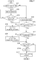
- FIG. 7 shows, as an example, a flowchart regarding health monitoring for the first electric hydraulic pump 31 and the second electric hydraulic pump 32 by the controller 9 in the EHA system 100.
- Step S71 after start, the controller 9 determines whether or not the ambient temperature is lower than the predetermined temperature. In the case of YES in determination in Step S71, the process proceeds to Step S72. In the case of NO in determination in Step S71, the process proceeds to Step S74.
- Step S72 the controller 9 performs, as described above, the warm-up operation of the EHA system 100.
- Step S73 the controller 9 determines, based on the measurement signal of the temperature sensor 84, whether or not the temperature of hydraulic fluid has increased to the predetermined temperature. In the case of NO in determination in Step S73, the process returns to Step S72, and the controller 9 continuously performs the warm-up operation of the EHA system 100. On the other hand, in the case of YES in determination in Step S73, the process proceeds to Step S74.
- Step S74 the controller 9 performs health monitoring for the first electric hydraulic pump 31 and the second electric hydraulic pump 32. Even in the case of not performing the warm-up operation, the controller 9 performs, before leg lifting control, health monitoring for the first electric hydraulic pump 31 and the second electric hydraulic pump 32 by means of the warm-up circuit 103.
- Step S75 the controller 9 determines whether or not health monitoring for the first electric hydraulic pump 31 has been completed. In the case of YES in determination in Step S75, the process proceeds to Step S77. On the other hand, in the case of NO in determination in Step S75, the process proceeds to Step S76.
- Step S76 the controller 9 operates, according to the above-described steps, only the first electric hydraulic pump 31, and calculates the volumetric efficiency ⁇ v of the first electric hydraulic pump 31. Thereafter, the process proceeds to Step S77.
- Step S77 the controller 9 determines whether or not health monitoring for the second electric hydraulic pump 32 has been completed. In the case of YES in determination in Step S77, the process proceeds to Step S79. On the other hand, in the case of NO in determination in Step S77, the process proceeds to Step S78.
- Step S78 the controller 9 operates, according to the above-described steps, only the second electric hydraulic pump 32, and calculates the volumetric efficiency ⁇ v of the second electric hydraulic pump 32. Thereafter, the process proceeds to Step S79.
- Step S79 the controller 9 determines, based on the calculated volumetric efficiencies ⁇ v , whether or not a notification needs to be made. In a case where it is determined that the notification needs to be made, the process proceeds to Step S710, the controller 9 makes the notification through a notification unit 311. In a case where it is determined that the notification does not need to be made, the process proceeds to Step S711 without proceeding to Step S710.
- Step S711 the controller 9 performs the leg lifting/lowering control.
- the leg is lifted or lowered.
- the EHA system 100 also performs health monitoring for the first electric hydraulic pump 31 and the second electric hydraulic pump 32. Based on such a health monitoring result, an administrator of the aircraft can predict a timing of requiring replacement or repairment of the first electric hydraulic pump 31 and/or the second electric hydraulic pump 32. The aircraft equipped with the EHA system 100 can reduce influence on an operation schedule to the minimum.
- EHA system 100 electric flow rate sensors for measuring the actual discharge flow rates of the first electric hydraulic pump 31 and the second electric hydraulic pump 32 are not required.
- the configuration of the EHA system 100 is simplified. Moreover, since the additional sensors are not attached, degradation of the reliability of the EHA system 100 can be reduced.
- the controller 9 can perform health monitoring with the hydraulic fluid temperature increased. The accuracy of health monitoring is improved.
- EHA systems 10, 100 shown in FIGS. 2 and 5 are examples.
- An optional circuit configuration can be employed as the circuit forming the EHA system for lifting or lowering the leg.
Landscapes
- Engineering & Computer Science (AREA)
- Mechanical Engineering (AREA)
- General Engineering & Computer Science (AREA)
- Aviation & Aerospace Engineering (AREA)
- Physics & Mathematics (AREA)
- Fluid Mechanics (AREA)
- Fluid-Pressure Circuits (AREA)
- Control Of Positive-Displacement Pumps (AREA)
Abstract
Description
- The technique disclosed herein relates to an electro hydrostatic actuator (EHA) system for lifting or lowering a leg of an aircraft.
-
Patent Document 1 describes an EHA system configured to lift or lower a leg of an aircraft. The EHA system includes a hydraulic actuator and an electric hydraulic pump. The electric hydraulic pump supplies hydraulic fluid to the hydraulic actuator. The hydraulic actuator to which hydraulic fluid has been supplied lifts or lowers the leg. With the EHA system, use of a conventional hydraulic system mounted on an aircraft can be stopped. The EHA system is advantageous in improvement in fuel consumption of the aircraft. - PATENT DOCUMENT 1:
Japanese Unexamined Patent Publication No. 2014-132189 - In some cases, the performance of the electric hydraulic pump is degraded due to breakdown or aging. As the performance of the electric hydraulic pump is degraded, a time required for leg lifting or lowering increases. The EHA system determines that the electric hydraulic pump has been broken down when the time required for leg lifting or lowering exceeds a limit time.
- The broken electric hydraulic pump needs to be replaced or repaired. Use of the aircraft needs to be stopped for replacement or repairment of the electric hydraulic pump, and for this reason, a use schedule for the aircraft is influenced.
- For example, if the EHA system can monitor the performance of the electric hydraulic pump before it is determined that the electric hydraulic pump has been broken down, a timing of requiring replacement or repairment of the electric hydraulic pump can be predicted. If the timing of requiring replacement or repairment of the electric hydraulic pump can be predicted, the influence on the operation schedule for the aircraft can be reduced to the minimum.
- However, for the EHA system configured to lift or lower the leg of the aircraft, a technique regarding health monitoring for the electric hydraulic pump has not been achieved so far.
- The technique disclosed herein achieves health monitoring for the electric hydraulic pump in the EHA system for lifting or lowering the leg.
- The technique disclosed herein relates to an EHA system for lifting or lowering a leg of an aircraft. The EHA system includes
- a hydraulic circuit including a hydraulic actuator attached to the leg to lift or lower the leg, at least one electric hydraulic pump configured to discharge hydraulic fluid supplied to the hydraulic actuator, and a hydraulic path connecting the hydraulic actuator and the electric hydraulic pump to each other,
- a pressure sensor configured to output a measurement signal corresponding to the pressure of hydraulic fluid in the hydraulic circuit during operation of the electric hydraulic pump,
- a temperature sensor configured to output a measurement signal corresponding to the temperature of hydraulic fluid, and
- a control unit configured to output a control signal for operating the electric hydraulic pump to the electric hydraulic pump,
- the hydraulic circuit including a pressure increasing element configured to increase the pressure of hydraulic fluid discharged from the electric hydraulic pump, and
- the control unit performing health monitoring regarding the performance of the electric hydraulic pump based on the pressure of hydraulic fluid based on the measurement signal of the pressure sensor, the temperature of hydraulic fluid based on the measurement signal of the temperature sensor, and the speed of the electric hydraulic pump during operation of the electric hydraulic pump.
- According to this configuration, the control unit operates the electric hydraulic pump in leg lifting or lowering, for example. For example, the control unit may perform, based on the measurement signal of the pressure sensor, feedback control such that the discharge pressure of the electric hydraulic pump reaches a target pressure. In feedback control, the control unit uses the speed of the electric hydraulic pump and the temperature of hydraulic fluid associated with the viscosity of hydraulic fluid.
- The control unit performs health monitoring regarding the performance of the electric hydraulic pump based on the pressure of hydraulic fluid based on the measurement signal of the pressure sensor, the temperature of hydraulic fluid based on the measurement signal of the temperature sensor, and the speed of the electric hydraulic pump. Note that the speed of the electric hydraulic pump can be acquired based on the control signal output from the control unit to the electric hydraulic pump.
- An administrator of the aircraft can predict, based on a health monitoring result, a timing of requiring replacement or repairment of the electric hydraulic pump. Since the timing of requiring replacement or repairment of the electric hydraulic pump can be predicted, the administrator of the aircraft can determine, in advance, a timing of stopping use of the aircraft for replacement or repairment of the electric hydraulic pump. The aircraft equipped with the EHA system can perform health monitoring for the electric hydraulic pump, and therefore, influence on an operation schedule can be reduced to the minimum.
- Even without attaching a flow rate sensor configured to measure the discharge flow rate of the electric hydraulic pump to the hydraulic circuit, the control unit can diagnose the performance of the electric hydraulic pump. The configuration of the EHA system is simplified. Since the sensor which is not always required for feedback control is not added to the EHA system, degradation of the reliability of the EHA system can be reduced.
- The pressure increasing element may be the hydraulic actuator, and
the control unit may - calculate the actual discharge flow rate of the electric hydraulic pump based on the pressure of hydraulic fluid, the temperature of hydraulic fluid, and the speed of the electric hydraulic pump during leg lifting by the hydraulic actuator, a time required for leg lifting by the hydraulic actuator, and the amount of hydraulic fluid required for leg lifting by the hydraulic actuator, and
- calculate the volumetric efficiency of the electric hydraulic pump from the calculated actual discharge flow rate and the ideal discharge flow rate of the electric hydraulic pump determined from the speed of the electric hydraulic pump.
- The amount of hydraulic fluid required for leg lifting by the hydraulic actuator is a known value. With this value, the control unit can calculate the actual discharge flow rate of the electric hydraulic pump based on the pressure of hydraulic fluid, the temperature of hydraulic fluid, the speed of the electric hydraulic pump, and the time required for leg lifting by the hydraulic actuator. Specifically, the actual discharge flow rate Q of the electric hydraulic pump can be calculated according to Expression (1-1) below.

- In this expression, Vth is the ideal discharge flow rate of the electric hydraulic pump per rotation, and is a known value determined from the specifications of the electric hydraulic pump. ω is the speed of the electric hydraulic pump. Vth·ω is the ideal discharge flow rate of the electric hydraulic pump.
- ΔP is a difference between the outlet pressure and the inlet pressure of the electric hydraulic pump. T is the temperature of hydraulic fluid. α is a coefficient regarding leakage inside the electric hydraulic pump, and is an unknown value. The actual discharge flow rate Q of the electric hydraulic pump is equivalent to a value obtained in such a manner that the leakage loss of the electric hydraulic pump is subtracted from the ideal discharge flow rate of the electric hydraulic pump.
- There is a relationship of Expression (1-2) between the actual discharge flow rate Q of the electric hydraulic pump and the amount Vact of hydraulic fluid required for leg lifting by the hydraulic actuator.

- In this expression, t1 is the time required for leg lifting by the hydraulic actuator. The control unit can calculate the actual discharge flow rate Q of the electric hydraulic pump according to Expression (1-2).
- The leakage loss of the electric hydraulic pump increases due to breakdown or aging. As the leakage loss of the electric hydraulic pump increases, a volumetric efficiency ηv decreases. As the volumetric efficiency ηv of the electric hydraulic pump decreases, the time required for leg lifting or lowering increases. When the time required for leg lifting or lowering exceeds a preset limit time, the electric hydraulic pump needs to be replaced or repaired. The volumetric efficiency is one of parameters indicating the performance of the electric hydraulic pump.
- The volumetric efficiency of the electric hydraulic pump can be calculated according to Expression (1-3) below.

- With the calculated actual discharge flow rate Q of the electric hydraulic pump, the control unit can calculate the volumetric efficiency ηv of the electric hydraulic pump according to Expression (1-3). With the volumetric efficiency ηv of the electric hydraulic pump, an administrator of the aircraft can predict a timing of replacement or repairment of the electric hydraulic pump.
- According to the above-described configuration, the EHA system can perform health monitoring for the electric hydraulic pump based on the measurement signals of the pressure and temperature sensors etc. required for feedback control for the electric hydraulic pump.
- The hydraulic actuator may be an extendable hydraulic cylinder.
- For the extendable hydraulic cylinder, the amount of hydraulic fluid required for leg lifting is determined from a cylinder volume.
- The hydraulic circuit may include a warm-up circuit in which hydraulic fluid circulates with bypassing the hydraulic actuator,
- the pressure increasing element may be a restrictor provided in the middle of the warm-up circuit and configured to increase the temperature of hydraulic fluid, and
- the control unit may
- calculate the actual discharge flow rate of the electric hydraulic pump based on the flow rate, which is determined from the pressure of hydraulic fluid and the temperature of hydraulic fluid, of hydraulic fluid passing through the restrictor during circulation of hydraulic fluid in the warm-up circuit, and
- calculate the volumetric efficiency of the electric hydraulic pump from the calculated actual discharge flow rate and the ideal discharge flow rate of the electric hydraulic pump determined from the speed of the electric hydraulic pump.
- Since the restrictor is provided in the middle of the warm-up circuit, the temperature of hydraulic fluid gradually increases when hydraulic fluid circulates in the warm-up circuit. The restrictor may be an orifice, for example.
- With the upstream and downstream pressures of the restrictor based on the measurement signal of the pressure sensor, the flow rate Qori of hydraulic fluid passing through the restrictor can be calculated. Since hydraulic fluid circulates in the warm-up circuit, the actual discharge flow rate of the electric hydraulic pump and the flow rate of hydraulic fluid passing through the restrictor are coincident with or substantially coincident with each other. The control unit calculates the actual discharge flow rate Q of the electric hydraulic pump based on the flow rate, which is determined from the pressure of hydraulic fluid and the temperature of hydraulic fluid, of hydraulic fluid passing through the restrictor during circulation of hydraulic fluid in the warm-up circuit.
- Specifically, the flow rate Qori of hydraulic fluid passing through the restrictor can be calculated according to Expression (1-4) below.

- In this expression, CD is the flow coefficient of the restrictor. A is the passage area of the restrictor. ρ is the density of hydraulic fluid, and the density of hydraulic fluid is the function of the temperature of hydraulic fluid. ΔP is a difference between the upstream and downstream pressures of the restrictor, and in the warm-up circuit, corresponds to the difference between the outlet pressure and the inlet pressure of the electric hydraulic pump.
- With the calculated actual discharge flow rate Q of the electric hydraulic pump, the control unit can calculate the volumetric efficiency ηv of the electric hydraulic pump according to Expression (1-3). With the volumetric efficiency ηv of the electric hydraulic pump, the administrator of the aircraft can predict the timing of replacement or repairment of the electric hydraulic pump.
- The EHA system with this configuration can also perform health monitoring for the electric hydraulic pump without the need for attaching a flow rate sensor configured to measure the actual discharge flow rate of the electric hydraulic pump to the hydraulic circuit.
- The electric hydraulic pump may include a first electric hydraulic pump and a second electric hydraulic pump,
- the first electric hydraulic pump and the second electric hydraulic pump may be connected in parallel with the hydraulic actuator, and
- the control unit may cause hydraulic fluid to circulate in the warm-up circuit by operating only the first electric hydraulic pump to perform health monitoring for the first electric hydraulic pump, and cause hydraulic fluid to circulate in the warm-up circuit by operating only the second electric hydraulic pump to perform health monitoring for the second electric hydraulic pump.
- In a case where two electric hydraulic pumps, i.e., the first electric hydraulic pump and the second electric hydraulic pump, are operated, the control unit cannot perform health monitoring for each of the first electric hydraulic pump and the second electric hydraulic pump.
- For this reason, the control unit performs health monitoring for the first electric hydraulic pump by operating only the first electric hydraulic pump. Moreover, the control unit performs health monitoring for the second electric hydraulic pump by operating only the second electric hydraulic pump. The electric hydraulic pumps are operated one by one, and therefore, the control unit can perform health monitoring for each of the first electric hydraulic pump and the second electric hydraulic pump.
- The control unit may
- perform a warm-up operation of causing hydraulic fluid to circulate in the warm-up circuit by operating both the first electric hydraulic pump and the second electric hydraulic pump, and
- after the warm-up operation, perform health monitoring for the first electric hydraulic pump by operating only the first electric hydraulic pump and perform health monitoring for the second electric hydraulic pump by operating only the second electric hydraulic pump.
- With this configuration, both the first electric hydraulic pump and the second electric hydraulic pump are operated so that the EHA system can promptly complete the warm-up operation. Before leg lifting or lowering and after completion of the warm-up operation, the EHA system can perform health monitoring for the first electric hydraulic pump and health monitoring for the second electric hydraulic pump. The temperature of hydraulic fluid is high in health monitoring, and therefore, the control unit can accurately execute health monitoring for the first electric hydraulic pump and health monitoring for the second electric hydraulic pump.
- The EHA system may further include a notification unit configured to notify a result of health monitoring for the electric hydraulic pump in response to a control signal from the control unit.
- With this configuration, the administrator of the aircraft can predict the timing of replacement or repairment of the electric hydraulic pump based on the notification from the notification unit.
- The control unit may determine that the electric hydraulic pump is broken down in a case where a time until completion after the start of leg lifting exceeds a preset limit time.
- With this configuration, the EHA system can diagnose breakdown of the electric hydraulic pump in addition to health monitoring for the electric hydraulic pump. The administrator of the aircraft can execute replacement or repairment of the electric hydraulic pump at a proper timing.
- As described above, the EHA system for lifting or lowering the leg as disclosed herein can perform health monitoring for the electric hydraulic pump.
-
- [
FIG. 1] FIG. 1 is a perspective view showing, as an example, a landing gear of an aircraft. - [
FIG. 2] FIG. 2 is a circuit diagram showing, as an example, an EHA system for lifting or lowering a leg. - [
FIG. 3] FIG. 3 is a diagram showing a state when the EHA system ofFIG. 2 lifts the leg. - [
FIG. 4] FIG. 4 is a flowchart regarding health monitoring for an electric hydraulic pump in the EHA system ofFIG. 2 . - [
FIG. 5] FIG. 5 is a circuit diagram of an EHA system having a configuration different from that ofFIG. 2 . - [
FIG. 6] FIG. 6 is a diagram showing a state in which the EHA system ofFIG. 5 performs warm-up operation. - [
FIG. 7] FIG. 7 is a flowchart regarding health monitoring for an electric hydraulic pump in the EHA system ofFIG. 5 . - Hereinafter, an embodiment of an EHA system for lifting or lowering a leg of an aircraft will be described with reference to the drawings. The EHA system described below is an example.
FIG. 1 is a view showing an example of alanding gear 1 of the aircraft. Thelanding gear 1 is a main leg. - The
landing gear 1 retracts aleg 11 in anairframe 12 and deploys theleg 11 from theairframe 12.Wheels 15 are attached to a distal end of theleg 11. Thelanding gear 1 has agear cylinder 21, adoor cylinder 22, a down-lock release cylinder 23, a door up-lock release cylinder 26, and a gear up-lock release cylinder 27. - The
gear cylinder 21 lifts or lowers theleg 11. Thedoor cylinder 22 opens or closes adoor 14 of abay 13. Thebay 13 houses theleg 11. The down-lock release cylinder 23 releases a down-lock mechanism configured to fix a leg-lowered state. The door up-lock release cylinder 26 releases a door up-lock mechanism configured to fix the door in a lifted state. The gear up-lock release cylinder 27 releases a gear up-lock mechanism configured to fix theleg 11 in a lifted state. Each of thecylinders cylinders landing gear 1 may have only some of these cylinders. -
FIG. 2 is a circuit diagram showing a first configuration example of the EHA system for thelanding gear 1. Note that inFIG. 2 , a hydraulic path is indicated by a solid line, a pilot hydraulic path is indicated by a dashed line, and an electric signal path is indicated by a chain double-dashed line. - The
EHA system 10 of the first configuration example includes ahydraulic circuit 101. Thehydraulic circuit 101 includes a hydraulic actuator, an electric hydraulic pump, and the hydraulic path. The hydraulic path connects the hydraulic actuator and the electric hydraulic pump to each other. - The hydraulic actuator includes the
gear cylinder 21, thedoor cylinder 22, and the down-lock release cylinder 23 as described above. TheEHA system 10 may include the door up-lock release cylinder 26 and the gear up-lock release cylinder 27. Alternatively, theEHA system 10 may include only some of thesecylinders gear cylinder 21, thedoor cylinder 22, and the down-lock release cylinder 23 will be collectively referred to as ahydraulic cylinder 2. - The
hydraulic cylinder 2 has a bore-side fluid chamber 24 and an annulus-side fluid chamber 25. In the cylinder, a piston head separates the bore-side fluid chamber 24 and the annulus-side fluid chamber 25 from each other. Of thehydraulic cylinder 2, a first port communicates with the bore-side fluid chamber 24, and a second port communicates with the annulus-side fluid chamber 25. Hydraulic fluid flows into or out of the bore-side fluid chamber 24 through the first port, and flows into or out of the annulus-side fluid chamber 25 through the second port. - In the configuration example of
FIG. 2 , thegear cylinder 21 lifts theleg 11 against a load upon extension, and releases the load and lowers theleg 11 upon contraction. In the configuration example ofFIG. 2 , thedoor cylinder 22 releases a load and opens the door upon extension, and closes the door against the load upon contraction. In the configuration example ofFIG. 2 , a not-shown biasing member applies a load to the down-lock release cylinder 23 in an extending direction. By contraction, the down-lock release cylinder 23 releases the mechanism configured to fix the leg-lowered state. Note that the configurations of thegear cylinder 21, thedoor cylinder 22, and the down-lock release cylinder 23 are not limited to the above-described configurations. - The
EHA system 10 includes the electrichydraulic pump 3. The electrichydraulic pump 3 supplies hydraulic fluid to eachhydraulic cylinder 2. - The electric
hydraulic pump 3 includes a singlehydraulic pump 33 and a singleelectric motor 34. Thehydraulic pump 33 and theelectric motor 34 are coupled to each other. Thehydraulic pump 33 is, in this configuration example, of a one-way rotation type which is rotatable only in one direction. Thehydraulic pump 33 may be, for example, a gear pump. Note that the type ofhydraulic pump 33 is not limited to above. Theelectric motor 34 is activated, operated, or stopped in response to a control signal from a later-describedcontroller 9. - The hydraulic path downstream of the electric
hydraulic pump 3 is branched. This branched path is connected to areservoir tank 81 through arelief valve 36 and afilter 82. - The
reservoir tank 81 absorbs fluctuation in the total volume of the bore-side fluid chamber 24 and the annulus-side fluid chamber 25 of thehydraulic cylinder 2 due to extension or contraction of thehydraulic cylinder 2. A suction port of the electrichydraulic pump 3 is connected to thereservoir tank 81. - Moreover, a
first pressure sensor 83 is attached to thereservoir tank 81. Thefirst pressure sensor 83 outputs, to the later-describedcontroller 9, a measurement signal corresponding to the pressure of hydraulic fluid in thereservoir tank 81. The pressure based on the measurement signal of thefirst pressure sensor 83 is equivalent to the inlet pressure of the electrichydraulic pump 3. - A
temperature sensor 84 is attached to thereservoir tank 81. Thetemperature sensor 84 outputs, to thecontroller 9, a measurement signal corresponding to the temperature of hydraulic fluid in thereservoir tank 81. The temperature of hydraulic fluid changes according to environment around the aircraft. - A
second pressure sensor 38 is attached to the path branched from the electrichydraulic pump 3. Thesecond pressure sensor 38 outputs, to thecontroller 9, a measurement signal corresponding to the discharge pressure (i.e., the outlet pressure) of the electrichydraulic pump 3. A difference between the pressure based on thesecond pressure sensor 38 and the pressure based on thefirst pressure sensor 83 is equivalent to a difference between the outlet pressure and the inlet pressure of the electrichydraulic pump 3. - A discharge port of the electric
hydraulic pump 3 is connected to agear selector valve 41 and adoor selector valve 42. - The
gear selector valve 41 is a four-port three-position switching valve having four ports including a P port, a T port, an A port, and a B port. Thegear selector valve 41 selectively supplies hydraulic fluid to thegear cylinder 21 and the down-lock release cylinder 23. The P port is connected to the discharge port of the electrichydraulic pump 3. The T port is connected to thereservoir tank 81. The A port is connected to each of the bore-side fluid chamber 24 of thegear cylinder 21 and the annulus-side fluid chamber 25 of the down-lock release cylinder 23. The B port is connected to the annulus-side fluid chamber 25 of thegear cylinder 21. Note that the bore-side fluid chamber 24 of the down-lock release cylinder 23 is connected to thereservoir tank 81. - Moreover, the
gear selector valve 41 is a hydraulic pilot solenoid valve. A spool receives a pilot hydraulic pressure. The spool is biased to a center position by a spring. Thegear selector valve 41 causes, at the center position, each of the A port and the B port to communicate with the T port. At a first offset position (i.e., a position on the left side inFIG. 2 ), thegear selector valve 41 causes the A port and the P port to communicate with each other, and causes the B port and the T port to communicate with each other. At a second offset position (i.e., a position on the right side inFIG. 2 ), thegear selector valve 41 causes the A port and the T port to communicate with each other, and causes the B port and the T port to communicate with each other. By switching of thegear selector valve 41, thecontroller 9 selectively supplies hydraulic fluid to the bore-side fluid chamber 24 or the annulus-side fluid chamber 25 of thegear cylinder 21, and switches a supply of hydraulic fluid to the annulus-side fluid chamber 25 of the down-lock release cylinder 23 between a supply state and a stop state. - A
speed control valve 44 is interposed between the A port of thegear selector valve 41 and the bore-side fluid chamber 24 of thegear cylinder 21. Thespeed control valve 44 is configured such that a check valve and an orifice are provided in parallel. Thespeed control valve 44 adjusts the speed of contraction of thegear cylinder 21. - The
door selector valve 42 is a four-port two-position switching valve having four ports including a P port, a T port, an A port, and a B port. Thedoor selector valve 42 selectively supplies hydraulic fluid to thedoor cylinder 22. The P port is connected to the discharge port of the electrichydraulic pump 3. The T port is connected to thereservoir tank 81. The A port is connected to the bore-side fluid chamber 24 of thedoor cylinder 22. The B port is connected to the annulus-side fluid chamber 25 of thedoor cylinder 22. - The
door selector valve 42 is also a hydraulic pilot solenoid valve. A spool receives a pilot hydraulic pressure. The spool is biased to a normal position by a spring. Thedoor selector valve 42 causes, at the normal position, each of the A port and the B port to communicate with the P port. At an offset position, thedoor selector valve 42 causes the A port and the T port to communicate with each other, and causes the B port and the P port to communicate with each other. By switching of thedoor selector valve 42, thecontroller 9 selectively supplies hydraulic fluid to the bore-side fluid chamber 24 or the annulus-side fluid chamber 25 of thedoor cylinder 22. - A
speed control valve 45 is interposed between the B port of thedoor selector valve 42 and the annulus-side fluid chamber 25 of thedoor cylinder 22. Thespeed control valve 45 is configured such that a check valve and an orifice are provided in parallel. Thespeed control valve 45 adjusts the speed of extension of thedoor cylinder 22. - A
dump valve 43 is interposed among thegear cylinder 21, thedoor cylinder 22, and thereservoir tank 81. Thedump valve 43 is a five-port two-position switching valve having A, B, C, and D ports and a T port. The A port of thedump valve 43 is connected to the annulus-side fluid chamber 25 of thegear cylinder 21. The B port is connected to the bore-side fluid chamber 24 of thegear cylinder 21. The C port is connected to the annulus-side fluid chamber 25 of thedoor cylinder 22. The D port is connected to the bore-side fluid chamber 24 of thedoor cylinder 22. The T port is connected to thereservoir tank 81. - The
dump valve 43 is a solenoid valve including a spool to be directly driven by a solenoid. The spool is biased to a normal position by a spring. At the normal position, thedump valve 43 causes all of the A, B, C, and D ports to communicate with the T port. At an offset position, thedump valve 43 disconnects each of the A to D ports from the T port. Thecontroller 9 switches thedump valve 43. - A
reference character 310 inFIG. 2 indicates a sensor configured to sense operation of thelanding gear 1. Thesensor 310 may be, for example, a limit switch attached to thegear cylinder 21. The limit switch outputs a signal to thecontroller 9 in each of a case where thegear cylinder 21 is in an extended state and a case where thegear cylinder 21 is in a contracted state. - A
reference character 311 inFIG. 2 indicates a notification unit configured to notify a pilot or a mechanic of a later-described health monitoring result. - Next, operation of the
EHA system 10 in leg lifting will be described. When retracting theleg 11 in theairframe 12, thelanding gear 1 performs an operation of opening the closed door, lifting the leg, and closing the door after completion of leg lifting. When deploying theleg 11 from theairframe 12, thelanding gear 1 performs an operation of opening the closed door, lowering the leg, and closing the door after completion of leg lowering. - The
controller 9 outputs a control signal to the electrichydraulic pump 3. The electrichydraulic pump 3 is activated, operated, or stopped in response to the control signal. Thecontroller 9 also outputs control signals to thegear selector valve 41, thedoor selector valve 42, and thedump valve 43. Thegear selector valve 41, thedoor selector valve 42, and thedump valve 43 switch the positions of the spools in response to the control signals. Thecontroller 9 outputs the control signals to the electrichydraulic pump 3, thegear selector valve 41, thedoor selector valve 42, and thedump valve 43 so that theleg 11 can be retracted in theleg 11 or be deployed from theairframe 12. Thecontroller 9 is an example of a control unit. -
FIG. 3 shows operation of theEHA system 10 when the door is opened and the leg is lifted. Note thatFIG. 3 does not show thecontroller 9, theelectric motor 34, and the electric signal path. Moreover, inFIG. 3 , the hydraulic path in which hydraulic fluid is supplied is indicated by a thick solid line, the pilot hydraulic path is indicated by a dashed line, and the hydraulic path connected to thereservoir tank 81 is indicated by a thin solid line. - The
controller 9 switches thegear selector valve 41 to the first offset position. The A port and the P port of thegear selector valve 41 communicate with each other, and the B port and the T port of thegear selector valve 41 communicate with each other. Moreover, thecontroller 9 operates the electrichydraulic pump 3. Thecontroller 9 feedback-controls the electrichydraulic pump 3 based on the measurement signal of thesecond pressure sensor 38. The discharge pressure of the electrichydraulic pump 3 is coincident with or substantially coincident with a target pressure. - As indicated by arrows in this figure, hydraulic fluid is supplied to the annulus-
side fluid chamber 25 of the down-lock release cylinder 23 through thegear selector valve 41. The down-lock release cylinder 23 is contracted as indicated by an arrow inFIG. 3 . The mechanism configured to fix the leg-lowered state is released. Moreover, hydraulic fluid is supplied to the bore-side fluid chamber 24 of thegear cylinder 21 through thegear selector valve 41. Thegear cylinder 21 is extended as indicated by an arrow inFIG. 3 . Accordingly, theleg 11 is lifted. Note that hydraulic fluid discharged from the annulus-side fluid chamber 25 by extension of thegear cylinder 21 returns to thereservoir tank 81 through thegear selector valve 41 and thefilter 82. Thecontroller 9 determines, based on a detection signal of thesensor 310, that leg lifting has been completed. - Hereinafter, health monitoring for the electric
hydraulic pump 3 by theEHA system 10 will be described. TheEHA system 10 performs health monitoring regarding the performance of the electrichydraulic pump 3. More specifically, theEHA system 10 monitors the volumetric efficiency of the electrichydraulic pump 3. - The volumetric efficiency ηv of the electric
hydraulic pump 3 can be calculated according to Expression (2-1) below.

- In this expression, Q is the actual discharge flow rate of the electric
hydraulic pump 3. Vth is the discharge flow rate (ideal) of the electrichydraulic pump 3 per rotation, and is a known value determined from the specifications of the electrichydraulic pump 3. Vth is, for example, stored in a memory of thecontroller 9. ω is the speed of the electrichydraulic pump 3. Vth·ω is the ideal discharge flow rate of the electrichydraulic pump 3. The speed of the electrichydraulic pump 3 can be, for example, calculated based on the control signal output from thecontroller 9 to the electrichydraulic pump 3. - The actual discharge flow rate Q of the electric
hydraulic pump 3 is equivalent to a value obtained in such a manner that the leakage loss of the electrichydraulic pump 3 is subtracted from the ideal discharge flow rate of the electrichydraulic pump 3. The leakage loss of the electrichydraulic pump 3 increases due to breakdown or aging. As the leakage loss of the electrichydraulic pump 3 increases, the volumetric efficiency ηv decreases. As the volumetric efficiency ηv of the electrichydraulic pump 3 decreases, a time required for leg lifting or lowering increases. When the time required for leg lifting or lowering exceeds a preset limit time, the electrichydraulic pump 3 needs to be replaced or repaired. The volumetric efficiency ηv of the electrichydraulic pump 3 is one of parameters indicating the performance of the electrichydraulic pump 3. - The actual discharge flow rate Q of the electric
hydraulic pump 3 can be calculated according to Expression (2-2) below.

ΔP is the difference between the outlet pressure and the inlet pressure of the electrichydraulic pump 3. T is the temperature of hydraulic fluid. α is a coefficient regarding leakage inside the electrichydraulic pump 3, and is an unknown value. - Moreover, the actual discharge flow rate Q of the electric
hydraulic pump 3 can be represented by Expression (2-3) below by means of a hydraulic fluid amount Vact required for operation of thehydraulic cylinder 2.

- In this expression, t1 is a time until completion after the start of operation of the
hydraulic cylinder 2, i.e., a time until stop after the start of operation of the electrichydraulic pump 3. - The hydraulic fluid amount Vact required for operation of the
hydraulic cylinder 2 is fixed from the volume of thehydraulic cylinder 2. Thehydraulic cylinder 2 may be, for example, thegear cylinder 21. The hydraulic fluid amount Vact required for operation of thehydraulic cylinder 2 may be a hydraulic fluid amount required for thegear cylinder 21 for lifting the leg. The hydraulic fluid amount Vact is, for example, stored in the memory of thecontroller 9. - The
first pressure sensor 83 outputs the measurement signal corresponding to the inlet pressure of the electrichydraulic pump 3. Thesecond pressure sensor 38 outputs the measurement signal corresponding to the outlet pressure of the electrichydraulic pump 3. Thefirst pressure sensor 83 outputs the measurement signal corresponding to the temperature of hydraulic fluid. - Based on the measurement signals of the
first pressure sensor 83, thesecond pressure sensor 38, and thetemperature sensor 84 and the time t1 required for leg lifting during leg lifting by thegear cylinder 21 by a supply of hydraulic fluid from the electrichydraulic pump 3, thecontroller 9 performs arithmetic operation according to Expressions (2-1) to (2-3) above, thereby calculating the volumetric efficiency ηv of the electrichydraulic pump 3. - For example, when the calculated volumetric efficiency ηv falls below a preset limit value, the
controller 9 notifies the pilot and/or the mechanic of the aircraft of such a situation through thenotification unit 311. Accordingly, an administrator of the aircraft can predict a timing of requiring replacement or repairment of the electrichydraulic pump 3. - The
controller 9 may make a notification through thenotification unit 311 based on the history of a change in the calculated volumetric efficiency ηv. The history of the change in the volumetric efficiency ηv indicates the speed of progression of deterioration of the electrichydraulic pump 3. Based on the speed of progression of deterioration of the electrichydraulic pump 3, the administrator of the aircraft can more accurately predict the timing of requiring replacement or repairment of the electrichydraulic pump 3. - Note that health monitoring using leg lifting by the
gear cylinder 21 has been described as an example, but thecontroller 9 may also perform health monitoring for the electrichydraulic pump 3 by means of operation of thedoor cylinder 22 or operation of the down-lock release cylinder 23. -
FIG. 4 shows, as an example, a flowchart regarding health monitoring for the electrichydraulic pump 3 by thecontroller 9. First, in Step S11 after start, thecontroller 9 determines whether or not the leg is to be lifted. In the case of NO in determination in Step S11, Step S11 is repeated in the process. In the case of YES in determination in Step S11, the process proceeds to Step S12. - In Step S12, the
controller 9 starts operation of the electrichydraulic pump 3. Hydraulic fluid is supplied to thegear cylinder 21, and theleg 11 is lifted accordingly. In Step S13, thecontroller 9 determines, based on the detection signal of thesensor 310, whether or not leg lifting has been completed. In the case of NO in determination in Step S13, the process returns to Step S12, and operation of the electrichydraulic pump 3 is continued. In the case of YES in determination in Step S13, the process proceeds to Step S14, and thecontroller 9 stops operation of the electrichydraulic pump 3. Thecontroller 9 measures the time t1 required for leg lifting from Step S12 to Step S14. Moreover, thecontroller 9 stores the difference ΔP between the outlet pressure and the inlet pressure of the electrichydraulic pump 3 based on the measurement signals of thefirst pressure sensor 83 and thesecond pressure sensor 38, the temperature T of hydraulic fluid based on the measurement signal of thetemperature sensor 84, and the speed ω of the electrichydraulic pump 3. - In Step S15, the
controller 9 determines whether or not the time t1 required for leg lifting is within the preset limit time, i.e., whether or not the time t1 required for leg lifting is shorter. In a case where the time required for leg lifting is within the limit time, the process proceeds to Step S16. In a case where the time required for leg lifting exceeds the limit time, the process proceeds to Step S19. - In Step S19, the
controller 9 determines that the electrichydraulic pump 3 has been broken down. Thecontroller 9 notifies the pilot of breakdown of the electrichydraulic pump 3 through, e.g., thenotification unit 311. - In Step S16, the
controller 9 executes health monitoring for the electrichydraulic pump 3. Specifically, based on the difference ΔP between the outlet pressure and the inlet pressure of the electrichydraulic pump 3, the temperature T of hydraulic fluid, and the speed ω of the electrichydraulic pump 3 measured in leg lifting and the time t1 required for leg lifting, the volumetric efficiency ηv of the electrichydraulic pump 3 is calculated according to Expressions (2-1) to (2-3). - Subsequently, in Step S17, the
controller 9 determines, based on the calculated volumetric efficiency ηv, whether or not a notification needs to be made. In a case where it is determined that the notification needs to be made, the process proceeds to Step S18, and thecontroller 9 makes the notification through thenotification unit 311. In a case where it is determined that the notification does not need to be made, the process returns without proceeding to Step S18. - As described above, the
EHA system 10 performs health monitoring for the electrichydraulic pump 3. Based on the health monitoring result, the administrator of the aircraft can predict the timing of requiring replacement or repairment of the electrichydraulic pump 3. Since the timing of requiring replacement or repairment of the electrichydraulic pump 3 can be predicted, the administrator of the aircraft can determine, in advance, a timing of stopping use of the aircraft for replacement or repairment of the electrichydraulic pump 3. The aircraft equipped with theEHA system 10 can perform health monitoring for the electrichydraulic pump 3, and therefore, influence on an operation schedule can be reduced to the minimum. - The
EHA system 10 diagnoses breakdown of the electrichydraulic pump 3 in addition to health monitoring for the electrichydraulic pump 3. With this configuration, the administrator of the aircraft can execute replacement or repairment of the electrichydraulic pump 3 at a proper timing. - Even without attaching a flow rate sensor configured to measure the actual discharge flow rate of the electric
hydraulic pump 3 to thehydraulic circuit 101, thecontroller 9 can calculate the volumetric efficiency of the electrichydraulic pump 3 by means of thefirst pressure sensor 83, thesecond pressure sensor 38, and thetemperature sensor 84 used for, e.g., feedback control of the electrichydraulic pump 3. The configuration of theEHA system 10 is simplified. Moreover, since the additional sensor is not attached, degradation of the reliability of theEHA system 10 can be reduced. -
FIG. 5 shows a circuit diagram of anEHA system 100 having a configuration different from that ofFIG. 2 . Note that inFIG. 5 , a hydraulic path is indicated by a solid line and an electric signal path is indicated by a chain double-dashed line. In theEHA system 100 ofFIG. 5 , the same reference characters are used to represent the same components as those of theEHA system 10 ofFIG. 2 . TheEHA system 100 includes ahydraulic circuit 102. - The
EHA system 100 ofFIG. 5 has two pumps including a first electrichydraulic pump 31 and a second electrichydraulic pump 32. The first electrichydraulic pump 31 and the second electrichydraulic pump 32 are provided in parallel withhydraulic cylinders 2. Each of the first electrichydraulic pump 31 and the second electrichydraulic pump 32 supplies hydraulic fluid to eachhydraulic cylinder 2. Each electric hydraulic pump includes a single hydraulic pump and a single electric motor. - In the case of supplying hydraulic fluid to each
hydraulic cylinder 2, acontroller 9 operates both the first electrichydraulic pump 31 and the second electrichydraulic pump 32. In a case where the first electrichydraulic pump 31 is failed, thecontroller 9 operates only the second electrichydraulic pump 32. In a case where the second electrichydraulic pump 32 is failed, thecontroller 9 operates only the first electrichydraulic pump 31. TheEHA system 100 is redundant because the first electrichydraulic pump 31 and the second electrichydraulic pump 32 are provided in parallel with eachhydraulic cylinder 2. Thus, in theEHA system 100, hydraulic fluid can be supplied to eachhydraulic cylinder 2 only by the single electric hydraulic pump. - A
check valve 35 is arranged between a mergingportion 37 between the first electrichydraulic pump 31 and the second electrichydraulic pump 32 and the first electrichydraulic pump 31. Acheck valve 35 is also arranged between the mergingportion 37 and the second electrichydraulic pump 32. In a case where one of the first and second electrichydraulic pumps check valves 35 stops hydraulic fluid discharged from the other electric hydraulic pump from flowing back to the stopped electric hydraulic pump. - A
second pressure sensor 38 is provided between the first electrichydraulic pump 31 and thecheck valve 35, and anothersecond pressure sensor 38 is provided between the second electrichydraulic pump 32 and thecheck valve 35. These twosecond pressure sensors 38 output measurement signals corresponding to the discharge pressures of the first electrichydraulic pump 31 and the second electrichydraulic pump 32. - The merging
portion 37 is connected to agear selector valve 410 and adoor selector valve 420. - The
gear selector valve 410 is a four-port three-position switching valve having four ports including a P port, a T port, an A port, and a B port. Thegear selector valve 410 selectively supplies hydraulic fluid to agear cylinder 21 and a down-lock release cylinder 23. The P port is connected to the mergingportion 37. The T port is connected to areservoir tank 81. The A port is connected to each of a bore-side fluid chamber of thegear cylinder 21 and an annulus-side fluid chamber of the down-lock release cylinder 23. The B port is connected to each of an annulus-side fluid chamber of thegear cylinder 21 and a bore-side fluid chamber of the down-lock release cylinder 23. - The
gear selector valve 410 is driven by a motor. Thecontroller 9 controls operation of the motor. At a center position, thegear selector valve 410 causes the P port and the T port to communicate with each other. Thegear selector valve 410 has anorifice 411. The P port and the T port communicate with each other through theorifice 411. In the case of performing warm-up operation of theEHA system 100 as described later, thegear selector valve 410 is at the center position. Theorifice 411 is included in a later-described warm-up circuit 103. Theorifice 411 increases the temperature of hydraulic fluid circulating in the warm-up circuit 103. - At a first offset position (i.e., a position on the left side in
FIG. 5 ), thegear selector valve 410 causes the A port and the B port to communicate with the T port. The A and B ports and the T port communicate with each other through a second orifice. Thegear selector valve 410 is at the first offset position in leg lowering. At a second offset position (i.e., a position on the right side inFIG. 5 ), thegear selector valve 410 causes the A port and the P port to communicate with each other, and causes the B port and the T port to communicate with each other. Thegear selector valve 410 is at the second offset position in leg lifting. - By switching of the
gear selector valve 410, thecontroller 9 selectively supplies hydraulic fluid to the bore-side fluid chamber or the annulus-side fluid chamber of thegear cylinder 21, and selectively supplies hydraulic fluid to the bore-side fluid chamber or the annulus-side fluid chamber of the down-lock release cylinder 23. - The
door selector valve 420 is a three-port two-position switching valve having three ports including a P port, a T port, and an A port. Thedoor selector valve 420 selectively supplies hydraulic fluid to thedoor cylinder 22. The P port is connected to the mergingportion 37. The T port is connected to thereservoir tank 81. The A port is connected to a bore-side fluid chamber of thedoor cylinder 22. - The
door selector valve 420 is also driven by a motor. Thecontroller 9 controls operation of the motor. At a normal position, thedoor selector valve 420 causes the A port and the P port to communicate with each other. At an offset position, thedoor selector valve 420 causes the A port and the T port to communicate with each other. Thedoor selector valve 420 is at the normal position in door opening. Thedoor selector valve 420 is at the offset position in door closing. By switching of thedoor selector valve 420, thecontroller 9 selectively supplies hydraulic fluid to the bore-side fluid chamber or an annulus-side fluid chamber of thedoor cylinder 22. - A
dump valve 430 is interposed among thegear cylinder 21, thedoor cylinder 22, the down-lock release cylinder 23, and thereservoir tank 81. Thedump valve 430 is a three-port two-position switching valve having A and B ports and a T port. - The A port of the
dump valve 430 is connected to the bore-side fluid chamber of thegear cylinder 21 and the annulus-side fluid chamber of the down-lock release cylinder 23. - The B port is connected to the annulus-side fluid chamber of the
door cylinder 22. The B port is also connected to the P port of thegear selector valve 410, and is connected to the P port of thedoor selector valve 420. The T port is connected to thereservoir tank 81. - A
check valve 51 is provided among the bore-side fluid chamber of thedoor cylinder 22, a suction port of the first electrichydraulic pump 31, and a suction port of the second electrichydraulic pump 32. Similarly, acheck valve 52 is provided among the annulus-side fluid chamber of thegear cylinder 21, the bore-side fluid chamber of the down-lock release cylinder 23, the suction port of the first electrichydraulic pump 31, and the suction port of the second electrichydraulic pump 32. - Operation of the
EHA system 100 will be briefly described herein. Thecontroller 9 outputs control signals to the first electrichydraulic pump 31 and the second electrichydraulic pump 32. The first electrichydraulic pump 31 and the second electrichydraulic pump 32 are activated, operated, or stopped in response to the control signals. Moreover, thecontroller 9 outputs control signals to thegear selector valve 410, thedoor selector valve 420, and thedump valve 430. Thegear selector valve 410, thedoor selector valve 420, and thedump valve 430 switch spool positions in response to the control signals. Thecontroller 9 outputs the control signals to the first electrichydraulic pump 31, the second electrichydraulic pump 32, thegear selector valve 410, thedoor selector valve 420, and thedump valve 430, thereby retracting aleg 11 in anairframe 12 or deploying theleg 11 from theairframe 12. - For example, when opening a door and lifting the leg, the
controller 9 switches thegear selector valve 410 to the second offset position. Of thegear selector valve 410, the A port and the P port communicate with each other, and the B port and the T port communicate with each other. Moreover, thecontroller 9 operates the first electrichydraulic pump 31 and the second electrichydraulic pump 32. - Although not shown in the figure, hydraulic fluid is supplied to the annulus-side fluid chamber of the down-
lock release cylinder 23 through thegear selector valve 410. The down-lock release cylinder 23 is contracted. A mechanism configured to fix a leg-lowered state is released. Moreover, hydraulic fluid is supplied to the bore-side fluid chamber of thegear cylinder 21. Thegear cylinder 21 is extended. Accordingly, theleg 11 is lifted. - An aircraft takes off from a region under a low air temperature, or lands a region under a low air temperature. When a temperature around the EHA system mounted on the aircraft is low, the temperature of hydraulic fluid decreases. As the temperature of hydraulic fluid decreases, the viscosity of hydraulic fluid greatly changes.
- For this reason, the
EHA system 100 performs the warm-up operation for increasing the temperature of hydraulic fluid when the ambient temperature is low. TheEHA system 100 includes the warm-up circuit 103. -
FIG. 6 shows a state in which theEHA system 100 performs the warm-up operation. Note thatFIG. 6 does not show thecontroller 9 and the electric signal path. When performing the warm-up operation, thecontroller 9 switches thegear selector valve 410 to the center position. The P port and the T port of thegear selector valve 410 communicate with each other through theorifice 411. Accordingly, the warm-up circuit 103 is formed as indicated by a thick solid line inFIG. 6 . - The
controller 9 operates both the first electrichydraulic pump 31 and the second electrichydraulic pump 32, and accordingly, hydraulic fluid discharged from the first electrichydraulic pump 31 and the second electrichydraulic pump 32 returns to thereservoir tank 81 with bypassing eachhydraulic cylinder 2. Hydraulic fluid circulates in the warm-up circuit 103 including theorifice 411, and accordingly, the temperature of hydraulic fluid gradually increases. When the temperature of hydraulic fluid has increased to a preset temperature, thecontroller 9 ends the warm-up operation. - The
EHA system 100 includes the first electrichydraulic pump 31 and the second electrichydraulic pump 32. In the case of supplying hydraulic fluid to eachhydraulic cylinder 2, both the first electrichydraulic pump 31 and the second electrichydraulic pump 32 are operated. For example, in a state in which both the first electrichydraulic pump 31 and the second electrichydraulic pump 32 are operated, when an attempt is made to calculate the actual discharge flow rate of the first electrichydraulic pump 31 and the actual discharge flow rate of the second electrichydraulic pump 32 when hydraulic fluid is supplied to eachhydraulic cylinder 2, it is difficult to separately calculate these two discharge flow rates. - For this reason, in the
EHA system 100, thecontroller 9 performs health monitoring for each of the first electrichydraulic pump 31 and the second electrichydraulic pump 32 by means of the warm-up circuit 103. - Specifically, the
controller 9 operates only the first electrichydraulic pump 31 before leg lifting or lowering and after the end of the warm-up operation, for example. Accordingly, hydraulic fluid discharged from the first electrichydraulic pump 31 returns to thereservoir tank 81 after having passed through theorifice 411, as described above. At this point, hydraulic fluid bypasses eachhydraulic cylinder 2, and therefore, a hydraulic fluid amount Vact required for operation of thehydraulic cylinder 2 cannot be used for calculation of the actual discharge flow rate Q of the first electrichydraulic pump 31. - However, in a case where hydraulic fluid circulates in the warm-
up circuit 103, the actual discharge flow rate Q of the first electrichydraulic pump 31 is equal to or substantially equal to the flow rate Qori of hydraulic fluid passing through theorifice 411. Thus, thecontroller 9 calculates the actual discharge flow rate Q of the first electrichydraulic pump 31 by means of the flow rate Qori of hydraulic fluid passing through theorifice 411. - The flow rate Qori of hydraulic fluid passing through the
orifice 411 can be calculated according to Expression (2-4) below.

- In this expression, CD is the flow coefficient of the
orifice 411. A is the passage area of theorifice 411. ρ is the density of hydraulic fluid, and the density of hydraulic fluid is the function of the temperature of hydraulic fluid. The density ρ of hydraulic fluid can be acquired based on a measurement signal of atemperature sensor 84. ΔP is a pressure difference between upstream and downstream sides of theorifice 411. In the warm-up circuit 103, the upstream pressure of theorifice 411 is equivalent to the discharge pressure of the first electrichydraulic pump 31 or the second electrichydraulic pump 32. The downstream pressure of theorifice 411 is equivalent to the pressure of thereservoir tank 81. Thus, the pressure difference ΔP can be acquired based on the measurement signals of the twosecond pressure sensors 38 and a measurement signal of afirst pressure sensor 83. - The
controller 9 can calculate the actual discharge flow rate Q of the first electrichydraulic pump 31, assuming that the actual discharge flow rate Q of the first electrichydraulic pump 31 calculated according to Expression (2-2) above is equal to the flow rate Qori of hydraulic fluid passing through theorifice 411 as calculated according to Expression (2-4) above. Then, thecontroller 9 can calculate the volumetric efficiency ηv of the first electrichydraulic pump 31 according to Expression (2-1). - After having calculated the volumetric efficiency ηv of the first electric
hydraulic pump 31, thecontroller 9 stops the first electrichydraulic pump 31, and subsequently operates only the second electrichydraulic pump 32. - In a manner similar to that described above, the
controller 9 can calculate the actual discharge flow rate Q of the second electrichydraulic pump 32, assuming that the actual discharge flow rate Q of the second electrichydraulic pump 32 calculated according to Expression (2-2) above is equal to the flow rate Qori of hydraulic fluid passing through theorifice 411 as calculated according to Expression (2-4) above. Then, thecontroller 9 can calculate the volumetric efficiency ηv of the second electrichydraulic pump 32 according to Expression (2-1). - In this manner, the
controller 9 can calculate, in theEHA system 100, the volumetric efficiency ηv of each of the first electrichydraulic pump 31 and the second electrichydraulic pump 32. -
FIG. 7 shows, as an example, a flowchart regarding health monitoring for the first electrichydraulic pump 31 and the second electrichydraulic pump 32 by thecontroller 9 in theEHA system 100. First, in Step S71 after start, thecontroller 9 determines whether or not the ambient temperature is lower than the predetermined temperature. In the case of YES in determination in Step S71, the process proceeds to Step S72. In the case of NO in determination in Step S71, the process proceeds to Step S74. - In Step S72, the
controller 9 performs, as described above, the warm-up operation of theEHA system 100. Subsequently, in Step S73, thecontroller 9 determines, based on the measurement signal of thetemperature sensor 84, whether or not the temperature of hydraulic fluid has increased to the predetermined temperature. In the case of NO in determination in Step S73, the process returns to Step S72, and thecontroller 9 continuously performs the warm-up operation of theEHA system 100. On the other hand, in the case of YES in determination in Step S73, the process proceeds to Step S74. - In Step S74, the
controller 9 performs health monitoring for the first electrichydraulic pump 31 and the second electrichydraulic pump 32. Even in the case of not performing the warm-up operation, thecontroller 9 performs, before leg lifting control, health monitoring for the first electrichydraulic pump 31 and the second electrichydraulic pump 32 by means of the warm-up circuit 103. - First, in Step S75, the
controller 9 determines whether or not health monitoring for the first electrichydraulic pump 31 has been completed. In the case of YES in determination in Step S75, the process proceeds to Step S77. On the other hand, in the case of NO in determination in Step S75, the process proceeds to Step S76. - In Step S76, the
controller 9 operates, according to the above-described steps, only the first electrichydraulic pump 31, and calculates the volumetric efficiency ηv of the first electrichydraulic pump 31. Thereafter, the process proceeds to Step S77. - In Step S77, the
controller 9 determines whether or not health monitoring for the second electrichydraulic pump 32 has been completed. In the case of YES in determination in Step S77, the process proceeds to Step S79. On the other hand, in the case of NO in determination in Step S77, the process proceeds to Step S78. - In Step S78, the
controller 9 operates, according to the above-described steps, only the second electrichydraulic pump 32, and calculates the volumetric efficiency ηv of the second electrichydraulic pump 32. Thereafter, the process proceeds to Step S79. - In Step S79, the
controller 9 determines, based on the calculated volumetric efficiencies ηv, whether or not a notification needs to be made. In a case where it is determined that the notification needs to be made, the process proceeds to Step S710, thecontroller 9 makes the notification through anotification unit 311. In a case where it is determined that the notification does not need to be made, the process proceeds to Step S711 without proceeding to Step S710. - In Step S711, the
controller 9 performs the leg lifting/lowering control. The leg is lifted or lowered. - As described above, the
EHA system 100 also performs health monitoring for the first electrichydraulic pump 31 and the second electrichydraulic pump 32. Based on such a health monitoring result, an administrator of the aircraft can predict a timing of requiring replacement or repairment of the first electrichydraulic pump 31 and/or the second electrichydraulic pump 32. The aircraft equipped with theEHA system 100 can reduce influence on an operation schedule to the minimum. - For the
EHA system 100, electric flow rate sensors for measuring the actual discharge flow rates of the first electrichydraulic pump 31 and the second electrichydraulic pump 32 are not required. The configuration of theEHA system 100 is simplified. Moreover, since the additional sensors are not attached, degradation of the reliability of theEHA system 100 can be reduced. - Since health monitoring is performed after the warm-up operation, the
controller 9 can perform health monitoring with the hydraulic fluid temperature increased. The accuracy of health monitoring is improved. - Note that the
EHA systems FIGS. 2 and5 are examples. An optional circuit configuration can be employed as the circuit forming the EHA system for lifting or lowering the leg. -
- 10, 100
- EHA System
- 101
- Hydraulic Circuit
- 102
- Hydraulic Circuit
- 103
- Warm-Up Circuit
- 21
- Gear Cylinder (Hydraulic Actuator)
- 22
- Door Cylinder (Hydraulic Actuator)
- 23
- Down-Lock Release Cylinder (Hydraulic Actuator)
- 3
- Electric Hydraulic Pump
- 31
- First Electric Hydraulic Pump
- 32
- Second Electric Hydraulic Pump
- 311
- Notification Unit
- 38
- Second Pressure Sensor
- 83
- First Pressure Sensor
- 84
- Temperature Sensor
- 9
- Controller (Control Unit)
Claims (8)
- An EHA system for lifting or lowering a leg of an aircraft, comprising:a hydraulic circuit including a hydraulic actuator attached to the leg to lift or lower the leg, at least one electric hydraulic pump configured to discharge hydraulic fluid supplied to the hydraulic actuator, and a hydraulic path connecting the hydraulic actuator and the electric hydraulic pump to each other;a pressure sensor configured to output a measurement signal corresponding to a pressure of the hydraulic fluid in the hydraulic circuit during operation of the electric hydraulic pump;a temperature sensor configured to output a measurement signal corresponding to a temperature of the hydraulic fluid; anda control unit configured to output a control signal for operating the electric hydraulic pump to the electric hydraulic pump,wherein the hydraulic circuit includes a pressure increasing element configured to increase the pressure of the hydraulic fluid discharged from the electric hydraulic pump, andthe control unit performs health monitoring regarding performance of the electric hydraulic pump based on the pressure of the hydraulic fluid based on the measurement signal of the pressure sensor, the temperature of the hydraulic fluid based on the measurement signal of the temperature sensor, and a speed of the electric hydraulic pump during operation of the electric hydraulic pump.
- The EHA system for lifting or lowering the leg according to claim 1, whereinthe pressure increasing element is the hydraulic actuator, andthe control unitcalculates an actual discharge flow rate of the electric hydraulic pump based on the pressure of the hydraulic fluid, the temperature of the hydraulic fluid, and the speed of the electric hydraulic pump during leg lifting by the hydraulic actuator, a time required for the leg lifting by the hydraulic actuator, and an amount of the hydraulic fluid required for the leg lifting by the hydraulic actuator, andcalculates a volumetric efficiency of the electric hydraulic pump from the calculated actual discharge flow rate and an ideal discharge flow rate of the electric hydraulic pump determined from the speed of the electric hydraulic pump.
- The EHA system for lifting or lowering the leg according to claim 2, wherein
the hydraulic actuator is an extendable hydraulic cylinder. - The EHA system for lifting or lowering the leg according to any one of claims 1 to 3, whereinthe hydraulic circuit includes a warm-up circuit in which the hydraulic fluid circulates with bypassing the hydraulic actuator,the pressure increasing element is a restrictor provided in a middle of the warm-up circuit and configured to increase the temperature of the hydraulic fluid, andthe control unitcalculates the actual discharge flow rate of the electric hydraulic pump based on a flow rate, which is determined from the pressure of the hydraulic fluid and the temperature of the hydraulic fluid, of the hydraulic fluid passing through the restrictor during circulation of the hydraulic fluid in the warm-up circuit, andcalculates the volumetric efficiency of the electric hydraulic pump from the calculated actual discharge flow rate and the ideal discharge flow rate of the electric hydraulic pump determined from the speed of the electric hydraulic pump.
- The EHA system for lifting or lowering the leg according to claim 4, whereinthe electric hydraulic pump includes a first electric hydraulic pump and a second electric hydraulic pump,the first electric hydraulic pump and the second electric hydraulic pump are connected in parallel with the hydraulic actuator, andthe control unit causes the hydraulic fluid to circulate in the warm-up circuit by operating only the first electric hydraulic pump to perform the health monitoring for the first electric hydraulic pump, and causes the hydraulic fluid to circulate in the warm-up circuit by operating only the second electric hydraulic pump to perform the health monitoring for the second electric hydraulic pump.
- The EHA system for lifting or lowering the leg according to claim 5, wherein
the control unitperforms a warm-up operation of causing the hydraulic fluid to circulate in the warm-up circuit by operating both the first electric hydraulic pump and the second electric hydraulic pump, andafter the warm-up operation, performs the health monitoring for the first electric hydraulic pump by operating only the first electric hydraulic pump and performs the health monitoring for the second electric hydraulic pump by operating only the second electric hydraulic pump. - The EHA system for lifting or lowering the leg according to any one of claims 1 to 6, further comprising:
a notification unit configured to notify a result of the health monitoring for the electric hydraulic pump in response to a control signal from the control unit. - The EHA system for lifting or lowering the leg according to any one of claims 1 to 7, wherein
the control unit determines that the electric hydraulic pump is broken down in a case where a time until completion after start of the leg lifting exceeds a preset limit time.
Applications Claiming Priority (2)
| Application Number | Priority Date | Filing Date | Title |
|---|---|---|---|
| JP2020046627 | 2020-03-17 | ||
| PCT/JP2020/045722 WO2021186808A1 (en) | 2020-03-17 | 2020-12-08 | Eha system for lifting/lowering landing gear |
Publications (3)
| Publication Number | Publication Date |
|---|---|
| EP4105120A1 true EP4105120A1 (en) | 2022-12-21 |
| EP4105120A4 EP4105120A4 (en) | 2023-07-26 |
| EP4105120B1 EP4105120B1 (en) | 2025-04-16 |
Family
ID=77768227
Family Applications (1)
| Application Number | Title | Priority Date | Filing Date |
|---|---|---|---|
| EP20925654.4A Active EP4105120B1 (en) | 2020-03-17 | 2020-12-08 | Eha system for lifting/lowering landing gear |
Country Status (4)
| Country | Link |
|---|---|
| US (1) | US12103667B2 (en) |
| EP (1) | EP4105120B1 (en) |
| JP (1) | JP7228747B2 (en) |
| WO (1) | WO2021186808A1 (en) |
Cited By (1)
| Publication number | Priority date | Publication date | Assignee | Title |
|---|---|---|---|---|
| EP4438470A1 (en) * | 2023-03-31 | 2024-10-02 | Airbus Operations GmbH | Method and apparatus for generating hydraulic power in an aircraft |
Families Citing this family (7)
| Publication number | Priority date | Publication date | Assignee | Title |
|---|---|---|---|---|
| DE102020007053A1 (en) * | 2020-11-19 | 2022-05-19 | Hydac Fluidtechnik Gmbh | testing device |
| DE102021128543B3 (en) * | 2021-11-03 | 2022-12-29 | Kraussmaffei Technologies Gmbh | Method for monitoring a hydraulic system |
| CN115182911A (en) * | 2022-08-08 | 2022-10-14 | 浙江理工大学 | State evaluation method of redundancy electro-static pressure servo mechanism |
| US12265000B2 (en) * | 2022-10-14 | 2025-04-01 | The Boeing Company | Diagnostic system and method for monitoring hydraulic pump |
| JP2025003009A (en) * | 2023-06-23 | 2025-01-09 | 住友精密工業株式会社 | Aircraft hydraulic system and aircraft internal gear pump |
| GB2633788B (en) * | 2023-09-21 | 2025-12-03 | Airbus Operations Ltd | Pump system |
| EP4534856A1 (en) | 2023-10-02 | 2025-04-09 | Airbus Operations GmbH | Method and systems for controlling fluid temperature in a hydraulic system of an aircraft powered by an hpp |
Family Cites Families (7)
| Publication number | Priority date | Publication date | Assignee | Title |
|---|---|---|---|---|
| GB2428650B (en) * | 2005-08-04 | 2011-01-12 | Messier Dowty Ltd | Landing gear |
| JP5805962B2 (en) * | 2011-02-25 | 2015-11-10 | ナブテスコ株式会社 | Electronic equipment health monitoring device |
| FR2979957B1 (en) * | 2011-09-13 | 2014-02-14 | Snecma | METHOD FOR MONITORING THE VOLUMETRIC PERFORMANCE OF AN HP PUMP OF A HYDRAULIC TURBOMACHINE REGULATION SYSTEM |
| JP6283195B2 (en) | 2012-12-04 | 2018-02-21 | 住友精密工業株式会社 | Electric hydraulic actuator system for lifting and lowering legs |
| CN104454791B (en) | 2014-12-05 | 2017-01-25 | 宁波恒力液压股份有限公司 | Parallel-energy-saving-technology-based hydraulic device for testing durability of hydraulic pumps and overflow valves |
| DE102015008754B4 (en) * | 2015-07-06 | 2018-07-05 | Liebherr-Aerospace Lindenberg Gmbh | Condition monitoring of an actuator in an aircraft |
| DE102018129220A1 (en) * | 2018-11-20 | 2020-05-20 | Liebherr-Aerospace Lindenberg Gmbh | Method for monitoring a speed-controlled electric motor pump of a hydraulic circuit in an aircraft and hydraulic system for executing the method |
-
2020
- 2020-12-08 WO PCT/JP2020/045722 patent/WO2021186808A1/en not_active Ceased
- 2020-12-08 US US17/911,811 patent/US12103667B2/en active Active
- 2020-12-08 EP EP20925654.4A patent/EP4105120B1/en active Active
- 2020-12-08 JP JP2022508055A patent/JP7228747B2/en active Active
Cited By (2)
| Publication number | Priority date | Publication date | Assignee | Title |
|---|---|---|---|---|
| EP4438470A1 (en) * | 2023-03-31 | 2024-10-02 | Airbus Operations GmbH | Method and apparatus for generating hydraulic power in an aircraft |
| US12392360B2 (en) | 2023-03-31 | 2025-08-19 | Airbus Operations Gmbh | Method and apparatus for generating hydraulic power in an aircraft |
Also Published As
| Publication number | Publication date |
|---|---|
| EP4105120A4 (en) | 2023-07-26 |
| US20230174222A1 (en) | 2023-06-08 |
| JPWO2021186808A1 (en) | 2021-09-23 |
| US12103667B2 (en) | 2024-10-01 |
| EP4105120B1 (en) | 2025-04-16 |
| WO2021186808A1 (en) | 2021-09-23 |
| JP7228747B2 (en) | 2023-02-24 |
Similar Documents
| Publication | Publication Date | Title |
|---|---|---|
| US12103667B2 (en) | EHA system for lifting/lowering landing gear | |
| EP3040277A1 (en) | Aircraft engine fuel supply device | |
| US10808734B2 (en) | Apparatus for controlling a hydraulic machine | |
| EP3912906B1 (en) | Landing gear lifting/lowering eha system | |
| CN220470179U (en) | Detection device for fluid pump devices | |
| JPH02267327A (en) | Auxiliary fuel trasfer device for air plane | |
| CA2879202C (en) | Hydraulic system for construction machine | |
| US9284719B2 (en) | Hydraulic system for construction machine having electronic hydraulic pump | |
| US10962032B2 (en) | Apparatus for controlling a hydraulic machine | |
| JPWO2021186808A5 (en) | ||
| JP3250626B2 (en) | Supply circuit for dual hydraulic system | |
| JP2014105766A (en) | Abnormal detection method of hydraulic shovel | |
| WO2024130782A1 (en) | Fixed-displacement pump system-based floating control system | |
| EP4390127A1 (en) | Pumps with backup capability | |
| CN112855637B (en) | High-reliability hydraulic rigid synchronization system and working method thereof | |
| CN114412886A (en) | Hydraulic actuator valve bank, test hydraulic system and valve bank test method | |
| CN117756035A (en) | Aerial work platform and its hydraulic control system | |
| KR101633755B1 (en) | Dual operating type electro hydrostatic actuator assembly having power compensator circuit and control method of the same | |
| CN112985801A (en) | System and method for testing opening pressure and sealing performance of check valve of fuel pump | |
| JP2004212128A (en) | Hydraulic device abnormality monitoring method | |
| AU2022474426A1 (en) | Aerial work platform emergency descent system and control method | |
| KR101786333B1 (en) | Apparatus and method for diagnosising condition of hydraulic components | |
| JP3846792B2 (en) | Hydraulic circuit with hydraulic pump | |
| CN221826461U (en) | An online test control system for steam extraction check valve | |
| EP4660465A1 (en) | Hydraulic drive device |
Legal Events
| Date | Code | Title | Description |
|---|---|---|---|
| STAA | Information on the status of an ep patent application or granted ep patent |
Free format text: STATUS: THE INTERNATIONAL PUBLICATION HAS BEEN MADE |
|
| PUAI | Public reference made under article 153(3) epc to a published international application that has entered the european phase |
Free format text: ORIGINAL CODE: 0009012 |
|
| STAA | Information on the status of an ep patent application or granted ep patent |
Free format text: STATUS: REQUEST FOR EXAMINATION WAS MADE |
|
| 17P | Request for examination filed |
Effective date: 20220914 |
|
| AK | Designated contracting states |
Kind code of ref document: A1 Designated state(s): AL AT BE BG CH CY CZ DE DK EE ES FI FR GB GR HR HU IE IS IT LI LT LU LV MC MK MT NL NO PL PT RO RS SE SI SK SM TR |
|
| DAV | Request for validation of the european patent (deleted) | ||
| DAX | Request for extension of the european patent (deleted) | ||
| A4 | Supplementary search report drawn up and despatched |
Effective date: 20230622 |
|
| RIC1 | Information provided on ipc code assigned before grant |
Ipc: F15B 19/00 20060101ALI20230616BHEP Ipc: F04B 23/04 20060101ALI20230616BHEP Ipc: F04B 17/03 20060101ALI20230616BHEP Ipc: B64C 25/24 20060101ALI20230616BHEP Ipc: F04B 49/10 20060101ALI20230616BHEP Ipc: F15B 21/047 20190101ALI20230616BHEP Ipc: F04B 51/00 20060101ALI20230616BHEP Ipc: B64D 45/00 20060101ALI20230616BHEP Ipc: B64C 25/28 20060101ALI20230616BHEP Ipc: B64C 25/22 20060101AFI20230616BHEP |
|
| GRAP | Despatch of communication of intention to grant a patent |
Free format text: ORIGINAL CODE: EPIDOSNIGR1 |
|
| STAA | Information on the status of an ep patent application or granted ep patent |
Free format text: STATUS: GRANT OF PATENT IS INTENDED |
|
| INTG | Intention to grant announced |
Effective date: 20241129 |
|
| GRAS | Grant fee paid |
Free format text: ORIGINAL CODE: EPIDOSNIGR3 |
|
| GRAA | (expected) grant |
Free format text: ORIGINAL CODE: 0009210 |
|
| STAA | Information on the status of an ep patent application or granted ep patent |
Free format text: STATUS: THE PATENT HAS BEEN GRANTED |
|
| AK | Designated contracting states |
Kind code of ref document: B1 Designated state(s): AL AT BE BG CH CY CZ DE DK EE ES FI FR GB GR HR HU IE IS IT LI LT LU LV MC MK MT NL NO PL PT RO RS SE SI SK SM TR |
|
| REG | Reference to a national code |
Ref country code: GB Ref legal event code: FG4D |
|
| REG | Reference to a national code |
Ref country code: CH Ref legal event code: EP |
|
| REG | Reference to a national code |
Ref country code: IE Ref legal event code: FG4D |
|
| REG | Reference to a national code |
Ref country code: DE Ref legal event code: R096 Ref document number: 602020049755 Country of ref document: DE |
|
| REG | Reference to a national code |
Ref country code: NL Ref legal event code: MP Effective date: 20250416 |
|
| PG25 | Lapsed in a contracting state [announced via postgrant information from national office to epo] |
Ref country code: NL Free format text: LAPSE BECAUSE OF FAILURE TO SUBMIT A TRANSLATION OF THE DESCRIPTION OR TO PAY THE FEE WITHIN THE PRESCRIBED TIME-LIMIT Effective date: 20250416 |
|
| REG | Reference to a national code |
Ref country code: AT Ref legal event code: MK05 Ref document number: 1785468 Country of ref document: AT Kind code of ref document: T Effective date: 20250416 |
|
| PG25 | Lapsed in a contracting state [announced via postgrant information from national office to epo] |
Ref country code: FI Free format text: LAPSE BECAUSE OF FAILURE TO SUBMIT A TRANSLATION OF THE DESCRIPTION OR TO PAY THE FEE WITHIN THE PRESCRIBED TIME-LIMIT Effective date: 20250416 Ref country code: ES Free format text: LAPSE BECAUSE OF FAILURE TO SUBMIT A TRANSLATION OF THE DESCRIPTION OR TO PAY THE FEE WITHIN THE PRESCRIBED TIME-LIMIT Effective date: 20250416 Ref country code: PT Free format text: LAPSE BECAUSE OF FAILURE TO SUBMIT A TRANSLATION OF THE DESCRIPTION OR TO PAY THE FEE WITHIN THE PRESCRIBED TIME-LIMIT Effective date: 20250818 |
|
| REG | Reference to a national code |
Ref country code: LT Ref legal event code: MG9D |
|
| PG25 | Lapsed in a contracting state [announced via postgrant information from national office to epo] |
Ref country code: NO Free format text: LAPSE BECAUSE OF FAILURE TO SUBMIT A TRANSLATION OF THE DESCRIPTION OR TO PAY THE FEE WITHIN THE PRESCRIBED TIME-LIMIT Effective date: 20250716 Ref country code: GR Free format text: LAPSE BECAUSE OF FAILURE TO SUBMIT A TRANSLATION OF THE DESCRIPTION OR TO PAY THE FEE WITHIN THE PRESCRIBED TIME-LIMIT Effective date: 20250717 |
|
| PG25 | Lapsed in a contracting state [announced via postgrant information from national office to epo] |
Ref country code: PL Free format text: LAPSE BECAUSE OF FAILURE TO SUBMIT A TRANSLATION OF THE DESCRIPTION OR TO PAY THE FEE WITHIN THE PRESCRIBED TIME-LIMIT Effective date: 20250416 |
|
| PG25 | Lapsed in a contracting state [announced via postgrant information from national office to epo] |
Ref country code: BG Free format text: LAPSE BECAUSE OF FAILURE TO SUBMIT A TRANSLATION OF THE DESCRIPTION OR TO PAY THE FEE WITHIN THE PRESCRIBED TIME-LIMIT Effective date: 20250416 |
|
| PG25 | Lapsed in a contracting state [announced via postgrant information from national office to epo] |
Ref country code: HR Free format text: LAPSE BECAUSE OF FAILURE TO SUBMIT A TRANSLATION OF THE DESCRIPTION OR TO PAY THE FEE WITHIN THE PRESCRIBED TIME-LIMIT Effective date: 20250416 |
|
| PG25 | Lapsed in a contracting state [announced via postgrant information from national office to epo] |
Ref country code: AT Free format text: LAPSE BECAUSE OF FAILURE TO SUBMIT A TRANSLATION OF THE DESCRIPTION OR TO PAY THE FEE WITHIN THE PRESCRIBED TIME-LIMIT Effective date: 20250416 |
|
| PG25 | Lapsed in a contracting state [announced via postgrant information from national office to epo] |
Ref country code: RS Free format text: LAPSE BECAUSE OF FAILURE TO SUBMIT A TRANSLATION OF THE DESCRIPTION OR TO PAY THE FEE WITHIN THE PRESCRIBED TIME-LIMIT Effective date: 20250716 |
|
| PG25 | Lapsed in a contracting state [announced via postgrant information from national office to epo] |
Ref country code: IS Free format text: LAPSE BECAUSE OF FAILURE TO SUBMIT A TRANSLATION OF THE DESCRIPTION OR TO PAY THE FEE WITHIN THE PRESCRIBED TIME-LIMIT Effective date: 20250816 |
|
| PG25 | Lapsed in a contracting state [announced via postgrant information from national office to epo] |
Ref country code: LV Free format text: LAPSE BECAUSE OF FAILURE TO SUBMIT A TRANSLATION OF THE DESCRIPTION OR TO PAY THE FEE WITHIN THE PRESCRIBED TIME-LIMIT Effective date: 20250416 |
|
| PGFP | Annual fee paid to national office [announced via postgrant information from national office to epo] |
Ref country code: DE Payment date: 20251211 Year of fee payment: 6 |
|
| PGFP | Annual fee paid to national office [announced via postgrant information from national office to epo] |
Ref country code: GB Payment date: 20251219 Year of fee payment: 6 |
|
| PG25 | Lapsed in a contracting state [announced via postgrant information from national office to epo] |
Ref country code: SM Free format text: LAPSE BECAUSE OF FAILURE TO SUBMIT A TRANSLATION OF THE DESCRIPTION OR TO PAY THE FEE WITHIN THE PRESCRIBED TIME-LIMIT Effective date: 20250416 Ref country code: DK Free format text: LAPSE BECAUSE OF FAILURE TO SUBMIT A TRANSLATION OF THE DESCRIPTION OR TO PAY THE FEE WITHIN THE PRESCRIBED TIME-LIMIT Effective date: 20250416 |
|
| PGFP | Annual fee paid to national office [announced via postgrant information from national office to epo] |
Ref country code: FR Payment date: 20251229 Year of fee payment: 6 |
|
| REG | Reference to a national code |
Ref country code: DE Ref legal event code: R097 Ref document number: 602020049755 Country of ref document: DE |
|
| PG25 | Lapsed in a contracting state [announced via postgrant information from national office to epo] |
Ref country code: CZ Free format text: LAPSE BECAUSE OF FAILURE TO SUBMIT A TRANSLATION OF THE DESCRIPTION OR TO PAY THE FEE WITHIN THE PRESCRIBED TIME-LIMIT Effective date: 20250416 |
|
| PG25 | Lapsed in a contracting state [announced via postgrant information from national office to epo] |
Ref country code: EE Free format text: LAPSE BECAUSE OF FAILURE TO SUBMIT A TRANSLATION OF THE DESCRIPTION OR TO PAY THE FEE WITHIN THE PRESCRIBED TIME-LIMIT Effective date: 20250416 |
|
| PG25 | Lapsed in a contracting state [announced via postgrant information from national office to epo] |
Ref country code: SK Free format text: LAPSE BECAUSE OF FAILURE TO SUBMIT A TRANSLATION OF THE DESCRIPTION OR TO PAY THE FEE WITHIN THE PRESCRIBED TIME-LIMIT Effective date: 20250416 |
|
| PG25 | Lapsed in a contracting state [announced via postgrant information from national office to epo] |
Ref country code: IT Free format text: LAPSE BECAUSE OF FAILURE TO SUBMIT A TRANSLATION OF THE DESCRIPTION OR TO PAY THE FEE WITHIN THE PRESCRIBED TIME-LIMIT Effective date: 20250416 |
|
| PG25 | Lapsed in a contracting state [announced via postgrant information from national office to epo] |
Ref country code: RO Free format text: LAPSE BECAUSE OF FAILURE TO SUBMIT A TRANSLATION OF THE DESCRIPTION OR TO PAY THE FEE WITHIN THE PRESCRIBED TIME-LIMIT Effective date: 20250416 |
|
| PLBE | No opposition filed within time limit |
Free format text: ORIGINAL CODE: 0009261 |
|
| STAA | Information on the status of an ep patent application or granted ep patent |
Free format text: STATUS: NO OPPOSITION FILED WITHIN TIME LIMIT |
|
| REG | Reference to a national code |
Ref country code: CH Ref legal event code: L10 Free format text: ST27 STATUS EVENT CODE: U-0-0-L10-L00 (AS PROVIDED BY THE NATIONAL OFFICE) Effective date: 20260225 |
|
| 26N | No opposition filed |
Effective date: 20260119 |