EP4105076A1 - Drive member - Google Patents
Drive member Download PDFInfo
- Publication number
- EP4105076A1 EP4105076A1 EP21180118.8A EP21180118A EP4105076A1 EP 4105076 A1 EP4105076 A1 EP 4105076A1 EP 21180118 A EP21180118 A EP 21180118A EP 4105076 A1 EP4105076 A1 EP 4105076A1
- Authority
- EP
- European Patent Office
- Prior art keywords
- drive member
- displacement rod
- motor
- longitudinal axis
- gear mechanism
- Prior art date
- Legal status (The legal status is an assumption and is not a legal conclusion. Google has not performed a legal analysis and makes no representation as to the accuracy of the status listed.)
- Pending
Links
Images


Classifications
-
- B—PERFORMING OPERATIONS; TRANSPORTING
- B60—VEHICLES IN GENERAL
- B60N—SEATS SPECIALLY ADAPTED FOR VEHICLES; VEHICLE PASSENGER ACCOMMODATION NOT OTHERWISE PROVIDED FOR
- B60N2/00—Seats specially adapted for vehicles; Arrangement or mounting of seats in vehicles
- B60N2/02—Seats specially adapted for vehicles; Arrangement or mounting of seats in vehicles the seat or part thereof being movable, e.g. adjustable
- B60N2/22—Seats specially adapted for vehicles; Arrangement or mounting of seats in vehicles the seat or part thereof being movable, e.g. adjustable the back-rest being adjustable
- B60N2/2213—Gear wheel driven mechanism
-
- B—PERFORMING OPERATIONS; TRANSPORTING
- B60—VEHICLES IN GENERAL
- B60N—SEATS SPECIALLY ADAPTED FOR VEHICLES; VEHICLE PASSENGER ACCOMMODATION NOT OTHERWISE PROVIDED FOR
- B60N2/00—Seats specially adapted for vehicles; Arrangement or mounting of seats in vehicles
- B60N2/02—Seats specially adapted for vehicles; Arrangement or mounting of seats in vehicles the seat or part thereof being movable, e.g. adjustable
- B60N2/22—Seats specially adapted for vehicles; Arrangement or mounting of seats in vehicles the seat or part thereof being movable, e.g. adjustable the back-rest being adjustable
- B60N2/2245—Seats specially adapted for vehicles; Arrangement or mounting of seats in vehicles the seat or part thereof being movable, e.g. adjustable the back-rest being adjustable provided with a lock mechanism on the upper part of the back-rest
-
- B—PERFORMING OPERATIONS; TRANSPORTING
- B60—VEHICLES IN GENERAL
- B60N—SEATS SPECIALLY ADAPTED FOR VEHICLES; VEHICLE PASSENGER ACCOMMODATION NOT OTHERWISE PROVIDED FOR
- B60N2/00—Seats specially adapted for vehicles; Arrangement or mounting of seats in vehicles
- B60N2/02—Seats specially adapted for vehicles; Arrangement or mounting of seats in vehicles the seat or part thereof being movable, e.g. adjustable
- B60N2/22—Seats specially adapted for vehicles; Arrangement or mounting of seats in vehicles the seat or part thereof being movable, e.g. adjustable the back-rest being adjustable
- B60N2/23—Seats specially adapted for vehicles; Arrangement or mounting of seats in vehicles the seat or part thereof being movable, e.g. adjustable the back-rest being adjustable by linear actuators, e.g. linear screw mechanisms
-
- B—PERFORMING OPERATIONS; TRANSPORTING
- B60—VEHICLES IN GENERAL
- B60N—SEATS SPECIALLY ADAPTED FOR VEHICLES; VEHICLE PASSENGER ACCOMMODATION NOT OTHERWISE PROVIDED FOR
- B60N2/00—Seats specially adapted for vehicles; Arrangement or mounting of seats in vehicles
- B60N2/02—Seats specially adapted for vehicles; Arrangement or mounting of seats in vehicles the seat or part thereof being movable, e.g. adjustable
- B60N2/0224—Non-manual adjustments, e.g. with electrical operation
- B60N2/02246—Electric motors therefor
-
- B—PERFORMING OPERATIONS; TRANSPORTING
- B60—VEHICLES IN GENERAL
- B60N—SEATS SPECIALLY ADAPTED FOR VEHICLES; VEHICLE PASSENGER ACCOMMODATION NOT OTHERWISE PROVIDED FOR
- B60N2/00—Seats specially adapted for vehicles; Arrangement or mounting of seats in vehicles
- B60N2/02—Seats specially adapted for vehicles; Arrangement or mounting of seats in vehicles the seat or part thereof being movable, e.g. adjustable
- B60N2/0224—Non-manual adjustments, e.g. with electrical operation
- B60N2/02246—Electric motors therefor
- B60N2/02253—Electric motors therefor characterised by the transmission between the electric motor and the seat or seat parts
-
- B—PERFORMING OPERATIONS; TRANSPORTING
- B60—VEHICLES IN GENERAL
- B60N—SEATS SPECIALLY ADAPTED FOR VEHICLES; VEHICLE PASSENGER ACCOMMODATION NOT OTHERWISE PROVIDED FOR
- B60N2/00—Seats specially adapted for vehicles; Arrangement or mounting of seats in vehicles
- B60N2/02—Seats specially adapted for vehicles; Arrangement or mounting of seats in vehicles the seat or part thereof being movable, e.g. adjustable
- B60N2/22—Seats specially adapted for vehicles; Arrangement or mounting of seats in vehicles the seat or part thereof being movable, e.g. adjustable the back-rest being adjustable
- B60N2/23—Seats specially adapted for vehicles; Arrangement or mounting of seats in vehicles the seat or part thereof being movable, e.g. adjustable the back-rest being adjustable by linear actuators, e.g. linear screw mechanisms
- B60N2/233—Seats specially adapted for vehicles; Arrangement or mounting of seats in vehicles the seat or part thereof being movable, e.g. adjustable the back-rest being adjustable by linear actuators, e.g. linear screw mechanisms by linear screw mechanisms
-
- B—PERFORMING OPERATIONS; TRANSPORTING
- B60—VEHICLES IN GENERAL
- B60N—SEATS SPECIALLY ADAPTED FOR VEHICLES; VEHICLE PASSENGER ACCOMMODATION NOT OTHERWISE PROVIDED FOR
- B60N2/00—Seats specially adapted for vehicles; Arrangement or mounting of seats in vehicles
- B60N2/90—Details or parts not otherwise provided for
- B60N2/919—Positioning and locking mechanisms
- B60N2/929—Positioning and locking mechanisms linear
-
- F—MECHANICAL ENGINEERING; LIGHTING; HEATING; WEAPONS; BLASTING
- F16—ENGINEERING ELEMENTS AND UNITS; GENERAL MEASURES FOR PRODUCING AND MAINTAINING EFFECTIVE FUNCTIONING OF MACHINES OR INSTALLATIONS; THERMAL INSULATION IN GENERAL
- F16H—GEARING
- F16H25/00—Gearings comprising primarily only cams, cam-followers and screw-and-nut mechanisms
- F16H25/18—Gearings comprising primarily only cams, cam-followers and screw-and-nut mechanisms for conveying or interconverting oscillating or reciprocating motions
- F16H25/20—Screw mechanisms
-
- B—PERFORMING OPERATIONS; TRANSPORTING
- B60—VEHICLES IN GENERAL
- B60N—SEATS SPECIALLY ADAPTED FOR VEHICLES; VEHICLE PASSENGER ACCOMMODATION NOT OTHERWISE PROVIDED FOR
- B60N2/00—Seats specially adapted for vehicles; Arrangement or mounting of seats in vehicles
- B60N2/02—Seats specially adapted for vehicles; Arrangement or mounting of seats in vehicles the seat or part thereof being movable, e.g. adjustable
- B60N2/0224—Non-manual adjustments, e.g. with electrical operation
- B60N2/02246—Electric motors therefor
- B60N2/02258—Electric motors therefor characterised by the mounting of the electric motor for adjusting the seat
-
- F—MECHANICAL ENGINEERING; LIGHTING; HEATING; WEAPONS; BLASTING
- F16—ENGINEERING ELEMENTS AND UNITS; GENERAL MEASURES FOR PRODUCING AND MAINTAINING EFFECTIVE FUNCTIONING OF MACHINES OR INSTALLATIONS; THERMAL INSULATION IN GENERAL
- F16H—GEARING
- F16H25/00—Gearings comprising primarily only cams, cam-followers and screw-and-nut mechanisms
- F16H25/18—Gearings comprising primarily only cams, cam-followers and screw-and-nut mechanisms for conveying or interconverting oscillating or reciprocating motions
- F16H25/20—Screw mechanisms
- F16H2025/2031—Actuator casings
-
- F—MECHANICAL ENGINEERING; LIGHTING; HEATING; WEAPONS; BLASTING
- F16—ENGINEERING ELEMENTS AND UNITS; GENERAL MEASURES FOR PRODUCING AND MAINTAINING EFFECTIVE FUNCTIONING OF MACHINES OR INSTALLATIONS; THERMAL INSULATION IN GENERAL
- F16H—GEARING
- F16H25/00—Gearings comprising primarily only cams, cam-followers and screw-and-nut mechanisms
- F16H25/18—Gearings comprising primarily only cams, cam-followers and screw-and-nut mechanisms for conveying or interconverting oscillating or reciprocating motions
- F16H25/20—Screw mechanisms
- F16H2025/2062—Arrangements for driving the actuator
- F16H2025/2081—Parallel arrangement of drive motor to screw axis
Definitions
- the present disclosure relates to a drive member comprising a motor with a longitudinal axis and having at an actuating end a gear mechanism, a support member carrying a displacement rod that is movably mounted on the support member.
- the disclosure also relates to a vehicle comprising a seat with a back rest that is adjustable via such a drive member.
- the drive member has a motor comprising a reduction gear mechanism at its output shaft.
- the gear mechanism drives a threaded spindle shaft via a worm wheel situated in the housing of an output conversion mechanism.
- the spindle shaft extends in the direction of the seat frame, while the motor drive is oriented with its axis transversely to the spindle shaft, in the plane of the backrest.
- the known drive mechanism is of a relatively heavy construction in order to take up the forces that act on it. Furthermore, the rigid connection of the drive member to the seat and to the vehicle requires small tolerances and is placed under strain during adjustment of the seat when the angle between the drive member and the seat is changed. Also in case of an accident, the direction of the forces transferred from the back rest to the drive mechanism may lead to deformation of the drive mechanism.
- a drive member in accordance with the disclosure comprises a motor that is connected by its actuating end to the support member, a gear mechanism that comprises a hinge member which allows pivoting of the displacement rod about a pivot axis that is oriented transversely to the longitudinal axis, the gear mechanism engaging with the displacement rod, the support member being hingedly attached to a fixation bracket by a hinge connection that is hingeable about an axis which is transverse to the longitudinal axis.
- the self-alignment of the drive member according to the disclosure allows larger tolerances in the structure, such as a backrest and the frame of a vehicle, that are attached to the drive member.
- the drive member according to the disclosure remains aligned with the direction of movement and exerts an efficient push-pull force in the direction of the displacement.
- the displacement rod may extend along the motor in the direction of the longitudinal axis to provide a compact drive member.
- a drive member may have a fixation bracket that comprises a plate-shaped body with a central opening with, at each opposed edge, a flange transverse to the plane of the body, the flanges carrying the support member.
- a proper alignment of the displacement rod is obtained by the drive member pivoting in the opening of the fixation bracket, in which opening the gear mechanism is accommodated.
- the motor may be situated at a first side of the plate-shaped body, the displacement rod extending via the opening to a second side of the body and being provided at that side with a movable joint.
- the motor and the displacement rod extend on respective sides of the fixation bracket, which may be mounted to adjust a backrest of a seat in a vehicle without parts being situated in the plane of the backrest.
- the displacement rod at the side of the motor comprises a free end that is not provided with attachment means for proper alignment of the rod with the direction of the push and pull forces.
- a vehicle comprising a seat with a back rest than can pivot about a lower pivot axis may comprise a drive member according to the disclosure, the fixation bracket being connected to frame part of the vehicle and the displacement rod being attached to an upper part of the back rest.
- the seat may be a rear seat.
- the reduced weight of the drive member results in reduced fuel consumption.
- the placement of the motor and the displacement rod transversely to the plane of the seat ensures that no components interact with the back support surface. Furthermore, the alignment of the displacement rod with the adjusted seat position results in a smooth operation, and during an impact from the rear, the forces are properly transferred from the backrest to the vehicle frame.
- Figure 1 shows a drive member 1 according to the present disclosure comprising a motor 2 with a longitudinal axis 3.
- the motor 2 is at its actuating end 5 connected to a support member 6.
- a gear mechanism is housed in a gearbox 9 and drives a displacement rod 7 that is slidably mounted in the support member 6.
- the support member 6 is connected to a fixation bracket 8 so that it can pivot about the axis 10 that is oriented transversely to the longitudinal axis 3.
- the displacement rod 7 comprises on its outer surface a toothed surface that engages with the gear mechanism in the gearbox 9 for displacement of the rod in its length direction.
- the rod 7 On its attachment end, the rod 7 comprises a movable joint 13. At a free end 14 of the rod 7, no connection member is provided.
- the fixation bracket 8 comprises a plate-shaped body with a central opening 11 through which the displacement rod 7 extends.
- Two side parts 12,12' of the bracket 8 are provided for connection, for instance to a frame part of a vehicle.
- Figure 2 shows a side view of the drive member 1, in which the flanges 15 of the bracket 8 are visible, that carry the motor 2 in a hinging manner via a stub 16 on support member 6 that carries the gearbox 9.
- the displacement rod can assume the positions indicated by the dotted lines.
- the displacement rod can pivot about the pivot axis 4.
- Figure 3 shows the connection of the gear box 9 to the support member 6 and the pivoting connection of the stubs 16, 16' of the support member6 to the flanges 15,15' of the fixation bracket 8.
- the gear box 9 comprises rounded hinge members 25, 26, carrying the displacement rod 7, such that it can pivot about pivot axis 4.
- the displacement rod 7 passes through openings 23,24 in the support member 6 that leave sufficient space for the displacement rod 7 during pivoting about the pivot axis 4.
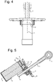
- Figure 4 shows the displacement rod in three different positions when pivoting about the pivot axis 4.
- Figure 5 shows the gear mechanism 19 driving the displacement rod 7 in its length direction.
- a central gear 20 of the motor 2 drives a transmission gear 21 that interacts with the gear 22 that is positioned around the rod 7.
- the inside of the gear 22 is provided with teeth that interact with grooves on the rod so that rotation of the gear 22 moves the rod 7 in its length direction.
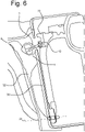
- Figure 6 shows a back rest 30 of a rear seat, hingeable about a lower hinge axis 31.
- the fixation bracket 8 of the drive member 1 is connected to the frame 32 of the vehicle.
- the movable joint 13 of the drive member 1 is attached to an upper flange 33 of the backrest.
- the drive member 1 had been described for the adjustment of the back rest of a rear seat in a motor vehicle, but is not limited thereto.
- the drive member 1 according to the disclosure can be utilized for the adjustment of the relative positons of a wide range of interconnected objects.
Landscapes
- Engineering & Computer Science (AREA)
- Mechanical Engineering (AREA)
- Aviation & Aerospace Engineering (AREA)
- Transportation (AREA)
- General Engineering & Computer Science (AREA)
- Chairs For Special Purposes, Such As Reclining Chairs (AREA)
- Seats For Vehicles (AREA)
Abstract
Description
- The present disclosure relates to a drive member comprising a motor with a longitudinal axis and having at an actuating end a gear mechanism, a support member carrying a displacement rod that is movably mounted on the support member.
- The disclosure also relates to a vehicle comprising a seat with a back rest that is adjustable via such a drive member.
- Motor vehicles having a pivotable rear seat part that is adjustable by a drive member are known. The drive member has a motor comprising a reduction gear mechanism at its output shaft. The gear mechanism drives a threaded spindle shaft via a worm wheel situated in the housing of an output conversion mechanism. The spindle shaft extends in the direction of the seat frame, while the motor drive is oriented with its axis transversely to the spindle shaft, in the plane of the backrest.
- The known drive mechanism is of a relatively heavy construction in order to take up the forces that act on it. Furthermore, the rigid connection of the drive member to the seat and to the vehicle requires small tolerances and is placed under strain during adjustment of the seat when the angle between the drive member and the seat is changed. Also in case of an accident, the direction of the forces transferred from the back rest to the drive mechanism may lead to deformation of the drive mechanism.
- It is an object of the disclosure to provide a drive member that is of reduced weight. It is a further object to provide a drive member and that allows for larger tolerances in the connecting parts and that maintains its functionality during adjustment of the parts. It is again an object to provide a drive member for adjusting a back rest in a vehicle that provides improved safety during a rearward crash.
- A drive member in accordance with the disclosure comprises a motor that is connected by its actuating end to the support member, a gear mechanism that comprises a hinge member which allows pivoting of the displacement rod about a pivot axis that is oriented transversely to the longitudinal axis, the gear mechanism engaging with the displacement rod, the support member being hingedly attached to a fixation bracket by a hinge connection that is hingeable about an axis which is transverse to the longitudinal axis.
- The hinging support of the motor and the displacement rod and the pivoting movement of the displacement rod that is allowed by the gear mechanism, ensure that the rod is properly aligned in the direction of movement and that an efficient push-pull movement is effected. This results in a weight reduction of the drive member, which may be of less than half the weight of the known drive members. Furthermore, the self-alignment of the drive member according to the disclosure allows larger tolerances in the structure, such as a backrest and the frame of a vehicle, that are attached to the drive member. During adjustment of the position of the connected parts, or during a crash in case the drive member is mounted in a vehicle, the drive member according to the disclosure remains aligned with the direction of movement and exerts an efficient push-pull force in the direction of the displacement.
- The displacement rod may extend along the motor in the direction of the longitudinal axis to provide a compact drive member.
- A drive member may have a fixation bracket that comprises a plate-shaped body with a central opening with, at each opposed edge, a flange transverse to the plane of the body, the flanges carrying the support member.
- A proper alignment of the displacement rod is obtained by the drive member pivoting in the opening of the fixation bracket, in which opening the gear mechanism is accommodated.
- The motor may be situated at a first side of the plate-shaped body, the displacement rod extending via the opening to a second side of the body and being provided at that side with a movable joint.
- The motor and the displacement rod extend on respective sides of the fixation bracket, which may be mounted to adjust a backrest of a seat in a vehicle without parts being situated in the plane of the backrest.
- In an embodiment, the displacement rod at the side of the motor comprises a free end that is not provided with attachment means for proper alignment of the rod with the direction of the push and pull forces.
- A vehicle comprising a seat with a back rest than can pivot about a lower pivot axis may comprise a drive member according to the disclosure, the fixation bracket being connected to frame part of the vehicle and the displacement rod being attached to an upper part of the back rest. The seat may be a rear seat.
- The reduced weight of the drive member results in reduced fuel consumption. The placement of the motor and the displacement rod transversely to the plane of the seat ensures that no components interact with the back support surface. Furthermore, the alignment of the displacement rod with the adjusted seat position results in a smooth operation, and during an impact from the rear, the forces are properly transferred from the backrest to the vehicle frame.
- An embodiment of the drive member will, by way of non-limiting example, be described in detail with reference to the accompanying drawings. In the drawings:
-
Fig. 1 shows a perspective view of a drive member according to the disclosure, -
Fig. 2 shows a side view of the drive member offigure 1 , for different positions of the displacement rod, -
Fig. 3 shows a top cross-sectional view of the drive member offigure 1 , -
Fig. 4 shows a top view of the pivoting motion of the displacement rod about the pivot axis, -
Fig. 5 shows a cross-sectional side of the gear mechanism of the drive member offigure 1 , and -
Fig. 6 shows the drive member according to the disclosure connected to a back rest of the rear seat of a motor vehicle. -
Figure 1 shows adrive member 1 according to the present disclosure comprising amotor 2 with alongitudinal axis 3. Themotor 2 is at its actuatingend 5 connected to asupport member 6. A gear mechanism is housed in agearbox 9 and drives adisplacement rod 7 that is slidably mounted in thesupport member 6. Thesupport member 6 is connected to afixation bracket 8 so that it can pivot about theaxis 10 that is oriented transversely to thelongitudinal axis 3. - The
displacement rod 7 comprises on its outer surface a toothed surface that engages with the gear mechanism in thegearbox 9 for displacement of the rod in its length direction. On its attachment end, therod 7 comprises amovable joint 13. At afree end 14 of therod 7, no connection member is provided. - The
fixation bracket 8 comprises a plate-shaped body with acentral opening 11 through which thedisplacement rod 7 extends. Twoside parts 12,12' of thebracket 8 are provided for connection, for instance to a frame part of a vehicle. -
Figure 2 shows a side view of thedrive member 1, in which theflanges 15 of thebracket 8 are visible, that carry themotor 2 in a hinging manner via astub 16 onsupport member 6 that carries thegearbox 9. By hinging in thebrackets 8, the displacement rod can assume the positions indicated by the dotted lines. The displacement rod can pivot about thepivot axis 4. -
Figure 3 shows the connection of thegear box 9 to thesupport member 6 and the pivoting connection of thestubs 16, 16' of the support member6 to theflanges 15,15' of thefixation bracket 8. Thegear box 9 comprisesrounded hinge members displacement rod 7, such that it can pivot aboutpivot axis 4. Thedisplacement rod 7 passes throughopenings support member 6 that leave sufficient space for thedisplacement rod 7 during pivoting about thepivot axis 4. -
Figure 4 shows the displacement rod in three different positions when pivoting about thepivot axis 4. -
Figure 5 shows thegear mechanism 19 driving thedisplacement rod 7 in its length direction. Acentral gear 20 of themotor 2 drives atransmission gear 21 that interacts with thegear 22 that is positioned around therod 7. The inside of thegear 22 is provided with teeth that interact with grooves on the rod so that rotation of thegear 22 moves therod 7 in its length direction. -
Figure 6 shows aback rest 30 of a rear seat, hingeable about alower hinge axis 31. Thefixation bracket 8 of thedrive member 1 is connected to theframe 32 of the vehicle. Themovable joint 13 of thedrive member 1 is attached to anupper flange 33 of the backrest. - In this embodiment, the
drive member 1 had been described for the adjustment of the back rest of a rear seat in a motor vehicle, but is not limited thereto. Thedrive member 1 according to the disclosure can be utilized for the adjustment of the relative positons of a wide range of interconnected objects.
Claims (8)
- Drive member (1) comprising a motor (2) with a longitudinal axis (3) and with at an actuating end (5) a gear mechanism (9), a support member (6) carrying a displacement rod (7) that is movably mounted on the support member (7), the motor (2) being with its actuating end (5) connected to the support member (6), the gear mechanism (9) comprising a hinge member (25,26) allowing pivoting of the displacement rod (7) about a pivot axis (4) that is oriented transversely to the longitudinal axis (3), the gear mechanism (9) engaging with the displacement rod (9), the support member (6) being hingedly attached to a fixation bracket (8) in a hinge connection (15,15',16,16') that is hingeable about an axis (10) which is transverse to the longitudinal axis (3) and to the pivot axis (4).
- Drive member (1) according to claim 1, wherein the displacement rod (7) extends along the motor (2) in the direction of the longitudinal axis (3).
- Drive member (1) according to claim 1 or 2, the gear mechanism (9) comprising a housing through which the displacement rod (7) extends via rounded hinge members (23,25) that are spaced apart in the direction of the longitudinal axis (3), the displacement rod (7) passing through the support member (6) via an opening (23,24) that is larger than the displacement rod (7), such as to provide a pivot space.
- Drive member (1) according to any of the preceding claims, the fixation bracket (8) comprising a plate-shaped body with a central opening (11) with at opposed edges of the opening a flange (15,15') transversely to the plane of the body, the flanges (15,15') carrying the support member (6).
- Drive member (1) according to claim 4, the motor (2) being situated on a first side of the plate shaped body of the fixation bracket (8), the actuating rod (7) extending through the opening (11) to a second side of the plate-shaped body, and being provided at the second side with movable joint (13).
- Drive member (1) according to claim 2, 3, 4 or 5, the displacement rod (7) at the side of the motor (2) comprising a free end (14) that is not provided with attachment means.
- Vehicle comprising a seat with a back rest (30) than can pivot about a lower pivot axis (31) and a drive member (1) according to any of the preceding claims, the fixation bracket (8) being connected to frame part (32) of the vehicle and the displacement rod (7) being attached to an upper part (33) of the back rest (30).
- Vehicle according to claim 7, wherein the seat is a rear seat.
Priority Applications (3)
| Application Number | Priority Date | Filing Date | Title |
|---|---|---|---|
| EP21180118.8A EP4105076A1 (en) | 2021-06-17 | 2021-06-17 | Drive member |
| US17/839,683 US11904738B2 (en) | 2021-06-17 | 2022-06-14 | Drive member |
| CN202210691715.0A CN115556646A (en) | 2021-06-17 | 2022-06-17 | Drive member |
Applications Claiming Priority (1)
| Application Number | Priority Date | Filing Date | Title |
|---|---|---|---|
| EP21180118.8A EP4105076A1 (en) | 2021-06-17 | 2021-06-17 | Drive member |
Publications (1)
| Publication Number | Publication Date |
|---|---|
| EP4105076A1 true EP4105076A1 (en) | 2022-12-21 |
Family
ID=76522814
Family Applications (1)
| Application Number | Title | Priority Date | Filing Date |
|---|---|---|---|
| EP21180118.8A Pending EP4105076A1 (en) | 2021-06-17 | 2021-06-17 | Drive member |
Country Status (3)
| Country | Link |
|---|---|
| US (1) | US11904738B2 (en) |
| EP (1) | EP4105076A1 (en) |
| CN (1) | CN115556646A (en) |
Citations (4)
| Publication number | Priority date | Publication date | Assignee | Title |
|---|---|---|---|---|
| DE102008017017A1 (en) * | 2007-06-19 | 2008-12-24 | C. Rob. Hammerstein Gmbh & Co. Kg | Actuator for a motor vehicle with a transmission housing |
| DE102009022518A1 (en) * | 2009-05-19 | 2010-11-25 | Keiper Gmbh & Co. Kg | Vehicle seat, particularly motor vehicle seat, has backrest which is pivotable around backrest rotation axis relative to vehicle structure |
| DE102010003639A1 (en) * | 2009-04-17 | 2010-12-16 | C. Rob. Hammerstein Gmbh & Co. Kg | Motoric adjusting device of a motor vehicle seat with a gear motor and a control gear |
| US20200040971A1 (en) * | 2018-08-02 | 2020-02-06 | Stabilus Gmbh | Pivotable spindle nut |
Family Cites Families (3)
| Publication number | Priority date | Publication date | Assignee | Title |
|---|---|---|---|---|
| WO2008058529A2 (en) * | 2006-11-17 | 2008-05-22 | Faurecia Autositze Gmbh | Vehicle seat |
| DE102015200816B4 (en) * | 2014-11-14 | 2017-08-03 | Adient Luxembourg Holding S.à.r.l. | Propulsion system for tilt adjustment, vehicle seat, method of operating a propulsion system |
| EP3576977B1 (en) * | 2017-01-31 | 2021-06-09 | Robert Bosch GmbH | Electrically adjustable child seat, in particular for fastening on a motor vehicle seat |
-
2021
- 2021-06-17 EP EP21180118.8A patent/EP4105076A1/en active Pending
-
2022
- 2022-06-14 US US17/839,683 patent/US11904738B2/en active Active
- 2022-06-17 CN CN202210691715.0A patent/CN115556646A/en active Pending
Patent Citations (4)
| Publication number | Priority date | Publication date | Assignee | Title |
|---|---|---|---|---|
| DE102008017017A1 (en) * | 2007-06-19 | 2008-12-24 | C. Rob. Hammerstein Gmbh & Co. Kg | Actuator for a motor vehicle with a transmission housing |
| DE102010003639A1 (en) * | 2009-04-17 | 2010-12-16 | C. Rob. Hammerstein Gmbh & Co. Kg | Motoric adjusting device of a motor vehicle seat with a gear motor and a control gear |
| DE102009022518A1 (en) * | 2009-05-19 | 2010-11-25 | Keiper Gmbh & Co. Kg | Vehicle seat, particularly motor vehicle seat, has backrest which is pivotable around backrest rotation axis relative to vehicle structure |
| US20200040971A1 (en) * | 2018-08-02 | 2020-02-06 | Stabilus Gmbh | Pivotable spindle nut |
Also Published As
| Publication number | Publication date |
|---|---|
| US20220402408A1 (en) | 2022-12-22 |
| US11904738B2 (en) | 2024-02-20 |
| CN115556646A (en) | 2023-01-03 |
Similar Documents
| Publication | Publication Date | Title |
|---|---|---|
| JP3656432B2 (en) | Power seat slide rail structure | |
| EP2019608B1 (en) | Adjustable bolster assembly | |
| CA2179199C (en) | Vehicle power seat adjuster with self-aligning drive nut | |
| US5456439A (en) | Vehicle power seat adjuster with self-aligning lead screw actuator | |
| US5445354A (en) | Track assembly for vehicle power seat adjuster | |
| US4556185A (en) | Seat frame for a vehicle seat | |
| US5172601A (en) | Drive nut and screw for seat adjuster | |
| GB2259001A (en) | Powered seat slide device | |
| EP0371794B1 (en) | Seat arrangement for automotive vehicle with seat position adjusting system | |
| US11760232B2 (en) | Motor vehicle seat | |
| KR20250050393A (en) | Device for adjusting position of vehicle seat | |
| KR20070023836A (en) | Adjustable pedal assembly | |
| US11904738B2 (en) | Drive member | |
| US20180264976A1 (en) | Seat back with power shoulder pivot | |
| US20040249321A1 (en) | Massage system, particularly designed for installation inside the backrest of a vehicle seat | |
| KR910009496A (en) | Power seat lifter for car seat assembly | |
| US12428048B2 (en) | Reach adjustable steering column assembly | |
| EP4541651A1 (en) | Automobile seat and automobile having same | |
| JP2003341393A (en) | Seat vertical adjusting unit | |
| CN115158438B (en) | Steering column capable of adjusting angle and automobile | |
| CN217515037U (en) | Automobile seat leg support, automobile seat and vehicle | |
| CN222291557U (en) | Height-adjustable suspension seat | |
| EP1555179A1 (en) | Adjustable pedal assembly for vehicles | |
| KR20180137987A (en) | Seat Bolster Structure of Vehicle | |
| US12233758B2 (en) | Vehicle seat |
Legal Events
| Date | Code | Title | Description |
|---|---|---|---|
| PUAI | Public reference made under article 153(3) epc to a published international application that has entered the european phase |
Free format text: ORIGINAL CODE: 0009012 |
|
| STAA | Information on the status of an ep patent application or granted ep patent |
Free format text: STATUS: THE APPLICATION HAS BEEN PUBLISHED |
|
| AK | Designated contracting states |
Kind code of ref document: A1 Designated state(s): AL AT BE BG CH CY CZ DE DK EE ES FI FR GB GR HR HU IE IS IT LI LT LU LV MC MK MT NL NO PL PT RO RS SE SI SK SM TR |
|
| STAA | Information on the status of an ep patent application or granted ep patent |
Free format text: STATUS: REQUEST FOR EXAMINATION WAS MADE |
|
| 17P | Request for examination filed |
Effective date: 20230621 |
|
| RBV | Designated contracting states (corrected) |
Designated state(s): AL AT BE BG CH CY CZ DE DK EE ES FI FR GB GR HR HU IE IS IT LI LT LU LV MC MK MT NL NO PL PT RO RS SE SI SK SM TR |
|
| STAA | Information on the status of an ep patent application or granted ep patent |
Free format text: STATUS: EXAMINATION IS IN PROGRESS |
|
| 17Q | First examination report despatched |
Effective date: 20240507 |