EP4104991A1 - Preform, sterilization device, and sterilization method - Google Patents
Preform, sterilization device, and sterilization method Download PDFInfo
- Publication number
- EP4104991A1 EP4104991A1 EP21792721.9A EP21792721A EP4104991A1 EP 4104991 A1 EP4104991 A1 EP 4104991A1 EP 21792721 A EP21792721 A EP 21792721A EP 4104991 A1 EP4104991 A1 EP 4104991A1
- Authority
- EP
- European Patent Office
- Prior art keywords
- section
- axis
- preform
- along
- electron beam
- Prior art date
- Legal status (The legal status is an assumption and is not a legal conclusion. Google has not performed a legal analysis and makes no representation as to the accuracy of the status listed.)
- Withdrawn
Links
Images


Classifications
-
- B—PERFORMING OPERATIONS; TRANSPORTING
- B29—WORKING OF PLASTICS; WORKING OF SUBSTANCES IN A PLASTIC STATE IN GENERAL
- B29C—SHAPING OR JOINING OF PLASTICS; SHAPING OF MATERIAL IN A PLASTIC STATE, NOT OTHERWISE PROVIDED FOR; AFTER-TREATMENT OF THE SHAPED PRODUCTS, e.g. REPAIRING
- B29C49/00—Blow-moulding, i.e. blowing a preform or parison to a desired shape within a mould; Apparatus therefor
- B29C49/42—Component parts, details or accessories; Auxiliary operations
- B29C49/42414—Treatment of preforms, e.g. cleaning or spraying water for improved heat transfer
- B29C49/42416—Purging or cleaning the preforms
- B29C49/42418—Purging or cleaning the preforms for sterilizing
-
- B—PERFORMING OPERATIONS; TRANSPORTING
- B29—WORKING OF PLASTICS; WORKING OF SUBSTANCES IN A PLASTIC STATE IN GENERAL
- B29C—SHAPING OR JOINING OF PLASTICS; SHAPING OF MATERIAL IN A PLASTIC STATE, NOT OTHERWISE PROVIDED FOR; AFTER-TREATMENT OF THE SHAPED PRODUCTS, e.g. REPAIRING
- B29C49/00—Blow-moulding, i.e. blowing a preform or parison to a desired shape within a mould; Apparatus therefor
- B29C49/071—Preforms or parisons characterised by their configuration, e.g. geometry, dimensions or physical properties
-
- A—HUMAN NECESSITIES
- A61—MEDICAL OR VETERINARY SCIENCE; HYGIENE
- A61L—METHODS OR APPARATUS FOR STERILISING MATERIALS OR OBJECTS IN GENERAL; DISINFECTION, STERILISATION OR DEODORISATION OF AIR; CHEMICAL ASPECTS OF BANDAGES, DRESSINGS, ABSORBENT PADS OR SURGICAL ARTICLES; MATERIALS FOR BANDAGES, DRESSINGS, ABSORBENT PADS OR SURGICAL ARTICLES
- A61L2/00—Disinfection or sterilisation of materials or objects, in general; Accessories therefor
- A61L2/02—Disinfection or sterilisation of materials or objects, in general; Accessories therefor using physical processes
- A61L2/08—Radiation
- A61L2/087—Particle radiation, e.g. electron-beam, alpha or beta radiation
-
- A—HUMAN NECESSITIES
- A61—MEDICAL OR VETERINARY SCIENCE; HYGIENE
- A61L—METHODS OR APPARATUS FOR STERILISING MATERIALS OR OBJECTS IN GENERAL; DISINFECTION, STERILISATION OR DEODORISATION OF AIR; CHEMICAL ASPECTS OF BANDAGES, DRESSINGS, ABSORBENT PADS OR SURGICAL ARTICLES; MATERIALS FOR BANDAGES, DRESSINGS, ABSORBENT PADS OR SURGICAL ARTICLES
- A61L2103/00—Materials or objects being the target of disinfection or sterilisation
- A61L2103/23—Containers other than laboratory or medical, e.g. bottles or mail
-
- B—PERFORMING OPERATIONS; TRANSPORTING
- B29—WORKING OF PLASTICS; WORKING OF SUBSTANCES IN A PLASTIC STATE IN GENERAL
- B29C—SHAPING OR JOINING OF PLASTICS; SHAPING OF MATERIAL IN A PLASTIC STATE, NOT OTHERWISE PROVIDED FOR; AFTER-TREATMENT OF THE SHAPED PRODUCTS, e.g. REPAIRING
- B29C2949/00—Indexing scheme relating to blow-moulding
- B29C2949/07—Preforms or parisons characterised by their configuration
- B29C2949/0715—Preforms or parisons characterised by their configuration the preform having one end closed
-
- B—PERFORMING OPERATIONS; TRANSPORTING
- B29—WORKING OF PLASTICS; WORKING OF SUBSTANCES IN A PLASTIC STATE IN GENERAL
- B29C—SHAPING OR JOINING OF PLASTICS; SHAPING OF MATERIAL IN A PLASTIC STATE, NOT OTHERWISE PROVIDED FOR; AFTER-TREATMENT OF THE SHAPED PRODUCTS, e.g. REPAIRING
- B29C2949/00—Indexing scheme relating to blow-moulding
- B29C2949/07—Preforms or parisons characterised by their configuration
- B29C2949/076—Preforms or parisons characterised by their configuration characterised by the shape
- B29C2949/0761—Preforms or parisons characterised by their configuration characterised by the shape characterised by overall the shape
- B29C2949/0762—Conical
-
- B—PERFORMING OPERATIONS; TRANSPORTING
- B29—WORKING OF PLASTICS; WORKING OF SUBSTANCES IN A PLASTIC STATE IN GENERAL
- B29C—SHAPING OR JOINING OF PLASTICS; SHAPING OF MATERIAL IN A PLASTIC STATE, NOT OTHERWISE PROVIDED FOR; AFTER-TREATMENT OF THE SHAPED PRODUCTS, e.g. REPAIRING
- B29C2949/00—Indexing scheme relating to blow-moulding
- B29C2949/07—Preforms or parisons characterised by their configuration
- B29C2949/076—Preforms or parisons characterised by their configuration characterised by the shape
- B29C2949/0768—Preforms or parisons characterised by their configuration characterised by the shape characterised by the shape of specific parts of preform
- B29C2949/077—Preforms or parisons characterised by their configuration characterised by the shape characterised by the shape of specific parts of preform characterised by the neck
- B29C2949/0772—Closure retaining means
- B29C2949/0773—Threads
-
- B—PERFORMING OPERATIONS; TRANSPORTING
- B29—WORKING OF PLASTICS; WORKING OF SUBSTANCES IN A PLASTIC STATE IN GENERAL
- B29C—SHAPING OR JOINING OF PLASTICS; SHAPING OF MATERIAL IN A PLASTIC STATE, NOT OTHERWISE PROVIDED FOR; AFTER-TREATMENT OF THE SHAPED PRODUCTS, e.g. REPAIRING
- B29C2949/00—Indexing scheme relating to blow-moulding
- B29C2949/07—Preforms or parisons characterised by their configuration
- B29C2949/076—Preforms or parisons characterised by their configuration characterised by the shape
- B29C2949/0768—Preforms or parisons characterised by their configuration characterised by the shape characterised by the shape of specific parts of preform
- B29C2949/0778—Preforms or parisons characterised by their configuration characterised by the shape characterised by the shape of specific parts of preform characterised by the flange
-
- B—PERFORMING OPERATIONS; TRANSPORTING
- B29—WORKING OF PLASTICS; WORKING OF SUBSTANCES IN A PLASTIC STATE IN GENERAL
- B29C—SHAPING OR JOINING OF PLASTICS; SHAPING OF MATERIAL IN A PLASTIC STATE, NOT OTHERWISE PROVIDED FOR; AFTER-TREATMENT OF THE SHAPED PRODUCTS, e.g. REPAIRING
- B29C2949/00—Indexing scheme relating to blow-moulding
- B29C2949/07—Preforms or parisons characterised by their configuration
- B29C2949/076—Preforms or parisons characterised by their configuration characterised by the shape
- B29C2949/0768—Preforms or parisons characterised by their configuration characterised by the shape characterised by the shape of specific parts of preform
- B29C2949/078—Preforms or parisons characterised by their configuration characterised by the shape characterised by the shape of specific parts of preform characterised by the bottom
-
- B—PERFORMING OPERATIONS; TRANSPORTING
- B29—WORKING OF PLASTICS; WORKING OF SUBSTANCES IN A PLASTIC STATE IN GENERAL
- B29C—SHAPING OR JOINING OF PLASTICS; SHAPING OF MATERIAL IN A PLASTIC STATE, NOT OTHERWISE PROVIDED FOR; AFTER-TREATMENT OF THE SHAPED PRODUCTS, e.g. REPAIRING
- B29C2949/00—Indexing scheme relating to blow-moulding
- B29C2949/20—Preforms or parisons whereby a specific part is made of only one component, e.g. only one layer
- B29C2949/22—Preforms or parisons whereby a specific part is made of only one component, e.g. only one layer at neck portion
-
- B—PERFORMING OPERATIONS; TRANSPORTING
- B29—WORKING OF PLASTICS; WORKING OF SUBSTANCES IN A PLASTIC STATE IN GENERAL
- B29C—SHAPING OR JOINING OF PLASTICS; SHAPING OF MATERIAL IN A PLASTIC STATE, NOT OTHERWISE PROVIDED FOR; AFTER-TREATMENT OF THE SHAPED PRODUCTS, e.g. REPAIRING
- B29C2949/00—Indexing scheme relating to blow-moulding
- B29C2949/20—Preforms or parisons whereby a specific part is made of only one component, e.g. only one layer
- B29C2949/24—Preforms or parisons whereby a specific part is made of only one component, e.g. only one layer at flange portion
-
- B—PERFORMING OPERATIONS; TRANSPORTING
- B29—WORKING OF PLASTICS; WORKING OF SUBSTANCES IN A PLASTIC STATE IN GENERAL
- B29C—SHAPING OR JOINING OF PLASTICS; SHAPING OF MATERIAL IN A PLASTIC STATE, NOT OTHERWISE PROVIDED FOR; AFTER-TREATMENT OF THE SHAPED PRODUCTS, e.g. REPAIRING
- B29C2949/00—Indexing scheme relating to blow-moulding
- B29C2949/20—Preforms or parisons whereby a specific part is made of only one component, e.g. only one layer
- B29C2949/26—Preforms or parisons whereby a specific part is made of only one component, e.g. only one layer at body portion
-
- B—PERFORMING OPERATIONS; TRANSPORTING
- B29—WORKING OF PLASTICS; WORKING OF SUBSTANCES IN A PLASTIC STATE IN GENERAL
- B29C—SHAPING OR JOINING OF PLASTICS; SHAPING OF MATERIAL IN A PLASTIC STATE, NOT OTHERWISE PROVIDED FOR; AFTER-TREATMENT OF THE SHAPED PRODUCTS, e.g. REPAIRING
- B29C2949/00—Indexing scheme relating to blow-moulding
- B29C2949/20—Preforms or parisons whereby a specific part is made of only one component, e.g. only one layer
- B29C2949/28—Preforms or parisons whereby a specific part is made of only one component, e.g. only one layer at bottom portion
Definitions
- the present disclosure relates to a preform, a sterilization device, and a sterilization method.
- an electron beam sterilization device that irradiates a preform of a container before blow molding with an electron beam to sterilize the preform is known (for example, refer to PTL 1).
- the electron beam sterilization device disclosed in PTL 1 inserts an electron beam irradiation nozzle in a fixed shaft state into the preform by using a raising-lowering device to raise and lower the preform with respect to the electron beam irradiation nozzle.
- the electron beam sterilization device disclosed in PTL 1 performs a sterilization treatment on an inner surface of the preform by irradiating the inner surface of the preform with the electron beam in a state where the electron beam irradiation nozzle is inserted inside the preform.
- the electron beam sterilization device disclosed in the patent literature requires the raising-lowering device for raising and lowering the preform with respect to the electron beam irradiation nozzle. Therefore, manufacturing costs of the electron beam sterilization device increase. In addition, it takes time to perform an operation for raising and lowering the preform with respect to the electron beam irradiation nozzle. Consequently, a time required for performing the sterilization treatment on the preform is lengthened.
- the present disclosure is made in view of the above-described circumstances, and an object of the present disclosure is to provide a preform, a sterilization device, and a sterilization method which can prevent an absorbed radiation dose of an electron beam from being excessively large on a plug section side of the preform while the absorbed radiation dose of the electron beam is sufficiently secured on a base section side of the preform, when a sterilization treatment is performed on the preform by irradiating the preform with an electron beam.
- a preform including a plug section formed in a cylindrical shape along an axis and having one end open, a trunk section formed in a cylindrical shape along the axis and connected to the plug section, and a base section connected to the trunk section and having one end closed along the axis.
- the trunk section has a linear section connected to the plug section and whose first inner diameter in a radial direction orthogonal to the axis is constant at each position along the axis, and an inclined section of which one end along the axis is connected to the linear section and the other end along the axis is connected to the base section, and whose second inner diameter in the radial direction gradually decreases at a constant gradient from the linear section toward the base section along the axis.
- the inclined section is formed so that an inclination angle of an inner peripheral surface with respect to the axis is 12 degrees or larger and 22 degrees or smaller.
- a sterilization method for sterilizing a preform in which the preform includes a plug section formed in a cylindrical shape along an axis and having one end open, a trunk section formed in a cylindrical shape along the axis and connected to the plug section, and a base section connected to the trunk section and having one end closed along the axis, the trunk section has a linear section connected to the plug section and whose first inner diameter in a radial direction orthogonal to the axis is constant at each position along the axis, and an inclined section of which one end along the axis is connected to the linear section and the other end along the axis is connected to the base section, and whose second inner diameter in the radial direction gradually decreases at a constant gradient from the linear section toward the base section along the axis, and the inclined section is formed so that an inclination angle of an inner peripheral surface with respect to the axis is 12 degrees or larger and 22 degrees or smaller.
- the sterilization method includes a transport step of transporting the preform along a transport direction intersecting with the axis, and an irradiation step of irradiating the plug section of the preform with an electron beam in a direction along the axis in a transport path through which the preform is transported by performing the transport step.
- a preform, a sterilization device, and a sterilization method which can prevent an absorbed radiation dose of an electron beam from being excessively large on a plug section side of the preform while the absorbed radiation dose of the electron beam is sufficiently secured on a base section side of the preform, when a sterilization treatment is performed on the preform by irradiating the preform with an electron beam.
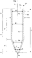
- Fig. 1 is a longitudinal sectional view of a preform 100 according to an embodiment of the present disclosure.
- the preform 100 of the present embodiment is a tubular member having a base section integrally molded from a thermoplastic resin material serving as a primary material, and is a member for manufacturing a plastic bottle through blow molding.
- the thermoplastic resin material used for the preform 100 is polyethylene (PE), polypropylene (PP), polyethylene terephthalate (PET), polyethylene naphthalate (PEN), and polycarbonate (PC).
- the preform 100 of the present embodiment includes a plug section 10, a trunk section 20, and a base section 30.
- the plug section 10, the trunk section 20, and the base section 30 are integrally molded from the thermoplastic resin material.
- the preform 100 has a shape extending along an axis X, in which one end is open on the plug section 10 side and the other end is closed on the base section 30 side.
- An inner diameter D0 of an inner peripheral surface 10a of the plug section 10 is constant at each position along the axis X.
- a length along the axis X from an end portion 100a on the plug section 10 side of the preform 100 to a position where the inner peripheral surface 30a of the base section 30 and the axis X intersect with each other is defined as L1.
- the length L1 is set to 90 mm or longer and 110 mm or shorter.
- the plug section 10 is formed in a cylindrical shape along the axis X, and has a shape in which one end is open in the end portion 100a.
- a male screw 11 spirally extending around the axis X is formed on an outer peripheral surface 10b of the plug section 10. The male screw 11 is used to attach a cap (not illustrated) to a plastic bottle manufactured from the preform 100.
- An annular support ring 12 protruding outward from the outer peripheral surface 10b in a radial direction orthogonal to the axis X is provided in an end portion of the plug section 10 on the base section 30 side.
- the support ring 12 is a member for holding a detachment ring (not illustrated) which is detached from a cap when the plastic bottle is opened.
- the trunk section 20 is formed in a cylindrical shape along the axis X, one end is connected to the plug section 10, and the other end is connected to the base section 30.
- the trunk section 20 has a linear section 21 connected to the plug section 10 and an inclined section 22 connected to the linear section 21 and the base section 30.
- the linear section 21 is a cylindrical member in which one end along the axis X is connected to the plug section 10 and the other end along the axis X is connected to the inclined section 22.
- An inner diameter (first inner diameter) D1 of an inner peripheral surface 21a of the linear section 21 is constant at each position along the axis X.
- the inner diameter D1 of the inner peripheral surface 21a of the linear section 21 is the same as the inner diameter D0 of the inner peripheral surface 10a of the plug section 10.
- the inner diameter D1 is set to 20 mm or larger and 35 mm or smaller.
- the inclined section 22 is a hollow conical member in which one end along the axis X is connected to the linear section 21 and the other end along the axis X is connected to the base section 30.
- the inner diameter (second inner diameter) D2 of the inner peripheral surface 22a of the inclined section 22 gradually decreases with a constant gradient from the linear section 21 toward the base section 30 along the axis X.
- An inner diameter D2 of an inner peripheral surface 22a of the inclined section 22 gradually decreases from the inner diameter D1 of the linear section 21 to the inner diameter D3 of the upper end portion of the base section 30 as the inclined section 22 is closer to the base section 30 from the linear section 21.
- an inclination angle of the inner peripheral surface 22a with respect to the axis X is defined as ⁇ .
- the inclination angle ⁇ is set to satisfy Equation (1) below. 12 ° ⁇ ⁇ ⁇ 22 °
- the inclination angle ⁇ is set to satisfy Equation (2) below. 14 ° ⁇ ⁇ ⁇ 20 °
- the base section 30 has a shape connected to the trunk section 20 and having one end closed along the axis X.
- the base section 30 is a section with which a stretch rod (not illustrated) comes into contact when stretch blow molding is performed.
- Fig. 2 is a view illustrating a state where the preform 100 is irradiated with an electron beam EB from an irradiation unit 200.
- Fig. 3 is a graph illustrating a relationship between a distance from the end portion 100a of the preform 100 and an absorbed radiation dose.
- a sterilization method is adopted as follows. While the preform 100 is transported, an inside of the preform 100 is irradiated with the electron beam. This method is advantageously used in terms of the manufacturing costs, since the method does not require a raising-lowering device of the preform 100, compared to a method of inserting an electron beam irradiation nozzle inside the preform 100.
- the preform 100 is not irradiated with the electron beam inside the preform 100, and is irradiated with the electron beam outside the preform 100. Accordingly, when the absorbed radiation dose of the electron beam is not sufficient in the base section 30 of the preform 100 where a distance from an irradiation source of the electron beam is long, there is a possibility that a sterilization treatment may not be sufficiently performed. Furthermore, when acceleration energy of the electron beam excessively increases to obtain the sufficient absorbed radiation dose of the electron beam in the base section 30 of the preform 100, the absorbed radiation dose of the electron beam excessively increases at a position where a distance from the irradiation source of the electron beam is short. Consequently, there is a possibility that the preform 100 may be deformed or melted.
- the irradiation unit 200 that irradiates the preform 100 with the electron beam EB is used to sterilize the inner peripheral surface 10a, the inner peripheral surface 21a, the inner peripheral surface 22a, and the inner peripheral surface 30a, which are the inner peripheral surfaces of the preform 100.
- the irradiation unit 200 is a device that irradiates the plug section 10 of the preform 100 along the axis X with the electron beam EB.
- the inner diameter D0 of the plug section 10 and the inner diameter D1 of the linear section 21 connected to the plug section 10 are constant at each position along the axis X. Therefore, when the preform 100 is irradiated with the electron beam EB along the axis X, the absorbed radiation dose of the electron beam EB in the plug section 10 and the linear section 21 relatively decreases.
- the inner diameter D2 of the inclined section 22 connected to the linear section 21 gradually decreases toward the base section 30 at a constant gradient from the inner diameter D1 to the inner diameter D3. Accordingly, the absorbed radiation dose of the electron beam EB in the inclined section 22 relatively increases when the preform 100 is irradiated the electron beam EB along the axis X. Therefore, while the absorbed radiation dose of the electron beam EB on the base section 30 side of the preform 100 can be sufficiently secured, the absorbed radiation dose of the electron beam EB on the plug section 10 side of the preform 100 can be prevented from being excessively large.
- the inclined section 22 is formed so that the inclination angle ⁇ of the inner peripheral surface 22a with respect to the axis X is 12 degrees or larger and 22 degrees or smaller.
- the inclination angle ⁇ increases, the absorbed radiation dose per unit area on the base section 30 side increases.
- a region of the inclined section 22 is narrowed, and the absorbed radiation dose of the whole inclined section decreases.
- the region of the inclined section 22 is widened.
- the absorbed radiation dose per unit area on the base section 30 side decreases.
- the inventors have found the followings.
- the inclined section 22 is formed so that the inclination angle is 12 degrees or larger and 22 degrees or smaller, while the absorbed radiation dose of the electron beam EB can be sufficiently secured on the base section 30 side of the preform 100, the absorbed radiation dose of the electron beam EB can be prevented from being excessively large on the plug section 10 side of the preform 100.
- Fig. 3 is a graph illustrating a relationship between a distance from the end portion 100a of the preform 100 and the absorbed radiation dose of the electron beam.
- a horizontal axis illustrated in Fig. 3 indicates a distance in an X-axis direction from the end portion 100a of the inner peripheral surface of the preform 100 when a position of the end portion 100a of the preform 100 is set to 0.
- a maximum value of the distance in the X-axis direction from the end portion 100a is defined as L1.
- a vertical axis illustrated in Fig. 3 indicates a ratio of the absorbed radiation dose of the electron beam EB per unit time and per unit area of the inner peripheral surface of the preform 100 when a predetermined reference value is set to 100%.
- a plot illustrated in Fig. 3 indicates a ratio of the absorbed radiation dose obtained when the inclination angles ⁇ are set to 12°, 17°, 22°, and 45°.
- An example in which the inclination angles ⁇ are set to 12°, 17°, and 22° is an example of the present embodiment which is included in a range of Equation (1) described above.
- an example in which the inclination angle ⁇ is set to 45° is a comparative example of the present embodiment which is not included in the range of Equation (1) described above.
- the absorbed radiation dose greatly decreases after the distance in the X-axis direction from the end portion 100a of the inner peripheral surface of the preform 100 exceeds L1 / 2, and the absorbed radiation dose slightly increases immediately before the distance in the X-axis direction is close to L1.
- the inclination angles ⁇ are 12°, 17°, and 22°
- the absorbed radiation dose increases by switching the linear section 21 to the inclined section 22.
- the absorbed radiation dose decreases as the distance in the X-axis direction is closer to L1 after the absorbed radiation dose increases.
- the absorbed radiation dose at each position from a position where the distance in the X-axis direction is L1 / 2 to the position where the distance is L1 maintains a state where the absorbed radiation dose is larger than that of the comparative example in which the inclination angle ⁇ is set to 45°.
- the length L1 along the axis X from the end portion 100a on the plug section 10 side of the preform 100 to a position where the inner peripheral surface 30a of the base section 30 and the axis X intersect with each other is set to satisfy Equation (3) below.
- the length L1 is set to satisfy Equation (4) below. 1.0 ⁇ D 1 ⁇ L 1 ⁇ 2 . 6 ⁇ D 1
- Fig. 4 is a view illustrating the sterilization device 400 according to the present embodiment.
- the sterilization device 400 includes the irradiation unit 200 and the transport unit 300.
- An example illustrated in Fig. 4 indicates a state where the transport unit 300 transports three preforms 100.
- the transport unit 300 can transport any desired number of the preforms 100, for example, three or more preforms 100.
- the irradiation unit 200 is a device that irradiates the plug section 10 of the preform 100 with the electron beam EB in the direction along the axis X.
- the irradiation unit 200 is disposed in the transport path 320 through which the transport unit 300 transports the preform 100.
- the irradiation unit 200 irradiates the preform 100 with the electron beam EB so that the electron beam EB reaches the base section 30 from the outside of the preform 100 via the plug section 10.
- a length L2 along the axis X from a position where the irradiation unit 200 of the present embodiment irradiates the preform 100 with the electron beam EB to the plug section 10 of the preform 100 is set to approximately 20 mm, for example.
- the acceleration energy of the electron beam EB used for irradiation from the irradiation unit 200 is set to 120 eV or higher and 180 eV or lower.
- the transport unit 300 is a device that transports a plurality of the preforms 100 along a transport direction TD orthogonal to (intersecting with) the axis X.
- the transport unit 300 includes a plurality of holding portions 310 for holding the plurality of preforms 100.
- the transport unit 300 transports the preform 100 to pass below the irradiation unit 200 disposed in the transport path 320 by moving the holding portion 310 along the transport direction TD at a constant speed.
- a transport speed at which the transport unit 300 transports the preform 100 along the transport direction TD is set to 300 mm/sec or higher and 500 mm/sec or lower.
- the sterilization device 400 of the present embodiment performs a sterilization treatment on the preform 100 as follows.
- the preform 100 is installed to be held by the holding portion 310 of the transport unit 300.
- the preform 100 is transported along the transport direction TD by the transport unit 300 (transport step).
- the preform 100 is irradiated with the electron beam EB from the irradiation unit 200, and the electron beam is caused to reach the inner peripheral surface of the preform 100 passing below the irradiation unit 200 (irradiation step).
- the preform including the plug section (10) formed in a cylindrical shape along the axis (X) and having one end open, the trunk section (20) formed in a cylindrical shape along the axis (X) and connected to the plug section (10), and the base section (30) connected to the trunk section and having one end closed along the axis.
- the trunk section has the linear section (21) connected to the plug section and whose first inner diameter (D1) in the radial direction orthogonal to the axis is constant at each position along the axis, and the inclined section (22) of which one end along the axis is connected to the linear section and the other end along the axis is connected to the base section, and whose second inner diameter (D2) in the radial direction gradually decreases at a constant gradient from the linear section toward the base section along the axis.
- the inclined section is formed so that the inclination angle of the inner peripheral surface with respect to the axis is 12 degrees or larger and 22 degrees or smaller.
- the trunk section connected to the plug section has the linear section connected to the plug section and whose first inner diameter in the radial direction is constant at each position along the axis, and the inclined section connected to the linear section and whose second inner diameter in the radial direction gradually decreases at the constant gradient from the linear section toward the base section.
- the first inner diameter of the linear section connected to the plug section is constant at each position along the axis. Therefore, the absorbed radiation dose of the linear section relatively decreases when the preform is irradiated with the electron beam along the axis.
- the second inner diameter of the inclined section connected to the linear section gradually decreases at the constant gradient toward the base section. Therefore, the absorbed radiation dose of the inclined section relatively increases when the preform is irradiated with the electron beam along the axis. Therefore, while the absorbed radiation dose of the electron beam on the base section side of the preform can be sufficiently secured, the absorbed radiation dose of the electron beam on the plug section side of the preform can be prevented from being excessively large.
- the inclined section is formed so that the inclination angle of the inner peripheral surface with respect to the axis is 12 degrees or larger and 22 degrees or smaller.
- the absorbed radiation dose per unit area on the base section side increases.
- the region of the inclined section is narrowed, and the absorbed radiation dose of the whole inclined section decreases.
- the region of the inclined section is widened.
- the absorbed radiation dose per unit area on the base section side decreases.
- the absorbed radiation dose of the electron beam can be sufficiently secured on the base section side of the preform, the absorbed radiation dose of the electron beam can be prevented from being excessively large on the plug section side of the preform.
- the length from the end portion of the plug section (10) along the axis (X) to the base section (30) may be equal to or shorter than three times the first inner diameter (D1).
- the distance from the irradiation source of the electron beam to the base section is sufficiently short with respect to the first inner diameter of the linear section. Therefore, the distance from the irradiation source of the electron beam to the base section is lengthened with respect to the first inner diameter, and the absorbed radiation dose of the electron beam on the base section side can be prevented from being excessively reduced.
- the sterilization device (300) in each of the above-described embodiments can be understood as follows.
- the sterilization device including the transport unit (300) that transports the above-described preform along the transport direction (TD) intersecting with the axis (X), and the irradiation unit (200) disposed in the transport path (320) through which the transport unit (300) transports the preform, and irradiating the plug section of the preform with the electron beam in the direction along the axis.
- the sterilization device of the present disclosure while the absorbed radiation dose of the electron beam can be sufficiently secured on the base section side of the preform, the absorbed radiation dose of the electron beam can be prevented from being excessively large on the plug section side of the preform. In addition, it is not necessary to insert the irradiation source of the electron beam into the preform. Therefore, manufacturing costs of the sterilization device can be reduced.
- the sterilization method for sterilizing the preform in which the preform includes the plug section formed in a cylindrical shape along the axis and having one end open, the trunk section formed in a cylindrical shape along the axis and connected to the plug section, and the base section connected to the trunk section and having one end closed along the axis.
- the trunk section has the linear section connected to the plug section and whose first inner diameter in the radial direction orthogonal to the axis is constant at each position along the axis, and the inclined section of which one end along the axis is connected to the linear section and the other end along the axis is connected to the base section, and whose second inner diameter in the radial direction gradually decreases at a constant gradient from the linear section toward the base section along the axis.
- the inclined section is formed so that an inclination angle of an inner peripheral surface with respect to the axis is 12 degrees or larger and 22 degrees or smaller.
- the sterilization method includes the transport step of transporting the preform along a transport direction intersecting with the axis, and the irradiation step of irradiating the plug section of the preform with an electron beam in a direction along the axis in a transport path through which the preform is transported by performing the transport step.
- the sterilization method of the present disclosure while the absorbed radiation dose of the electron beam can be sufficiently secured on the base section side of the preform, the absorbed radiation dose of the electron beam can be prevented from being excessively large on the plug section side of the preform. In addition, it is not necessary to insert the irradiation source of the electron beam into the preform. Therefore, a sterilization treatment can be performed on the preform by using a relatively easy method.
Landscapes
- Engineering & Computer Science (AREA)
- Manufacturing & Machinery (AREA)
- Mechanical Engineering (AREA)
- Physics & Mathematics (AREA)
- Health & Medical Sciences (AREA)
- Thermal Sciences (AREA)
- Life Sciences & Earth Sciences (AREA)
- Epidemiology (AREA)
- Geometry (AREA)
- Animal Behavior & Ethology (AREA)
- General Health & Medical Sciences (AREA)
- Public Health (AREA)
- Veterinary Medicine (AREA)
- Apparatus For Disinfection Or Sterilisation (AREA)
- Blow-Moulding Or Thermoforming Of Plastics Or The Like (AREA)
- Processing And Handling Of Plastics And Other Materials For Molding In General (AREA)
Abstract
Description
- The present disclosure relates to a preform, a sterilization device, and a sterilization method.
- In the related art, an electron beam sterilization device that irradiates a preform of a container before blow molding with an electron beam to sterilize the preform is known (for example, refer to PTL 1). The electron beam sterilization device disclosed in PTL 1 inserts an electron beam irradiation nozzle in a fixed shaft state into the preform by using a raising-lowering device to raise and lower the preform with respect to the electron beam irradiation nozzle. The electron beam sterilization device disclosed in PTL 1 performs a sterilization treatment on an inner surface of the preform by irradiating the inner surface of the preform with the electron beam in a state where the electron beam irradiation nozzle is inserted inside the preform.
- [PTL 1]
Japanese Patent No. 6091373 - However, the electron beam sterilization device disclosed in the patent literature requires the raising-lowering device for raising and lowering the preform with respect to the electron beam irradiation nozzle. Therefore, manufacturing costs of the electron beam sterilization device increase. In addition, it takes time to perform an operation for raising and lowering the preform with respect to the electron beam irradiation nozzle. Consequently, a time required for performing the sterilization treatment on the preform is lengthened.
- In order to avoid an increase in the manufacturing costs of the electron beam sterilization device or the time required for performing the sterilization treatment, it is conceivable to apply a method for irradiating an inside of the preform with the electron beam while transporting the preform. However, when an absorbed radiation dose of the electron beam is not sufficient in a base section of the preform where a distance from an irradiation source of the electron beam is long, there is a possibility that the sterilization treatment may not be sufficiently performed. On the other hand, when acceleration energy of the electron beam is excessively high to obtain the sufficient absorbed radiation dose of the electron beam in the base section of the preform, the absorbed radiation dose of the electron beam is excessively large at a position where the distance from the irradiation source of the electron beam is short. Therefore, there is a possibility that the preform may be deformed or melted.
- The present disclosure is made in view of the above-described circumstances, and an object of the present disclosure is to provide a preform, a sterilization device, and a sterilization method which can prevent an absorbed radiation dose of an electron beam from being excessively large on a plug section side of the preform while the absorbed radiation dose of the electron beam is sufficiently secured on a base section side of the preform, when a sterilization treatment is performed on the preform by irradiating the preform with an electron beam.
- According to an aspect of the present disclosure, there is provided a preform including a plug section formed in a cylindrical shape along an axis and having one end open, a trunk section formed in a cylindrical shape along the axis and connected to the plug section, and a base section connected to the trunk section and having one end closed along the axis. The trunk section has a linear section connected to the plug section and whose first inner diameter in a radial direction orthogonal to the axis is constant at each position along the axis, and an inclined section of which one end along the axis is connected to the linear section and the other end along the axis is connected to the base section, and whose second inner diameter in the radial direction gradually decreases at a constant gradient from the linear section toward the base section along the axis. The inclined section is formed so that an inclination angle of an inner peripheral surface with respect to the axis is 12 degrees or larger and 22 degrees or smaller.
- According to another aspect of the present disclosure, there is provided a sterilization method for sterilizing a preform in which the preform includes a plug section formed in a cylindrical shape along an axis and having one end open, a trunk section formed in a cylindrical shape along the axis and connected to the plug section, and a base section connected to the trunk section and having one end closed along the axis, the trunk section has a linear section connected to the plug section and whose first inner diameter in a radial direction orthogonal to the axis is constant at each position along the axis, and an inclined section of which one end along the axis is connected to the linear section and the other end along the axis is connected to the base section, and whose second inner diameter in the radial direction gradually decreases at a constant gradient from the linear section toward the base section along the axis, and the inclined section is formed so that an inclination angle of an inner peripheral surface with respect to the axis is 12 degrees or larger and 22 degrees or smaller. The sterilization method includes a transport step of transporting the preform along a transport direction intersecting with the axis, and an irradiation step of irradiating the plug section of the preform with an electron beam in a direction along the axis in a transport path through which the preform is transported by performing the transport step.
- According to the present disclosure, it is possible to provide a preform, a sterilization device, and a sterilization method which can prevent an absorbed radiation dose of an electron beam from being excessively large on a plug section side of the preform while the absorbed radiation dose of the electron beam is sufficiently secured on a base section side of the preform, when a sterilization treatment is performed on the preform by irradiating the preform with an electron beam.
-
-
Fig. 1 is a longitudinal sectional view of a preform according to an embodiment of the present disclosure. -
Fig. 2 is a view illustrating a state where the preform is irradiated with an electron beam from an irradiation unit. -
Fig. 3 is a graph illustrating a relationship between a distance from an end portion of the preform and an absorbed radiation dose of the electron beam. -
Fig. 4 is a view illustrating a sterilization device according to an embodiment of the present disclosure. Description of Embodiments - Hereinafter, an embodiment of a preform, a sterilization device, and a sterilization method according to the present disclosure will be described with reference to the drawings.
Fig. 1 is a longitudinal sectional view of apreform 100 according to an embodiment of the present disclosure. - The
preform 100 of the present embodiment is a tubular member having a base section integrally molded from a thermoplastic resin material serving as a primary material, and is a member for manufacturing a plastic bottle through blow molding. For example, the thermoplastic resin material used for thepreform 100 is polyethylene (PE), polypropylene (PP), polyethylene terephthalate (PET), polyethylene naphthalate (PEN), and polycarbonate (PC). - As illustrated in
Fig. 1 , thepreform 100 of the present embodiment includes aplug section 10, atrunk section 20, and abase section 30. Theplug section 10, thetrunk section 20, and thebase section 30 are integrally molded from the thermoplastic resin material. Thepreform 100 has a shape extending along an axis X, in which one end is open on theplug section 10 side and the other end is closed on thebase section 30 side. - An inner diameter D0 of an inner
peripheral surface 10a of theplug section 10 is constant at each position along the axis X. A length along the axis X from anend portion 100a on theplug section 10 side of thepreform 100 to a position where the innerperipheral surface 30a of thebase section 30 and the axis X intersect with each other is defined as L1. For example, in a case of thepreform 100 used for a plastic bottle having a volume of 600 mL or smaller, the length L1 is set to 90 mm or longer and 110 mm or shorter. - The
plug section 10 is formed in a cylindrical shape along the axis X, and has a shape in which one end is open in theend portion 100a. Amale screw 11 spirally extending around the axis X is formed on an outerperipheral surface 10b of theplug section 10. Themale screw 11 is used to attach a cap (not illustrated) to a plastic bottle manufactured from thepreform 100. - An
annular support ring 12 protruding outward from the outerperipheral surface 10b in a radial direction orthogonal to the axis X is provided in an end portion of theplug section 10 on thebase section 30 side. Thesupport ring 12 is a member for holding a detachment ring (not illustrated) which is detached from a cap when the plastic bottle is opened. - The
trunk section 20 is formed in a cylindrical shape along the axis X, one end is connected to theplug section 10, and the other end is connected to thebase section 30. Thetrunk section 20 has alinear section 21 connected to theplug section 10 and aninclined section 22 connected to thelinear section 21 and thebase section 30. - The
linear section 21 is a cylindrical member in which one end along the axis X is connected to theplug section 10 and the other end along the axis X is connected to theinclined section 22. An inner diameter (first inner diameter) D1 of an innerperipheral surface 21a of thelinear section 21 is constant at each position along the axis X. The inner diameter D1 of the innerperipheral surface 21a of thelinear section 21 is the same as the inner diameter D0 of the innerperipheral surface 10a of theplug section 10. For example, the inner diameter D1 is set to 20 mm or larger and 35 mm or smaller. - The
inclined section 22 is a hollow conical member in which one end along the axis X is connected to thelinear section 21 and the other end along the axis X is connected to thebase section 30. The inner diameter (second inner diameter) D2 of the innerperipheral surface 22a of theinclined section 22 gradually decreases with a constant gradient from thelinear section 21 toward thebase section 30 along the axis X. An inner diameter D2 of an innerperipheral surface 22a of theinclined section 22 gradually decreases from the inner diameter D1 of thelinear section 21 to the inner diameter D3 of the upper end portion of thebase section 30 as theinclined section 22 is closer to thebase section 30 from thelinear section 21. - As illustrated in
Fig. 1 , in theinclined section 22, an inclination angle of the innerperipheral surface 22a with respect to the axis X is defined as θ. In the present embodiment, the inclination angle θ is set to satisfy Equation (1) below.
- In addition, it is more desirable that the inclination angle θ is set to satisfy Equation (2) below.

- The
base section 30 has a shape connected to thetrunk section 20 and having one end closed along the axis X. Thebase section 30 is a section with which a stretch rod (not illustrated) comes into contact when stretch blow molding is performed. - Next, referring to
Figs. 2 and3 , a reason that thepreform 100 of the present embodiment adopts a shape having theinclined section 22 will be described.Fig. 2 is a view illustrating a state where thepreform 100 is irradiated with an electron beam EB from anirradiation unit 200.Fig. 3 is a graph illustrating a relationship between a distance from theend portion 100a of thepreform 100 and an absorbed radiation dose. - As will be described later, in the present embodiment, in order to avoid an increase in manufacturing costs of a
sterilization device 400 and a time required for a sterilization treatment, a sterilization method is adopted as follows. While thepreform 100 is transported, an inside of thepreform 100 is irradiated with the electron beam. This method is advantageously used in terms of the manufacturing costs, since the method does not require a raising-lowering device of thepreform 100, compared to a method of inserting an electron beam irradiation nozzle inside thepreform 100. - On the other hand, the
preform 100 is not irradiated with the electron beam inside thepreform 100, and is irradiated with the electron beam outside thepreform 100. Accordingly, when the absorbed radiation dose of the electron beam is not sufficient in thebase section 30 of thepreform 100 where a distance from an irradiation source of the electron beam is long, there is a possibility that a sterilization treatment may not be sufficiently performed. Furthermore, when acceleration energy of the electron beam excessively increases to obtain the sufficient absorbed radiation dose of the electron beam in thebase section 30 of thepreform 100, the absorbed radiation dose of the electron beam excessively increases at a position where a distance from the irradiation source of the electron beam is short. Consequently, there is a possibility that thepreform 100 may be deformed or melted. - As illustrated in
Fig. 2 , in the present embodiment, theirradiation unit 200 that irradiates thepreform 100 with the electron beam EB is used to sterilize the innerperipheral surface 10a, the innerperipheral surface 21a, the innerperipheral surface 22a, and the innerperipheral surface 30a, which are the inner peripheral surfaces of thepreform 100. Theirradiation unit 200 is a device that irradiates theplug section 10 of thepreform 100 along the axis X with the electron beam EB. - As illustrated in
Fig. 2 , in thepreform 100 of the present embodiment, the inner diameter D0 of theplug section 10 and the inner diameter D1 of thelinear section 21 connected to theplug section 10 are constant at each position along the axis X. Therefore, when thepreform 100 is irradiated with the electron beam EB along the axis X, the absorbed radiation dose of the electron beam EB in theplug section 10 and thelinear section 21 relatively decreases. - On the other hand, in the
preform 100 of the present embodiment, the inner diameter D2 of theinclined section 22 connected to thelinear section 21 gradually decreases toward thebase section 30 at a constant gradient from the inner diameter D1 to the inner diameter D3. Accordingly, the absorbed radiation dose of the electron beam EB in theinclined section 22 relatively increases when thepreform 100 is irradiated the electron beam EB along the axis X. Therefore, while the absorbed radiation dose of the electron beam EB on thebase section 30 side of thepreform 100 can be sufficiently secured, the absorbed radiation dose of the electron beam EB on theplug section 10 side of thepreform 100 can be prevented from being excessively large. - In addition, according to the
preform 100 of the present embodiment, theinclined section 22 is formed so that the inclination angle θ of the innerperipheral surface 22a with respect to the axis X is 12 degrees or larger and 22 degrees or smaller. As the inclination angle θ increases, the absorbed radiation dose per unit area on thebase section 30 side increases. However, a region of theinclined section 22 is narrowed, and the absorbed radiation dose of the whole inclined section decreases. In addition, as the inclination angle θ decreases, the region of theinclined section 22 is widened. However, the absorbed radiation dose per unit area on thebase section 30 side decreases. - As a result of studying the inclination angle of the inclined section while adjusting the inclination angle of the inclined section, the inventors have found the followings. When the
inclined section 22 is formed so that the inclination angle is 12 degrees or larger and 22 degrees or smaller, while the absorbed radiation dose of the electron beam EB can be sufficiently secured on thebase section 30 side of thepreform 100, the absorbed radiation dose of the electron beam EB can be prevented from being excessively large on theplug section 10 side of thepreform 100. -
Fig. 3 is a graph illustrating a relationship between a distance from theend portion 100a of thepreform 100 and the absorbed radiation dose of the electron beam. A horizontal axis illustrated inFig. 3 indicates a distance in an X-axis direction from theend portion 100a of the inner peripheral surface of thepreform 100 when a position of theend portion 100a of thepreform 100 is set to 0. A maximum value of the distance in the X-axis direction from theend portion 100a is defined as L1. - A vertical axis illustrated in
Fig. 3 indicates a ratio of the absorbed radiation dose of the electron beam EB per unit time and per unit area of the inner peripheral surface of thepreform 100 when a predetermined reference value is set to 100%. A plot illustrated inFig. 3 indicates a ratio of the absorbed radiation dose obtained when the inclination angles θ are set to 12°, 17°, 22°, and 45°. An example in which the inclination angles θ are set to 12°, 17°, and 22° is an example of the present embodiment which is included in a range of Equation (1) described above. On the other hand, an example in which the inclination angle θ is set to 45° is a comparative example of the present embodiment which is not included in the range of Equation (1) described above. - As illustrated in
Fig. 3 , in the example where the inclination angle θ is set to 45°, the absorbed radiation dose greatly decreases after the distance in the X-axis direction from theend portion 100a of the inner peripheral surface of thepreform 100 exceeds L1 / 2, and the absorbed radiation dose slightly increases immediately before the distance in the X-axis direction is close to L1. On the other hand, in the example in which the inclination angles θ are 12°, 17°, and 22°, after the distance in the X-axis direction from theend portion 100a of the inner peripheral surface of thepreform 100 exceeds L1 / 2, the absorbed radiation dose increases by switching thelinear section 21 to theinclined section 22. - In the example where the inclination angles θ are set to 12°, 17°, and 22°, the absorbed radiation dose decreases as the distance in the X-axis direction is closer to L1 after the absorbed radiation dose increases. However, the absorbed radiation dose at each position from a position where the distance in the X-axis direction is L1 / 2 to the position where the distance is L1 maintains a state where the absorbed radiation dose is larger than that of the comparative example in which the inclination angle θ is set to 45°. Based on the above-described result, the inventors set the inclination angle θ within the range of Equation (1) described above.
- In the present embodiment, the length L1 along the axis X from the
end portion 100a on theplug section 10 side of thepreform 100 to a position where the innerperipheral surface 30a of thebase section 30 and the axis X intersect with each other is set to satisfy Equation (3) below.
- In addition, it is more desirable that the length L1 is set to satisfy Equation (4) below.

- Next, the
sterilization device 400 of the present embodiment will be described with reference toFig. 4. Fig. 4 is a view illustrating thesterilization device 400 according to the present embodiment. As illustrated inFig. 4 , thesterilization device 400 includes theirradiation unit 200 and thetransport unit 300. An example illustrated inFig. 4 indicates a state where thetransport unit 300 transports threepreforms 100. However, thetransport unit 300 can transport any desired number of thepreforms 100, for example, three ormore preforms 100. - The
irradiation unit 200 is a device that irradiates theplug section 10 of thepreform 100 with the electron beam EB in the direction along the axis X. Theirradiation unit 200 is disposed in thetransport path 320 through which thetransport unit 300 transports thepreform 100. - The
irradiation unit 200 irradiates thepreform 100 with the electron beam EB so that the electron beam EB reaches thebase section 30 from the outside of thepreform 100 via theplug section 10. A length L2 along the axis X from a position where theirradiation unit 200 of the present embodiment irradiates thepreform 100 with the electron beam EB to theplug section 10 of thepreform 100 is set to approximately 20 mm, for example. - For example, the acceleration energy of the electron beam EB used for irradiation from the
irradiation unit 200 is set to 120 eV or higher and 180 eV or lower. For example, it is desirable to set the acceleration energy so that a minimum value of the absorbed radiation dose of the electron beam EB in the inner peripheral surface of thepreform 100 is approximately 15 kGy. - The
transport unit 300 is a device that transports a plurality of thepreforms 100 along a transport direction TD orthogonal to (intersecting with) the axis X. Thetransport unit 300 includes a plurality of holdingportions 310 for holding the plurality ofpreforms 100. Thetransport unit 300 transports thepreform 100 to pass below theirradiation unit 200 disposed in thetransport path 320 by moving the holdingportion 310 along the transport direction TD at a constant speed. For example, a transport speed at which thetransport unit 300 transports thepreform 100 along the transport direction TD is set to 300 mm/sec or higher and 500 mm/sec or lower. - The
sterilization device 400 of the present embodiment performs a sterilization treatment on thepreform 100 as follows. - First, the
preform 100 is installed to be held by the holdingportion 310 of thetransport unit 300. - Second, in a state where the
preform 100 is held by the holdingportion 310, thepreform 100 is transported along the transport direction TD by the transport unit 300 (transport step). - Third, in a state where the
preform 100 is transported along the transport direction TD by thetransport unit 300, thepreform 100 is irradiated with the electron beam EB from theirradiation unit 200, and the electron beam is caused to reach the inner peripheral surface of thepreform 100 passing below the irradiation unit 200 (irradiation step). - For example, the preform (100) described in each of the above-described embodiments can be understood as follows.
- According to the present disclosure, there is provided the preform including the plug section (10) formed in a cylindrical shape along the axis (X) and having one end open, the trunk section (20) formed in a cylindrical shape along the axis (X) and connected to the plug section (10), and the base section (30) connected to the trunk section and having one end closed along the axis. The trunk section has the linear section (21) connected to the plug section and whose first inner diameter (D1) in the radial direction orthogonal to the axis is constant at each position along the axis, and the inclined section (22) of which one end along the axis is connected to the linear section and the other end along the axis is connected to the base section, and whose second inner diameter (D2) in the radial direction gradually decreases at a constant gradient from the linear section toward the base section along the axis. The inclined section is formed so that the inclination angle of the inner peripheral surface with respect to the axis is 12 degrees or larger and 22 degrees or smaller.
- According to the preform of the present disclosure, the trunk section connected to the plug section has the linear section connected to the plug section and whose first inner diameter in the radial direction is constant at each position along the axis, and the inclined section connected to the linear section and whose second inner diameter in the radial direction gradually decreases at the constant gradient from the linear section toward the base section.
- The first inner diameter of the linear section connected to the plug section is constant at each position along the axis. Therefore, the absorbed radiation dose of the linear section relatively decreases when the preform is irradiated with the electron beam along the axis. On the other hand, the second inner diameter of the inclined section connected to the linear section gradually decreases at the constant gradient toward the base section. Therefore, the absorbed radiation dose of the inclined section relatively increases when the preform is irradiated with the electron beam along the axis. Therefore, while the absorbed radiation dose of the electron beam on the base section side of the preform can be sufficiently secured, the absorbed radiation dose of the electron beam on the plug section side of the preform can be prevented from being excessively large.
- In addition, according to the preform of the present disclosure, the inclined section is formed so that the inclination angle of the inner peripheral surface with respect to the axis is 12 degrees or larger and 22 degrees or smaller. As the inclination angle increases, the absorbed radiation dose per unit area on the base section side increases. However, the region of the inclined section is narrowed, and the absorbed radiation dose of the whole inclined section decreases. In addition, as the inclination angle decreases, the region of the inclined section is widened. However, the absorbed radiation dose per unit area on the base section side decreases. As a result of studying the inclination angle of the inclined section while adjusting the inclination angle of the inclined section, the inventors have found the followings. When the inclined section is formed so that the inclination angle is 12 degrees or larger and 22 degrees or smaller, while the absorbed radiation dose of the electron beam can be sufficiently secured on the base section side of the preform, the absorbed radiation dose of the electron beam can be prevented from being excessively large on the plug section side of the preform.
- In the preform according to the present disclosure, the length from the end portion of the plug section (10) along the axis (X) to the base section (30) may be equal to or shorter than three times the first inner diameter (D1).
- Since the length from the end portion of the plug section to the base section is equal to or shorter than three times the first inner diameter of the linear section, the distance from the irradiation source of the electron beam to the base section is sufficiently short with respect to the first inner diameter of the linear section. Therefore, the distance from the irradiation source of the electron beam to the base section is lengthened with respect to the first inner diameter, and the absorbed radiation dose of the electron beam on the base section side can be prevented from being excessively reduced.
- For example, the sterilization device (300) in each of the above-described embodiments can be understood as follows.
- According to the present disclosure, there is provided the sterilization device including the transport unit (300) that transports the above-described preform along the transport direction (TD) intersecting with the axis (X), and the irradiation unit (200) disposed in the transport path (320) through which the transport unit (300) transports the preform, and irradiating the plug section of the preform with the electron beam in the direction along the axis.
- According to the sterilization device of the present disclosure, while the absorbed radiation dose of the electron beam can be sufficiently secured on the base section side of the preform, the absorbed radiation dose of the electron beam can be prevented from being excessively large on the plug section side of the preform. In addition, it is not necessary to insert the irradiation source of the electron beam into the preform. Therefore, manufacturing costs of the sterilization device can be reduced.
- For example, the sterilization method in each of the above-described embodiments can be understood as follows.
- According to the present disclosure, there is provided the sterilization method for sterilizing the preform, in which the preform includes the plug section formed in a cylindrical shape along the axis and having one end open, the trunk section formed in a cylindrical shape along the axis and connected to the plug section, and the base section connected to the trunk section and having one end closed along the axis. The trunk section has the linear section connected to the plug section and whose first inner diameter in the radial direction orthogonal to the axis is constant at each position along the axis, and the inclined section of which one end along the axis is connected to the linear section and the other end along the axis is connected to the base section, and whose second inner diameter in the radial direction gradually decreases at a constant gradient from the linear section toward the base section along the axis. The inclined section is formed so that an inclination angle of an inner peripheral surface with respect to the axis is 12 degrees or larger and 22 degrees or smaller. The sterilization method includes the transport step of transporting the preform along a transport direction intersecting with the axis, and the irradiation step of irradiating the plug section of the preform with an electron beam in a direction along the axis in a transport path through which the preform is transported by performing the transport step.
- According to the sterilization method of the present disclosure, while the absorbed radiation dose of the electron beam can be sufficiently secured on the base section side of the preform, the absorbed radiation dose of the electron beam can be prevented from being excessively large on the plug section side of the preform. In addition, it is not necessary to insert the irradiation source of the electron beam into the preform. Therefore, a sterilization treatment can be performed on the preform by using a relatively easy method.
-
- 10:
- Plug section
- 20:
- Trunk section
- 21:
- Linear section
- 21a:
- Inner peripheral surface
- 22:
- Inclined section
- 22a:
- Inner peripheral surface
- 30:
- Base section
- 30a:
- Inner peripheral surface
- 100:
- Preform
- 100a:
- End portion
- 200:
- Irradiation unit
- 300:
- Transport unit
- 320:
- Transport path
- 400:
- Sterilization device
- EB:
- Electron beam
- TD:
- Transport direction
- X:
- Axis
- θ:
- Inclination angle
Claims (4)
- A preform comprising:a plug section formed in a cylindrical shape along an axis and having one end open;a trunk section formed in a cylindrical shape along the axis and connected to the plug section; anda base section connected to the trunk section and having one end closed along the axis,wherein the trunk section hasa linear section connected to the plug section and whose first inner diameter in a radial direction orthogonal to the axis is constant at each position along the axis, andan inclined section of which one end along the axis is connected to the linear section and the other end along the axis is connected to the base section, and whose second inner diameter in the radial direction gradually decreases at a constant gradient from the linear section toward the base section along the axis, andthe inclined section is formed so that an inclination angle of an inner peripheral surface with respect to the axis is 12 degrees or larger and 22 degrees or smaller.
- The preform according to Claim 1,
wherein a length from an end portion of the plug section to the base section along the axis is equal to or shorter than 3 times the first inner diameter. - A sterilization device comprising:a transport unit that transports the preform according to Claim 1 or 2 along a transport direction intersecting with the axis; andan irradiation unit disposed in a transport path through which the transport unit transports the preform, and irradiating the plug section of the preform with an electron beam in a direction along the axis.
- A sterilization method for sterilizing a preform, in which the preform includesa plug section formed in a cylindrical shape along an axis and having one end open,a trunk section formed in a cylindrical shape along the axis and connected to the plug section, anda base section connected to the trunk section and having one end closed along the axis,the trunk section hasa linear section connected to the plug section and whose first inner diameter in a radial direction orthogonal to the axis is constant at each position along the axis, andan inclined section of which one end along the axis is connected to the plug section and the other end along the axis is connected to the base section, and whose second inner diameter in the radial direction gradually decreases at a constant gradient from the plug section toward the base section along the axis, andthe inclined section is formed so that an inclination angle of an inner peripheral surface with respect to the axis is 12 degrees or larger and 22 degrees or smaller,the sterilization method comprising:a transport step of transporting the preform along a transport direction intersecting with the axis; andan irradiation step of irradiating the plug section of the preform with an electron beam in a direction along the axis in a transport path through which the preform is transported by performing the transport step.
Applications Claiming Priority (2)
| Application Number | Priority Date | Filing Date | Title |
|---|---|---|---|
| JP2020075913A JP7286585B2 (en) | 2020-04-22 | 2020-04-22 | Sterilization system and method |
| PCT/JP2021/015934 WO2021215413A1 (en) | 2020-04-22 | 2021-04-19 | Preform, sterilization device, and sterilization method |
Publications (2)
| Publication Number | Publication Date |
|---|---|
| EP4104991A1 true EP4104991A1 (en) | 2022-12-21 |
| EP4104991A4 EP4104991A4 (en) | 2023-08-30 |
Family
ID=78269430
Family Applications (1)
| Application Number | Title | Priority Date | Filing Date |
|---|---|---|---|
| EP21792721.9A Withdrawn EP4104991A4 (en) | 2020-04-22 | 2021-04-19 | PREFORM, STERILIZATION DEVICE AND STERILIZATION METHOD |
Country Status (3)
| Country | Link |
|---|---|
| EP (1) | EP4104991A4 (en) |
| JP (1) | JP7286585B2 (en) |
| WO (1) | WO2021215413A1 (en) |
Family Cites Families (10)
| Publication number | Priority date | Publication date | Assignee | Title |
|---|---|---|---|---|
| JPH0694158B2 (en) * | 1990-10-26 | 1994-11-24 | 日精エー・エス・ビー機械株式会社 | Preform for molding a can body made of synthetic resin and method for manufacturing a can body made of synthetic resin using the same |
| JP4560870B2 (en) * | 2000-02-15 | 2010-10-13 | 東洋製罐株式会社 | Preform sterilization method and preform sterilizer |
| JP3951660B2 (en) * | 2001-10-11 | 2007-08-01 | 日本ゼオン株式会社 | Blow molding container |
| EP1531925B1 (en) * | 2002-07-11 | 2013-10-23 | Pall Corporation | Uv treated ptfe membranes |
| JP4292918B2 (en) * | 2003-08-22 | 2009-07-08 | 東洋製罐株式会社 | Preforms for plastic bottle containers |
| JP5286169B2 (en) * | 2009-06-19 | 2013-09-11 | 株式会社青木固研究所 | Stretch blow bottle preform |
| JP6043086B2 (en) * | 2012-04-25 | 2016-12-14 | 凸版印刷株式会社 | Preform for plastic bottles |
| JP6091373B2 (en) | 2013-08-05 | 2017-03-08 | 日立造船株式会社 | Electron beam sterilizer and aseptic filling equipment |
| GB2524728B (en) * | 2014-03-28 | 2016-08-31 | Gr8 Eng Ltd | Injection molded preform and manufacture thereof |
| JP2017209136A (en) * | 2016-05-23 | 2017-11-30 | 澁谷工業株式会社 | Electron ray sterilizer |
-
2020
- 2020-04-22 JP JP2020075913A patent/JP7286585B2/en active Active
-
2021
- 2021-04-19 EP EP21792721.9A patent/EP4104991A4/en not_active Withdrawn
- 2021-04-19 WO PCT/JP2021/015934 patent/WO2021215413A1/en not_active Ceased
Also Published As
| Publication number | Publication date |
|---|---|
| JP7286585B2 (en) | 2023-06-05 |
| JP2021171964A (en) | 2021-11-01 |
| WO2021215413A1 (en) | 2021-10-28 |
| EP4104991A4 (en) | 2023-08-30 |
Similar Documents
| Publication | Publication Date | Title |
|---|---|---|
| EP3183177B1 (en) | Two-stage container base | |
| US9155807B2 (en) | Method and apparatus for the sterilization of containers | |
| US20230182958A1 (en) | Ergonomic integral handle assembly | |
| EP3892443B1 (en) | Plastic bottle manufacturing device and plastic bottle manufacturing method | |
| US8968636B2 (en) | Stretch rod system for liquid or hydraulic blow molding | |
| AU2011316513B2 (en) | Blow nozzle to control liquid flow with pre-stretch rod assembly | |
| RU2665427C2 (en) | Stretch-blow moulded plastic container and stretch-blow moulding method | |
| KR102178400B1 (en) | Mold for molding and mold for injection molding | |
| EP0989072B1 (en) | Wide-mouth container made of synthetic resin for storing tenis balls and method of manufacturing the same | |
| EP3075517A1 (en) | Blow molding mold | |
| US20180015191A1 (en) | Device and method for sterilizing thermoplastic containers using a pulsed electron beam and a mobile reflector | |
| JP7286585B2 (en) | Sterilization system and method | |
| EP3530430A1 (en) | Blow molding device and method for manufacturing synthetic resin container using same | |
| EP2447026A2 (en) | Preform and method for handling and processing preforms | |
| US9694531B2 (en) | Preforms for blow moulding | |
| US20220081149A1 (en) | Vertical displacement container base | |
| US9782924B2 (en) | Methods, assemblies, and systems for handling blow-molded containers | |
| JPWO2014051037A1 (en) | Tubular body, blood collection tube, and method of manufacturing the tubular body | |
| CN113557114B (en) | Container mold and container manufacturing method | |
| EP3778185B1 (en) | Blow molding die and blow molding device | |
| JP6986236B2 (en) | Plastic bottles and preforms | |
| JP2010000670A (en) | Preform for molding resin container | |
| US20110298234A1 (en) | Device for gripping a hollow body by the neck thereof | |
| EP4640407A1 (en) | Preform, injection molding mold, temperature controlling mold, resin container manufacturing method, and resin container manufacturing device | |
| WO2005115724A1 (en) | Method of thermal crystallization treatment for cylindrical mouthpart of preform |
Legal Events
| Date | Code | Title | Description |
|---|---|---|---|
| STAA | Information on the status of an ep patent application or granted ep patent |
Free format text: STATUS: THE INTERNATIONAL PUBLICATION HAS BEEN MADE |
|
| PUAI | Public reference made under article 153(3) epc to a published international application that has entered the european phase |
Free format text: ORIGINAL CODE: 0009012 |
|
| STAA | Information on the status of an ep patent application or granted ep patent |
Free format text: STATUS: REQUEST FOR EXAMINATION WAS MADE |
|
| 17P | Request for examination filed |
Effective date: 20220913 |
|
| AK | Designated contracting states |
Kind code of ref document: A1 Designated state(s): AL AT BE BG CH CY CZ DE DK EE ES FI FR GB GR HR HU IE IS IT LI LT LU LV MC MK MT NL NO PL PT RO RS SE SI SK SM TR |
|
| DAV | Request for validation of the european patent (deleted) | ||
| DAX | Request for extension of the european patent (deleted) | ||
| REG | Reference to a national code |
Ref country code: DE Ref legal event code: R079 Free format text: PREVIOUS MAIN CLASS: B29B0011140000 Ipc: B29C0049420000 |
|
| A4 | Supplementary search report drawn up and despatched |
Effective date: 20230802 |
|
| RIC1 | Information provided on ipc code assigned before grant |
Ipc: A61L 2/08 20060101ALI20230727BHEP Ipc: B29C 49/06 20060101ALI20230727BHEP Ipc: B29B 11/14 20060101ALI20230727BHEP Ipc: B29C 49/42 20060101AFI20230727BHEP |
|
| GRAP | Despatch of communication of intention to grant a patent |
Free format text: ORIGINAL CODE: EPIDOSNIGR1 |
|
| STAA | Information on the status of an ep patent application or granted ep patent |
Free format text: STATUS: GRANT OF PATENT IS INTENDED |
|
| INTG | Intention to grant announced |
Effective date: 20250326 |
|
| STAA | Information on the status of an ep patent application or granted ep patent |
Free format text: STATUS: THE APPLICATION IS DEEMED TO BE WITHDRAWN |
|
| 18D | Application deemed to be withdrawn |
Effective date: 20250729 |