EP4104710B1 - Multifunctional bottle lid assembly - Google Patents
Multifunctional bottle lid assembly Download PDFInfo
- Publication number
- EP4104710B1 EP4104710B1 EP22179504.0A EP22179504A EP4104710B1 EP 4104710 B1 EP4104710 B1 EP 4104710B1 EP 22179504 A EP22179504 A EP 22179504A EP 4104710 B1 EP4104710 B1 EP 4104710B1
- Authority
- EP
- European Patent Office
- Prior art keywords
- mouthpiece
- lid assembly
- bottle
- pivotal mount
- hydration bottle
- Prior art date
- Legal status (The legal status is an assumption and is not a legal conclusion. Google has not performed a legal analysis and makes no representation as to the accuracy of the status listed.)
- Active
Links
Images



Classifications
-
- B—PERFORMING OPERATIONS; TRANSPORTING
- B65—CONVEYING; PACKING; STORING; HANDLING THIN OR FILAMENTARY MATERIAL
- B65D—CONTAINERS FOR STORAGE OR TRANSPORT OF ARTICLES OR MATERIALS, e.g. BAGS, BARRELS, BOTTLES, BOXES, CANS, CARTONS, CRATES, DRUMS, JARS, TANKS, HOPPERS, FORWARDING CONTAINERS; ACCESSORIES, CLOSURES, OR FITTINGS THEREFOR; PACKAGING ELEMENTS; PACKAGES
- B65D47/00—Closures with filling and discharging, or with discharging, devices
- B65D47/04—Closures with discharging devices other than pumps
- B65D47/06—Closures with discharging devices other than pumps with pouring spouts or tubes; with discharge nozzles or passages
- B65D47/08—Closures with discharging devices other than pumps with pouring spouts or tubes; with discharge nozzles or passages having articulated or hinged closures
- B65D47/0857—Closures with discharging devices other than pumps with pouring spouts or tubes; with discharge nozzles or passages having articulated or hinged closures made separately from the base element provided with the spout or discharge passage
-
- A—HUMAN NECESSITIES
- A45—HAND OR TRAVELLING ARTICLES
- A45F—TRAVELLING OR CAMP EQUIPMENT: SACKS OR PACKS CARRIED ON THE BODY
- A45F3/00—Travelling or camp articles; Sacks or packs carried on the body
- A45F3/16—Water-bottles; Mess-tins; Cups
-
- A—HUMAN NECESSITIES
- A45—HAND OR TRAVELLING ARTICLES
- A45F—TRAVELLING OR CAMP EQUIPMENT: SACKS OR PACKS CARRIED ON THE BODY
- A45F3/00—Travelling or camp articles; Sacks or packs carried on the body
- A45F3/16—Water-bottles; Mess-tins; Cups
- A45F3/18—Water-bottles; Mess-tins; Cups of rigid material
-
- B—PERFORMING OPERATIONS; TRANSPORTING
- B65—CONVEYING; PACKING; STORING; HANDLING THIN OR FILAMENTARY MATERIAL
- B65D—CONTAINERS FOR STORAGE OR TRANSPORT OF ARTICLES OR MATERIALS, e.g. BAGS, BARRELS, BOTTLES, BOXES, CANS, CARTONS, CRATES, DRUMS, JARS, TANKS, HOPPERS, FORWARDING CONTAINERS; ACCESSORIES, CLOSURES, OR FITTINGS THEREFOR; PACKAGING ELEMENTS; PACKAGES
- B65D47/00—Closures with filling and discharging, or with discharging, devices
- B65D47/04—Closures with discharging devices other than pumps
- B65D47/06—Closures with discharging devices other than pumps with pouring spouts or tubes; with discharge nozzles or passages
- B65D47/08—Closures with discharging devices other than pumps with pouring spouts or tubes; with discharge nozzles or passages having articulated or hinged closures
- B65D47/0857—Closures with discharging devices other than pumps with pouring spouts or tubes; with discharge nozzles or passages having articulated or hinged closures made separately from the base element provided with the spout or discharge passage
- B65D47/0876—Hinges without elastic bias
- B65D47/088—Hinges without elastic bias located at an edge of the base element
- B65D47/0885—Hinges without elastic bias located at an edge of the base element one part of the hinge being integral with the hinged closure and the other part with the base element, without any other additional hinge element
-
- B—PERFORMING OPERATIONS; TRANSPORTING
- B65—CONVEYING; PACKING; STORING; HANDLING THIN OR FILAMENTARY MATERIAL
- B65D—CONTAINERS FOR STORAGE OR TRANSPORT OF ARTICLES OR MATERIALS, e.g. BAGS, BARRELS, BOTTLES, BOXES, CANS, CARTONS, CRATES, DRUMS, JARS, TANKS, HOPPERS, FORWARDING CONTAINERS; ACCESSORIES, CLOSURES, OR FITTINGS THEREFOR; PACKAGING ELEMENTS; PACKAGES
- B65D47/00—Closures with filling and discharging, or with discharging, devices
- B65D47/04—Closures with discharging devices other than pumps
- B65D47/06—Closures with discharging devices other than pumps with pouring spouts or tubes; with discharge nozzles or passages
-
- B—PERFORMING OPERATIONS; TRANSPORTING
- B65—CONVEYING; PACKING; STORING; HANDLING THIN OR FILAMENTARY MATERIAL
- B65D—CONTAINERS FOR STORAGE OR TRANSPORT OF ARTICLES OR MATERIALS, e.g. BAGS, BARRELS, BOTTLES, BOXES, CANS, CARTONS, CRATES, DRUMS, JARS, TANKS, HOPPERS, FORWARDING CONTAINERS; ACCESSORIES, CLOSURES, OR FITTINGS THEREFOR; PACKAGING ELEMENTS; PACKAGES
- B65D47/00—Closures with filling and discharging, or with discharging, devices
- B65D47/04—Closures with discharging devices other than pumps
- B65D47/06—Closures with discharging devices other than pumps with pouring spouts or tubes; with discharge nozzles or passages
- B65D47/065—Closures with discharging devices other than pumps with pouring spouts or tubes; with discharge nozzles or passages with hinged, foldable or pivotable spouts
-
- B—PERFORMING OPERATIONS; TRANSPORTING
- B65—CONVEYING; PACKING; STORING; HANDLING THIN OR FILAMENTARY MATERIAL
- B65D—CONTAINERS FOR STORAGE OR TRANSPORT OF ARTICLES OR MATERIALS, e.g. BAGS, BARRELS, BOTTLES, BOXES, CANS, CARTONS, CRATES, DRUMS, JARS, TANKS, HOPPERS, FORWARDING CONTAINERS; ACCESSORIES, CLOSURES, OR FITTINGS THEREFOR; PACKAGING ELEMENTS; PACKAGES
- B65D47/00—Closures with filling and discharging, or with discharging, devices
- B65D47/04—Closures with discharging devices other than pumps
- B65D47/06—Closures with discharging devices other than pumps with pouring spouts or tubes; with discharge nozzles or passages
- B65D47/08—Closures with discharging devices other than pumps with pouring spouts or tubes; with discharge nozzles or passages having articulated or hinged closures
- B65D47/0857—Closures with discharging devices other than pumps with pouring spouts or tubes; with discharge nozzles or passages having articulated or hinged closures made separately from the base element provided with the spout or discharge passage
- B65D47/0876—Hinges without elastic bias
- B65D47/088—Hinges without elastic bias located at an edge of the base element
Definitions
- the present invention relates generally to hydration and fluid carrying devices, and more specifically, to a hydration bottle having dual openings independently operable and/or accessible with respect to each other.
- water bottles are useful for various purposes in activities such as athletic, outdoor, recreational, or other uses.
- water bottles are designed for a user to carry water, electrolytic fluid replacement drinks, or any type of liquid or, in some cases, powders or other materials.
- these bottles are formed from plastic and include a cap.
- Some conventional drink bottles include a threaded or other neck from which a user drinks fluid contained in the drink bottle after removal of the cap.
- Some conventional drink bottles include a spout, or nozzle, from which the drink fluid may be drawn from the drink bottle without removing the cap of the drink bottle.
- Conventional spouts include straws and rigid spouts having an outlet through which drink fluid may flow.
- Other conventional drink bottles require the cap to be completely removed to permit drink fluid to be accessed from the drink bottle.
- a prior art dual-opening type bottle cap for a beverage container is known from CN 209634978 .
- a hydration bottle as recited by claim 1 is provided.
- Embodiments in accordance with the present invention provide for a hydration bottle having dual openings independently operable and/or accessible with respect to each other.
- beverage bottles are becoming ever more popular and have moved beyond the common beverage bottle packed with a school lunch or in a lunch box. Gyms are filled with members exercising, and many members bring their own beverage bottles for hydration. Hikers, bikers, walkers, commuters, tourists and many others carry beverage bottles as they go about their business.
- An increasingly common feature of the beverage bottles is a drink nozzle or spout that offers the ability to drink from the bottle without complete removal of the lid from the bottle.
- the exemplary embodiments of the present invention introduce drink bottles and drink containers applicable to the hydration field, and are specifically applicable to portable bottles and similar containers from which users may selectively drink potable drink fluid.
- the hydration bottles of the exemplary embodiments of the present invention include a first opening or port or mouthpiece and a second opening or port or mouthpiece.
- the first mouthpiece is fixed on a base portion of a lid assembly, whereas the second mouthpiece is swivelable or movable or non-fixed.
- a pivotal mount or pedestal having a support member with two legs extending therefrom enables a user to selectively use either the first mouthpiece or the second mouthpiece. Stated differently, the pivotal mount enables independent operation and/or accessibility of the first and second mouthpieces.
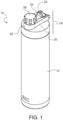
- FIG. 1 illustrates a perspective view of a hydration bottle having dual discharge openings, in accordance with an embodiment of the present invention.
- the hydration bottle 10 includes a bottle body 12 and a removable lid assembly 18.
- the hydration bottle 10 can also be referred to as a beverage bottle, a beverage container, a drink bottle, and/or a drink container.
- the bottle body 12 can also be referred to as a fluid container defining at least one chamber.
- the lid assembly 18 includes a first mouthpiece 22 ( FIG. 3 ) and a second mouthpiece 24 disposed over or on top of a base portion 20.
- the first mouthpiece 22 is enclosed within cap 28.
- the second mouthpiece 24 is in a closed position such that it is parallel to a top surface of the base portion 20. In the closed position, the opening 23 ( FIG. 5 ) of the second mouthpiece remains inaccessible.
- the second mouthpiece 24 further includes a tab or projection 25 disposed thereof.
- the lid assembly 18 further includes a pivotal mount 26 that accommodates both the first and second mouthpieces 22, 24.
- the pivotal mount 26 can also be referred to as a base or pedestal or support structure.
- the lid assembly 18 is secured to the mouth of the bottle body 12 by a threaded connection 19 ( FIG. 6 ). Threads are formed about the mouth of the bottle body 12 and cooperating threads are formed within the lid assembly 18 so that the lid assembly 18 may be threadably attached to and detached from the bottle body 12.
- Bottle body 12 may be made, manufactured, molded (e.g., injection, cold, or the like), or otherwise formed using various materials, including, but not limited to plastic, low density plastic, high density plastic, polycarbonate, polycarbonate without Bisphenol-A (or other endocrine disrupting compounds), polyvinyl chloride ("PVC"), stainless steel, wood, aluminum, polyester, copolyester, or any other type of organic or synthetic materials, alloys, or composites. Bottle body 12 may be transparent for purposes of describing various features.
- the bottle body 12 may be of any suitable material, including metal, plastic, glass, rubber and combinations thereof and may be insulated or un-insulated.
- suitable sizes i.e., capacities of drink fluid able to be received into the fluid container at one time
- suitable sizes i.e., capacities of drink fluid able to be received into the fluid container at one time
- bottle body 12 may be formed from any suitable material or combination of materials.
- suitable material(s) for the fluid container 12 include the durability of the material, the intended potable drink fluid, or types of drink fluids, that will be contained in the fluid container 12, the intended life, or period of use, of the hydration bottle 10, whether the fluid container 12 is intended to be refilled or otherwise reused, environmental concerns, whether the fluid container 12 is intended to resist being collapsed during use, whether the fluid container 12 is designed to permit a user to collapse the fluid container 12 inwardly when dispensing fluid therefrom, or to dispense drink fluid therefrom, whether the fluid container 12 is designed to be washed in a household dishwasher, etc.
- the material(s) may be selected so that the fluid container 12 will be transparent, or at least translucent, so that a user may see the contents of the fluid container 12, or at least the level of drink fluid within the fluid container 12, through the walls, or wall structure, of the fluid container 12.
- FIG. 2 illustrates a perspective view of the removable lid assembly of the hydration bottle of FIG. 1 , in accordance with an embodiment of the present invention.
- the removable lid assembly 18 can be connected to a straw 21.
- the second mouthpiece 24 can be connected to the straw 21.
- the second mouthpiece 24, in a closed position, can be parallel to axis A-A' extending through the pivotal mount 26.
- the pivotal mount 26 can have a substantially or generally U-shaped configuration.
- the pivotal mount 26 extends an entire length or diameter of the base portion 20.
- the pivotal mount 26 encompasses or encloses or surrounds the first mouthpiece 22 and the second mouthpiece 24 such that the first mouthpiece 22 is not visible or covered by cap 28, whereas the second mouthpiece 24 remains exposed.
- the pivotal mount 26 is formed over or on top of the base portion 20 of the lid assembly 18.
- the pivotal mount 26 engages flaps 45, as will be described in detail below with reference to FIG. 5 .
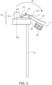
- FIG. 3 illustrates a perspective side view of the removable lid assembly, where the first mouthpiece is exposed, in accordance with an embodiment of the present invention.
- the pivotal mount 26 is opened in a flip motion "R1" (or swiveling motion) in order to expose the first mouthpiece 22.
- the pivotal mount 26 is pivoted about point “P.”
- Point “P” is configured to receive pins 38 ( FIG. 5 ) to secure the pivotal mount 26 to the lid assembly 18.
- the cap 28 remains fixedly attached to the pivotal mount 26 during the flip motion "R1.” It is contemplated that the cap 28 remains fixedly attached to the pivotal mount 26 at all times.
- the first mouthpiece 22 is fixed or non-swivelable. Thus, the first mouthpiece 22 remains perpendicular to axis B-B' at all times.
- the first mouthpiece 22 is a non-swiveling mouthpiece whereas the second mouthpiece 24 is a swiveling or movable mouthpiece.
- the first mouthpiece 22 is exposed, the second mouthpiece 24 remains in a closed position.
- a person using the lid assembly 18 on the bottle body 12 FIG. 1
- the first and second mouthpieces 22, 24 are independently operable and/or independently accessible. Thus, the user either uses and/or accesses one mouthpiece or the other, not both simultaneously or concurrently.
- the pivotal mount 26 moves in a swiveling manner over the second mouthpiece 24.
- the support member 29 FIG. 5
- the cap 28 and the support member 29 extend beyond the outer periphery or outer perimeter of the base 20 of the lid assembly 18.
- flip motion "R1" is directly over the second mouthpiece 24. In this position, the straw 21 is not accessible as the second mouthpiece 24 remains in a closed position.
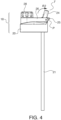
- FIG. 4 illustrates a perspective side view of the removable lid assembly, where the second mouthpiece is exposed, in accordance with an embodiment of the present invention.
- the pivotal mount 26 remains in a closed position, that is, the cap 28 of the pivotal mount 26 is positioned over the first mouthpiece 22 such that access to the first mouthpiece is prevented. Instead, the second mouthpiece 24 is flipped via flip motion "R2" to allow access to the person using the beverage bottle 10 ( FIG. 1 ).
- the second mouthpiece 24 swivels to a position "T" which is the furthest position the second mouthpiece 24 can be moved to due to the tab 25 contacting the base portion 20.
- the tab 25 determines how far the second mouthpiece 24 can be swiveled in the rightward direction.
- the tab 25 extends beyond an outer periphery or outer perimeter of the base portion 20 of the lid assembly 18.
- the first mouthpiece 22 remains in a closed position. In fact, the first mouthpiece 22 is not visible due to the cap 28. As a result, a person using the lid assembly 18 on the bottle body 12 ( FIG. 1 ) would only access one mouthpiece or opening or port at a time. It is contemplated that the first and second mouthpieces 22, 24 are independently operable and/or independently accessible. Thus, the user accesses and/or uses either one mouthpiece or the other, not both simultaneously or concurrently.
- the pivotal mount 26 enables the switching between the first and second mouthpieces 22, 24. For instance, when the pivotal mount 26 is in a first position (cap 28 over the first mouthpiece 22; FIG. 4 ), only the second mouthpiece 24 can be accessed. When the pivotal mount 26 is in a second position (pivoted in direction "R1"; FIG. 3 ), only the first mouthpiece 22 can be accessed. Thus, the first and second mouthpieces 22, 24 can be independently operated and/or accessed with respect to each other.
- FIG. 5 illustrates an exploded perspective view of the removable lid assembly, in accordance with an embodiment of the present invention.
- the exploded view clearly illustrates the mechanical components of the lid assembly 18 and their interrelations.
- the pivotal mount 26 defines a support member 29 having a first leg 26a and a second leg 26b extending therefrom.
- the first leg 26a remains parallel to the second leg 26b.
- the support member 29 is circular and defines a passage 29'.
- the distal ends of the first and second legs 26a, 26b define openings or apertures 27a.
- the pivotal mount 26 defines a substantially or generally U-shaped configuration.
- a washer 34 is configured to enable secure attachment between the support member 29 of the pivotal mount 26 and the cap 28.
- the second mouthpiece 24 includes a pair of lateral projections 33 on opposed ends thereof.
- the second mouthpiece 24 has an opening 23.
- the tab 25 of the second mouthpiece is further visualized.
- the tab 25 is vertically offset from the pair of lateral projections 33.
- the first mouthpiece 22 includes an opening 42 and is fixedly coupled or molded to the top surface of the base portion 20. Adjacent the first mouthpiece 22 is a pair of flaps 45.
- the flaps 45 have a tapered configuration such that the tapered portion is closer to the first mouthpiece 22.
- a threaded valve 36 is received within an aperture defined between the flaps 45.
- An O-ring seal 32 can be configured to facilitate secure engagement between the second mouthpiece 24 and the threaded valve 36.
- the lateral projections 33 of the second mouthpiece 24 are configured to be received within recesses 47 formed on inner sidewalls of the flaps 45.
- the recesses 47 are defined in the non-tapered section of the flaps 45.
- the tapered portion of the flaps 45 commences directly adjacent the recesses 47.
- the tapered flaps further include apertures 27b.
- the apertures 27b are defined at the non-tapered portion of the flaps 45. Stated differently, the apertures 27b are defined at the proximalmost end of the flaps 45.
- the apertures 27b are a pair of apertures configured to receive a pair of pins 38.
- Pins 38 are configured to couple the pivot mount 26 to the flaps 45 so that the second mouthpiece 24 is fixedly engaged to the base portion 20 adjacent the first mouthpiece 22.
- the pins 38 are received within the apertures 27b (of the flaps 45) and within the apertures 27a (of the pivot mount 26). Therefore, the pins 38 engage both apertures 27b and 27a.
- the pivotal mount 26 receives the first mouthpiece 22 within the passage 29' of the support member 29 and the legs 26a, 26b directly contact the outer surface or outer sidewalls of the flaps 45.
- the second mouthpiece 24 sits within or is confined within the boundaries set by the flaps 45.
- the second mouthpiece 24 does not directly contact the legs 26a, 26b of the pivotal mount 26.
- the flaps 45 separate the second mouthpiece 24 from the pivotal mount 26. Stated differently, the flaps 45 prevent the second mouthpiece 24 from directly contacting the legs 26a, 26b of the pivotal mount 26. It is contemplated that the sidewall of the cap 28 may contact the opening 23 of the second mouthpiece 24.
- a seal ring 30 can be positioned within the base 20 of the lid assembly 18 to facilitate engagement between the lid assembly 18 and the bottle body 12 of the beverage bottle 10 ( FIG. 1 ).
- a straw 21 can be releasably connected to the base portion 20 such that the straw 21 can be accessed via opening 23 of the second mouthpiece 24.
- FIG. 6 illustrates a cross-sectional view of the removable lid assembly, in accordance with an embodiment of the present invention.
- Lid assembly 18 may be joined to the bottle body 12 ( FIG. 1 ) using various techniques including, but not limited to, continuous and non-continuous screw threads, adhesives, pressure-based coupling mechanisms (e.g., ridges), or others.
- lid assembly 18 may be rotated to engage screw threads (not shown) disposed on bottle body 12 with screw thread channels or canals (hereafter "channels") 19 to create a seal that may be hermetic and watertight.
- screw thread channels may refer to a screw thread or set of screw threads that, when engaged with a corresponding screw thread or set of screw threads creates a seal between two elements providing, in some examples, an air-tight or water-tight (e.g., hermetic) seal.
- the cross-sectional view further illustrates the first mouthpiece 22 and its positional relationship to the second mouthpiece 24.
- the opening 42 of the first mouthpiece is perpendicular to the opening of the second mouthpiece 24.
- threads 48 of the cap 28 are shown that are configured to securely cover the opening 42 of the first mouthpiece 22.
- beverage bottle 10 and the above-described elements may be varied in function, structure, shape, design, implementation, configuration, or other aspects without limitation to the descriptions provided.
- a hydration bottle or beverage bottle including dual openings or dual ports or dual mouthpieces.
- One mouthpiece is fixed (or non-swivelable) and the other mouthpiece is swivelable (e.g., can be actuated in a flip motion).
- the first mouthpiece is configured to be independently operable and/or independently accessible with respect to the second mouthpiece. In other words, the first and second mouthpieces cannot be accessed at the same time (concurrently or simultaneously). Thus, a user can access either the first mouthpiece or the second mouthpiece.
- Such operation is enabled by a pivotal mount or pedestal.
- the pivotal mount flips to an open position to allow access to the first mouthpiece and flips to a closed position to allow the second mouthpiece to be flipped open.
- the pivotal mount pivots about pins placed at a proximalmost end of tapered flaps.
- the tapered flaps are positioned directly between the second mouthpiece and the pivotal mount to prevent direct contact therebetween.
- the second mouthpiece rests within recesses formed on an inner surface of the tapered flaps.
- the first mouthpiece is vertically offset from the second mouthpiece.
- the first and second mouthpieces are placed or positioned or disposed on a base portion of the lid assembly.
- the pivotal mount has a substantially or generally U-shaped configuration shaped to facilitate independent access to the first and second mouthpieces.
Landscapes
- Engineering & Computer Science (AREA)
- Mechanical Engineering (AREA)
- Closures For Containers (AREA)
Description
- The present invention relates generally to hydration and fluid carrying devices, and more specifically, to a hydration bottle having dual openings independently operable and/or accessible with respect to each other.
- Conventional hydration devices such as water bottles are useful for various purposes in activities such as athletic, outdoor, recreational, or other uses. Typically, water bottles are designed for a user to carry water, electrolytic fluid replacement drinks, or any type of liquid or, in some cases, powders or other materials. Conventionally, these bottles are formed from plastic and include a cap. Some conventional drink bottles include a threaded or other neck from which a user drinks fluid contained in the drink bottle after removal of the cap. Some conventional drink bottles include a spout, or nozzle, from which the drink fluid may be drawn from the drink bottle without removing the cap of the drink bottle. Conventional spouts include straws and rigid spouts having an outlet through which drink fluid may flow. Other conventional drink bottles require the cap to be completely removed to permit drink fluid to be accessed from the drink bottle.
- A prior art dual-opening type bottle cap for a beverage container is known from
CN 209634978 . - In accordance with an embodiment, a hydration bottle as recited by claim 1 is provided.
- Preferable features are presented in the dependent claims.
- It should be noted that the exemplary embodiments are described with reference to different subject-matters.
- These and other features and advantages will become apparent from the following detailed description of illustrative embodiments thereof, which is to be read in connection with the accompanying drawings.
- The invention will provide details in the following description of preferred embodiments with reference to the following figures wherein:
-
FIG. 1 illustrates a perspective view of a hydration bottle having dual discharge openings, in accordance with an embodiment of the present invention; -
FIG. 2 illustrates a perspective view of the removable lid assembly of the hydration bottle ofFIG. 1 , in accordance with an embodiment of the present invention; -
FIG. 3 illustrates a perspective side view of the removable lid assembly, where the first mouthpiece is exposed, in accordance with an embodiment of the present invention; -
FIG. 4 illustrates a perspective side view of the removable lid assembly, where the second mouthpiece is exposed, in accordance with an embodiment of the present invention; -
FIG. 5 illustrates an exploded perspective view of the removable lid assembly, in accordance with an embodiment of the present invention; and -
FIG. 6 illustrates a cross-sectional view of the removable lid assembly, in accordance with an embodiment of the present invention. - Throughout the drawings, same or similar reference numerals represent the same or similar elements.
- Embodiments in accordance with the present invention provide for a hydration bottle having dual openings independently operable and/or accessible with respect to each other.
- Personal beverage bottles are becoming ever more popular and have moved beyond the common beverage bottle packed with a school lunch or in a lunch box. Gyms are filled with members exercising, and many members bring their own beverage bottles for hydration. Hikers, bikers, walkers, commuters, tourists and many others carry beverage bottles as they go about their business. An increasingly common feature of the beverage bottles is a drink nozzle or spout that offers the ability to drink from the bottle without complete removal of the lid from the bottle.
- The exemplary embodiments of the present invention introduce drink bottles and drink containers applicable to the hydration field, and are specifically applicable to portable bottles and similar containers from which users may selectively drink potable drink fluid. The hydration bottles of the exemplary embodiments of the present invention include a first opening or port or mouthpiece and a second opening or port or mouthpiece. The first mouthpiece is fixed on a base portion of a lid assembly, whereas the second mouthpiece is swivelable or movable or non-fixed. A pivotal mount or pedestal having a support member with two legs extending therefrom enables a user to selectively use either the first mouthpiece or the second mouthpiece. Stated differently, the pivotal mount enables independent operation and/or accessibility of the first and second mouthpieces.
- It is to be understood that the present invention will be described in terms of a given illustrative architecture; however, other architectures, structures, substrate materials and process features and steps/blocks can be varied within the scope of the present invention as long as they fall within the scope of the claims. It should be noted that certain features cannot be shown in all figures for the sake of clarity. This is not intended to be interpreted as a limitation of any particular embodiment, or illustration, or scope of the claims.
-
FIG. 1 illustrates a perspective view of a hydration bottle having dual discharge openings, in accordance with an embodiment of the present invention. - The
hydration bottle 10 includes abottle body 12 and aremovable lid assembly 18. Thehydration bottle 10 can also be referred to as a beverage bottle, a beverage container, a drink bottle, and/or a drink container. Thebottle body 12 can also be referred to as a fluid container defining at least one chamber. - The
lid assembly 18 includes a first mouthpiece 22 (FIG. 3 ) and asecond mouthpiece 24 disposed over or on top of abase portion 20. Thefirst mouthpiece 22 is enclosed withincap 28. Thesecond mouthpiece 24 is in a closed position such that it is parallel to a top surface of thebase portion 20. In the closed position, the opening 23 (FIG. 5 ) of the second mouthpiece remains inaccessible. Thesecond mouthpiece 24 further includes a tab orprojection 25 disposed thereof. Thelid assembly 18 further includes apivotal mount 26 that accommodates both the first andsecond mouthpieces pivotal mount 26 can also be referred to as a base or pedestal or support structure. - The
lid assembly 18 is secured to the mouth of thebottle body 12 by a threaded connection 19 (FIG. 6 ). Threads are formed about the mouth of thebottle body 12 and cooperating threads are formed within thelid assembly 18 so that thelid assembly 18 may be threadably attached to and detached from thebottle body 12. -
Bottle body 12 may be made, manufactured, molded (e.g., injection, cold, or the like), or otherwise formed using various materials, including, but not limited to plastic, low density plastic, high density plastic, polycarbonate, polycarbonate without Bisphenol-A (or other endocrine disrupting compounds), polyvinyl chloride ("PVC"), stainless steel, wood, aluminum, polyester, copolyester, or any other type of organic or synthetic materials, alloys, or composites.Bottle body 12 may be transparent for purposes of describing various features. - The
bottle body 12 may be of any suitable material, including metal, plastic, glass, rubber and combinations thereof and may be insulated or un-insulated. Illustrative, non-exclusive examples of suitable sizes (i.e., capacities of drink fluid able to be received into the fluid container at one time) forfluid container 12 include 4 oz. (118 ml), 6 oz. (177 ml), 8 oz. (237 ml), 10 oz. (296 ml), 12 oz. (355 ml), 16 oz. (473 ml), 20 oz. (591 ml), 24 oz. (710 ml), 32 oz. (946 ml), 36 oz. (1,065 ml), 0.5 liters, 0.7 liters, 1 liter, 1.5 liters, 6-11 oz. (177-325 ml), 12-19 oz. (355-562 ml), 19-25 oz. (562-739 ml), 12-36 oz. (355-1,065 ml), 25-36 oz (739-1,065 ml), and 10-70 oz. (296-2,070 ml) (with these illustrative examples referring to fluid ounces of drink fluid that may be poured in one filling into an empty fluid container). It is within the scope of the present disclosure that containers having different sizes, including sizes that are smaller than, larger than, or within the illustrative sizes and/or ranges presented above, may be used without departing from the scope of the present disclosure. - Moreover,
bottle body 12 may be formed from any suitable material or combination of materials. Non-exclusive examples of factors that may be (but are not required to be) considered when selecting material(s) for thefluid container 12 include the durability of the material, the intended potable drink fluid, or types of drink fluids, that will be contained in thefluid container 12, the intended life, or period of use, of thehydration bottle 10, whether thefluid container 12 is intended to be refilled or otherwise reused, environmental concerns, whether thefluid container 12 is intended to resist being collapsed during use, whether thefluid container 12 is designed to permit a user to collapse thefluid container 12 inwardly when dispensing fluid therefrom, or to dispense drink fluid therefrom, whether thefluid container 12 is designed to be washed in a household dishwasher, etc. In some embodiments, it may be desirable for the material(s) to be selected so that thefluid container 12 will be transparent, or at least translucent, so that a user may see the contents of thefluid container 12, or at least the level of drink fluid within thefluid container 12, through the walls, or wall structure, of thefluid container 12. -
FIG. 2 illustrates a perspective view of the removable lid assembly of the hydration bottle ofFIG. 1 , in accordance with an embodiment of the present invention. - The
removable lid assembly 18 can be connected to astraw 21. In one instance, thesecond mouthpiece 24 can be connected to thestraw 21. Thesecond mouthpiece 24, in a closed position, can be parallel to axis A-A' extending through thepivotal mount 26. - The
pivotal mount 26 can have a substantially or generally U-shaped configuration. Thepivotal mount 26 extends an entire length or diameter of thebase portion 20. Thepivotal mount 26 encompasses or encloses or surrounds thefirst mouthpiece 22 and thesecond mouthpiece 24 such that thefirst mouthpiece 22 is not visible or covered bycap 28, whereas thesecond mouthpiece 24 remains exposed. Thepivotal mount 26 is formed over or on top of thebase portion 20 of thelid assembly 18. Thepivotal mount 26 engagesflaps 45, as will be described in detail below with reference toFIG. 5 . -
FIG. 3 illustrates a perspective side view of the removable lid assembly, where the first mouthpiece is exposed, in accordance with an embodiment of the present invention. - The
pivotal mount 26 is opened in a flip motion "R1" (or swiveling motion) in order to expose thefirst mouthpiece 22. Thepivotal mount 26 is pivoted about point "P." Point "P" is configured to receive pins 38 (FIG. 5 ) to secure thepivotal mount 26 to thelid assembly 18. Thecap 28 remains fixedly attached to thepivotal mount 26 during the flip motion "R1." It is contemplated that thecap 28 remains fixedly attached to thepivotal mount 26 at all times. - The
first mouthpiece 22 is fixed or non-swivelable. Thus, thefirst mouthpiece 22 remains perpendicular to axis B-B' at all times. Thefirst mouthpiece 22 is a non-swiveling mouthpiece whereas thesecond mouthpiece 24 is a swiveling or movable mouthpiece. When thefirst mouthpiece 22 is exposed, thesecond mouthpiece 24 remains in a closed position. As a result, a person using thelid assembly 18 on the bottle body 12 (FIG. 1 ) would only access one mouthpiece or opening or port at a time. It is contemplated that the first andsecond mouthpieces - It is noted that the
pivotal mount 26 moves in a swiveling manner over thesecond mouthpiece 24. In other words, the support member 29 (FIG. 5 ) with thecap 28 extends directly over thesecond mouthpiece 24 such that it rests in the inverted position "I." In the inverted position "I," thecap 28 and thesupport member 29 extend beyond the outer periphery or outer perimeter of thebase 20 of thelid assembly 18. Thus, flip motion "R1" is directly over thesecond mouthpiece 24. In this position, thestraw 21 is not accessible as thesecond mouthpiece 24 remains in a closed position. -
FIG. 4 illustrates a perspective side view of the removable lid assembly, where the second mouthpiece is exposed, in accordance with an embodiment of the present invention. - The
pivotal mount 26 remains in a closed position, that is, thecap 28 of thepivotal mount 26 is positioned over thefirst mouthpiece 22 such that access to the first mouthpiece is prevented. Instead, thesecond mouthpiece 24 is flipped via flip motion "R2" to allow access to the person using the beverage bottle 10 (FIG. 1 ). Thesecond mouthpiece 24 swivels to a position "T" which is the furthest position thesecond mouthpiece 24 can be moved to due to thetab 25 contacting thebase portion 20. Thus, thetab 25 determines how far thesecond mouthpiece 24 can be swiveled in the rightward direction. Thetab 25 extends beyond an outer periphery or outer perimeter of thebase portion 20 of thelid assembly 18. - As a result, when the
second mouthpiece 24 is exposed, thefirst mouthpiece 22 remains in a closed position. In fact, thefirst mouthpiece 22 is not visible due to thecap 28. As a result, a person using thelid assembly 18 on the bottle body 12 (FIG. 1 ) would only access one mouthpiece or opening or port at a time. It is contemplated that the first andsecond mouthpieces - Therefore, in operation, in
FIG. 3 , the user flips thepivotal mount 26 to access thefirst mouthpiece 22, whereas, in operation, inFIG. 4 , the user flips thesecond mouthpiece 24 to access themouthpiece 24. Thus, when one port is open, the other remains closed, and vice versa. Moreover, thepivotal mount 26 enables the switching between the first andsecond mouthpieces pivotal mount 26 is in a first position (cap 28 over thefirst mouthpiece 22;FIG. 4 ), only thesecond mouthpiece 24 can be accessed. When thepivotal mount 26 is in a second position (pivoted in direction "R1";FIG. 3 ), only thefirst mouthpiece 22 can be accessed. Thus, the first andsecond mouthpieces -
FIG. 5 illustrates an exploded perspective view of the removable lid assembly, in accordance with an embodiment of the present invention. - The exploded view clearly illustrates the mechanical components of the
lid assembly 18 and their interrelations. - The
pivotal mount 26 defines asupport member 29 having afirst leg 26a and asecond leg 26b extending therefrom. Thefirst leg 26a remains parallel to thesecond leg 26b. Thesupport member 29 is circular and defines a passage 29'. The distal ends of the first andsecond legs apertures 27a. Thepivotal mount 26 defines a substantially or generally U-shaped configuration. Awasher 34 is configured to enable secure attachment between thesupport member 29 of thepivotal mount 26 and thecap 28. - The
second mouthpiece 24 includes a pair oflateral projections 33 on opposed ends thereof. Thesecond mouthpiece 24 has anopening 23. Thetab 25 of the second mouthpiece is further visualized. Thetab 25 is vertically offset from the pair oflateral projections 33. - The
first mouthpiece 22 includes anopening 42 and is fixedly coupled or molded to the top surface of thebase portion 20. Adjacent thefirst mouthpiece 22 is a pair offlaps 45. Theflaps 45 have a tapered configuration such that the tapered portion is closer to thefirst mouthpiece 22. A threadedvalve 36 is received within an aperture defined between theflaps 45. An O-ring seal 32 can be configured to facilitate secure engagement between thesecond mouthpiece 24 and the threadedvalve 36. Thelateral projections 33 of thesecond mouthpiece 24 are configured to be received withinrecesses 47 formed on inner sidewalls of theflaps 45. Therecesses 47 are defined in the non-tapered section of theflaps 45. The tapered portion of theflaps 45 commences directly adjacent therecesses 47. - The tapered flaps further include
apertures 27b. Theapertures 27b are defined at the non-tapered portion of theflaps 45. Stated differently, theapertures 27b are defined at the proximalmost end of theflaps 45. Theapertures 27b are a pair of apertures configured to receive a pair ofpins 38.Pins 38 are configured to couple thepivot mount 26 to theflaps 45 so that thesecond mouthpiece 24 is fixedly engaged to thebase portion 20 adjacent thefirst mouthpiece 22. Thepins 38 are received within theapertures 27b (of the flaps 45) and within theapertures 27a (of the pivot mount 26). Therefore, thepins 38 engage bothapertures - Further, the
pivotal mount 26 receives thefirst mouthpiece 22 within the passage 29' of thesupport member 29 and thelegs flaps 45. As a result, thesecond mouthpiece 24 sits within or is confined within the boundaries set by theflaps 45. Thesecond mouthpiece 24 does not directly contact thelegs pivotal mount 26. Theflaps 45 separate thesecond mouthpiece 24 from thepivotal mount 26. Stated differently, theflaps 45 prevent thesecond mouthpiece 24 from directly contacting thelegs pivotal mount 26. It is contemplated that the sidewall of thecap 28 may contact theopening 23 of thesecond mouthpiece 24. - Additionally, a
seal ring 30 can be positioned within thebase 20 of thelid assembly 18 to facilitate engagement between thelid assembly 18 and thebottle body 12 of the beverage bottle 10 (FIG. 1 ). - A
straw 21 can be releasably connected to thebase portion 20 such that thestraw 21 can be accessed via opening 23 of thesecond mouthpiece 24. -
FIG. 6 illustrates a cross-sectional view of the removable lid assembly, in accordance with an embodiment of the present invention. -
Lid assembly 18 may be joined to the bottle body 12 (FIG. 1 ) using various techniques including, but not limited to, continuous and non-continuous screw threads, adhesives, pressure-based coupling mechanisms (e.g., ridges), or others. For example,lid assembly 18 may be rotated to engage screw threads (not shown) disposed onbottle body 12 with screw thread channels or canals (hereafter "channels") 19 to create a seal that may be hermetic and watertight. In some examples, reference to screw thread channels may refer to a screw thread or set of screw threads that, when engaged with a corresponding screw thread or set of screw threads creates a seal between two elements providing, in some examples, an air-tight or water-tight (e.g., hermetic) seal. - The cross-sectional view further illustrates the
first mouthpiece 22 and its positional relationship to thesecond mouthpiece 24. Theopening 42 of the first mouthpiece is perpendicular to the opening of thesecond mouthpiece 24. - Additionally,
threads 48 of thecap 28 are shown that are configured to securely cover theopening 42 of thefirst mouthpiece 22. - In other examples,
beverage bottle 10 and the above-described elements may be varied in function, structure, shape, design, implementation, configuration, or other aspects without limitation to the descriptions provided. - In summary, a hydration bottle or beverage bottle is presented including dual openings or dual ports or dual mouthpieces. One mouthpiece is fixed (or non-swivelable) and the other mouthpiece is swivelable (e.g., can be actuated in a flip motion). The first mouthpiece is configured to be independently operable and/or independently accessible with respect to the second mouthpiece. In other words, the first and second mouthpieces cannot be accessed at the same time (concurrently or simultaneously). Thus, a user can access either the first mouthpiece or the second mouthpiece. Such operation is enabled by a pivotal mount or pedestal. The pivotal mount flips to an open position to allow access to the first mouthpiece and flips to a closed position to allow the second mouthpiece to be flipped open. The pivotal mount pivots about pins placed at a proximalmost end of tapered flaps. The tapered flaps are positioned directly between the second mouthpiece and the pivotal mount to prevent direct contact therebetween. The second mouthpiece rests within recesses formed on an inner surface of the tapered flaps. The first mouthpiece is vertically offset from the second mouthpiece. The first and second mouthpieces are placed or positioned or disposed on a base portion of the lid assembly. The pivotal mount has a substantially or generally U-shaped configuration shaped to facilitate independent access to the first and second mouthpieces.
- While there have been shown, described and pointed out fundamental novel features of the present principles, it will be understood that various omissions, substitutions and changes in the form and details of the methods described and devices illustrated, and in their operation, may be made by those skilled in the art without departing from the scope of the invention as set out in the appended claims.
- It should also be understood that the example embodiments disclosed and taught herein are susceptible to numerous and various modifications and alternative forms. Thus, the use of a singular term, such as, but not limited to, "a" and the like, is not intended as limiting of the number of items. Furthermore, the naming conventions for the various components, functions, parameters, thresholds, and other elements used herein are provided as examples, and can be given a different name or label. The use of the term "or" is not limited to exclusive "or" but can also mean "and/or".
- Having described preferred embodiments, which serve to illustrate various concepts, structures and techniques that are the subject of this patent, it will now become apparent to those of ordinary skill in the art that other embodiments incorporating these concepts, structures and techniques may be used.
- Accordingly, it is submitted that that scope of the patent should not be limited to the described embodiments but rather should be limited only by the scope of the following claims.
Claims (11)
- A hydration bottle (10) comprising:a fluid container (12); anda lid assembly (18) configured to be releasably engaged to the fluid container (12), the lid assembly having a first mouthpiece (22) and a second mouthpiece (24) independently accessible with respect to each other,wherein the lid assembly includes a pivotal mount (26) having two legs (26a, 26b) extending from a support member (29) to form a generally U-shaped configuration, the support member (29) defining a passage (29'), andwherein the passage (29') of the support member of the pivotal mount (26) is configured to receive the first mouthpiece (22).
- The hydration bottle of claim 1, wherein the passage of the support member of the pivotal mount has a cap (28) fixedly disposed thereof.
- The hydration bottle of any preceding claim, wherein the first mouthpiece is a non-swiveling mouthpiece and the second mouthpiece is a swiveling mouthpiece.
- The hydration bottle of claim 3, wherein the second mouthpiece is connected to a straw (21) extending within the fluid container.
- The hydration bottle of any preceding claim, wherein the lid assembly comprises a base portion (20) defining a circumferentially threaded configuration (19) on an inner surface thereof.
- The hydration bottle of any preceding claim, wherein the pivotal mount pivots directly over the second mouthpiece to expose the first mouthpiece.
- The hydration bottle of any preceding claim, wherein the second mouthpiece is positioned within the confines of the two legs of the pivotal mount.
- The hydration bottle of any preceding claim, wherein the second mouthpiece includes a pair of lateral projections (33) on opposed ends thereof.
- The hydration bottle of claim 8, wherein the pair of lateral projections of the second mouthpiece are adapted to engage a pair of tapered flaps (45) disposed on the base portion of the lid assembly.
- The hydration bottle of claim 9, wherein an outer surface of the pair of tapered flaps directly contacts an inner surface of the two legs of the pivot mount.
- The hydration bottle of claim 10, wherein the pair of tapered flaps define apertures (27b) for receiving pins (38), the pins configured to fixedly attach the pair of tapered flaps to the pivot mount.
Applications Claiming Priority (1)
| Application Number | Priority Date | Filing Date | Title |
|---|---|---|---|
| US17/350,573 US11639253B2 (en) | 2021-06-17 | 2021-06-17 | Multifunctional bottle lid assembly |
Publications (3)
| Publication Number | Publication Date |
|---|---|
| EP4104710A1 EP4104710A1 (en) | 2022-12-21 |
| EP4104710B1 true EP4104710B1 (en) | 2024-08-07 |
| EP4104710C0 EP4104710C0 (en) | 2024-08-07 |
Family
ID=82115961
Family Applications (1)
| Application Number | Title | Priority Date | Filing Date |
|---|---|---|---|
| EP22179504.0A Active EP4104710B1 (en) | 2021-06-17 | 2022-06-17 | Multifunctional bottle lid assembly |
Country Status (4)
| Country | Link |
|---|---|
| US (1) | US11639253B2 (en) |
| EP (1) | EP4104710B1 (en) |
| CN (1) | CN115489868B (en) |
| AU (1) | AU2022203115A1 (en) |
Families Citing this family (9)
| Publication number | Priority date | Publication date | Assignee | Title |
|---|---|---|---|---|
| EP3743349A4 (en) * | 2018-01-26 | 2021-10-20 | Strix (USA), Inc. | LID FOR LIQUID CONTAINER AND DEVICE AND METHOD OF USE |
| USD988787S1 (en) * | 2019-08-27 | 2023-06-13 | Runway Blue, Llc | Container |
| USD1111828S1 (en) | 2021-04-30 | 2026-02-10 | Gourmet Home Products, Llc | Combined container and lid |
| TWM617443U (en) * | 2021-06-08 | 2021-09-21 | 羽鈦有限公司 | Beverage container and cover body component thereof |
| USD1049762S1 (en) * | 2022-03-31 | 2024-11-05 | Gourmet Home Products, Llc | Dual opening lid for a drink container |
| CN223860527U (en) * | 2022-09-08 | 2026-02-03 | 安捷仕环球资源(香港)有限公司 | Cap assembly for container |
| CN116889329A (en) * | 2022-09-19 | 2023-10-17 | 广东木森日用品有限公司 | Cup lid with double drinking mouth and mug provided with the cup lid |
| US12600536B2 (en) * | 2023-11-30 | 2026-04-14 | Personalizations, Inc. | Dual function lid for mug or other drinkware |
| US20260015135A1 (en) * | 2024-07-10 | 2026-01-15 | Camelbak Products, Llc | Cap assembly for drink containers |
Family Cites Families (33)
| Publication number | Priority date | Publication date | Assignee | Title |
|---|---|---|---|---|
| US2844267A (en) | 1956-11-05 | 1958-07-22 | Petriccione Peter | Combined drinking straw and bottle cap |
| US3042701A (en) | 1959-10-21 | 1962-07-03 | Monsanto Chemicals | Organic phosphates |
| US4976364A (en) | 1990-01-30 | 1990-12-11 | Solomon Stanley B | Cap and straw assembly for a water bottle |
| US5158191A (en) | 1991-03-01 | 1992-10-27 | Plastic Processing Corporation | Dual bottle container having a dual outlet cap |
| US5244113A (en) * | 1992-08-24 | 1993-09-14 | Northwestern Bottle Company | Container lid assembly |
| JPH09183448A (en) | 1995-07-22 | 1997-07-15 | Yoshino Kogyosho Co Ltd | Lid for drink container with induction tube |
| US20030168455A1 (en) * | 2002-03-08 | 2003-09-11 | Zettle Jeffrey J. | Container lid with selectable opening and valve assembly for retaining a valve |
| US7533783B2 (en) | 2005-04-11 | 2009-05-19 | Camelbak Products, Llc | Drink bottles with bite-actuated mouthpieces |
| US20070029334A1 (en) | 2005-08-02 | 2007-02-08 | Bagley Perry S | Beverage containers and accessories with integrated straw |
| US8408410B2 (en) | 2009-01-21 | 2013-04-02 | Erez Raman | Reusable drinking straw holder with bottle neck securing assembly |
| US8365941B2 (en) | 2009-05-15 | 2013-02-05 | David James Mayer | Dual-capped hydration bottle |
| USD626837S1 (en) | 2010-04-16 | 2010-11-09 | Runway Blue, Llc | Bottle closure with flip top |
| TWM399845U (en) | 2010-07-26 | 2011-03-11 | Taiwan Vertex Production Corp | Rotary water stop bottle cap |
| US20120234789A1 (en) * | 2010-11-24 | 2012-09-20 | Cool Gear International, Llc | Caps and containers |
| US8550269B2 (en) | 2011-06-08 | 2013-10-08 | Thermos L.L.C. | Drink bottle and lid with cover for drink spout |
| US8689989B2 (en) | 2012-02-28 | 2014-04-08 | Thermos L.L.C. | Drink bottle and lid with button release at back of lid |
| US9233217B2 (en) * | 2012-10-17 | 2016-01-12 | Jason S. Jones | Personal vapor device having disguised appearance |
| US9120599B2 (en) * | 2013-11-25 | 2015-09-01 | Ellis N. Shamoon | Dual chamber drink container |
| US9392892B2 (en) * | 2014-10-17 | 2016-07-19 | Aegis Global Resources (Hk) Limited | Lid assembly and drinking container comprising the same |
| KR20160003984U (en) * | 2015-05-12 | 2016-11-22 | 옌-호 루 | Cap assembly |
| US20160355305A1 (en) | 2015-06-03 | 2016-12-08 | Tsi Manufacturing, Llc | Multi-drink bottles |
| US20170129665A1 (en) * | 2015-11-09 | 2017-05-11 | Patrick J. Rolfes | Pod shaker bottle with lid |
| CN208160500U (en) | 2017-03-13 | 2018-11-30 | 上海雨豪日用制品有限公司 | Cup and its cup lid and housing unit |
| USD830118S1 (en) | 2017-04-10 | 2018-10-09 | O2Cool, Llc | Bottle cap |
| US10518282B2 (en) * | 2017-04-10 | 2019-12-31 | O2Cool, Llc | Drink and misting bottle with trigger lock |
| US10159368B2 (en) * | 2017-05-17 | 2018-12-25 | Shin-Shuoh Lin | Multifunctional mug cap with a sipper and straw |
| USD856065S1 (en) | 2017-06-08 | 2019-08-13 | O2Cool, Llc | Bottle cap |
| USD874214S1 (en) | 2017-07-07 | 2020-02-04 | O2Cool, Llc | Bottle cap |
| US20190062006A1 (en) | 2017-08-24 | 2019-02-28 | O2Cool, Llc | Bottle Closure |
| EP3743349A4 (en) * | 2018-01-26 | 2021-10-20 | Strix (USA), Inc. | LID FOR LIQUID CONTAINER AND DEVICE AND METHOD OF USE |
| US10512347B1 (en) * | 2018-08-28 | 2019-12-24 | Zak Designs, Inc. | Dual-dispensing lid |
| CN209634978U (en) | 2018-12-29 | 2019-11-15 | (美商)察可汗设计公司 | Double-neck closures for beverage containers |
| TWM582333U (en) * | 2019-04-08 | 2019-08-21 | 于春明 | Multi-functional dispensing water bottle |
-
2021
- 2021-06-17 US US17/350,573 patent/US11639253B2/en active Active
-
2022
- 2022-05-10 AU AU2022203115A patent/AU2022203115A1/en active Pending
- 2022-06-08 CN CN202210643754.3A patent/CN115489868B/en active Active
- 2022-06-17 EP EP22179504.0A patent/EP4104710B1/en active Active
Also Published As
| Publication number | Publication date |
|---|---|
| EP4104710A1 (en) | 2022-12-21 |
| US20220402663A1 (en) | 2022-12-22 |
| CN115489868A (en) | 2022-12-20 |
| AU2022203115A1 (en) | 2023-01-19 |
| EP4104710C0 (en) | 2024-08-07 |
| US11639253B2 (en) | 2023-05-02 |
| CN115489868B (en) | 2025-11-21 |
Similar Documents
| Publication | Publication Date | Title |
|---|---|---|
| EP4104710A1 (en) | Multifunctional bottle lid assembly | |
| US20250326533A1 (en) | Water bottle | |
| US10737845B2 (en) | Liquid-dispensing container with multiple-position selector | |
| US12035825B2 (en) | Lid for a container | |
| RU2582467C2 (en) | Hand-held mixing vessel | |
| CA3125455C (en) | Lid for a container | |
| US8464895B2 (en) | Beverage container with one-handed operation | |
| US20150201775A1 (en) | Lid for a container | |
| KR102050965B1 (en) | Tumbler | |
| US20240366005A1 (en) | Lid for a container | |
| US7806298B2 (en) | Multi-compartment dispensing container | |
| CN215837600U (en) | Bottle container with large-caliber inlet | |
| CN208048529U (en) | A kind of refluence pot | |
| JP2024115015A (en) | Water Bottle | |
| KR200371223Y1 (en) | A cap of liquid bottle | |
| JP2003128111A (en) | Spouting device for liquid vessel | |
| HK1180201A (en) | Beverage container with one-handed operation | |
| HK1231343B (en) | Lid for a container |
Legal Events
| Date | Code | Title | Description |
|---|---|---|---|
| PUAI | Public reference made under article 153(3) epc to a published international application that has entered the european phase |
Free format text: ORIGINAL CODE: 0009012 |
|
| STAA | Information on the status of an ep patent application or granted ep patent |
Free format text: STATUS: THE APPLICATION HAS BEEN PUBLISHED |
|
| AK | Designated contracting states |
Kind code of ref document: A1 Designated state(s): AL AT BE BG CH CY CZ DE DK EE ES FI FR GB GR HR HU IE IS IT LI LT LU LV MC MK MT NL NO PL PT RO RS SE SI SK SM TR |
|
| STAA | Information on the status of an ep patent application or granted ep patent |
Free format text: STATUS: REQUEST FOR EXAMINATION WAS MADE |
|
| 17P | Request for examination filed |
Effective date: 20230620 |
|
| RBV | Designated contracting states (corrected) |
Designated state(s): AL AT BE BG CH CY CZ DE DK EE ES FI FR GB GR HR HU IE IS IT LI LT LU LV MC MK MT NL NO PL PT RO RS SE SI SK SM TR |
|
| GRAP | Despatch of communication of intention to grant a patent |
Free format text: ORIGINAL CODE: EPIDOSNIGR1 |
|
| STAA | Information on the status of an ep patent application or granted ep patent |
Free format text: STATUS: GRANT OF PATENT IS INTENDED |
|
| INTG | Intention to grant announced |
Effective date: 20240122 |
|
| GRAS | Grant fee paid |
Free format text: ORIGINAL CODE: EPIDOSNIGR3 |
|
| GRAA | (expected) grant |
Free format text: ORIGINAL CODE: 0009210 |
|
| STAA | Information on the status of an ep patent application or granted ep patent |
Free format text: STATUS: THE PATENT HAS BEEN GRANTED |
|
| AK | Designated contracting states |
Kind code of ref document: B1 Designated state(s): AL AT BE BG CH CY CZ DE DK EE ES FI FR GB GR HR HU IE IS IT LI LT LU LV MC MK MT NL NO PL PT RO RS SE SI SK SM TR |
|
| REG | Reference to a national code |
Ref country code: GB Ref legal event code: FG4D |
|
| REG | Reference to a national code |
Ref country code: CH Ref legal event code: EP |
|
| REG | Reference to a national code |
Ref country code: DE Ref legal event code: R096 Ref document number: 602022005109 Country of ref document: DE |
|
| REG | Reference to a national code |
Ref country code: IE Ref legal event code: FG4D |
|
| U01 | Request for unitary effect filed |
Effective date: 20240807 |
|
| U07 | Unitary effect registered |
Designated state(s): AT BE BG DE DK EE FI FR IT LT LU LV MT NL PT SE SI Effective date: 20240813 |
|
| PG25 | Lapsed in a contracting state [announced via postgrant information from national office to epo] |
Ref country code: NO Free format text: LAPSE BECAUSE OF FAILURE TO SUBMIT A TRANSLATION OF THE DESCRIPTION OR TO PAY THE FEE WITHIN THE PRESCRIBED TIME-LIMIT Effective date: 20241107 |
|
| PG25 | Lapsed in a contracting state [announced via postgrant information from national office to epo] |
Ref country code: PL Free format text: LAPSE BECAUSE OF FAILURE TO SUBMIT A TRANSLATION OF THE DESCRIPTION OR TO PAY THE FEE WITHIN THE PRESCRIBED TIME-LIMIT Effective date: 20240807 Ref country code: GR Free format text: LAPSE BECAUSE OF FAILURE TO SUBMIT A TRANSLATION OF THE DESCRIPTION OR TO PAY THE FEE WITHIN THE PRESCRIBED TIME-LIMIT Effective date: 20241108 |
|
| PG25 | Lapsed in a contracting state [announced via postgrant information from national office to epo] |
Ref country code: IS Free format text: LAPSE BECAUSE OF FAILURE TO SUBMIT A TRANSLATION OF THE DESCRIPTION OR TO PAY THE FEE WITHIN THE PRESCRIBED TIME-LIMIT Effective date: 20241207 |
|
| PG25 | Lapsed in a contracting state [announced via postgrant information from national office to epo] |
Ref country code: HR Free format text: LAPSE BECAUSE OF FAILURE TO SUBMIT A TRANSLATION OF THE DESCRIPTION OR TO PAY THE FEE WITHIN THE PRESCRIBED TIME-LIMIT Effective date: 20240807 |
|
| PG25 | Lapsed in a contracting state [announced via postgrant information from national office to epo] |
Ref country code: ES Free format text: LAPSE BECAUSE OF FAILURE TO SUBMIT A TRANSLATION OF THE DESCRIPTION OR TO PAY THE FEE WITHIN THE PRESCRIBED TIME-LIMIT Effective date: 20240807 Ref country code: RS Free format text: LAPSE BECAUSE OF FAILURE TO SUBMIT A TRANSLATION OF THE DESCRIPTION OR TO PAY THE FEE WITHIN THE PRESCRIBED TIME-LIMIT Effective date: 20241107 |
|
| PG25 | Lapsed in a contracting state [announced via postgrant information from national office to epo] |
Ref country code: RS Free format text: LAPSE BECAUSE OF FAILURE TO SUBMIT A TRANSLATION OF THE DESCRIPTION OR TO PAY THE FEE WITHIN THE PRESCRIBED TIME-LIMIT Effective date: 20241107 Ref country code: PL Free format text: LAPSE BECAUSE OF FAILURE TO SUBMIT A TRANSLATION OF THE DESCRIPTION OR TO PAY THE FEE WITHIN THE PRESCRIBED TIME-LIMIT Effective date: 20240807 Ref country code: NO Free format text: LAPSE BECAUSE OF FAILURE TO SUBMIT A TRANSLATION OF THE DESCRIPTION OR TO PAY THE FEE WITHIN THE PRESCRIBED TIME-LIMIT Effective date: 20241107 Ref country code: IS Free format text: LAPSE BECAUSE OF FAILURE TO SUBMIT A TRANSLATION OF THE DESCRIPTION OR TO PAY THE FEE WITHIN THE PRESCRIBED TIME-LIMIT Effective date: 20241207 Ref country code: HR Free format text: LAPSE BECAUSE OF FAILURE TO SUBMIT A TRANSLATION OF THE DESCRIPTION OR TO PAY THE FEE WITHIN THE PRESCRIBED TIME-LIMIT Effective date: 20240807 Ref country code: GR Free format text: LAPSE BECAUSE OF FAILURE TO SUBMIT A TRANSLATION OF THE DESCRIPTION OR TO PAY THE FEE WITHIN THE PRESCRIBED TIME-LIMIT Effective date: 20241108 Ref country code: ES Free format text: LAPSE BECAUSE OF FAILURE TO SUBMIT A TRANSLATION OF THE DESCRIPTION OR TO PAY THE FEE WITHIN THE PRESCRIBED TIME-LIMIT Effective date: 20240807 |
|
| PG25 | Lapsed in a contracting state [announced via postgrant information from national office to epo] |
Ref country code: SM Free format text: LAPSE BECAUSE OF FAILURE TO SUBMIT A TRANSLATION OF THE DESCRIPTION OR TO PAY THE FEE WITHIN THE PRESCRIBED TIME-LIMIT Effective date: 20240807 |
|
| PG25 | Lapsed in a contracting state [announced via postgrant information from national office to epo] |
Ref country code: CZ Free format text: LAPSE BECAUSE OF FAILURE TO SUBMIT A TRANSLATION OF THE DESCRIPTION OR TO PAY THE FEE WITHIN THE PRESCRIBED TIME-LIMIT Effective date: 20240807 |
|
| PG25 | Lapsed in a contracting state [announced via postgrant information from national office to epo] |
Ref country code: SK Free format text: LAPSE BECAUSE OF FAILURE TO SUBMIT A TRANSLATION OF THE DESCRIPTION OR TO PAY THE FEE WITHIN THE PRESCRIBED TIME-LIMIT Effective date: 20240807 |
|
| PLBE | No opposition filed within time limit |
Free format text: ORIGINAL CODE: 0009261 |
|
| STAA | Information on the status of an ep patent application or granted ep patent |
Free format text: STATUS: NO OPPOSITION FILED WITHIN TIME LIMIT |
|
| 26N | No opposition filed |
Effective date: 20250508 |
|
| U20 | Renewal fee for the european patent with unitary effect paid |
Year of fee payment: 4 Effective date: 20250628 |
|
| REG | Reference to a national code |
Ref country code: CH Ref legal event code: H13 Free format text: ST27 STATUS EVENT CODE: U-0-0-H10-H13 (AS PROVIDED BY THE NATIONAL OFFICE) Effective date: 20260127 |
|
| PG25 | Lapsed in a contracting state [announced via postgrant information from national office to epo] |
Ref country code: MC Free format text: LAPSE BECAUSE OF FAILURE TO SUBMIT A TRANSLATION OF THE DESCRIPTION OR TO PAY THE FEE WITHIN THE PRESCRIBED TIME-LIMIT Effective date: 20240807 |
|
| PG25 | Lapsed in a contracting state [announced via postgrant information from national office to epo] |
Ref country code: IE Free format text: LAPSE BECAUSE OF NON-PAYMENT OF DUE FEES Effective date: 20250617 |
|
| PG25 | Lapsed in a contracting state [announced via postgrant information from national office to epo] |
Ref country code: RO Free format text: LAPSE BECAUSE OF FAILURE TO SUBMIT A TRANSLATION OF THE DESCRIPTION OR TO PAY THE FEE WITHIN THE PRESCRIBED TIME-LIMIT Effective date: 20240807 |
|
| PG25 | Lapsed in a contracting state [announced via postgrant information from national office to epo] |
Ref country code: CH Free format text: LAPSE BECAUSE OF NON-PAYMENT OF DUE FEES Effective date: 20250630 |