EP4104690A1 - Atomizer and aerosol generation apparatus with same - Google Patents
Atomizer and aerosol generation apparatus with same Download PDFInfo
- Publication number
- EP4104690A1 EP4104690A1 EP21753445.2A EP21753445A EP4104690A1 EP 4104690 A1 EP4104690 A1 EP 4104690A1 EP 21753445 A EP21753445 A EP 21753445A EP 4104690 A1 EP4104690 A1 EP 4104690A1
- Authority
- EP
- European Patent Office
- Prior art keywords
- base
- atomizer
- mounting
- protrusion
- liquid storage
- Prior art date
- Legal status (The legal status is an assumption and is not a legal conclusion. Google has not performed a legal analysis and makes no representation as to the accuracy of the status listed.)
- Withdrawn
Links
Images


Classifications
-
- A—HUMAN NECESSITIES
- A24—TOBACCO; CIGARS; CIGARETTES; SIMULATED SMOKING DEVICES; SMOKERS' REQUISITES
- A24F—SMOKERS' REQUISITES; MATCH BOXES; SIMULATED SMOKING DEVICES
- A24F40/00—Electrically operated smoking devices; Component parts thereof; Manufacture thereof; Maintenance or testing thereof; Charging means specially adapted therefor
- A24F40/40—Constructional details, e.g. connection of cartridges and battery parts
-
- A—HUMAN NECESSITIES
- A24—TOBACCO; CIGARS; CIGARETTES; SIMULATED SMOKING DEVICES; SMOKERS' REQUISITES
- A24F—SMOKERS' REQUISITES; MATCH BOXES; SIMULATED SMOKING DEVICES
- A24F40/00—Electrically operated smoking devices; Component parts thereof; Manufacture thereof; Maintenance or testing thereof; Charging means specially adapted therefor
- A24F40/40—Constructional details, e.g. connection of cartridges and battery parts
- A24F40/44—Wicks
-
- A—HUMAN NECESSITIES
- A24—TOBACCO; CIGARS; CIGARETTES; SIMULATED SMOKING DEVICES; SMOKERS' REQUISITES
- A24F—SMOKERS' REQUISITES; MATCH BOXES; SIMULATED SMOKING DEVICES
- A24F40/00—Electrically operated smoking devices; Component parts thereof; Manufacture thereof; Maintenance or testing thereof; Charging means specially adapted therefor
- A24F40/10—Devices using liquid inhalable precursors
Definitions
- the present disclosure relates to the technical field of simulated smoking, in particular to an atomizer and an aerosol generating device having the same.
- the aerosol generating device includes an atomizer and a power supply device electrically connected to the atomizer.
- the atomizer is provided with a liquid storage chamber and a heating structure. Under the electric drive of the power supply device, the heating structure heats the aerosol-forming substrate supplied from the liquid storage chamber to form smoke for the user to inhale.
- the aerosol-forming substrate adsorbed in the heating structure easily flows out of the air inlet of the atomizer under the action of gravity.
- the condensate generated in the atomizer also easily flows out from the air inlet of the atomizer to the outside of the aerosol generating device, which affects the user experience.
- the present disclosure provides an atomizer and an aerosol generating device for preventing liquid leakage.
- an atomizer includes a liquid storage member and a base disposed at one end of the liquid storage member, wherein a smoke outlet pipe is provided in the liquid storage member, the atomizer further includes a connecting member disposed between the base and the smoke outlet pipe, an air intake pipe is protruded on the base, one end of the connecting member adjacent to the smoke outlet pipe is recessed to form a first collecting tank.
- an end surface of the base facing the connecting member is provided with a second collecting tank, a gap is provided between an outer peripheral wall of the connecting member and the base, and the gap forms a communication passage, the air intake pipe is provided with an air inlet, the communication passage is staggered from the air inlet; the air inlet, the communication passage and an inner cavity of the smoke outlet pipe are communicated in sequence.
- an end surface of the base facing the connecting member is provided with a second collecting tank
- the connecting member is provided with a communication passage
- the air intake pipe is provided with an air inlet
- the communication passage is staggered from the air inlet; the air inlet, the communication passage and an inner cavity of the smoke outlet pipe are communicated in sequence.
- the connecting member includes a main body and two connecting protrusions, each connecting protrusion is protruded on the main body, the two connecting protrusions abut against the base, a lower end surface of the main body and an upper end surface of the base are enclosed to form an airflow passage, one end of the airflow passage is communicated with the air inlet, the other end of the airflow passage is communicated with the communication passage.
- the base includes a base body and a mounting protrusion, the mounting protrusion is protruded on the base body, the mounting protrusion has a hollow cylindrical structure, the connecting member is received in the cavity of the mounting protrusion, the communication passage is enclosed by an outer peripheral wall of the connecting member and an inner wall of the mounting protrusion.
- two abutting protrusions are protruded on the base body, the air intake pipe is protruded on the base body, the two abutting protrusions are located at two opposite sides of the air intake pipe; the second collecting tank is enclosed by an outer wall of the air intake pipe, an outer wall of the abutting protrusion, the inner wall of the mounting protrusion and an upper end surface of the base body.
- the abutting protrusion is provided with a mounting hole penetrating through the base body
- the connecting protrusion is provided with two through holes
- each of the abutting protrusions corresponds to one of the connecting protrusions
- each of the connecting protrusions abuts against a corresponding abutting protrusion
- the atomizer further includes two electrodes, each of the electrodes corresponds to one of the mounting holes, one end of each of the electrodes is received in a corresponding mounting hole, the other end of each of the electrodes passes through the mounting hole and the through hole in sequence and is received in the cavity of the mounting protrusion; an upper end surface of the electrode is higher than an upper end surface of the connecting member.
- the atomizer further includes a mounting member and a heating structure received in the mounting member, a liquid storage chamber is provided in the liquid storage member, the mounting member is received in one end of the mounting protrusion away from the base body, one end of the mounting member away from the base is connected with the smoke outlet pipe and communicated with the liquid storage chamber, one end of the heating structure abuts against the electrode.
- the heating structure includes a liquid guiding member and a heating member which are in contact with each other, the heating member is arranged at one end of the liquid guiding member adjacent to the electrodes, the heating member is provided with two pins, one of the pins is electrically connected to one of the electrodes, the other pin is electrically connected to the other electrode.
- An aerosol generating device includes the atomizer described in any one of the foregoing.
- the connecting member is provided between the base and the smoke outlet pipe, the connecting member is provided with the first collecting tank corresponding to the smoke outlet pipe, so that the condensate generated in the smoke outlet pipe or the aerosol-forming substrate leaked in the atomizer is collected in the first collecting tank, to avoid that the aerosol-forming substrate leaks from the air intake pipe to the outside of the aerosol generating device, so as to prevent liquid leakage and provide a better user experience.
- the aerosol generating device includes an atomizer 100 and a power supply device electrically connected to the atomizer 100.
- the atomizer 100 includes a liquid storage member 10, a base 20 disposed at one end of the liquid storage member 10, a connecting member 30 disposed on the base 20, a mounting member 40 received in the liquid storage member 10, and a heating structure 50 mounted to the mounting member 40.
- the aerosol-forming substrate in the liquid storage member 10 enters into the heating structure 50
- the power supply device supplies power to the heating structure 50
- the heating structure 50 atomizes the aerosol-forming substrate to generate smoke for the user to inhale.
- the liquid storage member 10 is substantially cylindrical with an opening at one end thereof.
- the liquid storage member 10 is provided with a smoke outlet pipe 11 therein, the smoke outlet pipe 11 has a hollow cylindrical structure with openings at opposite ends, the upper end of the smoke outlet pipe 11 penetrates through the liquid storage member 10 and is opened to form an air outlet 111.
- the space between the inner wall of the liquid storage member 10 and the outer wall of the smoke outlet pipe 11 forms a liquid storage chamber 12 for storing the aerosol-forming substrate, the inner cavity of the smoke outlet pipe 11 forms a smoke outlet passage 14.
- the inner walls at opposite sides of the liquid storage member 10 are provided with first latching grooves 13.
- the base 20 includes a base body 26 and a mounting protrusion 21, the mounting protrusion 21 is protruded from the base body 26, the mounting protrusion 21 has a hollow cylindrical structure, and the base body 26 is protruded with an air intake pipe 261 and two abutting protrusions 262.
- the air intake pipe 261 is approximately provided at the center of the base body 26, the two abutting protrusions 262 are located at opposite sides of the air intake pipe 261, the air intake pipe 261 is provided with an air inlet 22 extending through the base body 26, each abutting protrusion 262 is provided with a mounting hole 23 extending through the base body 26.
- the outer wall of the air intake pipe 261, the outer walls of the abutting protrusions 262, the inner wall of the mounting protrusion 21 and the upper end surface of the base body 26 are jointly enclosed to form a second collecting tank 25.
- a preset height difference between the bottom groove wall of the second collecting tank 25 and the upper end surface of the air intake pipe 261.
- a step surface 24 is formed between the outer peripheral wall of the mounting protrusion 21 and the outer peripheral wall of the base 20.
- First latching tabs 211 and second latching grooves 212 are provided at the opposite side walls of the mounting protrusion 21.
- the first latching tabs 211 are corresponding to the first latching grooves 13.
- An annular groove 213 is concavely formed on the outer peripheral wall of the mounting protrusion 21.
- the atomizer 100 further includes a first sealing ring 60, the first sealing ring 60 is received in the groove 213 and sandwiched between the liquid storage member 10 and the base 20 to enhance sealing performance.
- the first sealing ring 60 is made of a sealing material such as rubber or silicone.
- the connecting member 30 is disposed between the base 20 and the smoke outlet pipe 11.
- the connecting member 30 includes a main body 31 and two connecting protrusions 32.
- the connecting protrusion 32 is protruded from the main body 31.
- One end of the main body 31 adjacent to the smoke outlet pipe 11 is recessed to form a first collecting tank 311.
- the first collecting tank 311 is corresponding to the smoke outlet passage 14, that is, the first collecting tank 311 is located under the smoke outlet passage 14.
- Each connecting protrusion 32 is provided with a through hole 33, the through hole 33 penetrates through the main body 31 and the connecting protrusion 32.
- Each connecting protrusion 32 corresponds to one of the abutting protrusions 262.
- the connecting member 30 is received in the cavity of the mounting protrusion 21, each connecting protrusion 32 abuts against a corresponding abutting protrusion 262.
- An airflow passage 34 is formed between the lower end surface of the main body 31 and the upper end surface of the base body 26.
- a communication passage 35 is formed between the outer peripheral wall of the connecting member 30 and the inner wall of the mounting protrusion 21. One end of the airflow passage 34 is communicated with the air inlet 22. The other end of the airflow passage 34 is communicated with the communication passage 35.
- the atomizer 100 further includes two electrodes 70, each of the electrodes 70 corresponds to one of the mounting holes 23. One end of each electrode 70 is received in the corresponding mounting hole 23, the other end of the electrode 70 passes through the mounting hole 23 and the through hole 33 in sequence and is received in the inner cavity of the mounting protrusion 21.
- the upper end surface of the electrode 70 is higher than the upper end surface of the connecting member 30.
- One of the electrodes 70 is electrically connected to one of the positive and negative electrodes of the power supply device, the other electrode 70 is electrically connected to the other one of the positive and negative electrodes of the power supply device.
- the mounting member 40 is generally in the shape of a hollow cylinder with two ends open. The inner cavity of the mounting member 40 is communicated with the liquid storage chamber 12. Second latching tabs 41 and a limiting ring 42 are protruded from the outer peripheral wall of the two opposite sides of the mounting member 40. One end of the mounting member 40 is inserted into the mounting protrusion 21 and abuts against the abutting portion 214. The second latching tab 41 is clamped in the second latching groove 212. The limiting ring 42 abuts against the upper end surface of the mounting protrusion 21.
- a smoke passage 43 communicated with the communication passage 35 is formed between the lower end surface of the mounting member 40 and the upper end surface of the connecting member 30.
- One end of the smoke passage 43 is communicated with the communication passage 35, the other end of the smoke passage 43 is communicated with the smoke outlet passage 14.
- a gap is provided between the lower end surface of the mounting member 40 and the upper end surface of the connecting member 30 to form the smoke passage 43. It can be understood that, in other embodiments not shown, the smoke passage 43 can also be provided at the upper end surface of the connecting member 30.
- the heating structure 50 includes a liquid guiding member 51 and a heating member 52 which are in contact with each other.
- the liquid guiding member 51 is provided with a communication hole 511.
- One end surface of the liquid guiding member 51 is recessed to form an annular accommodating groove 512.
- the communication hole 511 is provided approximately at the center of the liquid guiding member 51.
- the accommodating groove 512 is arranged around the communication hole 511.
- the liquid guiding member 51 is a porous ceramic.
- the liquid guiding member 51 is provided with a plurality of capillary holes, so that the liquid guiding member 51 can absorb and store the aerosol-forming substrate.
- the heating member 52 is arranged on the bottom of the liquid guiding member 51.
- the heating member 52 is arranged at one end of the liquid guiding member 51 adjacent to the electrodes 70.
- the heating member 52 is a heating wire sintered on the liquid guiding member 51.
- the liquid guiding member 51 is received in the mounting member 40, and the liquid guiding member 51 is sleeved on the outside of the smoke outlet pipe 11.
- the communication hole 511 is communicated with the smoke outlet passage 14.
- One end of the liquid guiding member 51 where the heating member 52 is installed is abutted against the electrodes 70, and the heating member 52 is provided with two pins, one of the pins is electrically connected to one of the electrodes 70, and the other pin is electrically connected to the other electrode 70, so that the heating member 52 is electrically connected to the power supply device.
- the aerosol-forming substrate in the liquid storage chamber 12 flows through the upper end of the mounting member 40 to the accommodating grooves 512 of the liquid guiding member 51; under the electric driving action of the power supply device, the heating member 52 generates heat, and heats the aerosol-forming substrate stored at the liquid guiding member 51.
- the aerosol-forming substrate is atomized to generate smoke that is emitted into the smoke passage 43.
- the arrangement of the accommodating grooves 512 increases the contact area between the liquid guiding member 51 and the aerosol-forming substrate, and improves the liquid guiding capability of the liquid guiding member 51.
- the atomizer 100 further includes a sealing member 80 and a second sealing ring 90.
- the sealing member 80 is protruded with a fixing protrusion 81.
- the fixing protrusion 81 is provided with a fixing hole 811.
- the sealing member 80 is provided with two liquid inlets 82 which are located at the opposite sides of the fixing protrusion 81, respectively.
- the fixing protrusion 81 is arranged approximately at the center of the sealing member 80.
- the lower end surface of the sealing member 80 is recessed upward along the axial direction to form a mounting groove 83 which is communicated with the liquid inlet 82.
- the sealing member 80 is received in the mounting member 40, and the sealing member 80 is sandwiched between the heating structure 50 and the mounting member 40.
- the fixing hole 811 is communicated with the communication hole 511.
- the second sealing ring 90 is sandwiched between the mounting member 40 and the liquid storage member 10.
- the aerosol-forming substrate in the liquid storage chamber 11 flows to the liquid guiding member 51 through the liquid inlets 82.
- the heating member 52 When the user activates the aerosol generating device, the heating member 52 generates heat under the electric driving of the power supply device, and heats the aerosol-forming substrate stored in the liquid guiding member 51, so that the aerosol-forming substrate is atomized to generate smoke that is emitted to the smoke passage 43.
- the outside air enters the airflow passage 34 through the air inlet 22, then flows through the communication passage 35 and the smoke passage 43 in turn, and carries the smoke to flow through the smoke outlet passage 14 and the air outlet 111 so as to enter the user's mouth.
- the condensate in the smoke outlet pipe 11, the leaked aerosol-forming substrate and the aerosol-forming substrate that is not atomized timely by the heating structure 50 can be collected by the first collecting tank 311.
- the condensate in the communication passage 35 and the condensate on the inner wall of the mounting protrusion 21 and the bottom wall of the connecting member 30 can be collected by the second collecting tank 25.
- the condensate overflowing from the first collecting tank 311 can flow into the second collecting tank 25 through the communication passage 35 so as to prevent the condensate in the first collecting tank 311 from flowing to the outside of the aerosol generating device.
- the condensate collected in the first collecting tank 311 can also flow into the second collecting tank 25 through the communication passage 35. In this way, it can also be avoided that the collection effect of the first collecting tank 311 is affected by too much condensate in the first collecting tank 311.
- the communication passage 35 can also be provided in the connecting member 30. It only needs to satisfy that the heating structure 50 is arranged between the communication passage 35 and the smoke outlet passage 14, and the air after passing through the communication passage 35 flows through the heating structure 50 to the smoke outlet passage 14, and the communication passage 35 is staggered from the air inlet 22.
- the connecting member 30 is provided between the base 20 and the smoke outlet pipe 11.
- the connecting member 30 is provided with the first collecting tank 311 corresponding to the smoke outlet pipe 11, so that the condensate generated in the smoke outlet pipe 11 or the aerosol-forming substrate leaked in the atomizer 100 is collected in the first collecting tank 311, to avoid that the aerosol-forming substrate leaks from the air intake pipe 261 to the outside of the aerosol generating device, so as to prevent liquid leakage.
- the second collecting tank 25 is provided in the base 20, the communication passage 35 staggered from the air inlet 22 is provided between the connecting member 30 and the base 20, and the communication passage 35 is communicated with the smoke outlet passage 14, so that the aerosol-forming substrate overflowing from the first collecting tank 311 can flow into the second collecting tank 25 through the communication passage 35, thereby further preventing liquid leakage.
- the aerosol generating device provided by the present disclosure has the same technical effects as the above-mentioned atomizer 100 because it has all the technical features of the above-mentioned atomizer 100.
Landscapes
- Disinfection, Sterilisation Or Deodorisation Of Air (AREA)
- Electrostatic Spraying Apparatus (AREA)
Abstract
Description
- The present disclosure relates to the technical field of simulated smoking, in particular to an atomizer and an aerosol generating device having the same.
- The aerosol generating device includes an atomizer and a power supply device electrically connected to the atomizer. The atomizer is provided with a liquid storage chamber and a heating structure. Under the electric drive of the power supply device, the heating structure heats the aerosol-forming substrate supplied from the liquid storage chamber to form smoke for the user to inhale. However, during the use of the aerosol generating device, the aerosol-forming substrate adsorbed in the heating structure easily flows out of the air inlet of the atomizer under the action of gravity. At the same time, the condensate generated in the atomizer also easily flows out from the air inlet of the atomizer to the outside of the aerosol generating device, which affects the user experience.
- In view of above, the present disclosure provides an atomizer and an aerosol generating device for preventing liquid leakage.
- The technical solution adopted by the present disclosure to solve the problem is as follows: an atomizer includes a liquid storage member and a base disposed at one end of the liquid storage member, wherein a smoke outlet pipe is provided in the liquid storage member, the atomizer further includes a connecting member disposed between the base and the smoke outlet pipe, an air intake pipe is protruded on the base, one end of the connecting member adjacent to the smoke outlet pipe is recessed to form a first collecting tank.
- Further, an end surface of the base facing the connecting member is provided with a second collecting tank, a gap is provided between an outer peripheral wall of the connecting member and the base, and the gap forms a communication passage, the air intake pipe is provided with an air inlet, the communication passage is staggered from the air inlet; the air inlet, the communication passage and an inner cavity of the smoke outlet pipe are communicated in sequence.
- Further, an end surface of the base facing the connecting member is provided with a second collecting tank, the connecting member is provided with a communication passage, the air intake pipe is provided with an air inlet, the communication passage is staggered from the air inlet; the air inlet, the communication passage and an inner cavity of the smoke outlet pipe are communicated in sequence.
- Further, the connecting member includes a main body and two connecting protrusions, each connecting protrusion is protruded on the main body, the two connecting protrusions abut against the base, a lower end surface of the main body and an upper end surface of the base are enclosed to form an airflow passage, one end of the airflow passage is communicated with the air inlet, the other end of the airflow passage is communicated with the communication passage.
- Further, the base includes a base body and a mounting protrusion, the mounting protrusion is protruded on the base body, the mounting protrusion has a hollow cylindrical structure, the connecting member is received in the cavity of the mounting protrusion, the communication passage is enclosed by an outer peripheral wall of the connecting member and an inner wall of the mounting protrusion.
- Further, two abutting protrusions are protruded on the base body, the air intake pipe is protruded on the base body, the two abutting protrusions are located at two opposite sides of the air intake pipe; the second collecting tank is enclosed by an outer wall of the air intake pipe, an outer wall of the abutting protrusion, the inner wall of the mounting protrusion and an upper end surface of the base body.
- Further, the abutting protrusion is provided with a mounting hole penetrating through the base body, the connecting protrusion is provided with two through holes, each of the abutting protrusions corresponds to one of the connecting protrusions, each of the connecting protrusions abuts against a corresponding abutting protrusion; the atomizer further includes two electrodes, each of the electrodes corresponds to one of the mounting holes, one end of each of the electrodes is received in a corresponding mounting hole, the other end of each of the electrodes passes through the mounting hole and the through hole in sequence and is received in the cavity of the mounting protrusion; an upper end surface of the electrode is higher than an upper end surface of the connecting member.
- Further, the atomizer further includes a mounting member and a heating structure received in the mounting member, a liquid storage chamber is provided in the liquid storage member, the mounting member is received in one end of the mounting protrusion away from the base body, one end of the mounting member away from the base is connected with the smoke outlet pipe and communicated with the liquid storage chamber, one end of the heating structure abuts against the electrode.
- Further, the heating structure includes a liquid guiding member and a heating member which are in contact with each other, the heating member is arranged at one end of the liquid guiding member adjacent to the electrodes, the heating member is provided with two pins, one of the pins is electrically connected to one of the electrodes, the other pin is electrically connected to the other electrode.
- An aerosol generating device includes the atomizer described in any one of the foregoing.
- The beneficial effects of the present disclosure are: in the atomizer or aerosol generating device provided by the present disclosure, the connecting member is provided between the base and the smoke outlet pipe, the connecting member is provided with the first collecting tank corresponding to the smoke outlet pipe, so that the condensate generated in the smoke outlet pipe or the aerosol-forming substrate leaked in the atomizer is collected in the first collecting tank, to avoid that the aerosol-forming substrate leaks from the air intake pipe to the outside of the aerosol generating device, so as to prevent liquid leakage and provide a better user experience.
- The following further describes the present disclosure with reference to the accompanying drawings and embodiments.
-
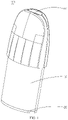
FIG. 1 is a schematic diagram of the atomizer of the present disclosure; -
FIG. 2 is an exploded view of the atomizer of the present disclosure; -
FIG. 3 is a schematic diagram of the base of the atomizer shown inFIG. 1 ; -
FIG. 4 is a schematic diagram of the connecting member of the atomizer shown inFIG. 1 ; -
FIG. 5 is another schematic diagram of the connecting member shown inFIG. 3 ; -
FIG. 6 is a schematic diagram of the heating structure of the atomizer shown inFIG. 1 ; -
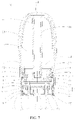
FIG. 7 is a cross-sectional view of the atomizer of the present disclosure; - The part names and reference signs shown in the figures are as follows:
atomizer 100liquid storage member 10base 20connecting member 30mounting member 40heating structure 50smoke outlet pipe 11air outlet 111liquid storage chamber 12first latching groove 13mounting protrusion 21air inlet 22mounting hole 23step surface 24 second collecting tank 25first latching tab 211second latching groove 212groove 213first sealing ring 60main body 31connecting protrusion 32first collecting tank 311through hole 33airflow passage 34 communication passage 35electrode 70second latching tab 41limiting ring 42smoke passage 43 liquid guiding member 51heating member 52communication hole 511accommodating groove 512sealing member 80second sealing ring 90fixing hole 811liquid inlet 82mounting groove 83 smoke outlet passage 14abutting portion214 base body26 air intake pipe 261abutting protrusion 262 - The present disclosure will now be described in detail with reference to the accompanying drawings. These figures are simplified schematic diagrams, which only illustrate the basic structure of the present disclosure in a schematic manner, so they only show the structures related to the present disclosure.
- As shown in
FIG. 1 andFIG. 7 , the present disclosure provides an aerosol generating device. The aerosol generating device includes anatomizer 100 and a power supply device electrically connected to theatomizer 100. Specifically, theatomizer 100 includes aliquid storage member 10, abase 20 disposed at one end of theliquid storage member 10, a connectingmember 30 disposed on thebase 20, amounting member 40 received in theliquid storage member 10, and aheating structure 50 mounted to themounting member 40. In use, the aerosol-forming substrate in theliquid storage member 10 enters into theheating structure 50, the power supply device supplies power to theheating structure 50, and theheating structure 50 atomizes the aerosol-forming substrate to generate smoke for the user to inhale. - The
liquid storage member 10 is substantially cylindrical with an opening at one end thereof. Theliquid storage member 10 is provided with asmoke outlet pipe 11 therein, thesmoke outlet pipe 11 has a hollow cylindrical structure with openings at opposite ends, the upper end of thesmoke outlet pipe 11 penetrates through theliquid storage member 10 and is opened to form anair outlet 111. The space between the inner wall of theliquid storage member 10 and the outer wall of thesmoke outlet pipe 11 forms aliquid storage chamber 12 for storing the aerosol-forming substrate, the inner cavity of thesmoke outlet pipe 11 forms asmoke outlet passage 14. The inner walls at opposite sides of theliquid storage member 10 are provided withfirst latching grooves 13. - As shown in
FIG. 2 ,FIG. 3 andFIG.7 , thebase 20 includes a base body 26 and amounting protrusion 21, themounting protrusion 21 is protruded from the base body 26, themounting protrusion 21 has a hollow cylindrical structure, and the base body 26 is protruded with anair intake pipe 261 and two abuttingprotrusions 262. In this embodiment, theair intake pipe 261 is approximately provided at the center of the base body 26, the two abuttingprotrusions 262 are located at opposite sides of theair intake pipe 261, theair intake pipe 261 is provided with anair inlet 22 extending through the base body 26, eachabutting protrusion 262 is provided with amounting hole 23 extending through the base body 26. The outer wall of theair intake pipe 261, the outer walls of the abuttingprotrusions 262, the inner wall of themounting protrusion 21 and the upper end surface of the base body 26 are jointly enclosed to form asecond collecting tank 25. There is a preset height difference between the bottom groove wall of thesecond collecting tank 25 and the upper end surface of theair intake pipe 261. In addition, a step surface 24 is formed between the outer peripheral wall of themounting protrusion 21 and the outer peripheral wall of thebase 20. -
First latching tabs 211 andsecond latching grooves 212 are provided at the opposite side walls of themounting protrusion 21. Thefirst latching tabs 211 are corresponding to thefirst latching grooves 13. Anannular groove 213 is concavely formed on the outer peripheral wall of themounting protrusion 21. When thebase 20 is installed at one end of theliquid storage member 10, themounting protrusion 21 is inserted into theliquid storage member 10, the bottom wall of theliquid storage member 10 abuts against the step surface 24, thefirst latching tab 211 is engaged in thefirst latching groove 13 to enhance the connection strength. Themounting protrusion 21 is also provided with anabutting portion 214. Theatomizer 100 further includes afirst sealing ring 60, thefirst sealing ring 60 is received in thegroove 213 and sandwiched between theliquid storage member 10 and thebase 20 to enhance sealing performance. It can be understood that, thefirst sealing ring 60 is made of a sealing material such as rubber or silicone. - As shown in
FIG. 4 ,FIG. 5 andFIG. 7 , the connectingmember 30 is disposed between thebase 20 and thesmoke outlet pipe 11. The connectingmember 30 includes amain body 31 and two connectingprotrusions 32. The connectingprotrusion 32 is protruded from themain body 31. One end of themain body 31 adjacent to thesmoke outlet pipe 11 is recessed to form afirst collecting tank 311. Thefirst collecting tank 311 is corresponding to thesmoke outlet passage 14, that is, thefirst collecting tank 311 is located under thesmoke outlet passage 14. Each connectingprotrusion 32 is provided with athrough hole 33, the throughhole 33 penetrates through themain body 31 and the connectingprotrusion 32. Each connectingprotrusion 32 corresponds to one of theabutting protrusions 262. The connectingmember 30 is received in the cavity of themounting protrusion 21, each connectingprotrusion 32 abuts against a correspondingabutting protrusion 262. An airflow passage 34 is formed between the lower end surface of themain body 31 and the upper end surface of the base body 26. Acommunication passage 35 is formed between the outer peripheral wall of the connectingmember 30 and the inner wall of themounting protrusion 21. One end of the airflow passage 34 is communicated with theair inlet 22. The other end of the airflow passage 34 is communicated with thecommunication passage 35. - The
atomizer 100 further includes twoelectrodes 70, each of theelectrodes 70 corresponds to one of the mounting holes 23. One end of eachelectrode 70 is received in the corresponding mountinghole 23, the other end of theelectrode 70 passes through the mountinghole 23 and the throughhole 33 in sequence and is received in the inner cavity of the mountingprotrusion 21. The upper end surface of theelectrode 70 is higher than the upper end surface of the connectingmember 30. One of theelectrodes 70 is electrically connected to one of the positive and negative electrodes of the power supply device, theother electrode 70 is electrically connected to the other one of the positive and negative electrodes of the power supply device. - The mounting
member 40 is generally in the shape of a hollow cylinder with two ends open. The inner cavity of the mountingmember 40 is communicated with theliquid storage chamber 12. Second latchingtabs 41 and a limitingring 42 are protruded from the outer peripheral wall of the two opposite sides of the mountingmember 40. One end of the mountingmember 40 is inserted into the mountingprotrusion 21 and abuts against the abuttingportion 214. Thesecond latching tab 41 is clamped in thesecond latching groove 212. The limitingring 42 abuts against the upper end surface of the mountingprotrusion 21. A smoke passage 43 communicated with thecommunication passage 35 is formed between the lower end surface of the mountingmember 40 and the upper end surface of the connectingmember 30. One end of the smoke passage 43 is communicated with thecommunication passage 35, the other end of the smoke passage 43 is communicated with thesmoke outlet passage 14. In this embodiment, a gap is provided between the lower end surface of the mountingmember 40 and the upper end surface of the connectingmember 30 to form the smoke passage 43. It can be understood that, in other embodiments not shown, the smoke passage 43 can also be provided at the upper end surface of the connectingmember 30. - As shown in
FIG. 6 andFIG. 7 , theheating structure 50 includes aliquid guiding member 51 and aheating member 52 which are in contact with each other. Theliquid guiding member 51 is provided with acommunication hole 511. One end surface of theliquid guiding member 51 is recessed to form an annularaccommodating groove 512. In this embodiment, thecommunication hole 511 is provided approximately at the center of theliquid guiding member 51. Theaccommodating groove 512 is arranged around thecommunication hole 511. Theliquid guiding member 51 is a porous ceramic. Theliquid guiding member 51 is provided with a plurality of capillary holes, so that theliquid guiding member 51 can absorb and store the aerosol-forming substrate. Theheating member 52 is arranged on the bottom of theliquid guiding member 51. That is, theheating member 52 is arranged at one end of theliquid guiding member 51 adjacent to theelectrodes 70. Theheating member 52 is a heating wire sintered on theliquid guiding member 51. Theliquid guiding member 51 is received in the mountingmember 40, and theliquid guiding member 51 is sleeved on the outside of thesmoke outlet pipe 11. Thecommunication hole 511 is communicated with thesmoke outlet passage 14. One end of theliquid guiding member 51 where theheating member 52 is installed is abutted against theelectrodes 70, and theheating member 52 is provided with two pins, one of the pins is electrically connected to one of theelectrodes 70, and the other pin is electrically connected to theother electrode 70, so that theheating member 52 is electrically connected to the power supply device. When the user uses the aerosol generating device, the aerosol-forming substrate in theliquid storage chamber 12 flows through the upper end of the mountingmember 40 to theaccommodating grooves 512 of theliquid guiding member 51; under the electric driving action of the power supply device, theheating member 52 generates heat, and heats the aerosol-forming substrate stored at theliquid guiding member 51. The aerosol-forming substrate is atomized to generate smoke that is emitted into the smoke passage 43. The arrangement of theaccommodating grooves 512 increases the contact area between the liquid guidingmember 51 and the aerosol-forming substrate, and improves the liquid guiding capability of theliquid guiding member 51. - In one embodiment, in order to further enhance the sealing between the mounting
member 40 and theheating structure 50 and between the mountingmember 40 and theliquid storage member 10, and prevent liquid leakage, theatomizer 100 further includes a sealingmember 80 and asecond sealing ring 90. The sealingmember 80 is protruded with a fixingprotrusion 81. The fixingprotrusion 81 is provided with a fixinghole 811. The sealingmember 80 is provided with twoliquid inlets 82 which are located at the opposite sides of the fixingprotrusion 81, respectively. In this embodiment, the fixingprotrusion 81 is arranged approximately at the center of the sealingmember 80. The lower end surface of the sealingmember 80 is recessed upward along the axial direction to form a mounting groove 83 which is communicated with theliquid inlet 82. The sealingmember 80 is received in the mountingmember 40, and the sealingmember 80 is sandwiched between theheating structure 50 and the mountingmember 40. The fixinghole 811 is communicated with thecommunication hole 511. Thesecond sealing ring 90 is sandwiched between the mountingmember 40 and theliquid storage member 10. - When the
atomizer 100 is in use, the aerosol-forming substrate in theliquid storage chamber 11 flows to theliquid guiding member 51 through theliquid inlets 82. When the user activates the aerosol generating device, theheating member 52 generates heat under the electric driving of the power supply device, and heats the aerosol-forming substrate stored in theliquid guiding member 51, so that the aerosol-forming substrate is atomized to generate smoke that is emitted to the smoke passage 43. The outside air enters the airflow passage 34 through theair inlet 22, then flows through thecommunication passage 35 and the smoke passage 43 in turn, and carries the smoke to flow through thesmoke outlet passage 14 and theair outlet 111 so as to enter the user's mouth. During the use of theatomizer 100, the condensate in thesmoke outlet pipe 11, the leaked aerosol-forming substrate and the aerosol-forming substrate that is not atomized timely by theheating structure 50 can be collected by thefirst collecting tank 311. The condensate in thecommunication passage 35 and the condensate on the inner wall of the mountingprotrusion 21 and the bottom wall of the connectingmember 30 can be collected by thesecond collecting tank 25. In addition, when the condensate in thefirst collecting tank 311 is full, the condensate overflowing from thefirst collecting tank 311 can flow into thesecond collecting tank 25 through thecommunication passage 35 so as to prevent the condensate in thefirst collecting tank 311 from flowing to the outside of the aerosol generating device. It can be understood that when the user tilts the atomizer, the condensate collected in thefirst collecting tank 311 can also flow into thesecond collecting tank 25 through thecommunication passage 35. In this way, it can also be avoided that the collection effect of thefirst collecting tank 311 is affected by too much condensate in thefirst collecting tank 311. - It can be understood that in other embodiments not shown, the
communication passage 35 can also be provided in the connectingmember 30. It only needs to satisfy that theheating structure 50 is arranged between thecommunication passage 35 and thesmoke outlet passage 14, and the air after passing through thecommunication passage 35 flows through theheating structure 50 to thesmoke outlet passage 14, and thecommunication passage 35 is staggered from theair inlet 22. - In the
atomizer 100 provided by the present disclosure, the connectingmember 30 is provided between the base 20 and thesmoke outlet pipe 11. The connectingmember 30 is provided with thefirst collecting tank 311 corresponding to thesmoke outlet pipe 11, so that the condensate generated in thesmoke outlet pipe 11 or the aerosol-forming substrate leaked in theatomizer 100 is collected in thefirst collecting tank 311, to avoid that the aerosol-forming substrate leaks from theair intake pipe 261 to the outside of the aerosol generating device, so as to prevent liquid leakage. Further, thesecond collecting tank 25 is provided in thebase 20, thecommunication passage 35 staggered from theair inlet 22 is provided between the connectingmember 30 and thebase 20, and thecommunication passage 35 is communicated with thesmoke outlet passage 14, so that the aerosol-forming substrate overflowing from thefirst collecting tank 311 can flow into thesecond collecting tank 25 through thecommunication passage 35, thereby further preventing liquid leakage. - The aerosol generating device provided by the present disclosure has the same technical effects as the above-mentioned
atomizer 100 because it has all the technical features of the above-mentionedatomizer 100. - Taking the above-mentioned ideal embodiments according to the present disclosure as enlightenment, through the above description, the relevant persons can make various changes and modifications without departing from the concept of the present disclosure. The technical scope of the present disclosure is not limited to the content of the specification, and its technical scope should be determined according to the scope of the claims.
Claims (10)
- An atomizer comprising a liquid storage member and a base disposed at one end of the liquid storage member, wherein a smoke outlet pipe is provided in the liquid storage member, the atomizer further comprises a connecting member disposed between the base and the smoke outlet pipe, an air intake pipe is protruded on the base, one end of the connecting member adjacent to the smoke outlet pipe is recessed to form a first collecting tank.
- The atomizer according to claim 1, wherein an end surface of the base facing the connecting member is provided with a second collecting tank, a gap is provided between an outer peripheral wall of the connecting member and the base, and the gap forms a communication passage, the air intake pipe is provided with an air inlet, the communication passage is staggered from the air inlet; the air inlet, the communication passage and an inner cavity of the smoke outlet pipe are communicated in sequence.
- The atomizer according to claim 1, wherein an end surface of the base facing the connecting member is provided with a second collecting tank, the connecting member is provided with a communication passage, the air intake pipe is provided with an air inlet, the communication passage is staggered from the air inlet; the air inlet, the communication passage and an inner cavity of the smoke outlet pipe are communicated in sequence.
- The atomizer according to claim 2 or 3, wherein the connecting member comprises a main body and two connecting protrusions, each connecting protrusion is protruded on the main body, the two connecting protrusions abut against the base, a lower end surface of the main body and an upper end surface of the base are enclosed to form an airflow passage, one end of the airflow passage is communicated with the air inlet, the other end of the airflow passage is communicated with the communication passage.
- The atomizer according to claim 4, wherein the base comprises a base body and a mounting protrusion, the mounting protrusion is protruded on the base body, the mounting protrusion has a hollow cylindrical structure, the connecting member is received in the cavity of the mounting protrusion, the communication passage is enclosed by an outer peripheral wall of the connecting member and an inner wall of the mounting protrusion.
- The atomizer according to claim 5, wherein two abutting protrusions are protruded on the base body, the air intake pipe is protruded on the base body, the two abutting protrusions are located at two opposite sides of the air intake pipe; the second collecting tank is enclosed by an outer wall of the air intake pipe, an outer wall of the abutting protrusion, the inner wall of the mounting protrusion and an upper end surface of the base body.
- The atomizer according to claim 6, wherein the abutting protrusion is provided with a mounting hole penetrating through the base body, the connecting protrusion is provided with two through holes, each of the abutting protrusions corresponds to one of the connecting protrusions, each of the connecting protrusions abuts against a corresponding abutting protrusion; the atomizer further comprises two electrodes, each of the electrodes corresponds to one of the mounting holes, one end of each of the electrodes is received in a corresponding mounting hole, the other end of each of the electrodes passes through the mounting hole and the through hole in sequence and is received in the cavity of the mounting protrusion; an upper end surface of the electrode is higher than an upper end surface of the connecting member.
- The atomizer according to claim 7, wherein the atomizer further comprises a mounting member and a heating structure received in the mounting member, a liquid storage chamber is provided in the liquid storage member, the mounting member is received in one end of the mounting protrusion away from the base body, one end of the mounting member away from the base is connected with the smoke outlet pipe and communicated with the liquid storage chamber, one end of the heating structure abuts against the electrode.
- The atomizer according to claim 8, wherein the heating structure comprises a liquid guiding member and a heating member which are in contact with each other, the heating member is arranged at one end of the liquid guiding member adjacent to the electrodes, the heating member is provided with two pins, one of the pins is electrically connected to one of the electrodes, the other pin is electrically connected to the other electrode.
- An aerosol generating device comprising the atomizer according to any one of claims 1 to 9.
Applications Claiming Priority (3)
| Application Number | Priority Date | Filing Date | Title |
|---|---|---|---|
| CN202020159567.4U CN211746937U (en) | 2020-02-10 | 2020-02-10 | Atomizer and its aerosol generating device |
| CN202021425565.1U CN212911688U (en) | 2020-02-10 | 2020-02-10 | Atomizer and its aerosol generating device |
| PCT/CN2021/071993 WO2021159915A1 (en) | 2020-02-10 | 2021-01-15 | Atomizer and aerosol generation apparatus with same |
Publications (2)
| Publication Number | Publication Date |
|---|---|
| EP4104690A1 true EP4104690A1 (en) | 2022-12-21 |
| EP4104690A4 EP4104690A4 (en) | 2024-03-13 |
Family
ID=72904211
Family Applications (1)
| Application Number | Title | Priority Date | Filing Date |
|---|---|---|---|
| EP21753445.2A Withdrawn EP4104690A4 (en) | 2020-02-10 | 2021-01-15 | ATOMIZER AND AEROSOL GENERATION DEVICE INCLUDING SAME |
Country Status (3)
| Country | Link |
|---|---|
| EP (1) | EP4104690A4 (en) |
| CN (2) | CN212911688U (en) |
| WO (1) | WO2021159915A1 (en) |
Families Citing this family (9)
| Publication number | Priority date | Publication date | Assignee | Title |
|---|---|---|---|---|
| CN212911688U (en) * | 2020-02-10 | 2021-04-09 | 常州市派腾电子技术服务有限公司 | Atomizer and its aerosol generating device |
| CN114847520B (en) * | 2021-01-20 | 2026-05-05 | 深圳市合元科技有限公司 | Atomizers and electronic atomization devices |
| WO2022183681A1 (en) * | 2021-03-05 | 2022-09-09 | 深圳雪雾科技有限公司 | Atomizer for electronic cigarette and electronic cigarette |
| CN215958369U (en) * | 2021-05-20 | 2022-03-08 | 深圳市合元科技有限公司 | Atomizer and aerosol-generating device |
| WO2023070975A1 (en) * | 2021-10-29 | 2023-05-04 | 深圳市卓力能技术有限公司 | Atomizer and electronic atomization device |
| CN114794572B (en) * | 2021-12-02 | 2025-03-21 | 深圳麦克韦尔科技有限公司 | Heating element assembly, atomizer and electronic atomization device |
| CN114209098B (en) * | 2021-12-21 | 2025-07-08 | 深圳市吉迩科技有限公司 | Anti-leakage atomization core, atomizer and aerosol generating device |
| CN114259084A (en) * | 2022-01-17 | 2022-04-01 | 海南摩尔兄弟科技有限公司 | Electronic atomization device and atomizer thereof |
| CN116687073A (en) * | 2023-06-19 | 2023-09-05 | 常州市派腾电子技术服务有限公司 | Atomizing core, atomizer and aerosol generating device |
Family Cites Families (12)
| Publication number | Priority date | Publication date | Assignee | Title |
|---|---|---|---|---|
| US9345269B2 (en) * | 2013-11-19 | 2016-05-24 | Tuanfang Liu | Electronic cigarette |
| CN204796750U (en) * | 2015-06-19 | 2015-11-25 | 卓尔悦(常州)电子科技有限公司 | Atomizer and aerosol generating device thereof |
| CN204907937U (en) * | 2015-08-26 | 2015-12-30 | 卓尔悦(常州)电子科技有限公司 | Atomizer and aerosol generating device thereof |
| CN206119187U (en) * | 2016-11-02 | 2017-04-26 | 常州市派腾电子技术服务有限公司 | Nebulizer and electronic cigarette with same |
| CN106690425B (en) * | 2017-02-28 | 2019-09-20 | 深圳市康泓威科技有限公司 | Anti-fog electronic cigarette |
| CN207613191U (en) * | 2017-06-23 | 2018-07-17 | 深圳市合元科技有限公司 | Leakproof oil fogger and electronic cigarette |
| CN208048026U (en) * | 2018-01-24 | 2018-11-06 | 深圳麦克韦尔股份有限公司 | Electronic cigarette and its atomizer |
| CN108158044B (en) * | 2018-03-12 | 2023-10-10 | 惠州市新泓威科技有限公司 | Electronic cigarette with dual chamber dual airway atomizer |
| CN209346085U (en) * | 2018-05-04 | 2019-09-06 | 深圳麦克韦尔科技有限公司 | Electronic cigarette and its atomising device |
| CN209518264U (en) * | 2018-12-28 | 2019-10-22 | 常州市派腾电子技术服务有限公司 | Atomizer and electronic cigarette |
| CN110236233A (en) * | 2019-06-28 | 2019-09-17 | 杨爽 | Electronic atomization device |
| CN212911688U (en) * | 2020-02-10 | 2021-04-09 | 常州市派腾电子技术服务有限公司 | Atomizer and its aerosol generating device |
-
2020
- 2020-02-10 CN CN202021425565.1U patent/CN212911688U/en not_active Expired - Fee Related
- 2020-02-10 CN CN202020159567.4U patent/CN211746937U/en not_active Expired - Fee Related
-
2021
- 2021-01-15 WO PCT/CN2021/071993 patent/WO2021159915A1/en not_active Ceased
- 2021-01-15 EP EP21753445.2A patent/EP4104690A4/en not_active Withdrawn
Also Published As
| Publication number | Publication date |
|---|---|
| CN211746937U (en) | 2020-10-27 |
| WO2021159915A1 (en) | 2021-08-19 |
| EP4104690A4 (en) | 2024-03-13 |
| CN212911688U (en) | 2021-04-09 |
Similar Documents
| Publication | Publication Date | Title |
|---|---|---|
| EP4118983A1 (en) | Atomizer and aerosol generating device thereof | |
| CN221489081U (en) | Electronic atomization device and atomizer thereof | |
| CN110250576B (en) | Electronic atomization device and atomizer thereof | |
| CN210275886U (en) | Atomizing components, atomizers and aerosol generating devices | |
| CN212164888U (en) | Atomizer and its aerosol generating device | |
| CN211746950U (en) | Atomizer and its aerosol generating device | |
| WO2021159915A1 (en) | Atomizer and aerosol generation apparatus with same | |
| US12262750B2 (en) | Atomizer and aerosol generating device with same | |
| US20230413906A1 (en) | Atomizer and aerosol generating device with same | |
| EP4133951A1 (en) | Atomizer and aerosol generation device | |
| CN215075476U (en) | Electronic atomization device and atomizer and atomization assembly thereof | |
| CN210275917U (en) | Atomization assembly, atomizer and aerosol generating device | |
| WO2023045586A1 (en) | Atomizer and aerosol-generating device | |
| CN218650266U (en) | Atomizer and electronic atomization device | |
| CN219719755U (en) | Atomizer and electronic atomization device | |
| WO2023116037A1 (en) | Anti-leakage atomization core, atomizer, and aerosol generation device | |
| WO2023039777A1 (en) | Atomizer and atomization apparatus | |
| CN220360088U (en) | Atomizer and aerosol generating device | |
| CN221449886U (en) | Atomizer and electronic atomization device | |
| CN220236041U (en) | Atomizer and electronic atomization device | |
| CN219593714U (en) | Electronic atomizing device and atomizer thereof | |
| CN115053993A (en) | Electronic atomization device and atomizer thereof | |
| CN224022896U (en) | Atomizer and atomizing device | |
| CN219422219U (en) | Atomizing device | |
| CN216568319U (en) | Electronic atomization device and its host |
Legal Events
| Date | Code | Title | Description |
|---|---|---|---|
| STAA | Information on the status of an ep patent application or granted ep patent |
Free format text: STATUS: THE INTERNATIONAL PUBLICATION HAS BEEN MADE |
|
| PUAI | Public reference made under article 153(3) epc to a published international application that has entered the european phase |
Free format text: ORIGINAL CODE: 0009012 |
|
| STAA | Information on the status of an ep patent application or granted ep patent |
Free format text: STATUS: REQUEST FOR EXAMINATION WAS MADE |
|
| 17P | Request for examination filed |
Effective date: 20220811 |
|
| AK | Designated contracting states |
Kind code of ref document: A1 Designated state(s): AL AT BE BG CH CY CZ DE DK EE ES FI FR GB GR HR HU IE IS IT LI LT LU LV MC MK MT NL NO PL PT RO RS SE SI SK SM TR |
|
| DAV | Request for validation of the european patent (deleted) | ||
| DAX | Request for extension of the european patent (deleted) | ||
| A4 | Supplementary search report drawn up and despatched |
Effective date: 20240214 |
|
| RIC1 | Information provided on ipc code assigned before grant |
Ipc: A24F 40/40 20200101ALI20240208BHEP Ipc: A24F 40/46 20200101ALI20240208BHEP Ipc: A24F 40/10 20200101AFI20240208BHEP |
|
| STAA | Information on the status of an ep patent application or granted ep patent |
Free format text: STATUS: THE APPLICATION IS DEEMED TO BE WITHDRAWN |
|
| 18D | Application deemed to be withdrawn |
Effective date: 20250801 |