EP4103100B1 - Vorrichtungen und systeme zum markieren von gewebe - Google Patents
Vorrichtungen und systeme zum markieren von gewebe Download PDFInfo
- Publication number
- EP4103100B1 EP4103100B1 EP21705073.1A EP21705073A EP4103100B1 EP 4103100 B1 EP4103100 B1 EP 4103100B1 EP 21705073 A EP21705073 A EP 21705073A EP 4103100 B1 EP4103100 B1 EP 4103100B1
- Authority
- EP
- European Patent Office
- Prior art keywords
- tissue marking
- beacon
- tissue
- led
- light
- Prior art date
- Legal status (The legal status is an assumption and is not a legal conclusion. Google has not performed a legal analysis and makes no representation as to the accuracy of the status listed.)
- Active
Links
Images


Classifications
-
- A—HUMAN NECESSITIES
- A61—MEDICAL OR VETERINARY SCIENCE; HYGIENE
- A61B—DIAGNOSIS; SURGERY; IDENTIFICATION
- A61B90/00—Instruments, implements or accessories specially adapted for surgery or diagnosis and not covered by any of the groups A61B1/00 - A61B50/00, e.g. for luxation treatment or for protecting wound edges
- A61B90/39—Markers, e.g. radio-opaque or breast lesions markers
-
- H—ELECTRICITY
- H02—GENERATION; CONVERSION OR DISTRIBUTION OF ELECTRIC POWER
- H02J—ELECTRIC POWER NETWORKS; CIRCUIT ARRANGEMENTS OR SYSTEMS FOR SUPPLYING OR DISTRIBUTING ELECTRIC POWER; SYSTEMS FOR STORING ELECTRIC ENERGY
- H02J50/00—Circuit arrangements or systems for wireless supply or distribution of electric power
- H02J50/10—Circuit arrangements or systems for wireless supply or distribution of electric power using inductive coupling
-
- H—ELECTRICITY
- H02—GENERATION; CONVERSION OR DISTRIBUTION OF ELECTRIC POWER
- H02J—ELECTRIC POWER NETWORKS; CIRCUIT ARRANGEMENTS OR SYSTEMS FOR SUPPLYING OR DISTRIBUTING ELECTRIC POWER; SYSTEMS FOR STORING ELECTRIC ENERGY
- H02J50/00—Circuit arrangements or systems for wireless supply or distribution of electric power
- H02J50/20—Circuit arrangements or systems for wireless supply or distribution of electric power using microwaves or radio frequency waves
-
- A—HUMAN NECESSITIES
- A61—MEDICAL OR VETERINARY SCIENCE; HYGIENE
- A61B—DIAGNOSIS; SURGERY; IDENTIFICATION
- A61B17/00—Surgical instruments, devices or methods
- A61B2017/00017—Electrical control of surgical instruments
- A61B2017/00221—Electrical control of surgical instruments with wireless transmission of data, e.g. by infrared radiation or radiowaves
-
- A—HUMAN NECESSITIES
- A61—MEDICAL OR VETERINARY SCIENCE; HYGIENE
- A61B—DIAGNOSIS; SURGERY; IDENTIFICATION
- A61B17/00—Surgical instruments, devices or methods
- A61B2017/00367—Details of actuation of instruments, e.g. relations between pushing buttons, or the like, and activation of the tool, working tip, or the like
- A61B2017/00411—Details of actuation of instruments, e.g. relations between pushing buttons, or the like, and activation of the tool, working tip, or the like actuated by application of energy from an energy source outside the body
-
- A—HUMAN NECESSITIES
- A61—MEDICAL OR VETERINARY SCIENCE; HYGIENE
- A61B—DIAGNOSIS; SURGERY; IDENTIFICATION
- A61B17/00—Surgical instruments, devices or methods
- A61B2017/00743—Type of operation; Specification of treatment sites
- A61B2017/00809—Lung operations
-
- A—HUMAN NECESSITIES
- A61—MEDICAL OR VETERINARY SCIENCE; HYGIENE
- A61B—DIAGNOSIS; SURGERY; IDENTIFICATION
- A61B90/00—Instruments, implements or accessories specially adapted for surgery or diagnosis and not covered by any of the groups A61B1/00 - A61B50/00, e.g. for luxation treatment or for protecting wound edges
- A61B90/39—Markers, e.g. radio-opaque or breast lesions markers
- A61B2090/3904—Markers, e.g. radio-opaque or breast lesions markers specially adapted for marking specified tissue
- A61B2090/3908—Soft tissue, e.g. breast tissue
-
- A—HUMAN NECESSITIES
- A61—MEDICAL OR VETERINARY SCIENCE; HYGIENE
- A61B—DIAGNOSIS; SURGERY; IDENTIFICATION
- A61B90/00—Instruments, implements or accessories specially adapted for surgery or diagnosis and not covered by any of the groups A61B1/00 - A61B50/00, e.g. for luxation treatment or for protecting wound edges
- A61B90/39—Markers, e.g. radio-opaque or breast lesions markers
- A61B2090/397—Markers, e.g. radio-opaque or breast lesions markers electromagnetic other than visible, e.g. microwave
- A61B2090/3975—Markers, e.g. radio-opaque or breast lesions markers electromagnetic other than visible, e.g. microwave active
- A61B2090/3979—Markers, e.g. radio-opaque or breast lesions markers electromagnetic other than visible, e.g. microwave active infrared
-
- A—HUMAN NECESSITIES
- A61—MEDICAL OR VETERINARY SCIENCE; HYGIENE
- A61B—DIAGNOSIS; SURGERY; IDENTIFICATION
- A61B90/00—Instruments, implements or accessories specially adapted for surgery or diagnosis and not covered by any of the groups A61B1/00 - A61B50/00, e.g. for luxation treatment or for protecting wound edges
- A61B90/36—Image-producing devices or illumination devices not otherwise provided for
- A61B90/361—Image-producing devices, e.g. surgical cameras
Definitions
- the disclosure relates to devices and systems for marking tissue and, more particularly, to devices and systems for marking tumors.
- US 2017/252124 A1 describes markers, probes, and related systems and methods are provided for localizing locations within a patient's body, e.g., a lesion within a breast.
- the marker includes an energy converter e.g., one or more photodiodes, for transforming light energy striking the marker into electrical energy, a storage device coupled to the energy converter for storing the electrical energy, a threshold element that closes a switch when the electrical energy reaches a predetermined threshold to discharge the electrical energy and cause the antenna to transmit a radio frequency (RF) signal.
- RF radio frequency
- EP1455673 A2 describes a system for generating a excitation field for excitation of a leadless marker assembly.
- One aspect of the system comprises a source generator assembly having a power supply, an energy storage device, a switching network and a source coil interconnected and configured to deliver a magnetic excitation signal waveform.
- a tissue marking beacon includes a storage capacitor including an onboard power coil.
- the onboard power coil wirelessly receives energy from a radio frequency (RF) field generator and stores an electrical charge in the storage capacitor.
- RF radio frequency
- a light-emitting diode (LED) emits pulsatile near-infrared (NIR) light upon receiving a current from the storage capacitor.
- a circuit is arranged between the storage capacitor and the LED. The circuit controls a flow of the current from the storage capacitor to the LED.
- a RF antenna receives external RF pulses and signals emission of the pulsatile NIR light from the LED in response to the external RF pulses.
- the tissue marking beacon is configured to be implanted in a tumor.
- the tissue marking beacon is configured to be implanted using a syringe.
- the tissue marking beacon may be disposed in a titanium sleeve.
- the circuit further includes a step-up circuit configured to increase a voltage supplied to the LED.
- a logic circuit may control an emission pattern of the pulsatile NIR light.
- a NIR camera detects emission of the pulsatile NIR light to determine a location of the tissue marking beacon.
- An emission pattern of the pulsatile NIR light is configured to be synchronized with a data capture rate and/or detector exposure (shutter) of the NIR camera.
- a second LED emits pulsatile NIR light upon receiving a current from a second storage capacitor.
- the emission pattern of the pulsatile NIR light from the LED is different from a second emission pattern of the pulsatile NIR light emitted from the second LED.
- a comparison of the emission pattern and the second emission pattern identifies a location and a depth of the tissue marking beacon.
- a RF field generator is configured to emit RF energy.
- the RF field generator is connected with the NIR camera.
- the RF field generator is configured to emit pulsatile RF energy to synchronize the emission pattern of the pulsatile NIR light with the data capture rate and/or detector exposure (shutter) of the NIR camera.
- parallel and perpendicular are understood to include relative configurations that are substantially parallel and substantially perpendicular up to about + or - 10 degrees from true parallel and true perpendicular.
- “About” or 'approximately” or “substantially” as used herein may be inclusive of the stated value and means within an acceptable range of variation for the particular value as determined by one of ordinary skill in the art, considering tolerances (e.g., material, manufacturing, use, environmental, etc.) as well as the measurement in question and the error associated with measurement of the particular quantity (e.g., the limitations of the measurement system). For example, “about:” may mean within one or more standard variations, or within ⁇ 30%, 20%, 10%, 5% of the stated value.
- Tumor localization refers to methods of identifying the specific location of tumors in organs pre and perioperatively.
- surgeons have been exploring a variety of approaches for localization, including the use of radioactive seeds, magnetic markers, and RFID. No technologies have emerged to enable the surgeon to localize a marker while actively preforming surgery as current approaches for localization involve the use of a hand-held wand to target and range the seed or implant.
- a seed e.g., a fiducial or a beacon
- a light emitting diode LED
- an 850nm LED e.g., having a range of from about 840nm to about 860nm
- the devices and systems described herein may be employed for tumor localization as deep as 6cm (e.g., for lung cancer treatment).
- the LED may be configured to produce a pulsatile signal that is within the visible spectrum, and thus the LED may be identifiable intra-operatively using known white-light methods.
- FIG. 1 illustrates a tissue marking system 110 in accordance with this disclosure.
- the system 110 generally includes a control module 101 having a display 102 for visualizing a position of a tissue marking beacon 100 (e.g., with respect to a surgical target such as a tumor in a patient's lung 150), a camera 104, an RF field generator 103 configured to emit RF energy, and the tissue marking beacon 100 configured to be located by the system 110.
- the tissue marking beacon 100 may be injected into a tumor site pre-operatively or perioperatively and then used to identify the location of the tumor.
- the camera 104 is a near-infrared (NIR) camera that detects emission of pulsatile NIR light from the tissue marking beacon 100 to determine a location of the tissue marking beacon 100.
- An emission pattern of the pulsatile NIR light is synchronized with a data capture rate of the NIR camera 104.
- a shutter speed/frequency of the NIR camera 104 may be synchronized with the emission pattern of the pulsatile NIR light such that the NIR light is emitted precisely when the camera shutter is in an open position, thus allowing a minimal amount of electrical current to be used by the tissue marking beacon 100.
- the RF field generator 103 may be coupled with the NIR camera 104 to facilitate the synchronization between the data capture rate and/or detector exposure (shutter) of the NIR camera 104 and the emission pattern of NIR light.
- the RF field generator 103 is configured to emit pulsatile RF energy to control when NIR light is emitted from the tissue marking beacon 100. While tissue marking beacon 100 is illustrated in FIG. 1 , any of the tissue marking beacons described herein may be employed by the tissue marking system 110.
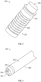
- FIG. 2 illustrates a tissue marking beacon 200 in accordance with aspects of this disclosure.
- the tissue marking beacon 200 includes a storage capacitor 201 including an onboard power coil 202.
- the storage capacitor 201 is an energy storage capacitor capable of high current discharge as a ratio of total energy stored.
- the onboard power coil 202 wirelessly receives energy from a radio frequency (RF) field generator (see, e.g., RF filed generator 103 of FIG. 1 ) and stores an electrical charge in the storage capacitor 201.
- RF radio frequency
- a light-emitting diode (LED) 204 emits pulsatile near-infrared (NIR) light upon receiving a current from the storage capacitor 201.
- a circuit see, e.g., circuit 601 of FIG.
- the circuit 6A is arranged between the storage capacitor 201 and the LED 204 and serves to control a flow of current from the storage capacitor 201 to the LED 204.
- the circuit may be configured to control a flow of current from the storage capacitor 201 to the LED 204 in a manner that alternates an emission of light from multiple LEDs.
- the circuit may be configured to discharge current to the LED 204 based on a signal passed through the power coil 202.
- the signal may be a cessation of transmitted power.
- An RF antenna 205 receives external RF pulses and signals emission of the pulsatile NIR light from the LED 204 in response to the external RF pulses.
- the RF pulses may be emitted from the RF filed generator 103.
- the RF field generator may be adjacent to a patient's body, or may be positioned on an instrument inside the patient's abdomen.
- Each of the tissue marking beacons described herein may be dimensioned to be implanted in a tumor by a syringe (e.g., a syringe having about a 16 gauge needle).
- the tissue marking beacon 200 is configured to be implanted in a tumor to mark a location of the tumor.
- the tissue marking beacons described herein can be implanted by Electromagnetic Navigation Bronchoscopy (ENB) or by an endoluminal robot.
- FIG. 3 illustrates a tissue marking beacon 300 in accordance with another aspect of this disclosure.
- the tissue marking beacon 300 is substantially the same as the other tissue marking beacons described herein, unless otherwise indicated.
- the tissue marking beacon 300 includes a storage capacitor 301, an onboard power coil 302, an LED 304, and an RF antenna 305.
- the tissue marking beacon 300 further includes a sleeve 308.
- the tissue marking beacon 300 may be disposed in the sleeve 308 for injection into a tumor.
- the sleeve 308 may include or may be formed of titanium. Titanium is a highly durable and cost-effective material for manufacturing. Using titanium or another similar relatively low-conductivity metal reduces eddy current losses induced from the RF field generator 103.
- the sleeve 308 may have a wall thickness of about 0.125mm, an outer diameter of 1.25mm, and a length of from about 12mm to about 15mm.
- FIGS. 4A, 4B, 4C and 4D illustrate a tissue marking beacon 400 in accordance with another aspect of this disclosure having at least two LEDs.
- tissue marking beacon 400 includes a first LED 404 and a second LED 414.
- An RF antenna 405 may signal NIR light emission from the first LED 404 and a corresponding RF antenna may signal NIR light emission from the second LED 414.
- the first LED 404 is positioned at a first end portion 412 of the tissue marking beacon 400 and the second LED 414 is positioned at a second end portion 422 of the tissue marking beacon 400 opposite the first end portion 412.
- the first LED 404 emits pulsatile NIR light upon receiving a current from a first storage capacitor 401.
- the second LED 414 emits pulsatile NIR light upon receiving a current from a second storage capacitor 411.
- a single storage capacitor may power each of the LEDs 404 and 414.
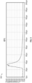
- FIG. 5 is a line graph 500 of an exemplary current discharge to an LED (e.g., LEDs 204, 404 or 414).
- the LED 204 may emit each pulse of NIR light for about 22ms.
- the current discharge illustrated in FIG. 5 may be similarly applicable to other LEDs described herein, unless otherwise indicated.
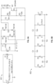
- FIG. 6A is a diagram of an exemplary circuit 601 for controlling the current discharge to LEDs 204, 404 or 414.
- the circuit 601 may further include a step-up circuit 602 (see, e.g., FIG. 6B ) configured to increase a voltage supplied to LEDs 204, 404 or 414.
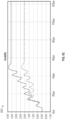
- FIG. 6C is a line graph 603 of an exemplary current step-up pattern of the step-up circuit 602.
- a logic circuit may control an emission pattern of the pulsatile NIR light emitted by LEDs 204, 404 or 414.
- the logic circuit may be onboard any of the tissue marking beacons described herein.
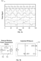
- FIG. 7A displays a graph 700 illustrating exemplary pulsatile emission patterns of NIR light. As an example, each pulse of NIR light may be emitted for about 22ms.
- FIG. 7B illustrates an external signaling device 703 employing exemplary circuit 704 and a receiver 701 employing exemplary circuit 702.
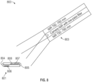
- FIG. 8 is a conceptual illustration of a solar photocell system 800 in accordance with an aspect of this disclosure including an external signaling device 803 a receiver 801 operating as a tissue marking beacon.
- the external signaling device 803 of the solar photocell system 800 may be on board the camera (e.g., camera 104), and thus the RF pulses from the RF field generator 104 need not be used.
- the camera may include a low-pass filter.
- the external signaling device 803 may emit light signals to the receiver 801 to trigger a desired emission of pulsatile NIR light from at least one of the LEDs 804 or 805 of the receiver 801.
- the camera 104 need not be coupled with the RF field generator 103 to synchronize the NIR emission pattern of the tissue marking beacon with the data capture rate of the camera 104.
- the camera 104 may directly regulate synchronization with the tissue marking beacon.
- the receiver 801 includes photovoltaic power cells 807 and 808 operated by a control/storage capacitor configured to control a flow of current to the LEDs 804, 805.
- the external signaling device 803 may transmit optical power at a first wavelength to the receiver 801.
- the receiver 801 may store electrical power (e.g., in photovoltaic power cells 807 and 808) and emit light of a second wavelength (e.g., different from the first wavelength) back to the external signaling device 803.
- a shutter of external signaling device 803 may be synchronized with the emitted light having the second wavelength.
- a signal may be transmitted in the optical power at the first wavelength to control the synchronization between the shutter of external signaling device 803 and the emitted light having the second wavelength.
- the external signaling device may emit light of the first wavelength in a range of from about 750nm to about 780nm and at least one of LEDs 804 or 805 may emit light of the second wavelength in a range of from about 830nm to about 850nm.
- a second LED/LD Laser Diode
- an LED/LD could be attached to both ends of the tissue marking beacon.
- the resulting two points of light can be triangulated to provide a location over distance.
- Two or more sources of light can also provide a relative orientation of the tissue marking beacon in free space.
- Each of the two LEDs may be pulsed with different identifiable emission patterns (e.g., different frequencies and/or with different emission timing).
- variations in color/wavelengths of light may be employed to differentiate opposite ends of the tissue marking beacon.
- Pulsing variations of each LED can provide discrimination based upon a (known) pulse repetition rate. Increased light intensity from the LED/LD can be achieved by pulsing the current through the diode(s).
- Pulsing of RF Energy to charge the RF beacon can be made synchronous to the detection camera such that the shutter and or exposure to charge the detector is synchronized with the RF pulse to the tissue marking beacon. This allows for increased discrimination of ambient light and increased signal detection accuracy.
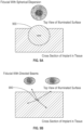
- FIGS. 9A and 9B illustrate dispersion patterns of a tissue marking beacon 900 in accordance with an aspect of this disclosure.
- Tissue marking beacon 900 is substantially the same as tissue marking beacon 400 described herein, unless otherwise indicated.
- the first emission pattern of the pulsatile NIR light from the first LED is different from a second emission pattern of the pulsatile NIR light emitted from the second LED.
- a comparison of the first emission pattern and the second emission pattern identifies a location and a depth of the tissue marking beacon 900.
- NIR light emitted from each LED may have a distinct spherical dispersion pattern.
- the relative intensity of the center intensity of light to the edge intensity of light allows a calculation of the depth of the tissue marking beacon 900 to be performed. This calculation may be performed because eccentricity of surface illuminations enables prediction of incident angles (see, e.g., Fig. 9B ) and triangulation to estimate a depth of the tissue marking beacon 900.
- the size and shape of a single dispersion pattern can be employed to predict a distance from a surface of the patient's skin to the tissue marking beacon 900.
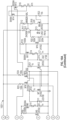
- FIG. 10A is a diagram of an exemplary circuit 1001 for controlling pulsatile emission patterns of two LEDs.
- FIG. 10B is a line graph 1002 of an exemplary current discharge pattern of two LEDs in accordance with the disclosure.
- FIG. 11 is a block diagram of an exemplary computer 1100 of the control module 101 of FIG. 1 .
- the computer of the control module 101 may include a processor 1101 connected to a computer-readable storage medium or a memory 1102 which may be a volatile type memory, e.g., RAM, or a non-volatile type memory, e.g., flash media, disk media, etc.
- the processor 1101 may be another type of processor such as, without limitation, a digital signal processor, a microprocessor, an ASIC, a graphics processing unit (GPU), field-programmable gate array (FPGA), or a central processing unit (CPU).
- GPU graphics processing unit
- FPGA field-programmable gate array
- CPU central processing unit
- the memory 1102 can be random access memory, read-only memory, magnetic disk memory, solid state memory, optical disc memory, and/or another type of memory.
- the memory 1102 can communicate with the processor 1101 through communication buses 1110 of a circuit board and/or through communication cables such as serial ATA cables or other types of cables.
- the memory 1102 includes computer-readable instructions that are executable by the processor 1101 to operate the control module.
- the control module 101 may include a network interface 1104 to communicate with other computers or a server.
- a storage device 1105 may be used for storing data.
- the control module 101 may include an AI or machine learning module 1106 (see, FIG. 1 ) including one or more FPGAs 1103.
- the FPGAs 1103 may be used for executing various machine learning algorithms such as those described herein (e.g., a location algorithm 1107 or a camera shutter/LED synchronization algorithm 1108).
- the storage device 1105 of the control module 101 store one or more machine learning algorithms and/or models, configured to determine a location, depth, and/or directional orientation of at least one tissue locating beacon, and to render an image on the display 102 of the tissue locating beacon with respect to a patient's anatomy.
- the machine learning algorithm may apply mathematical models to determine a location, depth, and/or directional orientation of at least one tissue locating beacon, and to render an image on the display 102 of the tissue locating beacon with respect to a patient's anatomy.
- the machine learning algorithm(s) may be trained on and learn from experimental data and/or data from previous procedures initially input into the one or more machine learning applications in order to enable the machine learning application(s) to determine a location, depth, and/or directional orientation of at least one tissue locating beacon, and to render an image on the display 102 of the tissue locating beacon with respect to a patient's anatomy.
- Machine learning algorithms are advantageous for use in determining a location, depth, and/or directional orientation of at least one tissue locating beacon, and to render an image on the display 102 of the tissue locating beacon with respect to a patient's anatomy, at least in that complex sensor components and pre-defined categorization rules and/or algorithms are not required. Rather, machine learning algorithms utilize initially input data to determine statistical features and/or correlations by analyzing data therefrom. Thus, with the one or more machine learning algorithms having been trained as detailed above, such can be used to determine a location, depth, and/or directional orientation of at least one tissue locating beacon, and to render an image on the display 102 of the tissue locating beacon with respect to a patient's anatomy.
- the various embodiments disclosed herein may also be configured to work with robotic surgical systems and what is commonly referred to as "Telesurgery.”
- Such systems employ various robotic elements to assist the surgeon and allow remote operation (or partial remote operation) of surgical instrumentation.
- Various robotic arms, gears, cams, pulleys, electric and mechanical motors, etc. may be employed for this purpose and may be designed with a robotic surgical system to assist the surgeon during the course of an operation or treatment.
- Such robotic systems may include remotely steerable systems, automatically flexible surgical systems, remotely flexible surgical systems, remotely articulating surgical systems, wireless surgical systems, modular or selectively configurable remotely operated surgical systems, etc.
- the robotic surgical systems may be employed with one or more consoles that are next to the operating theater or located in a remote location.
- one team of surgeons or nurses may prep the patient for surgery and configure the robotic surgical system with one or more of the instruments disclosed herein while another surgeon (or group of surgeons) remotely control the instruments via the robotic surgical system.
- a highly skilled surgeon may perform multiple operations in multiple locations without leaving his/her remote console which can be both economically advantageous and a benefit to the patient or a series of patients.
- the robotic arms of the surgical system are typically coupled to a pair of master handles by a controller.
- the handles can be moved by the surgeon to produce a corresponding movement of the working ends of any type of surgical instrument (e.g., end effectors, graspers, knifes, scissors, etc.) which may complement the use of one or more of the embodiments described herein.
- the movement of the master handles may be scaled so that the working ends have a corresponding movement that is different, smaller or larger, than the movement performed by the operating hands of the surgeon.
- the scale factor or gearing ratio may be adjustable so that the operator can control the resolution of the working ends of the surgical instrument(s).
- the master handles may include various sensors to provide feedback to the surgeon relating to various tissue parameters or conditions, e.g., tissue resistance due to manipulation, cutting or otherwise treating, pressure by the instrument onto the tissue, tissue temperature, tissue impedance, etc. As can be appreciated, such sensors provide the surgeon with enhanced tactile feedback simulating actual operating conditions.
- the master handles may also include a variety of different actuators for delicate tissue manipulation or treatment further enhancing the surgeon's ability to mimic actual operating conditions.
Landscapes
- Engineering & Computer Science (AREA)
- Health & Medical Sciences (AREA)
- Surgery (AREA)
- Life Sciences & Earth Sciences (AREA)
- Power Engineering (AREA)
- Computer Networks & Wireless Communication (AREA)
- Heart & Thoracic Surgery (AREA)
- Biomedical Technology (AREA)
- Pathology (AREA)
- Medical Informatics (AREA)
- Molecular Biology (AREA)
- Animal Behavior & Ethology (AREA)
- General Health & Medical Sciences (AREA)
- Public Health (AREA)
- Veterinary Medicine (AREA)
- Oral & Maxillofacial Surgery (AREA)
- Nuclear Medicine, Radiotherapy & Molecular Imaging (AREA)
- Surgical Instruments (AREA)
- Radiation-Therapy Devices (AREA)
Claims (6)
- Gewebemarkierungsleuchtfeuer (Beacon, 400), umfassend:einen Speicherkondensator (201, 401) mit einer integrierten Leistungsspule (202), wobei die integrierte Leistungsspule dazu ausgelegt ist, Energie von einem Funkfrequenz (RF)-Feldgenerator (103) drahtlos zu empfangen und eine elektrische Ladung in dem Speicherkondensator zu speichern;wobei das Gewebemarkierungsleuchtfeuer wenigstens eine erste Leuchtdiode (LED) (404) umfasst, die dazu ausgelegt ist, bei Empfang eines Stroms von dem Speicherkondensator pulsierendes Nah-Infrarot (NIR)-Licht zu emittieren; undeinen zweiten Speicherkondensator(411); undwenigstens eine zweite LED (414).
- Gewebemarkierungsleuchtfeuer (400) nach Anspruch 1, wobei das Gewebemarkierungsleuchtfeuer dazu ausgelegt ist, in einen Tumor implantiert zu werden.
- Gewebemarkierungsleuchtfeuer (400) nach Anspruch 2, wobei das Gewebemarkierungsleuchtfeuer dazu ausgelegt ist, unter Verwendung einer Spritze implantiert zu werden.
- Gewebemarkierungsleuchtfeuer (400) nach Anspruch 1, wobei das Gewebemarkierungsleuchtfeuer in einer Titanhülse (308) angeordnet ist.
- Gewebemarkierungsleuchtfeuer (400) nach Anspruch 1, wobei das Gewebemarkierungsleuchtfeuer in einer Glashülse angeordnet ist.
- Gewebemarkierungsleuchtfeuer (400) nach Anspruch 1, wobei das emittierte NIR-Licht von einer NIR-Kamera (104) beobachtet wird.
Applications Claiming Priority (2)
| Application Number | Priority Date | Filing Date | Title |
|---|---|---|---|
| US202062975310P | 2020-02-12 | 2020-02-12 | |
| PCT/US2021/014307 WO2021162838A1 (en) | 2020-02-12 | 2021-01-21 | Devices and systems for marking tissue |
Publications (2)
| Publication Number | Publication Date |
|---|---|
| EP4103100A1 EP4103100A1 (de) | 2022-12-21 |
| EP4103100B1 true EP4103100B1 (de) | 2025-05-07 |
Family
ID=74592825
Family Applications (1)
| Application Number | Title | Priority Date | Filing Date |
|---|---|---|---|
| EP21705073.1A Active EP4103100B1 (de) | 2020-02-12 | 2021-01-21 | Vorrichtungen und systeme zum markieren von gewebe |
Country Status (3)
| Country | Link |
|---|---|
| US (1) | US20230040646A1 (de) |
| EP (1) | EP4103100B1 (de) |
| WO (1) | WO2021162838A1 (de) |
Family Cites Families (9)
| Publication number | Priority date | Publication date | Assignee | Title |
|---|---|---|---|---|
| ATE397887T1 (de) * | 1998-04-07 | 2008-07-15 | Cytyc Corp | Vorrichtungen zur lokalisierung von läsionen in festem gewebe |
| US6812842B2 (en) * | 2001-12-20 | 2004-11-02 | Calypso Medical Technologies, Inc. | System for excitation of a leadless miniature marker |
| US20090036952A1 (en) * | 2007-07-30 | 2009-02-05 | National Yang-Ming University | Induction driven light module and use thereof |
| EP3232921B1 (de) * | 2014-12-16 | 2019-09-25 | Koninklijke Philips N.V. | Pulslichtemittierende markierungsvorrichtung |
| US20170095312A1 (en) * | 2015-10-02 | 2017-04-06 | Varian Medical Systems, Inc. | Markers including magnetic transponders with increased radiographic visibility |
| WO2017083412A1 (en) * | 2015-11-11 | 2017-05-18 | Devicor Medical Products, Inc. | Marker delivery device and method of deploying a marker |
| JP6929294B2 (ja) * | 2016-03-03 | 2021-09-01 | シアナ メディカル,インク. | 埋め込み可能なマーカ、それらを使用するための装置及び方法 |
| WO2018175667A1 (en) * | 2017-03-21 | 2018-09-27 | Cianna Medical, Inc. | Reflector markers and systems and methods for identifying and locating them |
| EP3725257A1 (de) * | 2019-04-16 | 2020-10-21 | Koninklijke Philips N.V. | Lichtbetriebener, lichtemittierender gewebemarker |
-
2021
- 2021-01-21 EP EP21705073.1A patent/EP4103100B1/de active Active
- 2021-01-21 US US17/792,503 patent/US20230040646A1/en active Pending
- 2021-01-21 WO PCT/US2021/014307 patent/WO2021162838A1/en not_active Ceased
Also Published As
| Publication number | Publication date |
|---|---|
| WO2021162838A1 (en) | 2021-08-19 |
| US20230040646A1 (en) | 2023-02-09 |
| EP4103100A1 (de) | 2022-12-21 |
Similar Documents
| Publication | Publication Date | Title |
|---|---|---|
| JP7826193B2 (ja) | 手術器具用トラッカ | |
| CN106606374B (zh) | 用于消融手术的计划系统和导航系统 | |
| CN103445866B (zh) | 外科规划系统和导航系统 | |
| EP3396810B1 (de) | Verwendung von positionsübertragungssignalen zum laden eines drahtlosen werkzeugs eines elektromagnetischen navigationssystems | |
| CN107550568B (zh) | 处理计划系统 | |
| US20250345146A1 (en) | Systems and methods for sensing presence of medical tools | |
| US20190298451A1 (en) | Systems and methods for delivering targeted therapy | |
| CN107997821B (zh) | 用于计划和导航的系统和方法 | |
| KR102776874B1 (ko) | 도구 검출 및 연관 제어 모드를 위한 시스템 및 방법 | |
| US20200315711A1 (en) | Systems, devices, and methods for providing surgical trajectory guidance | |
| JP2007260404A (ja) | 患者の運動学上の動作をモニターするためのシステムおよび方法 | |
| US20200188044A1 (en) | Guidance of Robotically Controlled Instruments Along Paths Defined with Reference to Auxiliary Instruments | |
| EP3366248B1 (de) | System und verfahren zur katheteridentifikation | |
| EP4103100B1 (de) | Vorrichtungen und systeme zum markieren von gewebe | |
| US20260013951A1 (en) | Systems and methods for wireless localization integration | |
| US20240099781A1 (en) | Neuromapping systems, methods, and devices | |
| WO2025160140A1 (en) | Marker reflector systems with light emitters | |
| WO2025212319A1 (en) | Computer-assisted annotation of subsurface structures onto a surface |
Legal Events
| Date | Code | Title | Description |
|---|---|---|---|
| STAA | Information on the status of an ep patent application or granted ep patent |
Free format text: STATUS: UNKNOWN |
|
| STAA | Information on the status of an ep patent application or granted ep patent |
Free format text: STATUS: THE INTERNATIONAL PUBLICATION HAS BEEN MADE |
|
| PUAI | Public reference made under article 153(3) epc to a published international application that has entered the european phase |
Free format text: ORIGINAL CODE: 0009012 |
|
| STAA | Information on the status of an ep patent application or granted ep patent |
Free format text: STATUS: REQUEST FOR EXAMINATION WAS MADE |
|
| 17P | Request for examination filed |
Effective date: 20220909 |
|
| AK | Designated contracting states |
Kind code of ref document: A1 Designated state(s): AL AT BE BG CH CY CZ DE DK EE ES FI FR GB GR HR HU IE IS IT LI LT LU LV MC MK MT NL NO PL PT RO RS SE SI SK SM TR |
|
| DAV | Request for validation of the european patent (deleted) | ||
| DAX | Request for extension of the european patent (deleted) | ||
| GRAP | Despatch of communication of intention to grant a patent |
Free format text: ORIGINAL CODE: EPIDOSNIGR1 |
|
| STAA | Information on the status of an ep patent application or granted ep patent |
Free format text: STATUS: GRANT OF PATENT IS INTENDED |
|
| INTG | Intention to grant announced |
Effective date: 20241212 |
|
| GRAS | Grant fee paid |
Free format text: ORIGINAL CODE: EPIDOSNIGR3 |
|
| GRAA | (expected) grant |
Free format text: ORIGINAL CODE: 0009210 |
|
| STAA | Information on the status of an ep patent application or granted ep patent |
Free format text: STATUS: THE PATENT HAS BEEN GRANTED |
|
| AK | Designated contracting states |
Kind code of ref document: B1 Designated state(s): AL AT BE BG CH CY CZ DE DK EE ES FI FR GB GR HR HU IE IS IT LI LT LU LV MC MK MT NL NO PL PT RO RS SE SI SK SM TR |
|
| REG | Reference to a national code |
Ref country code: GB Ref legal event code: FG4D |
|
| REG | Reference to a national code |
Ref country code: CH Ref legal event code: EP |
|
| REG | Reference to a national code |
Ref country code: DE Ref legal event code: R096 Ref document number: 602021030373 Country of ref document: DE |
|
| REG | Reference to a national code |
Ref country code: IE Ref legal event code: FG4D |
|
| REG | Reference to a national code |
Ref country code: NL Ref legal event code: MP Effective date: 20250507 |
|
| PG25 | Lapsed in a contracting state [announced via postgrant information from national office to epo] |
Ref country code: ES Free format text: LAPSE BECAUSE OF FAILURE TO SUBMIT A TRANSLATION OF THE DESCRIPTION OR TO PAY THE FEE WITHIN THE PRESCRIBED TIME-LIMIT Effective date: 20250507 Ref country code: PT Free format text: LAPSE BECAUSE OF FAILURE TO SUBMIT A TRANSLATION OF THE DESCRIPTION OR TO PAY THE FEE WITHIN THE PRESCRIBED TIME-LIMIT Effective date: 20250908 Ref country code: FI Free format text: LAPSE BECAUSE OF FAILURE TO SUBMIT A TRANSLATION OF THE DESCRIPTION OR TO PAY THE FEE WITHIN THE PRESCRIBED TIME-LIMIT Effective date: 20250507 |
|
| REG | Reference to a national code |
Ref country code: LT Ref legal event code: MG9D |
|
| PG25 | Lapsed in a contracting state [announced via postgrant information from national office to epo] |
Ref country code: NO Free format text: LAPSE BECAUSE OF FAILURE TO SUBMIT A TRANSLATION OF THE DESCRIPTION OR TO PAY THE FEE WITHIN THE PRESCRIBED TIME-LIMIT Effective date: 20250807 Ref country code: GR Free format text: LAPSE BECAUSE OF FAILURE TO SUBMIT A TRANSLATION OF THE DESCRIPTION OR TO PAY THE FEE WITHIN THE PRESCRIBED TIME-LIMIT Effective date: 20250808 |
|
| PG25 | Lapsed in a contracting state [announced via postgrant information from national office to epo] |
Ref country code: NL Free format text: LAPSE BECAUSE OF FAILURE TO SUBMIT A TRANSLATION OF THE DESCRIPTION OR TO PAY THE FEE WITHIN THE PRESCRIBED TIME-LIMIT Effective date: 20250507 Ref country code: PL Free format text: LAPSE BECAUSE OF FAILURE TO SUBMIT A TRANSLATION OF THE DESCRIPTION OR TO PAY THE FEE WITHIN THE PRESCRIBED TIME-LIMIT Effective date: 20250507 |
|
| REG | Reference to a national code |
Ref country code: AT Ref legal event code: MK05 Ref document number: 1791619 Country of ref document: AT Kind code of ref document: T Effective date: 20250507 |
|
| PG25 | Lapsed in a contracting state [announced via postgrant information from national office to epo] |
Ref country code: BG Free format text: LAPSE BECAUSE OF FAILURE TO SUBMIT A TRANSLATION OF THE DESCRIPTION OR TO PAY THE FEE WITHIN THE PRESCRIBED TIME-LIMIT Effective date: 20250507 |
|
| PG25 | Lapsed in a contracting state [announced via postgrant information from national office to epo] |
Ref country code: HR Free format text: LAPSE BECAUSE OF FAILURE TO SUBMIT A TRANSLATION OF THE DESCRIPTION OR TO PAY THE FEE WITHIN THE PRESCRIBED TIME-LIMIT Effective date: 20250507 |
|
| PG25 | Lapsed in a contracting state [announced via postgrant information from national office to epo] |
Ref country code: AT Free format text: LAPSE BECAUSE OF FAILURE TO SUBMIT A TRANSLATION OF THE DESCRIPTION OR TO PAY THE FEE WITHIN THE PRESCRIBED TIME-LIMIT Effective date: 20250507 |
|
| PG25 | Lapsed in a contracting state [announced via postgrant information from national office to epo] |
Ref country code: RS Free format text: LAPSE BECAUSE OF FAILURE TO SUBMIT A TRANSLATION OF THE DESCRIPTION OR TO PAY THE FEE WITHIN THE PRESCRIBED TIME-LIMIT Effective date: 20250807 |
|
| PG25 | Lapsed in a contracting state [announced via postgrant information from national office to epo] |
Ref country code: IS Free format text: LAPSE BECAUSE OF FAILURE TO SUBMIT A TRANSLATION OF THE DESCRIPTION OR TO PAY THE FEE WITHIN THE PRESCRIBED TIME-LIMIT Effective date: 20250907 |
|
| PG25 | Lapsed in a contracting state [announced via postgrant information from national office to epo] |
Ref country code: LV Free format text: LAPSE BECAUSE OF FAILURE TO SUBMIT A TRANSLATION OF THE DESCRIPTION OR TO PAY THE FEE WITHIN THE PRESCRIBED TIME-LIMIT Effective date: 20250507 |
|
| PGFP | Annual fee paid to national office [announced via postgrant information from national office to epo] |
Ref country code: GB Payment date: 20251220 Year of fee payment: 6 |
|
| PG25 | Lapsed in a contracting state [announced via postgrant information from national office to epo] |
Ref country code: DK Free format text: LAPSE BECAUSE OF FAILURE TO SUBMIT A TRANSLATION OF THE DESCRIPTION OR TO PAY THE FEE WITHIN THE PRESCRIBED TIME-LIMIT Effective date: 20250507 Ref country code: SM Free format text: LAPSE BECAUSE OF FAILURE TO SUBMIT A TRANSLATION OF THE DESCRIPTION OR TO PAY THE FEE WITHIN THE PRESCRIBED TIME-LIMIT Effective date: 20250507 |
|
| PGFP | Annual fee paid to national office [announced via postgrant information from national office to epo] |
Ref country code: FR Payment date: 20251218 Year of fee payment: 6 |
|
| PG25 | Lapsed in a contracting state [announced via postgrant information from national office to epo] |
Ref country code: CZ Free format text: LAPSE BECAUSE OF FAILURE TO SUBMIT A TRANSLATION OF THE DESCRIPTION OR TO PAY THE FEE WITHIN THE PRESCRIBED TIME-LIMIT Effective date: 20250507 |
|
| PGFP | Annual fee paid to national office [announced via postgrant information from national office to epo] |
Ref country code: IE Payment date: 20251218 Year of fee payment: 6 |
|
| PG25 | Lapsed in a contracting state [announced via postgrant information from national office to epo] |
Ref country code: EE Free format text: LAPSE BECAUSE OF FAILURE TO SUBMIT A TRANSLATION OF THE DESCRIPTION OR TO PAY THE FEE WITHIN THE PRESCRIBED TIME-LIMIT Effective date: 20250507 |
|
| PG25 | Lapsed in a contracting state [announced via postgrant information from national office to epo] |
Ref country code: SK Free format text: LAPSE BECAUSE OF FAILURE TO SUBMIT A TRANSLATION OF THE DESCRIPTION OR TO PAY THE FEE WITHIN THE PRESCRIBED TIME-LIMIT Effective date: 20250507 |
|
| PG25 | Lapsed in a contracting state [announced via postgrant information from national office to epo] |
Ref country code: IT Free format text: LAPSE BECAUSE OF FAILURE TO SUBMIT A TRANSLATION OF THE DESCRIPTION OR TO PAY THE FEE WITHIN THE PRESCRIBED TIME-LIMIT Effective date: 20250507 |
|
| REG | Reference to a national code |
Ref country code: DE Ref legal event code: R097 Ref document number: 602021030373 Country of ref document: DE |
|
| PLBE | No opposition filed within time limit |
Free format text: ORIGINAL CODE: 0009261 |
|
| STAA | Information on the status of an ep patent application or granted ep patent |
Free format text: STATUS: NO OPPOSITION FILED WITHIN TIME LIMIT |
|
| REG | Reference to a national code |
Ref country code: CH Ref legal event code: L10 Free format text: ST27 STATUS EVENT CODE: U-0-0-L10-L00 (AS PROVIDED BY THE NATIONAL OFFICE) Effective date: 20260318 |