EP4102754A1 - Transmission parameter determination method, terminal device, and network device - Google Patents
Transmission parameter determination method, terminal device, and network device Download PDFInfo
- Publication number
- EP4102754A1 EP4102754A1 EP20918563.6A EP20918563A EP4102754A1 EP 4102754 A1 EP4102754 A1 EP 4102754A1 EP 20918563 A EP20918563 A EP 20918563A EP 4102754 A1 EP4102754 A1 EP 4102754A1
- Authority
- EP
- European Patent Office
- Prior art keywords
- transmission parameter
- dci
- dci format
- configured grant
- indication field
- Prior art date
- Legal status (The legal status is an assumption and is not a legal conclusion. Google has not performed a legal analysis and makes no representation as to the accuracy of the status listed.)
- Pending
Links
Images

Classifications
-
- H—ELECTRICITY
- H04—ELECTRIC COMMUNICATION TECHNIQUE
- H04W—WIRELESS COMMUNICATION NETWORKS
- H04W72/00—Local resource management
- H04W72/20—Control channels or signalling for resource management
- H04W72/23—Control channels or signalling for resource management in the downlink direction of a wireless link, i.e. towards a terminal
-
- H—ELECTRICITY
- H04—ELECTRIC COMMUNICATION TECHNIQUE
- H04L—TRANSMISSION OF DIGITAL INFORMATION, e.g. TELEGRAPHIC COMMUNICATION
- H04L5/00—Arrangements affording multiple use of the transmission path
- H04L5/003—Arrangements for allocating sub-channels of the transmission path
- H04L5/0044—Allocation of payload; Allocation of data channels, e.g. PDSCH or PUSCH
- H04L5/0046—Determination of the number of bits transmitted on different sub-channels
-
- H—ELECTRICITY
- H04—ELECTRIC COMMUNICATION TECHNIQUE
- H04L—TRANSMISSION OF DIGITAL INFORMATION, e.g. TELEGRAPHIC COMMUNICATION
- H04L5/00—Arrangements affording multiple use of the transmission path
- H04L5/003—Arrangements for allocating sub-channels of the transmission path
- H04L5/0053—Allocation of signalling, i.e. of overhead other than pilot signals
-
- H—ELECTRICITY
- H04—ELECTRIC COMMUNICATION TECHNIQUE
- H04W—WIRELESS COMMUNICATION NETWORKS
- H04W72/00—Local resource management
- H04W72/04—Wireless resource allocation
- H04W72/115—Grant-free or autonomous transmission
Definitions
- the present disclosure relates to the field of communications, and in particular, to a transmission parameter determination method, a terminal device, a network device, a chip, a computer-readable storage medium, a computer program product, and a computer program.
- the order and the number of bits of each filed in the downlink control information (DCI) format are determined.
- DCI downlink control information
- CG configured grant
- the bits of each domain in the activation and retransmission DCI may be determined by different parameters.
- the number of bits in the same indication field will vary. Therefore, it is necessary to solve the problem of different number of bits of a certain indication field in the DCI corresponding to different transmission parameter set configurations.
- embodiments of the present disclosure provide a transmission parameter determination method, a terminal device, a network device, a chip, a computer-readable storage medium, a computer program product, and a computer program.
- a transmission parameter determination method including: The terminal device receives a first transmission parameter.
- the first transmission parameter is used to determine the number of bits of the first indication field in the DCI (downlink control information); a first transmission parameter set and a second transmission parameter set correspond to the first indication field in the DCI.
- a transmission parameter determination method including:
- the network device sends the first transmission parameter.
- the first transmission parameter is used to determine the number of bits of the first indication field in the DCI; the first transmission parameter and the second transmission parameter correspond to the first indication field in the DCI.
- a terminal device including: A first communication unit receives the first transmission parameter.
- the first transmission parameter is used to determine the number of bits of the first indication field in the DCI; the first transmission parameter set and the second transmission parameter set correspond to the first indication field in the DCI.
- a network device including: A second communication unit sends the first transmission parameter.
- the first transmission parameter is used to determine the number of bits of the first indication field in the DCI; the first transmission parameter and the second transmission parameter correspond to the first indication field in the DCI.
- a terminal device including: a processor and a memory for storing a computer program that can be executed on the processor.
- the memory is used to store a computer program
- the processor is used to invoke and execute the computer program stored in the memory to execute the steps of the method as described above.
- a network device including: a processor and a memory for storing a computer program that can be executed on the processor.
- the memory is used to store a computer program
- the processor is used to invoke and execute the computer program stored in the memory to execute the steps of the method as described above.
- a chip including: a processor which is used to invoke and execute a computer program from a memory, so that a device installed with the chip executes the aforementioned method.
- a computer-readable storage medium is provided.
- the computer-readable storage medium is used for storing a computer program, and the computer program makes a computer to execute the steps of the aforementioned method.
- a computer program product including computer program instructions, and the computer program instructions make a computer to perform the aforementioned method.
- a computer program makes a computer to perform the aforementioned method.
- the first transmission parameter sent by the network device to the terminal device is limited by the second transmission parameter; and the first transmission parameter set and the second transmission parameter set correspond to the first indication field in the DCI. Therefore, the transmission parameters corresponding to the indication field of the same DCI have a constraint relationship, which may solve the problem of different number of bits of a certain indication field in the DCI corresponding to different transmission parameter.
- GSM Global System of Mobile communication
- FDD Frequency Division Duplex
- TDD Time Division Duplex
- 5G communication system or future communication system, etc.
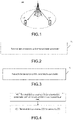
- the communication system 100 may include a network device 110, and the network device 110 may be a device that communicates with the UE 120 (or referred to as a communication terminal device, a terminal device).
- the network device 110 may provide communication coverage for a particular geographic area and may communicate with UEs located within the coverage area.
- the network device 110 may be a network device (Base Transceiver Station, BTS) in a GSM system or a CDMA system, or a network device (NodeB, NB) in a WCDMA system, or an evolution network device (Evolutional Node B, eNB or eNodeB) in an LTE system, or a wireless controller in a cloud radio access network (CRAN), or the network device may be a mobile exchange center, a relay station, an access point, a vehicle-mounted device, a wearable device, a hubs, an exchanger, a bridge, a router, a network-side device in 5G network or a network device in a future evolution network, etc.
- BTS Base Transceiver Station
- NodeB, NB network device
- Evolutional Node B, eNB or eNodeB evolution network device
- LTE Long Term Evolution
- CRAN cloud radio access network
- the network device may be a mobile exchange center, a relay station, an access point
- the communication system 100 further includes at least one UE 120 located within the coverage of the network device 110. There may be wired communication or wireless communication between the UE 120 and the network device 110.
- a UE that communicates wirelessly with the network device 110 may be referred to as a "wireless communication terminal device", a “wireless terminal device” or a “mobile terminal device”.
- An embodiment of the present disclosure provides a transmission parameter determination method, as shown in FIG. 2 , including: Step 21: A terminal device receives a first transmission parameter.
- the first transmission parameter is used to determine the number of bits of a first indication field in the DCI; the first transmission parameter and the second transmission parameter correspond to the first indication field in the DCI.
- An embodiment of the present disclosure further provides a transmission parameter determination method, as shown in FIG. 3 , including: Step 31: A network device sends a first transmission parameter.
- the first transmission parameter is used to determine the number of bits of a first indication field in the DCI; a first transmission parameter set and a second transmission parameter set correspond to the first indication field in the DCI.
- the solution may further include that the terminal device receives the second transmission parameter sent by the network device.
- the step may be that the terminal device receives the second transmission parameter set sent by the network device.
- the terminal device may receive the first transmission parameter set and the second transmission parameter set sent by the network device.
- the first transmission parameter includes: at least one transmission parameter among the transmission parameters of the CG (Configured Grant).
- the second transmission parameter includes: at least one transmission parameter among uplink data transmission parameters, or at least one transmission parameter agreed by a protocol.
- both the first transmission parameter and the second transmission parameter may include one or more transmission parameters.
- the first transmission parameter may be referred to as the first transmission parameter set.
- the second transmission parameter may be regarded as the second transmission parameter set when including multiple transmission parameters.
- the first transmission parameter set (or the second transmission parameter set) may be regarded as the configuration parameter.
- the first transmission parameter set configuration (or the second transmission parameter set configuration) may be regarded as the configuration of the first transmission parameter set, or the configuration of the second transmission parameter set, that is, the value of the configuration parameter.
- rbg size is the first transmission parameter
- the uplink data transmission parameter set configuration may be a transmission parameter set configuration of a PUSCH (Physical Uplink Share Channel).
- PUSCH Physical Uplink Share Channel
- the number of bits of the first indication field determined based on the first transmission parameter set is not greater than the number of bits of the first indication field determined based on the second transmission parameter set. It may be understood that the first transmission parameter set configuration is limited by the second transmission parameter set configuration. More specifically, the following may be included: The number of bits of the first indication field determined based on the first transmission parameter set is less than the number of bits of the first indication field determined based on the second transmission parameter set.
- the number of bits of the first indication field determined based on the first transmission parameter set is equal to the number of bits of the first indication field determined based on the second transmission parameter set.
- the second transmission parameter is a transmission parameter corresponding to the first indication field with the least number of bits in all DCI formats used for uplink scheduling.
- the second transmission parameter set configuration is a transmission parameter set configuration of the first indication field corresponding to the least number of bits in all DCI formats used for uplink scheduling.
- the transmission parameter of the first indication field corresponding to the least number of bits in all DCI formats used for uplink scheduling is interpreted as: the transmission parameter of the first indication field with the least number of bits in all DCI formats used for uplink scheduling, which is used as the second transmission parameter.
- all DCI formats used for uplink scheduling include at least: a DCI format 0-1 and a DCI format 0-2.
- all DCI formats used for uplink scheduling at least include: a DCI format 0-0, a DCI format 0-1, and a DCI format 0-2.
- the number of bits of the first indication field determined by the first parameter (set) configuration in ConfiguredGrantConfig is less than or equal to the number of bits of the first indication field determined by the related second parameter (set) configuration in PUSCH-Config.
- the number of bits of the first indication field determined by the second parameter (set) is the minimum value of the number of bits of the first indication field in all DCI formats supported by the terminal (or all DCI formats used for uplink scheduling).
- the DMRS configuration parameter for DCI format 0-1 in PUSCH-Config (that is, the aforementioned uplink data transmission parameter), such as dmrs-UplinkForPUSCH-MappingTypeA and dmrs-UplinkForPUSCH-MappingTypeB, is configured to: support multi-port transmission, and has 3 bits according to the antenna port field (which can be regarded as the first indication field in this example) in the configured DCI format 0-1.
- the DMRS configuration parameter for DCI format 0-2 in PUSCH-Config (that is, the aforementioned uplink data transmission parameter), such as dmrs-UplinkForPUSCH-MappingTypeA-DCI format 0-2 and dmrs-UplinkForPUSCH-MappingTypeB-DCI format 0-2, is not configured, that is, has 0 bit according to the antenna port field in the configured DCI format 0-2.
- the antenna port field in DCI format 0-0 in PUSCH-Config (that is, the aforementioned uplink data transmission parameter) does not exist. Or, the antenna port field in DCI format 0-0 agreed by the protocol does not exist.
- the antenna port field in DCI format 0-0 does not exist, and which may be interpreted that this field has 0 bit.
- the second transmission parameter set configuration is the transmission parameter set configuration of the first indication field corresponding to the least number of bits in all DCI formats used for uplink scheduling, it means that the second transmission parameter set configuration is the transmission parameter set configuration corresponding to DCI format 0-0 or DCI format 0-2.
- the second transmission parameter set configuration determines that the number of bits of the first indication field is 0, then the bits of the first indication field configured by the first transmission parameter set configuration are also 0. That is to say, it corresponds to the situation that the number of bits of the first indication field determined based on the first transmission parameter set is equal to the number of bits of the first indication field determined based on the second transmission parameter set.
- the DMRS configuration parameter (that is, the first transmission parameter) in ConfiguredGrantConfig is limited to all DCI formats, such as the configuration of DCI formats 0-0/0-1/0-2, therefore, cg-DMRS-Configuration is not configured.
- first transmission parameter set configuration and the second transmission parameter set configuration is also applicable to the terminal device side and the network device side.
- Step 41 The terminal device receives the first transmission parameter (set) and the second transmission parameter (set).
- the terminal device receives ConfiguredGrantConfig (Configuration of CG) and PUSCH-Config (Physical Uplink Share Channel Configuration).
- ConfiguredGrantConfig Configuration of CG
- PUSCH-Config Physical Uplink Share Channel Configuration
- Step 42 The terminal device receives the DCI that activates the Configured Grant.
- the method further includes: determining the number of bits of the first indication field in the DCI for activating the Configured Grant; and the terminal device parses the first indication field according to the first transmission parameter configuration.
- the DCI format for activating the Configured Grant is one of all the DCI formats used for uplink scheduling, or one of all the DCI formats for activating the Configured Grant.
- the first indication field is one of at least one indication field of the DCI for activating the Configured Grant.
- the step of determining the number of bits of the first indication field in the DCI that activates the Configured Grant may be: determining the number of bits of the first indication field according to at least one transmission parameter in the uplink data transmission parameters.
- the step of determining the number of bits of the first indication field in the DCI for activating the Configured Grant may be: determining the number of bits of the first indication field according to at least one transmission parameter in the uplink data transmission parameters corresponding to the DCI format for activating the Configured Grant.
- the first indication field is one of multiple DCI fields included in the DCI that activates the Configured Grant. That is to say, one DCI may contain multiple indication fields, and these indication fields can be respectively interpreted as the first indication field. Different first indication fields may correspond to different second transmission parameter set configurations and first transmission parameter set configurations (on the network device side). However, for different first indication fields, the constraint rules for the related second transmission parameter set configuration and the first transmission parameter set configuration are the same as those described above in this example, so no further description is incorporated herein.
- the DCI that activates the Configured Grant received by the terminal adopts the DCI format 0-1.
- the DMRS configuration parameter for DCI format 0-1 in PUSCH-Config that is, at least one transmission parameter in the uplink data transmission parameter corresponding to the DCI format that activates the Configured Grant
- the antenna port field that is, the first indication field
- the network device side may determine, according to the first transmission parameter configuration, that no configuration is to be performed in the first indication field in the sent DCI that activates Configured Grant.
- the first transmission parameter or the second transmission parameter is at least one of the following: Demodulation reference signal DMRS port related parameters, frequency domain frequency hopping parameters, frequency domain resource parameters, parameters of uplink control information UCI multiplexed to physical uplink share channel PUSCH, and DMRS sequence initialization parameters.
- the first transmission parameter set or the second transmission parameter set is at least one of the following: Frequency domain frequency hopping parameter set (for example, frequencyHopping), frequency domain resource parameter set (for example, ResourceAllocationTypel-Granularity), parameter set (for example, uci-onPUSCH) of uplink control information (UCI) multiplexed to the physical uplink share channel (PUSCH), DMRS sequence initialization parameter set (for example, DMRSsequenceinitialization), and DMRE port related parameter set.
- Frequency domain frequency hopping parameter set for example, frequencyHopping
- frequency domain resource parameter set for example, ResourceAllocationTypel-Granularity
- parameter set for example, uci-onPUSCH
- UCI uplink control information
- PUSCH physical uplink share channel
- DMRS sequence initialization parameter set for example, DMRSsequenceinitialization
- DMRE port related parameter set for example, DMRE port related parameter set.
- the target transmission parameter configuration set may further include more parameters, which may be set according to actual conditions, and will not be further described here.
- the second transmission parameter is a transmission parameter corresponding to the first indication field with the least number of bits in the DCI format used for Configured Grant transmission.
- the second transmission parameter set configuration is a transmission parameter set configuration of the first indication field corresponding to the least number of bits in the DCI format used for Configured Grant transmission.
- the second transmission parameter is the transmission parameter corresponding to the first indication field with the least number of bits in the DCI format used for the Configured Grant transmission, which can be interpreted as: the transmission parameter corresponding to the first indication field with the least number of bits in the DCI format used for Configured Grant transmission is used as the second transmission parameter.
- the DCI used to transmit the Configured Grant may be the DCI used to activate the Configured Grant, or may be the DCI used to retransmit the Configured Grant.
- the DCI for activating the Configured Grant is taken as an example for description.
- the number of bits of the first indication field determined by the first parameter (set) in ConfiguredGrantConfig is less than or equal to the number of bits of the first indication field determined by the related second parameter (set) in PUSCH-Config.
- the number of bits of the first indication field determined by the second parameter (set) is the minimum value of the number of bits of the first indication field in all DCI formats used to activate the Configured Grant.
- the DMRS configuration parameter for DCI format 0-1 in PUSCH-Config (that is, the aforementioned uplink data transmission parameter), such as dmrs-UplinkForPUSCH-MappingTypeA and dmrs-UplinkForPUSCH-MappingTypeB, is configured to support multi-port transmission, and the antenna port field in DCI format 0-1 having 4 bit is configured according to the DMRS configuration parameter.
- DMRS configuration parameter for DCI format 0-2 in PUSCH-Config (that is, the aforementioned uplink data transmission parameter), such as dmrs-UplinkForPUSCH-MappingTypeA-DCI format 0-2 and dmrs-UplinkForPUSCH-MappingTypeB-DCI format 0-2, is configured to support multi-port transmission, and the antenna port field (that is, the first indication field) having 3 bits in DCI format 0-2 is configured according to the SMRS configuration parameter.
- the default antenna port field in DCI format 0-0 in PUSCH-Config (that is, the aforementioned uplink data transmission parameter) does not exist, or the first indication field of DCI format 0-0 as agreed in the protocol does not exist.
- the pre-configured DCI format 0-1 and DCI format 0-2 are all DCI formats used for Configured Grant transmission, then the second transmission parameter set configuration is the transmission parameter set configuration corresponding to the antenna port field (that is, the first indication field) having 3 bits.
- the number of bits of the first indication field determined based on the first transmission parameter set configuration is not greater than the number of bits of the first indication field determined based on the second transmission parameter set configuration. That is, when the number of bits of the first indication field determined by the second transmission parameter set configuration is 3, then the bits of the first indication field corresponding to the first transmission parameter set configuration are less than or equal to 3 bits.
- the DMRS configuration parameter (that is, the first transmission parameter set) in ConfiguredGrantConfig is limited to all DCI formats used to activate ConfiguredGrant, such as DCI format 0-1/0-2 configuration. Therefore, cg-DMRS-Configuration may also be configured to support multi-port transmission, and the corresponding antenna port field is 3 bits at maximum, and may be less than 3 bits, such as 2 bits, or may be equal to 3 bits. This example adopts 3 bits as an example.
- first transmission parameter set configuration and the second transmission parameter set configuration is also applicable to the terminal device side and the network device side.
- the processing flow for this example may be:
- the method further includes: determining the number of bits of the first indication field in the DCI for activating the Configured Grant; and the terminal device parses the first indication field according to the first transmission parameter configuration.
- the DCI format for activating the Configured Grant is one of all the DCI formats used for uplink scheduling, or one of all the DCI formats for activating the Configured Grant.
- the first indication field is one of at least one indication field of the DCI for activating the Configured Grant.
- the step of determining the number of bits of the first indication field in the DCI that activates the Configured Grant may be: determining the number of bits of the first indication field according to at least one transmission parameter in the uplink data transmission parameters.
- the step of determining the number of bits of the first indication field in the DCI for activating the Configured Grant may be: determining the number of bits of the first indication field according to at least one transmission parameter in the uplink data transmission parameters corresponding to the DCI format for activating the Configured Grant.
- the DCI that activates the Configured Grant received by the terminal adopts the DCI format 0-1.
- the DMRS configuration parameter for DCI format 0-1 in PUSCH-Config that is, at least one transmission parameter in the uplink data transmission parameter corresponding to the DCI format that activates the Configured Grant
- the antenna port field has 4 bits.
- the terminal device only interprets 3 bits in the antenna port field.
- the network device side may determine, according to the first transmission parameter configuration, to perform configuration corresponding to 3 bits in the first indication field in the sent DCI that activates the Configured Grant.
- the first transmission parameter or the second transmission parameter is at least one of the following: Demodulation reference signal DMRS port related parameters, frequency domain frequency hopping parameters, frequency domain resource parameters, parameters of uplink control information UCI multiplexed to physical uplink shared channel PUSCH, and DMRS sequence initialization parameters.
- the first transmission parameter set or the second transmission parameter set is at least one of the following: Frequency domain frequency hopping parameter set (for example, frequencyHopping), frequency domain resource parameter set (for example, ResourceAllocationTypel-Granularity), parameter set (for example, uci-onPUSCH) of uplink control information (UCI) multiplexed to the physical uplink share channel (PUSCH), DMRS sequence initialization parameter set (for example, DMRSsequenceinitialization), and DMRE port related parameter set.
- Frequency domain frequency hopping parameter set for example, frequencyHopping
- frequency domain resource parameter set for example, ResourceAllocationTypel-Granularity
- parameter set for example, uci-onPUSCH
- UCI uplink control information
- PUSCH physical uplink share channel
- DMRS sequence initialization parameter set for example, DMRSsequenceinitialization
- DMRE port related parameter set for example, DMRE port related parameter set.
- the target transmission parameter configuration set may further include more parameters, which may be set according to actual conditions, and will not be further described here.
- the second transmission parameter is the transmission parameter corresponding to the first indication field with the largest number of bits in all DCI formats used for uplink scheduling; or, the second transmission parameter is the transmission parameter corresponding to the first indication field with the largest number of bits in the DCI format used for Configured Grant transmission.
- the number of bits of the first indication field determined by the first parameter (set) in ConfiguredGrantConfig is less than or equal to the number of bits of the first indication field determined by the related second parameter (set) in PUSCH-Config.
- the number of bits of the first indication field determined by the second parameter (set) is the maximum value of the number of bits of the related first indication field in all DCI formats used for Configured Grant transmission.
- the number of bits of the first indication field determined by the second parameter (set) is the maximum value of the number of bits of the first indication field in all DCI formats used for uplink scheduling.
- the Configured Grant transmission may be used for activating the Configured Grant or scheduled for the Configured Grant retransmission.
- the DMRS configuration parameter for DCI format 0-1 in PUSCH-Config (that is, the aforementioned uplink data transmission parameter), such as dmrs-UplinkForPUSCH-MappingTypeA and dmrs-UplinkForPUSCH-MappingTypeB, is configured to support multi-port transmission, and the antenna port field having 4 bits in DCI format 0-1 is configured according to the DMRS configuration parameter.
- the DMRS configuration parameter for DCI format 0-2, such as dmrs-UplinkForPUSCH-MappingTypeA-DCI format 0-2 and dmrs-UplinkForPUSCH-MappingTypeB-DCI format 0-2, is configured to support multi-port transmission, and the antenna port field having 3 buts in DCI format 0-2 is configured according to the DMRS configuration parameter.
- the default antenna port field in DCI format 0-0 does not exist.
- the second transmission parameter set configuration is the maximum value of the number of bits of the relevant first indication field in all DCI formats supported by the terminal device, and the second transmission parameter set configuration may be the DMRS configuration parameter of DCI format 0-1.
- the DMRS configuration parameter (first transmission parameters) in ConfiguredGrantConfig is limited to all DCI formats. Therefore, cg-DMRS-Configuration may also be configured to support multi-port transmission, and the corresponding antenna port field has 4 bits at maximum. That is to say, the number of bits of the first indication field corresponding to the first transmission parameter may be less than 4 bits, for example, may be 2 bits, or 3 bits, and of course may be equal to 4 bits. In this example, 4 bits are adopted as an example.
- the second transmission parameter set configuration may be DMRS configuration parameter of DCI format 0-1.
- the DMRS configuration parameter (first transmission parameter set) in ConfiguredGrantConfig is limited to all DCI formats used to activate ConfiguredGrant, such as the configuration of DCI format 0-1/0-2. Therefore, cg-DMRS-Configuration may also be configured to support multi-port transmission, and the corresponding antenna port field has 4 bits at maximum.
- Condition 1 In a case that the DCI for activating the Configured Grant is the third DCI format, parsing the first indication field according to the first transmission parameter.
- the third DCI format is DCI format 0-1.
- the network device configures the first indication field according to the first transmission parameter in a case that the DCI to be sent for activating the Configured Grant is the third DCI format.
- the method may further include: in a case that the DCI for activating the Configured Grant is the third DCI format, the number of bits of the first indication field is determined according to the second transmission parameter, and paraing the first indication field according to the first transmission parameter.
- the antenna port field has 4 bits.
- the 4 bits in the antenna port field are parsed.
- Condition 2 In the case that the DCI that activates the Configured Grant is the fourth DCI format, parsing the first indication field according to the first transmission parameter.
- the DCI for activating the Configured Grant is the fourth DCI format, parsing the first indication field according to the second transmission parameter; or,
- the DCI for activating the Configured Grant is the fourth DCI format, parsing the first indication field according to the first transmission parameter and the second transmission parameter.
- the fourth DCI format is DCI 0-2.
- the method may also include: in the case that the DCI for activating the Configured Grant is the third DCI format, the number of bits of the first indication field is determined according to the second transmission parameter set configuration, and parsing the first indication field according to the first transmission parameter set configuration and/or parsing the first indication field according to the second transmission parameter set configuration.
- the DCI that activates the Configured Grant received by the terminal adopts DCI format 0-2, according to the DMRS configuration parameter (second transmission parameter) for DCI format 0-2 in PUSCH-Config, such as dmrs-UplinkForPUSCH-MappingTypeA-DCIformat0-2 and dmrs-UplinkForPUSCH-MappingTypeB-DCIformat0-2, it is determined that the antenna port field has 3 bits.
- Condition 2.1 The terminal parses the 3 bits in the antenna port field, and determines the information indicated by the antenna port according to the DMRS configuration parameter (the first transmission parameter) in the Configured Grant, such as cg-DMRS-Configuration.
- bits of the first indication field determined according to the first transmission parameter set configuration are greater than the number of bits of the first indication field determined by the second transmission parameter set configuration, that is:
- the DCI for activating the Configured Grant is the fourth DCI format
- the first indication field corresponds to the part of the value corresponding to the first transmission parameter set configuration
- cg-DMRS-Configuration determines that the antenna port supports 16 configurations, namely ⁇ 0, 1, 2, 3, 4, 5, 6, 7, 0-1, 2-3, 4-5, 6-7, 0-3, 4-7,0-5, 0-7 ⁇ , but since the antenna port field has only 3 bits, it only corresponds to the first 8 configurations in the configuration, or corresponds to the single-port configuration in the configuration.
- Condition 2.2 The terminal parses the 3 bits in the antenna port field, and determines the information indicated by the antenna port (the first indication field) according to the DMRS configuration parameter (second transmission parameter) for DCI format 0-2 in PUSCH-Config, such as dmrs-UplinkForPUSCH-MappingTypeA-DCIformat0-2 and dmrs-UplinkForPUSCH-MappingTypeB-DCIformat0-2.
- the network device may configure the information indicated by the first indication field according to the second transmission parameter set configuration.
- Terminal can perform the following: According to the DMRS configuration parameter (second transmission parameter) for DCI format 0-2 in PUSCH-Config, such as dmrs-UplinkForPUSCH-MappingTypeA-DCIformat0-2 and dmrs-UplinkForPUSCH-MappingTypeB-DCIformat0-2, and the first transmission parameter, such as cg-DMRS-Configuration, jointly determines the information indicated by the antenna port.
- the DMRS configuration parameter for DCI format 0-2 in PUSCH-Config, such as dmrs-UplinkForPUSCH-MappingTypeA-DCIformat0-2 and dmrs-UplinkForPUSCH-MappingTypeB-DCIformat0-2
- the first transmission parameter such as cg-DMRS-Configuration
- the FDRA field (which can be interpreted as the first indication field) in DCI format 0-2 may be jointly determined according to resource allocation and/or rbg (which can be interpreted as the first transmission parameter) in ConfiguredgrantConfig and ResourceAllocationType1-Granularity (which may be interpreted as the second transmission parameter) in PUSCHConfig.
- the second transmission parameter is a transmission parameter corresponding to the first indication field of the first DCI format
- the first DCI format is one of all the DCI formats used for uplink scheduling.
- the second transmission parameter (set) is the transmission parameter corresponding to the first indication field of the specified first DCI format.
- the first DCI format is agreed by the protocol or configured by the network. That is, the specified first DCI format is specified by the protocol, for example, in some cases, only the first DCI format can be used for transmission; alternatively, it may be that the network device specifies only the first DCI format is adopted for transmission at a certain occasion (or within a certain period of time).
- the first DCI format is DCI format 0-1.
- the first DCI format may also be other formats, as long as it is a specified format determined according to a protocol agreement or network device configuration, for example, the first DCI format may be DCI formats 0-2, etc., no further description is provided herein.
- the second transmission parameter may be used for determining the number of bits of the first indication field in the DCI; then, the first indication field may be parsed through the first transmission parameter set configuration.
- the protocol stipulates that the second transmission parameter set configuration is used to parse the first indication field.
- the DMRS configuration parameter (second transmission parameter) for DCI format 0-1 in PUSCH-Config such as dmrs-UplinkForPUSCH-MappingTypeA and dmrs-UplinkForPUSCH-MappingTypeB, is configured to support multi-port transmission, and the antenna port field (the first indication field) having 4 bits in the DCI format 0-1 is configured according to the DMRS configuration parameter.
- the 4 bits in the antenna port field may be interpreted (or configured) according to the second transmission parameter set configuration (or the first transmission parameter).
- the second transmission parameter is a transmission parameter corresponding to the first indication field of the second DCI format
- the second DCI format is one of all the DCI formats used for Configured Grant transmission.
- the second DCI format is one of all DCI formats used for the Configured Grant transmission.
- the second DCI format may also be agreed by a protocol or configured by a network.
- the second DCI format is DCI format 0-1.
- the second DCI format may also be other formats, as long as it is a specified format determined according to a protocol agreement or network device configuration, for example, the second DCI format may be DCI format 0-2, etc., and no further description is not incorporated herein.
- the network device sends the DCI that retransmits the Configured Grant; correspondingly, the terminal device receives the DCI that retransmits the Configured Grant.
- the DCI format for retransmitting the Configured Grant is consistent with the DCI format for activating the Configured Grant.
- the DCI format for activating the Configured Grant needs to be consistent with the scheduling DCI format for retransmitting the Configured Grant.
- the terminal receives the first DCI sent by the network device to activate the Configured Grant, and the first DCI is the first DCI format.
- the terminal receives the second DCI sent by the network device for scheduling retransmission of the Configured Grant, and the second DCI is the second DCI format.
- the second DCI format is the same as the first DCI format.
- the initial transmission and retransmission of the Configured Grant can maintain a consistent transmission configuration and reduce the complexity of the terminal.
- the processing method for the DCI configured for retransmitting the Configured Grant may be the same as the foregoing example, and details are not repeated here.
- the network device sends the DCI that retransmits the Configured Grant; correspondingly, the terminal device receives the DCI that retransmits the Configured Grant.
- the DCI format configured for retransmitting the Configured Grant is independent of the DCI format configured for activating the Configured Grant.
- the DCI format for activating the Configured Grant may be inconsistent with the scheduling DCI format for retransmitting the Configured Grant.
- the terminal receives the first DCI for activating the Configured Grant, and the first DCI is the first DCI format.
- the terminal receives the second DCI for scheduling the retransmission of the Configured Grant, and the second DCI is a second DCI format.
- the second DCI format is independently configured from the first DCI format, and they may be the same or different.
- the content of the first indication field in the DCI for retransmitting the Configured Grant is parsed by using the same first transmission parameter set configuration as the DCI format that activates the Configured Grant; or, the content of the first indication field in the DCI for retransmitting the Configured Grant is parsed by adopting the first transmission parameter set configuration corresponding to the DCI for retransmitting the Configured Grant.
- the configuration of) the first transmission parameter in this example is limited by (the configuration of) the second transmission parameter, and may be applicable to all transmission parameters.
- the above condition may be applicable to some parameters, for example, the first transmission parameter or the second transmission parameter is at least one of the following: Demodulation reference signal DMRS port related parameters, frequency domain frequency hopping parameters, frequency domain resource parameters, parameters of uplink control information UCI multiplexed to physical uplink share channel PUSCH, and DMRS sequence initialization parameters.
- the first transmission parameter or the second transmission parameter is at least one of the following: Demodulation reference signal DMRS port related parameters, frequency domain frequency hopping parameters, frequency domain resource parameters, parameters of uplink control information UCI multiplexed to physical uplink share channel PUSCH, and DMRS sequence initialization parameters.
- the first transmission parameter set or the second transmission parameter set is at least one of the following: Frequency domain frequency hopping parameter set (for example, frequencyHopping), frequency domain resource parameter set (for example, ResourceAllocationTypel-Granularity), parameter set (for example, uci-onPUSCH) of uplink control information (UCI) multiplexed to the physical uplink share channel (PUSCH), DMRS sequence initialization parameter set (for example, DMRSsequenceinitialization), and DMRE port related parameter set.
- Frequency domain frequency hopping parameter set for example, frequencyHopping
- frequency domain resource parameter set for example, ResourceAllocationTypel-Granularity
- parameter set for example, uci-onPUSCH
- UCI uplink control information
- PUSCH physical uplink share channel
- DMRS sequence initialization parameter set for example, DMRSsequenceinitialization
- DMRE port related parameter set for example, DMRE port related parameter set.
- the first transmission parameter set configuration sent by the network device to the terminal device is limited by the second transmission parameter set configuration; and the first transmission parameter set and the second transmission parameter set correspond to the first indication field in the DCI. Therefore, the transmission parameter set configuration corresponding to the indication field of the same DCI has a constraint relationship. In this manner, it is possible to solve the problem of different number of bits of a certain indication field in the DCI corresponding to different transmission parameter set configurations.
- An embodiment of the present disclosure provides a terminal device, as shown in FIG. 6 , including: A first communication unit 61 receives the first transmission parameter set configuration.
- the first transmission parameter is configured to determine the number of bits of the first indication field in the DCI; the first transmission parameter set and the second transmission parameter set correspond to the first indication field in the DCI.
- An embodiment of the present disclosure further provides a transmission network device, as shown in FIG. 7 , including: A second communication unit 71 receives the first transmission parameter set configuration.
- the first transmission parameter is configured to determine the number of bits of the first indication field in the DCI; the first transmission parameter set and the second transmission parameter set correspond to the first indication field in the DCI.
- the first transmission parameter includes: at least one transmission parameter in the transmission parameters of the Configured Grant.
- the second transmission parameter includes: at least one transmission parameter in the uplink data transmission parameters, or at least one transmission parameter agreed by a protocol.
- both the first transmission parameter and the second transmission parameter may include one or more transmission parameters.
- the first transmission parameter may be referred to as the first transmission parameter set.
- the second transmission parameter may be regarded as the second transmission parameter set when including multiple transmission parameters.
- the number of bits of the first indication field determined based on the first transmission parameter set is not greater than the number of bits of the first indication field determined based on the second transmission parameter set. It can be interpreted that the first transmission parameter set configuration is limited by the second transmission parameter set configuration. More specifically, the following may be included: The number of bits of the first indication field determined based on the first transmission parameter set is less than the number of bits of the first indication field determined based on the second transmission parameter set.
- the number of bits of the first indication field determined based on the first transmission parameter set is equal to the number of bits of the first indication field determined based on the second transmission parameter set.
- the second transmission parameter is a transmission parameter corresponding to the first indication field with the least number of bits in all DCI formats used for uplink scheduling.
- the second transmission parameter set configuration is a transmission parameter set configuration of the first indication field corresponding to the least number of bits in all DCI formats used for uplink scheduling.
- the transmission parameters of the first indication field corresponding to the least number of bits in all DCI formats used for uplink scheduling are interpreted as: the transmission parameter with the least number of bits in the first indication field in all DCI formats used for uplink scheduling is used as the second transmission parameter.
- the first transmission parameter set may be composed of at least one transmission parameter in the transmission parameters of the Configured Grant.
- the second transmission parameter set may be composed of at least one transmission parameter in the uplink data transmission parameters, or composed of at least one transmission parameter agreed in the protocol.
- all DCI formats used for uplink scheduling include at least: DCI format 0-1 and DCI format 0-2.
- all DCI formats used for uplink scheduling at least include: DCI format 0-0, DCI format 0-1, and DCI format 0-2.
- the first communication unit of the terminal device receives the first transmission parameter set configuration and the second transmission parameter set configuration.
- the terminal device receives ConfiguredGrantConfig and PUSCH-Config (Physical Uplink Share Channel Configuration).
- ConfiguredGrantConfig Physical Uplink Share Channel Configuration
- PUSCH-Config Physical Uplink Share Channel Configuration
- the first communication unit of the terminal device receives the DCI that activates the Configured Grant.
- the first processing unit 62 further included in the terminal device determines the number of bits of the first indication field in the DCI that activates the Configured Grant.
- the first processing unit 62 of the terminal device parses the first indication field according to the first transmission parameter configuration.
- the DCI format for activating the Configured Grant is one of all the DCI formats used for uplink scheduling, or one of all the DCI formats for activating the Configured Grant.
- the first indication field is one of at least one indication field of the DCI for activating the Configured Grant.
- the first processing unit 62 of the terminal device determines the number of bits of the first indication field according to at least one transmission parameter in the uplink data transmission parameters.
- the network device may further include a second processing unit 72, which determines the number of bits of the first indication field according to at least one transmission parameter in the uplink data transmission parameters.
- the first indication field is one of multiple DCI fields included in the DCI that activates the Configured Grant. That is to say, one DCI may contain multiple indication fields, and these indication fields can be respectively regarded as the first indication field. Different first indication fields may correspond to different second transmission parameter set configurations and first transmission parameter set configurations (on the network device side). However, for different first indication fields, the constraint rules for the related second transmission parameter set configurations and the first transmission parameter set configurations are the same as those described above in this example, so no further details are repeated here.
- the first transmission parameter or the second transmission parameter is at least one of the following: Demodulation reference signal DMRS port related parameters, frequency domain frequency hopping parameters, frequency domain resource parameters, parameters of uplink control information UCI multiplexed to physical uplink share channel PUSCH, and DMRS sequence initialization parameters.
- the first transmission parameter set or the second transmission parameter set is at least one of the following: Frequency domain frequency hopping parameter set (for example, frequencyHopping), frequency domain resource parameter set (for example, ResourceAllocationTypel-Granularity), parameter set (for example, uci-onPUSCH) of uplink control information (UCI) multiplexed to the physical uplink share channel (PUSCH), DMRS sequence initialization parameter set (for example, DMRSsequenceinitialization), and DMRE port related parameter set.
- Frequency domain frequency hopping parameter set for example, frequencyHopping
- frequency domain resource parameter set for example, ResourceAllocationTypel-Granularity
- parameter set for example, uci-onPUSCH
- UCI uplink control information
- PUSCH physical uplink share channel
- DMRS sequence initialization parameter set for example, DMRSsequenceinitialization
- DMRE port related parameter set for example, DMRE port related parameter set.
- the target transmission parameter set configuration may further include more parameters, which may be set according to actual conditions, and no further details are incorporated here.
- the second transmission parameter is a transmission parameter corresponding to the first indication field with the least number of bits in the DCI format used for Configured Grant transmission.
- the second transmission parameter set configuration is a transmission parameter set configuration of the first indication field corresponding to the least number of bits in the DCI format used for the Configured Grant transmission.
- the second transmission parameter is the transmission parameter corresponding to the first indication field with the least number of bits in the DCI format used for the Configured Grant transmission, which may be interpreted as: the transmission parameter corresponding to the least number of bits corresponding to the first indication field in the DCI format used for Configured Grant transmission is used as the second transmission parameter.
- the first transmission parameter set may be composed of at least one transmission parameter in the transmission parameters of the Configured Grant.
- the second transmission parameter set may be composed of at least one transmission parameter in the uplink data transmission parameters, or composed of at least one transmission parameter agreed in the protocol.
- the number of bits of the first indication field determined by the second parameter (set) is the minimum value of the number of bits of the first indication field in all DCI formats used to activate the Configured Grant.
- the first communication unit 61 of the terminal device receives the first transmission parameter set configuration and the second transmission parameter set configuration.
- the first communication unit 61 of the terminal device receives the DCI that activates the Configured Grant.
- the first processing unit 62 of the terminal device determines the number of bits of the first indication field in the DCI that activates the Configured Grant; the terminal device parses the first indication field according to the first transmission parameter configuration.
- the DCI format for activating the Configured Grant is one of all the DCI formats used for uplink scheduling, or one of all the DCI formats for activating the Configured Grant.
- the first indication field is one of at least one indication field of the DCI for activating the Configured Grant.
- the first processing unit 62 of the terminal device or the second processing unit 72 of the network device determines the number of bits of the first indication field according to at least one transmission parameter in the uplink data transmission parameters.
- the second transmission parameter is the transmission parameter corresponding to the first indication field with the largest number of bits in all DCI formats used for uplink scheduling.
- the second transmission parameter is the transmission parameter corresponding to the first indication field with the largest number of bits in the DCI format used for Configured Grant transmission.
- the number of bits of the first indication field determined by the second parameter (set) is the maximum value of the number of bits of the first indication field in all DCI formats used for Configured Grant transmission.
- the number of bits of the first indication field determined by the second parameter (set) may be used for the maximum value of the number of bits of the first indication field in all DCI formats used for uplink scheduling.
- the Configured Grant transmission may be scheduled for activating the Configured Grant or the Configured Grant retransmission.
- the first communication unit 61 of the terminal device receives the DCI that activates the Configured Grant, and the first processing unit 62 of the terminal device determines a corresponding transmission parameter set configuration according to the DCI format of the DCI that activates the Configured Grant, and parses the DCI that activates the Configured Grant.
- the first processing unit 62 of the terminal device parses the first indication field according to the first transmission parameter set configuration in a case that the DCI for activating the Configured Grant is the third DCI format.
- the third DCI format is DCI format 0-1.
- the second processing unit of the network device configures the first indication field according to the first transmission parameter set configuration in the case that the DCI to be sent to activate the Configured Grant is the third DCI format.
- the condition may further include: in the case that the DCI for activating the Configured Grant is the third DCI format, determining the number of bits of the first indication field according to the second transmission parameter, and parsing the first indication field according to the first transmission parameter.
- the first processing unit 62 of the terminal device parses the first indication field according to the first transmission parameter in a case that the DCI for activating the Configured Grant is the fourth DCI format.
- the DCI for activating the Configured Grant is the fourth DCI format, parsing the first indication field according to the second transmission parameter; or,
- the DCI for activating the Configured Grant is the fourth DCI format, parsing the first indication field according to the first transmission parameter and the second transmission parameter.
- the fourth DCI format is DCI 0-2.
- the DCI for activating the Configured Grant is the fourth DCI format
- the first processing unit 62 of the terminal device determines that, according to the second transmission parameter, the number of bits of the first indication field is less than the number of bits of the first indication field determined according to the first transmission parameter set configuration, then the first indication field corresponds to part of the value corresponding to the first transmission parameter.
- Condition 2.2 The terminal parses the 3 bits in the antenna port field, and configures parameters (second transmission parameters) according to the DMRS for DCI format 0-2 in PUSCH-Config, such as dmrs-UplinkForPUSCH-MappingTypeA-DCIformat0-2 and dmrs-UplinkForPUSCH-MappingTypeB-DCIformat0-2, thus determining the information indicated by the antenna port.
- parameters second transmission parameters
- the terminal parses the 3 bits in the antenna port field, and configures parameters (second transmission parameters) according to the DMRS for DCI format 0-2 in PUSCH-Config, such as dmrs-UplinkForPUSCH-MappingTypeA-DCIformat0-2 and dmrs-UplinkForPUSCH-MappingTypeB-DCIformat0-2, and the first transmission parameter set configuration, such as cg-DMRS-Configuration, thus jointly determining the information indicated by the antenna port.
- parameters (second transmission parameters) according to the DMRS for DCI format 0-2 in PUSCH-Config, such as dmrs-UplinkForPUSCH-MappingTypeA-DCIformat0-2 and dmrs-UplinkForPUSCH-MappingTypeB-DCIformat0-2
- the first transmission parameter set configuration such as cg-DMRS-Configuration
- the second transmission parameter set configuration is a transmission parameter set configuration corresponding to the first indication field of the first DCI format
- the first DCI format is one of all the DCI formats used for uplink scheduling.
- the second transmission parameter set configuration is the transmission parameter set configuration corresponding to the first indication field of the specified first DCI format.
- the first DCI format is agreed by the protocol or configured by the network. That is, the specified first DCI format is specified by the protocol, for example, in some cases, only the first DCI format can be used for transmission; or, it may be that the network device specifies that only the first DCI format is used for transmission at a certain occasion (or within a certain period of time).
- the first DCI format is DCI format 0-1.
- the second transmission parameter may be used to determine the number of bits of the first indication field in the DCI. Then, the first indication field may be parsed through the first transmission parameter, or the protocol stipulates that the second transmission parameter is used to parse the first indication field.
- the second transmission parameter set configuration is a transmission parameter corresponding to the first indication field in the second DCI format, and the second DCI format is one of all DCI formats used for the Configured Grant transmission.
- the second DCI format is one of all DCI formats used for the Configured Grant transmission. Specifically, the second DCI format may also be agreed by a protocol or configured by a network. The second DCI format is DCI format 0-1. Other details will not be repeated here.
- the network device sends the DCI that retransmits the Configured Grant; correspondingly, the terminal device receives the DCI that retransmits the Configured Grant.
- the DCI format for retransmitting Configured Grant is consistent with the DCI format for activating the Configured Grant.
- the DCI format for activating the Configured Grant needs to be consistent with the scheduling DCI format for retransmitting the Configured Grant.
- the terminal receives the first DCI sent by the network device to activate the Configured Grant, and the first DCI is in the first DCI format.
- the terminal receives the second DCI sent by the network device for scheduling retransmission of the Configured Grant, and the second DCI is in the second DCI format.
- the second DCI format is the same as the first DCI format.
- the initial transmission and retransmission of the Configured Grant can maintain a consistent transmission configuration and reduce the complexity of the terminal.
- the processing method for retransmitting the DCI of the Configured Grant may be the same as the foregoing example, and details are not repeated here.
- the network device sends the DCI that retransmits the Configured Grant; correspondingly, the terminal device receives the DCI that retransmits the Configured Grant.
- the DCI format for retransmitting the Configured Grant is independent of the DCI format for activating the Configured Grant.
- the DCI format for activating the Configured Grant may be inconsistent with the scheduling DCI format for retransmitting the Configured Grant.
- the terminal receives the first DCI for activating Configured Grant, and the first DCI is the first DCI format.
- the terminal receives the second DCI for scheduling the retransmission of the Configured Grant, and the second DCI is a second DCI format.
- the second DCI format is independently configured from the first DCI format, and they may be the same as or different from each other.
- the content of the first indication field in the DCI of the retransmitted Configured Grant is parsed by using the first transmission parameter set configuration which is the same as the DCI format that activates the Configured Grant; or, the content of the first indication field in the DCI for retransmitting Configured Grant is parsed by using the first transmission parameter set configuration corresponding to the DCI for retransmitting the Configured Grant.
- the first transmission parameter set configuration in this example is limited to the second transmission parameter set configuration, and may be applicable to all transmission parameters.
- the first transmission parameter or the second transmission parameter is at least one of the following: Demodulation reference signal DMRS port related parameters, frequency domain frequency hopping parameters, frequency domain resource parameters, parameters of uplink control information UCI multiplexed to physical uplink share channel PUSCH, and DMRS sequence initialization parameters.
- the first transmission parameter set or the second transmission parameter set is at least one of the following: Frequency domain frequency hopping parameter set (for example, frequencyHopping), frequency domain resource parameter set (for example, ResourceAllocationType1-Granularity), parameter set (for example, uci-onPUSCH) of uplink control information (UCI) multiplexed to the physical uplink share channel (PUSCH), DMRS sequence initialization parameter set (for example, DMRSsequenceinitialization), and DMRE port related parameter set.
- Frequency domain frequency hopping parameter set for example, frequencyHopping
- frequency domain resource parameter set for example, ResourceAllocationType1-Granularity
- parameter set for example, uci-onPUSCH
- UCI uplink control information
- PUSCH physical uplink share channel
- DMRS sequence initialization parameter set for example, DMRSsequenceinitialization
- DMRE port related parameter set for example, DMRE port related parameter set.
- the first transmission parameter set configuration sent by the network device to the terminal device is limited by the second transmission parameter set configuration; and the first transmission parameter set and the second transmission parameter set correspond to the first indication field in the DCI. Therefore, the transmission parameter set configuration corresponding to the indication field of the same DCI has a constraint relationship. In this manner, it is possible to solve the problem of different number of bits of a certain indication field in the DCI corresponding to different transmission parameter set configurations.
- FIG. 8 is a schematic structural view of a communication device 800 according to an embodiment of the present disclosure.
- the communication device in this embodiment may be specifically one of a terminal device and a network device in the foregoing embodiments.
- the communication device 800 shown in FIG. 8 includes a processor 810, and the processor 810 may invoke and execute a computer program from a memory to implement the method in the embodiment of the present disclosure.
- the communication device 800 may further include a memory 820.
- the processor 810 may invoke and execute a computer program from the memory 820 to implement the method in the embodiment of the present disclosure.
- the memory 820 may be a separate device independent of the processor 810, or may be integrated in the processor 810.
- the communication device 800 may further include a transceiver 830, and the processor 810 may control the transceiver 830 to communicate with other devices, specifically, may send information or data to other devices, or receive information or data sent by other devices.
- the transceiver 830 may include a transmitter and a receiver.
- the transceiver 830 may further include antennas, and the number of the antennas may be one or more.
- the communication device 800 may specifically be a network device in this embodiment of the present disclosure, and the communication device 800 may implement the corresponding processes implemented by the network device in various methods in the embodiment of the present disclosure. For brevity, details are not repeated here.
- the communication device 800 may specifically be a terminal device or a network device in the embodiment of the present disclosure, and the communication device 800 may implement the corresponding processes implemented by the mobile terminal/terminal device in various methods of the embodiment of the present disclosure. For brevity, details are not repeated here.
- the first processing unit of the above terminal device may be implemented by the processor 810 in the communication device 800; or, the second processing unit of the network device may be implemented by the processor 810 in the communication device 800.
- the first communication unit of the above terminal device may be implemented by the transceiver 830 in the communication device 800; or, the second communication unit of the network device may be implemented by the transceiver 830 of the communication device 800.
- FIG. 9 is a schematic structural view of a chip according to an embodiment of the present disclosure.
- the chip 900 shown in FIG. 9 includes a processor 910, and the processor 910 may invoke and execute a computer program from a memory to implement the method in the embodiment of the present disclosure.
- the chip 900 may further include a memory 920.
- the processor 910 may invoke and execute a computer program from the memory 920 to implement the method in the embodiment of the present disclosure.
- the memory 920 may be a separate device independent of the processor 910, or may be integrated in the processor 910.
- the chip 900 may further include an input interface 930.
- the processor 910 may control the input interface 930 to communicate with other devices or chips, and specifically, may acquire information or data sent by other devices or chips.
- the chip 900 may further include an output interface 940.
- the processor 910 may control the output interface 940 to communicate with other devices or chips, and specifically, may output information or data to other devices or chips.
- the chip may be applied to one of a terminal device, an access network node, and a core network device in the embodiment of the present disclosure, and the chip may implement the corresponding processes implemented by the terminal device in various methods of the embodiment of the present disclosure. For brevity, details are not repeated here.
- the chip mentioned in the embodiments of the present disclosure may also be referred to as a system-on-chip, a SoC, a system-level integration, or a SLI, or the like.
- the processor in this embodiment of the present disclosure may be an integrated circuit chip, which has the capability of processing signals.
- various steps of the above method embodiments may be completed by an integrated logic circuit in the form of hardware in a processor or an instruction in the form of software.
- the above-mentioned processor may be a general-purpose processor, a digital signal processor (DSP), an application specific integrated circuit (ASIC), a field programmable gate array (FPGA) or other programmable logic devices, discrete gate or transistor logic devices, and discrete hardware components.
- DSP digital signal processor
- ASIC application specific integrated circuit
- FPGA field programmable gate array
- a general-purpose processor may be a microprocessor or the processor may be any conventional processor or the like.
- the steps of the method disclosed in conjunction with the embodiments of the present disclosure may be directly embodied as executed by a hardware decoding processor, or executed by a combination of hardware and software modules in the decoding processor.
- the software module may be located in random access memory, flash memory, read-only memory, programmable read-only memory or electrically erasable programmable memory, registers and other storage media that are well developed in the field.
- the storage medium is located in the memory, and the processor reads the information in the memory, and completes the steps of the above method in combination with the hardware thereof.
- the memory in the embodiment of the present disclosure may be a volatile memory or a non-volatile memory, or may include both volatile and non-volatile memory.
- the non-volatile memory may be Read-Only Memory (ROM), Programmable Read-Only Memory (PROM), Erasable Programmable Read-Only Memory (EPROM), Electrically Erasable Programmable Read-Only Memory (EPROM), or flash memory.
- Volatile memory may be Random Access Memory (RAM), which serves as an external cache.
- RAM Direct Rambus RAM
- SRAM Static RAM
- DRAM Dynamic RAM
- SDRAM Synchronous DRAM
- DDR SDRAM Double Data Rate SDRAM
- ESDRAM Enhanced SDRAM
- SLDRAM Synchlink DRAM
- DR RAM Direct Rambus RAM
- the memory in this embodiment of the present disclosure may also be a static random access memory (static RAM, SRAM), a dynamic random access memory (dynamic RAM, DRAM), synchronous dynamic random access memory (synchronous DRAM, SDRAM), double data rate SDRAM (DDR SDRAM), enhanced synchronous dynamic random access memory (enhanced SDRAM, ESDRAM), synch link DRAM (SLDRAM) and Direct Rambus RAM (DR RAM) and so on. That is, memory in embodiments of the present disclosure is intended to include, but not be limited to, these and any other suitable types of memory.
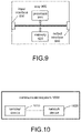
- FIG. 10 is a schematic block diagram of a communication system 1000 provided by an embodiment of the present application. As shown in FIG. 10 , the communication system 1000 includes a terminal device 1010 and a network device 1020.
- the terminal device 1010 may be used to implement the corresponding functions implemented by the UE in the above method, and the network device 1020 may be used to implement the corresponding functions implemented by the network device in the above method. For brevity, details are not repeated here.
- the network device may be one of an access network node and a core network device.
- Embodiments of the present disclosure further provide a computer-readable storage medium for storing a computer program.
- the computer-readable storage medium may be applied to a network device or a terminal device in the embodiments of the present disclosure, and the computer program enables the computer to execute the corresponding processes implemented by the network device in various methods of the embodiments of the present disclosure.
- the computer program enables the computer to execute the corresponding processes implemented by the network device in various methods of the embodiments of the present disclosure.
- Embodiments of the present disclosure further provide a computer program product, including computer program instructions.
- the computer program product may be applied to a network device or a terminal device in the embodiment of the present disclosure, and the computer program instructions enable the computer to execute the corresponding process implemented by the network device in various methods in the embodiment of the present disclosure.
- the computer program instructions enable the computer to execute the corresponding process implemented by the network device in various methods in the embodiment of the present disclosure.
- the embodiment of the present disclosure further provides a computer program.
- the computer program may be applied to the network device or terminal device in the embodiment of the present disclosure, and when the computer program is executed on the computer, the computer is enabled to execute the corresponding processes implemented by the network device in various methods in the embodiment of the present disclosure.
- the computer program may be applied to the network device or terminal device in the embodiment of the present disclosure, and when the computer program is executed on the computer, the computer is enabled to execute the corresponding processes implemented by the network device in various methods in the embodiment of the present disclosure.
- details are not repeated here.
- the disclosed systems, devices and methods may be implemented in other manners.
- the device embodiments described above are only illustrative.
- the categorization of the units is only a categorization of logical function.
- multiple units or components may be combined or can be integrated into another system, or some features can be ignored, or not implemented.
- the shown or discussed mutual coupling or direct coupling or communication connection may be performed through some interfaces, indirect coupling or communication connection of devices or units may be in electrical, mechanical or other forms.
- the units described as separate components may or may not be physically separated, and components displayed as units may or may not be physical units, that is, may be located in one place, or may be distributed to multiple network units. Some or all of the units may be selected according to actual needs to achieve the purpose of the solution in this embodiment.
- each functional unit in various embodiments of the present disclosure may be integrated into one processing unit, or each unit may exist physically alone, or two or more units may be integrated into one unit.
- the functions, if implemented in the form of software functional units and sold or used as independent products, may be stored in a computer-readable storage medium.
- the technical solution of the present disclosure in essence, or the part that contributes to the conventional technology or the part of the technical solution may be embodied in the form of a software product.
- the computer software product is stored in a storage medium, including several instructions that are used to enable a computer device (which may be a personal computer, a server, or a network device, etc.) to execute all or part of the steps of the methods described in the various embodiments of the present disclosure.
- the aforementioned storage medium includes: U disk, mobile hard disk, read-only memory (ROM), random access memory (RAM), magnetic disk or optical disk and other media that can store program codes.
Landscapes
- Engineering & Computer Science (AREA)
- Signal Processing (AREA)
- Computer Networks & Wireless Communication (AREA)
- Mobile Radio Communication Systems (AREA)
Abstract
Description
- The present disclosure relates to the field of communications, and in particular, to a transmission parameter determination method, a terminal device, a network device, a chip, a computer-readable storage medium, a computer program product, and a computer program.
- In the related art, the order and the number of bits of each filed in the downlink control information (DCI) format are determined. In configured grant (CG) transmission, the bits of each domain in the activation and retransmission DCI may be determined by different parameters. Under multiple DCI formats corresponding to different transmission parameter configurations, the number of bits in the same indication field will vary. Therefore, it is necessary to solve the problem of different number of bits of a certain indication field in the DCI corresponding to different transmission parameter set configurations.
- In order to solve the above technical problems, embodiments of the present disclosure provide a transmission parameter determination method, a terminal device, a network device, a chip, a computer-readable storage medium, a computer program product, and a computer program.
- In a first aspect, a transmission parameter determination method is provided, including:
The terminal device receives a first transmission parameter. - The first transmission parameter is used to determine the number of bits of the first indication field in the DCI (downlink control information); a first transmission parameter set and a second transmission parameter set correspond to the first indication field in the DCI.
- In a second aspect, a transmission parameter determination method is provided, including:
- The network device sends the first transmission parameter.
The first transmission parameter is used to determine the number of bits of the first indication field in the DCI; the first transmission parameter and the second transmission parameter correspond to the first indication field in the DCI. - In a third aspect, a terminal device is provided, including:
A first communication unit receives the first transmission parameter. - The first transmission parameter is used to determine the number of bits of the first indication field in the DCI; the first transmission parameter set and the second transmission parameter set correspond to the first indication field in the DCI.
- In a fourth aspect, a network device is provided, including:
A second communication unit sends the first transmission parameter. - The first transmission parameter is used to determine the number of bits of the first indication field in the DCI; the first transmission parameter and the second transmission parameter correspond to the first indication field in the DCI.
- In a fifth aspect, a terminal device is provided, including: a processor and a memory for storing a computer program that can be executed on the processor.
- The memory is used to store a computer program, and the processor is used to invoke and execute the computer program stored in the memory to execute the steps of the method as described above.
- In a sixth aspect, a network device is provided, including: a processor and a memory for storing a computer program that can be executed on the processor.
- The memory is used to store a computer program, and the processor is used to invoke and execute the computer program stored in the memory to execute the steps of the method as described above.
- In a seventh aspect, a chip is provided, including: a processor which is used to invoke and execute a computer program from a memory, so that a device installed with the chip executes the aforementioned method.
- In an eighth aspect, a computer-readable storage medium is provided. The computer-readable storage medium is used for storing a computer program, and the computer program makes a computer to execute the steps of the aforementioned method.
- In a ninth aspect, a computer program product is provided, including computer program instructions, and the computer program instructions make a computer to perform the aforementioned method.
- In a tenth aspect, a computer program is provided. The computer program makes a computer to perform the aforementioned method.
- By adopting the above solution, the first transmission parameter sent by the network device to the terminal device is limited by the second transmission parameter; and the first transmission parameter set and the second transmission parameter set correspond to the first indication field in the DCI. Therefore, the transmission parameters corresponding to the indication field of the same DCI have a constraint relationship, which may solve the problem of different number of bits of a certain indication field in the DCI corresponding to different transmission parameter.
-
-
FIG. 1 is a schematic view 1 of a communication system architecture according to an embodiment of the present disclosure. -
FIG. 2 is a schematic flowchart 1 of a transmission parameter determination method according to an embodiment of the present disclosure. -
FIG. 3 is a schematic flowchart 2 of a transmission parameter determination method according to an embodiment of the present disclosure. -
FIG. 4 is a schematic flowchart 3 of a transmission parameter determination method according to an embodiment of the present disclosure. -
FIG. 5 is a schematic flowchart 4 of a transmission parameter determination method according to an embodiment of the present disclosure. -
FIG. 6 is a schematic structural view of the constituents of a terminal device according to an embodiment of the present disclosure. -
FIG. 7 is a schematic structural view of the constituents of a network device according to an embodiment of the present disclosure. -
FIG. 8 is a schematic structural view of the constituents of a communication device according to an embodiment of the present disclosure. -
FIG. 9 is a schematic block diagram of a chip according to an embodiment of the present disclosure. -
FIG. 10 is a schematic view 2 of a communication system architecture according to an embodiment of the present disclosure. - In order to facilitate comprehensive understanding of the features and technical contents of the embodiments of the present disclosure, the implementation of the embodiments of the present disclosure will be described in detail below with reference to the accompanying drawings. The accompanying drawings are for reference only and are not used to limit the embodiments of the present disclosure.
- The technical solutions in the embodiments of the present disclosure will be described below with reference to the accompanying drawings in the embodiments of the present disclosure. Clearly, the described embodiments are part of the embodiments of the present disclosure, not all of the embodiments. Based on the embodiments in the present disclosure, all other embodiments obtained by those of ordinary skill in the art without creative efforts shall fall within the protection scope of the present disclosure.
- The technical solutions of the embodiments of the present disclosure may be applied to various communication systems, for example: Global System of Mobile communication (GSM) system, LTE Frequency Division Duplex (FDD) system, LTE Time Division Duplex (Time Division Duplex, TDD), 5G communication system or future communication system, etc.
- Exemplarily, a
communication system 100 to which this embodiment of the present disclosure is applied may be as shown inFIG. 1 . Thecommunication system 100 may include anetwork device 110, and thenetwork device 110 may be a device that communicates with the UE 120 (or referred to as a communication terminal device, a terminal device). Thenetwork device 110 may provide communication coverage for a particular geographic area and may communicate with UEs located within the coverage area. Optionally, thenetwork device 110 may be a network device (Base Transceiver Station, BTS) in a GSM system or a CDMA system, or a network device (NodeB, NB) in a WCDMA system, or an evolution network device (Evolutional Node B, eNB or eNodeB) in an LTE system, or a wireless controller in a cloud radio access network (CRAN), or the network device may be a mobile exchange center, a relay station, an access point, a vehicle-mounted device, a wearable device, a hubs, an exchanger, a bridge, a router, a network-side device in 5G network or a network device in a future evolution network, etc. - The
communication system 100 further includes at least one UE 120 located within the coverage of thenetwork device 110. There may be wired communication or wireless communication between the UE 120 and thenetwork device 110. A UE that communicates wirelessly with thenetwork device 110 may be referred to as a "wireless communication terminal device", a "wireless terminal device" or a "mobile terminal device". - It should be understood that the terms "system" and "network" are often used interchangeably herein. The term "and/or" in this disclosure is only an association relational term for describing the relationship between associated objects, indicating that there can be three kinds of relationships, such as A and/or B, which can mean that A exists alone, A and B exist simultaneously, and B exists alone. In addition, the character "/" in this disclosure generally indicates that there is an "or" relationship between the associated objects.
- In order to facilitate comprehensive understanding of the features and technical contents of the embodiments of the present disclosure, the implementation of the embodiments of the present disclosure will be described in detail below with reference to the accompanying drawings. The accompanying drawings are for reference only and are not used to limit the embodiments of the present disclosure.
- An embodiment of the present disclosure provides a transmission parameter determination method, as shown in
FIG. 2 , including:
Step 21: A terminal device receives a first transmission parameter. - The first transmission parameter is used to determine the number of bits of a first indication field in the DCI; the first transmission parameter and the second transmission parameter correspond to the first indication field in the DCI.
- An embodiment of the present disclosure further provides a transmission parameter determination method, as shown in
FIG. 3 , including:
Step 31: A network device sends a first transmission parameter. - The first transmission parameter is used to determine the number of bits of a first indication field in the DCI; a first transmission parameter set and a second transmission parameter set correspond to the first indication field in the DCI.
- In a solution provided by this embodiment, the solution may further include that the terminal device receives the second transmission parameter sent by the network device.
- Specifically, the step may be that the terminal device receives the second transmission parameter set sent by the network device.
- Still further, the terminal device may receive the first transmission parameter set and the second transmission parameter set sent by the network device.
- The first transmission parameter includes: at least one transmission parameter among the transmission parameters of the CG (Configured Grant).
- And/or, the second transmission parameter includes: at least one transmission parameter among uplink data transmission parameters, or at least one transmission parameter agreed by a protocol.
- It should be understood that both the first transmission parameter and the second transmission parameter may include one or more transmission parameters. When the first transmission parameter includes multiple transmission parameters, the first transmission parameter may be referred to as the first transmission parameter set. Similarly, the second transmission parameter may be regarded as the second transmission parameter set when including multiple transmission parameters.
- The first transmission parameter set (or the second transmission parameter set) may be regarded as the configuration parameter. The first transmission parameter set configuration (or the second transmission parameter set configuration) may be regarded as the configuration of the first transmission parameter set, or the configuration of the second transmission parameter set, that is, the value of the configuration parameter. For example, rbg size is the first transmission parameter, and rbg size=3, 3 is the first transmission parameter configuration.
- The uplink data transmission parameter set configuration may be a transmission parameter set configuration of a PUSCH (Physical Uplink Share Channel).
- The number of bits of the first indication field determined based on the first transmission parameter set is not greater than the number of bits of the first indication field determined based on the second transmission parameter set. It may be understood that the first transmission parameter set configuration is limited by the second transmission parameter set configuration. More specifically, the following may be included:
The number of bits of the first indication field determined based on the first transmission parameter set is less than the number of bits of the first indication field determined based on the second transmission parameter set. - Or, the number of bits of the first indication field determined based on the first transmission parameter set is equal to the number of bits of the first indication field determined based on the second transmission parameter set.
- Based on the above description, the present embodiment is described in detail below with reference to examples.
- This example is applicable to all DCI formats used for uplink scheduling and supported by the terminal. The second transmission parameter is a transmission parameter corresponding to the first indication field with the least number of bits in all DCI formats used for uplink scheduling.
- Specifically, the second transmission parameter set configuration is a transmission parameter set configuration of the first indication field corresponding to the least number of bits in all DCI formats used for uplink scheduling.
- Further, in this example, the transmission parameter of the first indication field corresponding to the least number of bits in all DCI formats used for uplink scheduling is interpreted as: the transmission parameter of the first indication field with the least number of bits in all DCI formats used for uplink scheduling, which is used as the second transmission parameter.
- In addition, all DCI formats used for uplink scheduling include at least: a DCI format 0-1 and a DCI format 0-2.
- Or, all DCI formats used for uplink scheduling at least include: a DCI format 0-0, a DCI format 0-1, and a DCI format 0-2.
- For example, the number of bits of the first indication field determined by the first parameter (set) configuration in ConfiguredGrantConfig is less than or equal to the number of bits of the first indication field determined by the related second parameter (set) configuration in PUSCH-Config. The number of bits of the first indication field determined by the second parameter (set) is the minimum value of the number of bits of the first indication field in all DCI formats supported by the terminal (or all DCI formats used for uplink scheduling).
- Take the first indication field as the antenna port field as an example.
- The DMRS configuration parameter for DCI format 0-1 in PUSCH-Config (that is, the aforementioned uplink data transmission parameter), such as dmrs-UplinkForPUSCH-MappingTypeA and dmrs-UplinkForPUSCH-MappingTypeB, is configured to: support multi-port transmission, and has 3 bits according to the antenna port field (which can be regarded as the first indication field in this example) in the configured DCI format 0-1.
- The DMRS configuration parameter for DCI format 0-2 in PUSCH-Config (that is, the aforementioned uplink data transmission parameter), such as dmrs-UplinkForPUSCH-MappingTypeA-DCI format 0-2 and dmrs-UplinkForPUSCH-MappingTypeB-DCI format 0-2, is not configured, that is, has 0 bit according to the antenna port field in the configured DCI format 0-2.
- The antenna port field in DCI format 0-0 in PUSCH-Config (that is, the aforementioned uplink data transmission parameter) does not exist. Or, the antenna port field in DCI format 0-0 agreed by the protocol does not exist.
- The antenna port field in DCI format 0-0 does not exist, and which may be interpreted that this field has 0 bit.
- Since it is limited in this example that the second transmission parameter set configuration is the transmission parameter set configuration of the first indication field corresponding to the least number of bits in all DCI formats used for uplink scheduling, it means that the second transmission parameter set configuration is the transmission parameter set configuration corresponding to DCI format 0-0 or DCI format 0-2.
- Correspondingly, since it is limited in the example that the number of bits of the first indication field determined based on the first transmission parameter set configuration is not greater than the number of bits of the first indication field determined based on the second transmission parameter set configuration, it means that the second transmission parameter set configuration determines that the number of bits of the first indication field is 0, then the bits of the first indication field configured by the first transmission parameter set configuration are also 0. That is to say, it corresponds to the situation that the number of bits of the first indication field determined based on the first transmission parameter set is equal to the number of bits of the first indication field determined based on the second transmission parameter set.
- In combination with the foregoing, for example, the DMRS configuration parameter (that is, the first transmission parameter) in ConfiguredGrantConfig, such as cg-DMRS-Configuration, is limited to all DCI formats, such as the configuration of DCI formats 0-0/0-1/0-2, therefore, cg-DMRS-Configuration is not configured.
- The above description of the first transmission parameter set configuration and the second transmission parameter set configuration is also applicable to the terminal device side and the network device side.
- This example is described with reference to
FIG. 4 , which may include:
Step 41: The terminal device receives the first transmission parameter (set) and the second transmission parameter (set). - For example, the terminal device receives ConfiguredGrantConfig (Configuration of CG) and PUSCH-Config (Physical Uplink Share Channel Configuration). The descriptions related the first transmission parameter set configuration and the second transmission parameter set configuration are the same as those described above, and will not be repeated here.
- Step 42: The terminal device receives the DCI that activates the Configured Grant.
- In this step, the method further includes: determining the number of bits of the first indication field in the DCI for activating the Configured Grant; and the terminal device parses the first indication field according to the first transmission parameter configuration.
- The DCI format for activating the Configured Grant is one of all the DCI formats used for uplink scheduling, or one of all the DCI formats for activating the Configured Grant.
- The first indication field is one of at least one indication field of the DCI for activating the Configured Grant.
- The step of determining the number of bits of the first indication field in the DCI that activates the Configured Grant may be: determining the number of bits of the first indication field according to at least one transmission parameter in the uplink data transmission parameters.
- Further, the step of determining the number of bits of the first indication field in the DCI for activating the Configured Grant may be: determining the number of bits of the first indication field according to at least one transmission parameter in the uplink data transmission parameters corresponding to the DCI format for activating the Configured Grant.
- The first indication field is one of multiple DCI fields included in the DCI that activates the Configured Grant. That is to say, one DCI may contain multiple indication fields, and these indication fields can be respectively interpreted as the first indication field. Different first indication fields may correspond to different second transmission parameter set configurations and first transmission parameter set configurations (on the network device side). However, for different first indication fields, the constraint rules for the related second transmission parameter set configuration and the first transmission parameter set configuration are the same as those described above in this example, so no further description is incorporated herein.
- For example, the DCI that activates the Configured Grant received by the terminal adopts the DCI format 0-1. According to the DMRS configuration parameter for DCI format 0-1 in PUSCH-Config (that is, at least one transmission parameter in the uplink data transmission parameter corresponding to the DCI format that activates the Configured Grant), such as dmrs-UplinkForPUSCH-MappingTypeA and dmrs-UplinkForPUSCH-MappingTypeB, it is determined that the antenna port field (that is, the first indication field) has 3 bits.
- According to the DMRS configuration parameter (the first transmission parameter) in the Configured Grant, such as cg-DMRS-Configuration, it is not configured. The terminal does not interpret the antenna port field. By default, the antenna port is a single port and the port number is 0. Correspondingly, the network device side may determine, according to the first transmission parameter configuration, that no configuration is to be performed in the first indication field in the sent DCI that activates Configured Grant.
- It should also be pointed out that although the above example takes the DMRS port parameter configuration as an example, in actual practice, the first transmission parameter or the second transmission parameter is at least one of the following:
Demodulation reference signal DMRS port related parameters, frequency domain frequency hopping parameters, frequency domain resource parameters, parameters of uplink control information UCI multiplexed to physical uplink share channel PUSCH, and DMRS sequence initialization parameters. - When the first transmission parameter or the second transmission parameter is a parameter set, the first transmission parameter set or the second transmission parameter set is at least one of the following:
Frequency domain frequency hopping parameter set (for example, frequencyHopping), frequency domain resource parameter set (for example, ResourceAllocationTypel-Granularity), parameter set (for example, uci-onPUSCH) of uplink control information (UCI) multiplexed to the physical uplink share channel (PUSCH), DMRS sequence initialization parameter set (for example, DMRSsequenceinitialization), and DMRE port related parameter set. - Certainly, in addition to the parameters listed above, the target transmission parameter configuration set may further include more parameters, which may be set according to actual conditions, and will not be further described here.
- This example applies to all DCI formats used for Configured Grant transmission. The second transmission parameter is a transmission parameter corresponding to the first indication field with the least number of bits in the DCI format used for Configured Grant transmission.
- Specifically, the second transmission parameter set configuration is a transmission parameter set configuration of the first indication field corresponding to the least number of bits in the DCI format used for Configured Grant transmission.
- In this example, the second transmission parameter is the transmission parameter corresponding to the first indication field with the least number of bits in the DCI format used for the Configured Grant transmission, which can be interpreted as: the transmission parameter corresponding to the first indication field with the least number of bits in the DCI format used for Configured Grant transmission is used as the second transmission parameter.
- The DCI used to transmit the Configured Grant may be the DCI used to activate the Configured Grant, or may be the DCI used to retransmit the Configured Grant. In this example, the DCI for activating the Configured Grant is taken as an example for description.
- For example, the number of bits of the first indication field determined by the first parameter (set) in ConfiguredGrantConfig is less than or equal to the number of bits of the first indication field determined by the related second parameter (set) in PUSCH-Config.
- The number of bits of the first indication field determined by the second parameter (set) is the minimum value of the number of bits of the first indication field in all DCI formats used to activate the Configured Grant.
- Take the first indication field as the antenna port field as an example.
- The DMRS configuration parameter for DCI format 0-1 in PUSCH-Config (that is, the aforementioned uplink data transmission parameter), such as dmrs-UplinkForPUSCH-MappingTypeA and dmrs-UplinkForPUSCH-MappingTypeB, is configured to support multi-port transmission, and the antenna port field in DCI format 0-1 having 4 bit is configured according to the DMRS configuration parameter.
- DMRS configuration parameter for DCI format 0-2 in PUSCH-Config (that is, the aforementioned uplink data transmission parameter), such as dmrs-UplinkForPUSCH-MappingTypeA-DCI format 0-2 and dmrs-UplinkForPUSCH-MappingTypeB-DCI format 0-2, is configured to support multi-port transmission, and the antenna port field (that is, the first indication field) having 3 bits in DCI format 0-2 is configured according to the SMRS configuration parameter.
- The default antenna port field in DCI format 0-0 in PUSCH-Config (that is, the aforementioned uplink data transmission parameter) does not exist, or the first indication field of DCI format 0-0 as agreed in the protocol does not exist.
- The pre-configured DCI format 0-1 and DCI format 0-2 are all DCI formats used for Configured Grant transmission, then the second transmission parameter set configuration is the transmission parameter set configuration corresponding to the antenna port field (that is, the first indication field) having 3 bits.
- Correspondingly, the number of bits of the first indication field determined based on the first transmission parameter set configuration is not greater than the number of bits of the first indication field determined based on the second transmission parameter set configuration. That is, when the number of bits of the first indication field determined by the second transmission parameter set configuration is 3, then the bits of the first indication field corresponding to the first transmission parameter set configuration are less than or equal to 3 bits.
- In combination with the foregoing, for example, the DMRS configuration parameter (that is, the first transmission parameter set) in ConfiguredGrantConfig, such as cg-DMRS-Configuration, is limited to all DCI formats used to activate ConfiguredGrant, such as DCI format 0-1/0-2 configuration. Therefore, cg-DMRS-Configuration may also be configured to support multi-port transmission, and the corresponding antenna port field is 3 bits at maximum, and may be less than 3 bits, such as 2 bits, or may be equal to 3 bits. This example adopts 3 bits as an example.
- The above description of the first transmission parameter set configuration and the second transmission parameter set configuration is also applicable to the terminal device side and the network device side.
- The processing flow for this example may be:
- 1. The same as Example 1 and will not be repeated here.
- 2. The terminal device receives the DCI that activates the Configured Grant.
- In this step, the method further includes: determining the number of bits of the first indication field in the DCI for activating the Configured Grant; and the terminal device parses the first indication field according to the first transmission parameter configuration.
- The DCI format for activating the Configured Grant is one of all the DCI formats used for uplink scheduling, or one of all the DCI formats for activating the Configured Grant.
- The first indication field is one of at least one indication field of the DCI for activating the Configured Grant.
- The step of determining the number of bits of the first indication field in the DCI that activates the Configured Grant may be: determining the number of bits of the first indication field according to at least one transmission parameter in the uplink data transmission parameters.
- Further, the step of determining the number of bits of the first indication field in the DCI for activating the Configured Grant may be: determining the number of bits of the first indication field according to at least one transmission parameter in the uplink data transmission parameters corresponding to the DCI format for activating the Configured Grant.
- For example, the DCI that activates the Configured Grant received by the terminal adopts the DCI format 0-1. According to the DMRS configuration parameter for DCI format 0-1 in PUSCH-Config (that is, at least one transmission parameter in the uplink data transmission parameter corresponding to the DCI format that activates the Configured Grant), such as dmrs-UplinkForPUSCH-MappingTypeA and dmrs-UplinkForPUSCH-MappingTypeB, it is determined that the antenna port field has 4 bits.
- Then, according to the DMRS configuration parameter (the first transmission parameter) in the Configured Grant, such as cg-DMRS-Configuration, the terminal device only interprets 3 bits in the antenna port field.
- Correspondingly, the network device side may determine, according to the first transmission parameter configuration, to perform configuration corresponding to 3 bits in the first indication field in the sent DCI that activates the Configured Grant.
- It should also be pointed out that although the above example takes the DMRS port parameter configuration as an example, in actual practice, the first transmission parameter or the second transmission parameter is at least one of the following:
Demodulation reference signal DMRS port related parameters, frequency domain frequency hopping parameters, frequency domain resource parameters, parameters of uplink control information UCI multiplexed to physical uplink shared channel PUSCH, and DMRS sequence initialization parameters. - When the first transmission parameter or the second transmission parameter is a parameter set, the first transmission parameter set or the second transmission parameter set is at least one of the following:
Frequency domain frequency hopping parameter set (for example, frequencyHopping), frequency domain resource parameter set (for example, ResourceAllocationTypel-Granularity), parameter set (for example, uci-onPUSCH) of uplink control information (UCI) multiplexed to the physical uplink share channel (PUSCH), DMRS sequence initialization parameter set (for example, DMRSsequenceinitialization), and DMRE port related parameter set. - Certainly, in addition to the parameters listed above, the target transmission parameter configuration set may further include more parameters, which may be set according to actual conditions, and will not be further described here.
- In this example, the second transmission parameter is the transmission parameter corresponding to the first indication field with the largest number of bits in all DCI formats used for uplink scheduling; or, the second transmission parameter is the transmission parameter corresponding to the first indication field with the largest number of bits in the DCI format used for Configured Grant transmission.
- That is, the number of bits of the first indication field determined by the first parameter (set) in ConfiguredGrantConfig is less than or equal to the number of bits of the first indication field determined by the related second parameter (set) in PUSCH-Config.
- The number of bits of the first indication field determined by the second parameter (set) is the maximum value of the number of bits of the related first indication field in all DCI formats used for Configured Grant transmission. Alternatively, the number of bits of the first indication field determined by the second parameter (set) is the maximum value of the number of bits of the first indication field in all DCI formats used for uplink scheduling.
- The Configured Grant transmission may be used for activating the Configured Grant or scheduled for the Configured Grant retransmission.
- Take the first indication field as the antenna port field as an example.
- The DMRS configuration parameter for DCI format 0-1 in PUSCH-Config (that is, the aforementioned uplink data transmission parameter), such as dmrs-UplinkForPUSCH-MappingTypeA and dmrs-UplinkForPUSCH-MappingTypeB, is configured to support multi-port transmission, and the antenna port field having 4 bits in DCI format 0-1 is configured according to the DMRS configuration parameter. The DMRS configuration parameter for DCI format 0-2, such as dmrs-UplinkForPUSCH-MappingTypeA-DCI format 0-2 and dmrs-UplinkForPUSCH-MappingTypeB-DCI format 0-2, is configured to support multi-port transmission, and the antenna port field having 3 buts in DCI format 0-2 is configured according to the DMRS configuration parameter. The default antenna port field in DCI format 0-0 does not exist.
- In this example, the second transmission parameter set configuration is the maximum value of the number of bits of the relevant first indication field in all DCI formats supported by the terminal device, and the second transmission parameter set configuration may be the DMRS configuration parameter of DCI format 0-1.
- The DMRS configuration parameter (first transmission parameters) in ConfiguredGrantConfig, such as cg-DMRS-Configuration, is limited to all DCI formats. Therefore, cg-DMRS-Configuration may also be configured to support multi-port transmission, and the corresponding antenna port field has 4 bits at maximum. That is to say, the number of bits of the first indication field corresponding to the first transmission parameter may be less than 4 bits, for example, may be 2 bits, or 3 bits, and of course may be equal to 4 bits. In this example, 4 bits are adopted as an example.
- In another example, if the second transmission parameter set configuration is the maximum value of the number of bits of the related first indication field in all DCI formats used to activate the Configured Grant, then the second transmission parameter set configuration may be DMRS configuration parameter of DCI format 0-1.
- Correspondingly, the DMRS configuration parameter (first transmission parameter set) in ConfiguredGrantConfig, such as cg-DMRS-Configuration, is limited to all DCI formats used to activate ConfiguredGrant, such as the configuration of DCI format 0-1/0-2. Therefore, cg-DMRS-Configuration may also be configured to support multi-port transmission, and the corresponding antenna port field has 4 bits at maximum.
- Description is provided with reference to
FIG. 5 : - Step 51: The terminal receives ConfiguredGrantConfig and PUSCH-Config.
- Step 52: The terminal receives the DCI that activates the Configured Grant, determines the corresponding transmission parameter set configuration according to the DCI DCI format that activates the Configured Grant, and parses the DCI that activates the Configured Grant.
- The processing of this step is described in detail in several conditions.
- Condition 1: In a case that the DCI for activating the Configured Grant is the third DCI format, parsing the first indication field according to the first transmission parameter.
- The third DCI format is DCI format 0-1.
- Correspondingly, the network device configures the first indication field according to the first transmission parameter in a case that the DCI to be sent for activating the Configured Grant is the third DCI format.
- The method may further include: in a case that the DCI for activating the Configured Grant is the third DCI format, the number of bits of the first indication field is determined according to the second transmission parameter, and paraing the first indication field according to the first transmission parameter.
- For example, if the DCI that activates the Configured Grant received by the terminal adopts DCI format 0-1, according to the DMRS configuration parameter (second transmission parameter) for DCI format 0-1 in PUSCH-Config, such as dmrs-UplinkForPUSCH-MappingTypeA and dmrs-UplinkForPUSCH- MappingTypeB, it is determined that the antenna port field has 4 bits.
- According to the DMRS configuration parameter (the first transmission parameter) in the Configured Grant, such as cg-DMRS-Configuration, the 4 bits in the antenna port field are parsed.
- Condition 2: In the case that the DCI that activates the Configured Grant is the fourth DCI format, parsing the first indication field according to the first transmission parameter.
- In the case that the DCI for activating the Configured Grant is the fourth DCI format, parsing the first indication field according to the second transmission parameter; or,
- In the case that the DCI for activating the Configured Grant is the fourth DCI format, parsing the first indication field according to the first transmission parameter and the second transmission parameter.
- The fourth DCI format is DCI 0-2.
- The method may also include: in the case that the DCI for activating the Configured Grant is the third DCI format, the number of bits of the first indication field is determined according to the second transmission parameter set configuration, and parsing the first indication field according to the first transmission parameter set configuration and/or parsing the first indication field according to the second transmission parameter set configuration.
- For example, if the DCI that activates the Configured Grant received by the terminal adopts DCI format 0-2, according to the DMRS configuration parameter (second transmission parameter) for DCI format 0-2 in PUSCH-Config, such as dmrs-UplinkForPUSCH-MappingTypeA-DCIformat0-2 and dmrs-UplinkForPUSCH-MappingTypeB-DCIformat0-2, it is determined that the antenna port field has 3 bits.
- Going a step further:
Condition 2.1: The terminal parses the 3 bits in the antenna port field, and determines the information indicated by the antenna port according to the DMRS configuration parameter (the first transmission parameter) in the Configured Grant, such as cg-DMRS-Configuration. - There may be conditions where the bits of the first indication field determined according to the first transmission parameter set configuration are greater than the number of bits of the first indication field determined by the second transmission parameter set configuration, that is:
- In a case that the DCI for activating the Configured Grant is the fourth DCI format, if the number of bits of the first indication field determined according to the second transmission parameter set configuration is less than the number of bits of the first indication field determined according to the first transmission parameter set configuration, then the first indication field corresponds to the part of the value corresponding to the first transmission parameter set configuration.
- For example, cg-DMRS-Configuration determines that the antenna port supports 16 configurations, namely {0, 1, 2, 3, 4, 5, 6, 7, 0-1, 2-3, 4-5, 6-7, 0-3, 4-7,0-5, 0-7}, but since the antenna port field has only 3 bits, it only corresponds to the first 8 configurations in the configuration, or corresponds to the single-port configuration in the configuration.
- Condition 2.2: The terminal parses the 3 bits in the antenna port field, and determines the information indicated by the antenna port (the first indication field) according to the DMRS configuration parameter (second transmission parameter) for DCI format 0-2 in PUSCH-Config, such as dmrs-UplinkForPUSCH-MappingTypeA-DCIformat0-2 and dmrs-UplinkForPUSCH-MappingTypeB-DCIformat0-2. Correspondingly, the network device may configure the information indicated by the first indication field according to the second transmission parameter set configuration.
- Condition 2.3: Terminal (or network device) can perform the following:
According to the DMRS configuration parameter (second transmission parameter) for DCI format 0-2 in PUSCH-Config, such as dmrs-UplinkForPUSCH-MappingTypeA-DCIformat0-2 and dmrs-UplinkForPUSCH-MappingTypeB-DCIformat0-2, and the first transmission parameter, such as cg-DMRS-Configuration, jointly determines the information indicated by the antenna port. - In another example, the FDRA field (which can be interpreted as the first indication field) in DCI format 0-2 may be jointly determined according to resource allocation and/or rbg (which can be interpreted as the first transmission parameter) in ConfiguredgrantConfig and ResourceAllocationType1-Granularity (which may be interpreted as the second transmission parameter) in PUSCHConfig.
- In condition 3, the second transmission parameter is a transmission parameter corresponding to the first indication field of the first DCI format, and the first DCI format is one of all the DCI formats used for uplink scheduling.
- This situation is applicable to the scenario where the DCI format is specified, that is, the second transmission parameter (set) is the transmission parameter corresponding to the first indication field of the specified first DCI format.
- The first DCI format is agreed by the protocol or configured by the network. That is, the specified first DCI format is specified by the protocol, for example, in some cases, only the first DCI format can be used for transmission; alternatively, it may be that the network device specifies only the first DCI format is adopted for transmission at a certain occasion (or within a certain period of time).
- The first DCI format is DCI format 0-1. Of course, the first DCI format may also be other formats, as long as it is a specified format determined according to a protocol agreement or network device configuration, for example, the first DCI format may be DCI formats 0-2, etc., no further description is provided herein.
- In this condition, the second transmission parameter may be used for determining the number of bits of the first indication field in the DCI; then, the first indication field may be parsed through the first transmission parameter set configuration. Alternatively, the protocol stipulates that the second transmission parameter set configuration is used to parse the first indication field.
- For example, the DMRS configuration parameter (second transmission parameter) for DCI format 0-1 in PUSCH-Config, such as dmrs-UplinkForPUSCH-MappingTypeA and dmrs-UplinkForPUSCH-MappingTypeB, is configured to support multi-port transmission, and the antenna port field (the first indication field) having 4 bits in the DCI format 0-1 is configured according to the DMRS configuration parameter.
- Then, the 4 bits in the antenna port field may be interpreted (or configured) according to the second transmission parameter set configuration (or the first transmission parameter).
- In condition 4, the second transmission parameter is a transmission parameter corresponding to the first indication field of the second DCI format, and the second DCI format is one of all the DCI formats used for Configured Grant transmission.
- The only difference between this condition and condition 3 is that the second DCI format is one of all DCI formats used for the Configured Grant transmission. Specifically, the second DCI format may also be agreed by a protocol or configured by a network. The second DCI format is DCI format 0-1. Of course, the second DCI format may also be other formats, as long as it is a specified format determined according to a protocol agreement or network device configuration, for example, the second DCI format may be DCI format 0-2, etc., and no further description is not incorporated herein.
- The same parts as described in condition 3 will not be repeated here.
- The foregoing examples mainly focus on the processing of the DCI for activating the Configured Grant, and this example describes the related processing of the DCI for retransmitting the Configured Grant.
- The network device sends the DCI that retransmits the Configured Grant; correspondingly, the terminal device receives the DCI that retransmits the Configured Grant.
- The DCI format for retransmitting the Configured Grant is consistent with the DCI format for activating the Configured Grant.
- The DCI format for activating the Configured Grant needs to be consistent with the scheduling DCI format for retransmitting the Configured Grant.
- For example, the terminal receives the first DCI sent by the network device to activate the Configured Grant, and the first DCI is the first DCI format.
- The terminal receives the second DCI sent by the network device for scheduling retransmission of the Configured Grant, and the second DCI is the second DCI format. The second DCI format is the same as the first DCI format.
- Technical advantages: The initial transmission and retransmission of the Configured Grant can maintain a consistent transmission configuration and reduce the complexity of the terminal.
- Correspondingly, the processing method for the DCI configured for retransmitting the Configured Grant may be the same as the foregoing example, and details are not repeated here.
- The network device sends the DCI that retransmits the Configured Grant; correspondingly, the terminal device receives the DCI that retransmits the Configured Grant.
- The DCI format configured for retransmitting the Configured Grant is independent of the DCI format configured for activating the Configured Grant.
- The DCI format for activating the Configured Grant may be inconsistent with the scheduling DCI format for retransmitting the Configured Grant.
- The terminal receives the first DCI for activating the Configured Grant, and the first DCI is the first DCI format.
- The terminal receives the second DCI for scheduling the retransmission of the Configured Grant, and the second DCI is a second DCI format. The second DCI format is independently configured from the first DCI format, and they may be the same or different.
- The content of the first indication field in the DCI for retransmitting the Configured Grant is parsed by using the same first transmission parameter set configuration as the DCI format that activates the Configured Grant; or, the content of the first indication field in the DCI for retransmitting the Configured Grant is parsed by adopting the first transmission parameter set configuration corresponding to the DCI for retransmitting the Configured Grant.
- The specific parsing method is not repeated in this example.
- Finally, it should be pointed out that (the configuration of) the first transmission parameter in this example is limited by (the configuration of) the second transmission parameter, and may be applicable to all transmission parameters.
- Alternatively, the above condition may be applicable to some parameters, for example, the first transmission parameter or the second transmission parameter is at least one of the following:
Demodulation reference signal DMRS port related parameters, frequency domain frequency hopping parameters, frequency domain resource parameters, parameters of uplink control information UCI multiplexed to physical uplink share channel PUSCH, and DMRS sequence initialization parameters. - When the first transmission parameter or the second transmission parameter is a parameter set, the first transmission parameter set or the second transmission parameter set is at least one of the following:
Frequency domain frequency hopping parameter set (for example, frequencyHopping), frequency domain resource parameter set (for example, ResourceAllocationTypel-Granularity), parameter set (for example, uci-onPUSCH) of uplink control information (UCI) multiplexed to the physical uplink share channel (PUSCH), DMRS sequence initialization parameter set (for example, DMRSsequenceinitialization), and DMRE port related parameter set. - It may be obtained that by adopting the above solution, the first transmission parameter set configuration sent by the network device to the terminal device is limited by the second transmission parameter set configuration; and the first transmission parameter set and the second transmission parameter set correspond to the first indication field in the DCI. Therefore, the transmission parameter set configuration corresponding to the indication field of the same DCI has a constraint relationship. In this manner, it is possible to solve the problem of different number of bits of a certain indication field in the DCI corresponding to different transmission parameter set configurations.
- An embodiment of the present disclosure provides a terminal device, as shown in
FIG. 6 , including:
A first communication unit 61 receives the first transmission parameter set configuration. - The first transmission parameter is configured to determine the number of bits of the first indication field in the DCI; the first transmission parameter set and the second transmission parameter set correspond to the first indication field in the DCI.
- An embodiment of the present disclosure further provides a transmission network device, as shown in
FIG. 7 , including:
Asecond communication unit 71 receives the first transmission parameter set configuration. - The first transmission parameter is configured to determine the number of bits of the first indication field in the DCI; the first transmission parameter set and the second transmission parameter set correspond to the first indication field in the DCI.
- The first transmission parameter includes: at least one transmission parameter in the transmission parameters of the Configured Grant.
- And/or, the second transmission parameter includes: at least one transmission parameter in the uplink data transmission parameters, or at least one transmission parameter agreed by a protocol.
- It should be understood that both the first transmission parameter and the second transmission parameter may include one or more transmission parameters. When the first transmission parameter includes multiple transmission parameters, the first transmission parameter may be referred to as the first transmission parameter set. Similarly, the second transmission parameter may be regarded as the second transmission parameter set when including multiple transmission parameters.
- The number of bits of the first indication field determined based on the first transmission parameter set is not greater than the number of bits of the first indication field determined based on the second transmission parameter set. It can be interpreted that the first transmission parameter set configuration is limited by the second transmission parameter set configuration. More specifically, the following may be included:
The number of bits of the first indication field determined based on the first transmission parameter set is less than the number of bits of the first indication field determined based on the second transmission parameter set. - Alternatively, the number of bits of the first indication field determined based on the first transmission parameter set is equal to the number of bits of the first indication field determined based on the second transmission parameter set.
- Based on the above description, the present embodiment is described in detail below with reference to examples.
- This example is applicable to all DCI formats supported by the terminal and can be used for uplink scheduling. The second transmission parameter is a transmission parameter corresponding to the first indication field with the least number of bits in all DCI formats used for uplink scheduling.
- Specifically, the second transmission parameter set configuration is a transmission parameter set configuration of the first indication field corresponding to the least number of bits in all DCI formats used for uplink scheduling.
- Further, in this example, the transmission parameters of the first indication field corresponding to the least number of bits in all DCI formats used for uplink scheduling are interpreted as: the transmission parameter with the least number of bits in the first indication field in all DCI formats used for uplink scheduling is used as the second transmission parameter.
- The first transmission parameter set may be composed of at least one transmission parameter in the transmission parameters of the Configured Grant. The second transmission parameter set may be composed of at least one transmission parameter in the uplink data transmission parameters, or composed of at least one transmission parameter agreed in the protocol.
- In addition, all DCI formats used for uplink scheduling include at least: DCI format 0-1 and DCI format 0-2.
- Or, all DCI formats used for uplink scheduling at least include: DCI format 0-0, DCI format 0-1, and DCI format 0-2.
- The first communication unit of the terminal device receives the first transmission parameter set configuration and the second transmission parameter set configuration.
- For example, the terminal device receives ConfiguredGrantConfig and PUSCH-Config (Physical Uplink Share Channel Configuration). The relevant descriptions about the first transmission parameter set configuration and the second transmission parameter set configuration are the same as those described above, and will not be repeated here.
- The first communication unit of the terminal device receives the DCI that activates the Configured Grant.
- The
first processing unit 62 further included in the terminal device determines the number of bits of the first indication field in the DCI that activates the Configured Grant. Thefirst processing unit 62 of the terminal device parses the first indication field according to the first transmission parameter configuration. - The DCI format for activating the Configured Grant is one of all the DCI formats used for uplink scheduling, or one of all the DCI formats for activating the Configured Grant.
- The first indication field is one of at least one indication field of the DCI for activating the Configured Grant.
- The
first processing unit 62 of the terminal device determines the number of bits of the first indication field according to at least one transmission parameter in the uplink data transmission parameters. In addition, the network device may further include asecond processing unit 72, which determines the number of bits of the first indication field according to at least one transmission parameter in the uplink data transmission parameters. - The first indication field is one of multiple DCI fields included in the DCI that activates the Configured Grant. That is to say, one DCI may contain multiple indication fields, and these indication fields can be respectively regarded as the first indication field. Different first indication fields may correspond to different second transmission parameter set configurations and first transmission parameter set configurations (on the network device side). However, for different first indication fields, the constraint rules for the related second transmission parameter set configurations and the first transmission parameter set configurations are the same as those described above in this example, so no further details are repeated here.
- It should be pointed out that although the above example takes the DMRS port parameter configuration as an example, in actual practice, the first transmission parameter or the second transmission parameter is at least one of the following:
Demodulation reference signal DMRS port related parameters, frequency domain frequency hopping parameters, frequency domain resource parameters, parameters of uplink control information UCI multiplexed to physical uplink share channel PUSCH, and DMRS sequence initialization parameters. - When the first transmission parameter or the second transmission parameter is a parameter set, the first transmission parameter set or the second transmission parameter set is at least one of the following:
Frequency domain frequency hopping parameter set (for example, frequencyHopping), frequency domain resource parameter set (for example, ResourceAllocationTypel-Granularity), parameter set (for example, uci-onPUSCH) of uplink control information (UCI) multiplexed to the physical uplink share channel (PUSCH), DMRS sequence initialization parameter set (for example, DMRSsequenceinitialization), and DMRE port related parameter set. - Certainly, in addition to the parameters listed above, the target transmission parameter set configuration may further include more parameters, which may be set according to actual conditions, and no further details are incorporated here.
- This example applies to all DCI formats used for Configured Grant transmission. The second transmission parameter is a transmission parameter corresponding to the first indication field with the least number of bits in the DCI format used for Configured Grant transmission.
- Specifically, the second transmission parameter set configuration is a transmission parameter set configuration of the first indication field corresponding to the least number of bits in the DCI format used for the Configured Grant transmission.
- In this example, the second transmission parameter is the transmission parameter corresponding to the first indication field with the least number of bits in the DCI format used for the Configured Grant transmission, which may be interpreted as: the transmission parameter corresponding to the least number of bits corresponding to the first indication field in the DCI format used for Configured Grant transmission is used as the second transmission parameter.
- The first transmission parameter set may be composed of at least one transmission parameter in the transmission parameters of the Configured Grant. The second transmission parameter set may be composed of at least one transmission parameter in the uplink data transmission parameters, or composed of at least one transmission parameter agreed in the protocol.
- The number of bits of the first indication field determined by the second parameter (set) is the minimum value of the number of bits of the first indication field in all DCI formats used to activate the Configured Grant.
- The first communication unit 61 of the terminal device receives the first transmission parameter set configuration and the second transmission parameter set configuration.
- The first communication unit 61 of the terminal device receives the DCI that activates the Configured Grant.
- The
first processing unit 62 of the terminal device determines the number of bits of the first indication field in the DCI that activates the Configured Grant; the terminal device parses the first indication field according to the first transmission parameter configuration. - The DCI format for activating the Configured Grant is one of all the DCI formats used for uplink scheduling, or one of all the DCI formats for activating the Configured Grant.
- The first indication field is one of at least one indication field of the DCI for activating the Configured Grant.
- The
first processing unit 62 of the terminal device or thesecond processing unit 72 of the network device determines the number of bits of the first indication field according to at least one transmission parameter in the uplink data transmission parameters. - In this example, the second transmission parameter is the transmission parameter corresponding to the first indication field with the largest number of bits in all DCI formats used for uplink scheduling. Alternatively, the second transmission parameter is the transmission parameter corresponding to the first indication field with the largest number of bits in the DCI format used for Configured Grant transmission.
- The number of bits of the first indication field determined by the second parameter (set) is the maximum value of the number of bits of the first indication field in all DCI formats used for Configured Grant transmission. Alternatively, the number of bits of the first indication field determined by the second parameter (set) may be used for the maximum value of the number of bits of the first indication field in all DCI formats used for uplink scheduling.
- The Configured Grant transmission may be scheduled for activating the Configured Grant or the Configured Grant retransmission.
- The first communication unit 61 of the terminal device receives the DCI that activates the Configured Grant, and the
first processing unit 62 of the terminal device determines a corresponding transmission parameter set configuration according to the DCI format of the DCI that activates the Configured Grant, and parses the DCI that activates the Configured Grant. - The processing of this step is described in detail in several conditions.
- Condition 1: The
first processing unit 62 of the terminal device parses the first indication field according to the first transmission parameter set configuration in a case that the DCI for activating the Configured Grant is the third DCI format. - The third DCI format is DCI format 0-1.
- Correspondingly, the second processing unit of the network device configures the first indication field according to the first transmission parameter set configuration in the case that the DCI to be sent to activate the Configured Grant is the third DCI format.
- The condition may further include: in the case that the DCI for activating the Configured Grant is the third DCI format, determining the number of bits of the first indication field according to the second transmission parameter, and parsing the first indication field according to the first transmission parameter.
- Condition 2: The
first processing unit 62 of the terminal device parses the first indication field according to the first transmission parameter in a case that the DCI for activating the Configured Grant is the fourth DCI format. - In the case that the DCI for activating the Configured Grant is the fourth DCI format, parsing the first indication field according to the second transmission parameter; or,
- In the case that the DCI for activating the Configured Grant is the fourth DCI format, parsing the first indication field according to the first transmission parameter and the second transmission parameter.
- The fourth DCI format is DCI 0-2.
- Furthermore:
- In a case that the DCI for activating the Configured Grant is the fourth DCI format, if the
first processing unit 62 of the terminal device determines that, according to the second transmission parameter, the number of bits of the first indication field is less than the number of bits of the first indication field determined according to the first transmission parameter set configuration, then the first indication field corresponds to part of the value corresponding to the first transmission parameter. - Condition 2.2: The terminal parses the 3 bits in the antenna port field, and configures parameters (second transmission parameters) according to the DMRS for DCI format 0-2 in PUSCH-Config, such as dmrs-UplinkForPUSCH-MappingTypeA-DCIformat0-2 and dmrs-UplinkForPUSCH-MappingTypeB-DCIformat0-2, thus determining the information indicated by the antenna port.
- Condition 2.3: The terminal parses the 3 bits in the antenna port field, and configures parameters (second transmission parameters) according to the DMRS for DCI format 0-2 in PUSCH-Config, such as dmrs-UplinkForPUSCH-MappingTypeA-DCIformat0-2 and dmrs-UplinkForPUSCH-MappingTypeB-DCIformat0-2, and the first transmission parameter set configuration, such as cg-DMRS-Configuration, thus jointly determining the information indicated by the antenna port.
- In condition 3, the second transmission parameter set configuration is a transmission parameter set configuration corresponding to the first indication field of the first DCI format, and the first DCI format is one of all the DCI formats used for uplink scheduling.
- This situation is applicable to the scenario where the DCI format is specified, that is, the second transmission parameter set configuration is the transmission parameter set configuration corresponding to the first indication field of the specified first DCI format.
- The first DCI format is agreed by the protocol or configured by the network. That is, the specified first DCI format is specified by the protocol, for example, in some cases, only the first DCI format can be used for transmission; or, it may be that the network device specifies that only the first DCI format is used for transmission at a certain occasion (or within a certain period of time).
- The first DCI format is DCI format 0-1.
- In this condition, the second transmission parameter may be used to determine the number of bits of the first indication field in the DCI. Then, the first indication field may be parsed through the first transmission parameter, or the protocol stipulates that the second transmission parameter is used to parse the first indication field.
- In condition 4, the second transmission parameter set configuration is a transmission parameter corresponding to the first indication field in the second DCI format, and the second DCI format is one of all DCI formats used for the Configured Grant transmission.
- The only difference between the above condition and condition 3 is that the second DCI format is one of all DCI formats used for the Configured Grant transmission. Specifically, the second DCI format may also be agreed by a protocol or configured by a network. The second DCI format is DCI format 0-1. Other details will not be repeated here.
- The foregoing examples mainly focus on the processing of activating the DCI of the Configured Grant, and this example describes the related processing of retransmitting the DCI of the Configured Grant.
- The network device sends the DCI that retransmits the Configured Grant; correspondingly, the terminal device receives the DCI that retransmits the Configured Grant.
- The DCI format for retransmitting Configured Grant is consistent with the DCI format for activating the Configured Grant.
- The DCI format for activating the Configured Grant needs to be consistent with the scheduling DCI format for retransmitting the Configured Grant.
- For example, the terminal receives the first DCI sent by the network device to activate the Configured Grant, and the first DCI is in the first DCI format.
- The terminal receives the second DCI sent by the network device for scheduling retransmission of the Configured Grant, and the second DCI is in the second DCI format. The second DCI format is the same as the first DCI format.
- Technical advantages: The initial transmission and retransmission of the Configured Grant can maintain a consistent transmission configuration and reduce the complexity of the terminal.
- Correspondingly, the processing method for retransmitting the DCI of the Configured Grant may be the same as the foregoing example, and details are not repeated here.
- The network device sends the DCI that retransmits the Configured Grant; correspondingly, the terminal device receives the DCI that retransmits the Configured Grant.
- The DCI format for retransmitting the Configured Grant is independent of the DCI format for activating the Configured Grant.
- The DCI format for activating the Configured Grant may be inconsistent with the scheduling DCI format for retransmitting the Configured Grant.
- The terminal receives the first DCI for activating Configured Grant, and the first DCI is the first DCI format.
- The terminal receives the second DCI for scheduling the retransmission of the Configured Grant, and the second DCI is a second DCI format. The second DCI format is independently configured from the first DCI format, and they may be the same as or different from each other.
- The content of the first indication field in the DCI of the retransmitted Configured Grant is parsed by using the first transmission parameter set configuration which is the same as the DCI format that activates the Configured Grant; or, the content of the first indication field in the DCI for retransmitting Configured Grant is parsed by using the first transmission parameter set configuration corresponding to the DCI for retransmitting the Configured Grant.
- The specific parsing method is not repeated in this example.
- Finally, it should be pointed out that the first transmission parameter set configuration in this example is limited to the second transmission parameter set configuration, and may be applicable to all transmission parameters.
- Alternatively, the first transmission parameter or the second transmission parameter is at least one of the following:
Demodulation reference signal DMRS port related parameters, frequency domain frequency hopping parameters, frequency domain resource parameters, parameters of uplink control information UCI multiplexed to physical uplink share channel PUSCH, and DMRS sequence initialization parameters. - When the first transmission parameter or the second transmission parameter is a parameter set, the first transmission parameter set or the second transmission parameter set is at least one of the following:
Frequency domain frequency hopping parameter set (for example, frequencyHopping), frequency domain resource parameter set (for example, ResourceAllocationType1-Granularity), parameter set (for example, uci-onPUSCH) of uplink control information (UCI) multiplexed to the physical uplink share channel (PUSCH), DMRS sequence initialization parameter set (for example, DMRSsequenceinitialization), and DMRE port related parameter set. - It may be obtained that by adopting the above solution, the first transmission parameter set configuration sent by the network device to the terminal device is limited by the second transmission parameter set configuration; and the first transmission parameter set and the second transmission parameter set correspond to the first indication field in the DCI. Therefore, the transmission parameter set configuration corresponding to the indication field of the same DCI has a constraint relationship. In this manner, it is possible to solve the problem of different number of bits of a certain indication field in the DCI corresponding to different transmission parameter set configurations.
-
FIG. 8 is a schematic structural view of acommunication device 800 according to an embodiment of the present disclosure. The communication device in this embodiment may be specifically one of a terminal device and a network device in the foregoing embodiments. Thecommunication device 800 shown inFIG. 8 includes aprocessor 810, and theprocessor 810 may invoke and execute a computer program from a memory to implement the method in the embodiment of the present disclosure. - Optionally, as shown in
FIG. 8 , thecommunication device 800 may further include amemory 820. Theprocessor 810 may invoke and execute a computer program from thememory 820 to implement the method in the embodiment of the present disclosure. - The
memory 820 may be a separate device independent of theprocessor 810, or may be integrated in theprocessor 810. - Optionally, as shown in
FIG. 8 , thecommunication device 800 may further include atransceiver 830, and theprocessor 810 may control thetransceiver 830 to communicate with other devices, specifically, may send information or data to other devices, or receive information or data sent by other devices. - The
transceiver 830 may include a transmitter and a receiver. Thetransceiver 830 may further include antennas, and the number of the antennas may be one or more. - Optionally, the
communication device 800 may specifically be a network device in this embodiment of the present disclosure, and thecommunication device 800 may implement the corresponding processes implemented by the network device in various methods in the embodiment of the present disclosure. For brevity, details are not repeated here. - Optionally, the
communication device 800 may specifically be a terminal device or a network device in the embodiment of the present disclosure, and thecommunication device 800 may implement the corresponding processes implemented by the mobile terminal/terminal device in various methods of the embodiment of the present disclosure. For brevity, details are not repeated here. - For example, the first processing unit of the above terminal device may be implemented by the
processor 810 in thecommunication device 800; or, the second processing unit of the network device may be implemented by theprocessor 810 in thecommunication device 800. - The first communication unit of the above terminal device may be implemented by the
transceiver 830 in thecommunication device 800; or, the second communication unit of the network device may be implemented by thetransceiver 830 of thecommunication device 800. -
FIG. 9 is a schematic structural view of a chip according to an embodiment of the present disclosure. Thechip 900 shown inFIG. 9 includes aprocessor 910, and theprocessor 910 may invoke and execute a computer program from a memory to implement the method in the embodiment of the present disclosure. - Optionally, as shown in
FIG. 9 , thechip 900 may further include amemory 920. Theprocessor 910 may invoke and execute a computer program from thememory 920 to implement the method in the embodiment of the present disclosure. - The
memory 920 may be a separate device independent of theprocessor 910, or may be integrated in theprocessor 910. - Optionally, the
chip 900 may further include aninput interface 930. Theprocessor 910 may control theinput interface 930 to communicate with other devices or chips, and specifically, may acquire information or data sent by other devices or chips. - Optionally, the
chip 900 may further include anoutput interface 940. Theprocessor 910 may control theoutput interface 940 to communicate with other devices or chips, and specifically, may output information or data to other devices or chips. - Optionally, the chip may be applied to one of a terminal device, an access network node, and a core network device in the embodiment of the present disclosure, and the chip may implement the corresponding processes implemented by the terminal device in various methods of the embodiment of the present disclosure. For brevity, details are not repeated here.
- It should be understood that the chip mentioned in the embodiments of the present disclosure may also be referred to as a system-on-chip, a SoC, a system-level integration, or a SLI, or the like.
- It should be understood that the processor in this embodiment of the present disclosure may be an integrated circuit chip, which has the capability of processing signals. In the implementation process, various steps of the above method embodiments may be completed by an integrated logic circuit in the form of hardware in a processor or an instruction in the form of software. The above-mentioned processor may be a general-purpose processor, a digital signal processor (DSP), an application specific integrated circuit (ASIC), a field programmable gate array (FPGA) or other programmable logic devices, discrete gate or transistor logic devices, and discrete hardware components. Various methods, steps, and logical block diagrams disclosed in the embodiments of the present may can be implemented or executed. A general-purpose processor may be a microprocessor or the processor may be any conventional processor or the like. The steps of the method disclosed in conjunction with the embodiments of the present disclosure may be directly embodied as executed by a hardware decoding processor, or executed by a combination of hardware and software modules in the decoding processor. The software module may be located in random access memory, flash memory, read-only memory, programmable read-only memory or electrically erasable programmable memory, registers and other storage media that are well developed in the field. The storage medium is located in the memory, and the processor reads the information in the memory, and completes the steps of the above method in combination with the hardware thereof.
- It can be understood that the memory in the embodiment of the present disclosure may be a volatile memory or a non-volatile memory, or may include both volatile and non-volatile memory. The non-volatile memory may be Read-Only Memory (ROM), Programmable Read-Only Memory (PROM), Erasable Programmable Read-Only Memory (EPROM), Electrically Erasable Programmable Read-Only Memory (EPROM), or flash memory. Volatile memory may be Random Access Memory (RAM), which serves as an external cache. By way of example and not limitation, many forms of RAM are available, such as Static RAM (SRAM), Dynamic RAM (DRAM), Synchronous DRAM (SDRAM), Double Data Rate SDRAM (DDR SDRAM), Enhanced SDRAM (ESDRAM), Synchlink DRAM (SLDRAM) ) and Direct Rambus RAM (DR RAM). It should be noted that the memory of the systems and methods described herein is intended to include, but not be limited to, these and any other suitable types of memory.
- It should be understood that the above-mentioned memory is an example only and not limited thereto. For example, the memory in this embodiment of the present disclosure may also be a static random access memory (static RAM, SRAM), a dynamic random access memory (dynamic RAM, DRAM), synchronous dynamic random access memory (synchronous DRAM, SDRAM), double data rate SDRAM (DDR SDRAM), enhanced synchronous dynamic random access memory (enhanced SDRAM, ESDRAM), synch link DRAM (SLDRAM) and Direct Rambus RAM (DR RAM) and so on. That is, memory in embodiments of the present disclosure is intended to include, but not be limited to, these and any other suitable types of memory.
-
FIG. 10 is a schematic block diagram of acommunication system 1000 provided by an embodiment of the present application. As shown inFIG. 10 , thecommunication system 1000 includes aterminal device 1010 and anetwork device 1020. - The
terminal device 1010 may be used to implement the corresponding functions implemented by the UE in the above method, and thenetwork device 1020 may be used to implement the corresponding functions implemented by the network device in the above method. For brevity, details are not repeated here. The network device may be one of an access network node and a core network device. - Embodiments of the present disclosure further provide a computer-readable storage medium for storing a computer program.
- Optionally, the computer-readable storage medium may be applied to a network device or a terminal device in the embodiments of the present disclosure, and the computer program enables the computer to execute the corresponding processes implemented by the network device in various methods of the embodiments of the present disclosure. For brevity, details are not repeated here.
- Embodiments of the present disclosure further provide a computer program product, including computer program instructions.
- Optionally, the computer program product may be applied to a network device or a terminal device in the embodiment of the present disclosure, and the computer program instructions enable the computer to execute the corresponding process implemented by the network device in various methods in the embodiment of the present disclosure. For brevity, details are not repeated here.
- The embodiment of the present disclosure further provides a computer program.
- Optionally, the computer program may be applied to the network device or terminal device in the embodiment of the present disclosure, and when the computer program is executed on the computer, the computer is enabled to execute the corresponding processes implemented by the network device in various methods in the embodiment of the present disclosure. For brevity, details are not repeated here.
- Those of ordinary skill in the art can realize that the units and algorithm steps of each example described in conjunction with the embodiments disclosed herein can be implemented in electronic hardware, or a combination of computer software and electronic hardware. Whether these functions are performed in hardware or software depends on the specific application and design constraints of the technical solution. Skilled practitioners may implement the described functionality by using different methods for each particular application, but such implementations should not be considered beyond the scope of the present disclosure.
- Those skilled in the art can clearly understand that, for the convenience and brevity of description, the specific operation process of the system, device and unit described above may refer to the corresponding process in the foregoing method embodiments, and details will not be repeated here.
- In the several embodiments provided by the present disclosure, it should be understood that the disclosed systems, devices and methods may be implemented in other manners. For example, the device embodiments described above are only illustrative. For example, the categorization of the units is only a categorization of logical function. In actual implementation, there may be other categorization methods. For example, multiple units or components may be combined or can be integrated into another system, or some features can be ignored, or not implemented. On the other hand, the shown or discussed mutual coupling or direct coupling or communication connection may be performed through some interfaces, indirect coupling or communication connection of devices or units may be in electrical, mechanical or other forms.
- The units described as separate components may or may not be physically separated, and components displayed as units may or may not be physical units, that is, may be located in one place, or may be distributed to multiple network units. Some or all of the units may be selected according to actual needs to achieve the purpose of the solution in this embodiment.
- In addition, each functional unit in various embodiments of the present disclosure may be integrated into one processing unit, or each unit may exist physically alone, or two or more units may be integrated into one unit.
- The functions, if implemented in the form of software functional units and sold or used as independent products, may be stored in a computer-readable storage medium. Based on such understanding, the technical solution of the present disclosure in essence, or the part that contributes to the conventional technology or the part of the technical solution may be embodied in the form of a software product. The computer software product is stored in a storage medium, including several instructions that are used to enable a computer device (which may be a personal computer, a server, or a network device, etc.) to execute all or part of the steps of the methods described in the various embodiments of the present disclosure. The aforementioned storage medium includes: U disk, mobile hard disk, read-only memory (ROM), random access memory (RAM), magnetic disk or optical disk and other media that can store program codes.
- The above are only specific embodiments of the present disclosure, but the scope to be protected by the present disclosure is not limited thereto. Any person skilled in the art can easily think of changes or substitutions within the technical scope disclosed by the present disclosure, and the changes or substitutions should fall within the scope to be protected by the present disclosure. Therefore, the scope to be protected by the present disclosure should be based on the scope to be protected by the claims.
Claims (73)
- A transmission parameter determination method, comprising:receiving, by a terminal device, a first transmission parameter;wherein the first transmission parameter is used for determining a number of bits of a first indication field in a DCI (downlink control information; the first transmission parameter and a second transmission parameter corresponding to the first indication field in the DCI.
- The method according to claim 1, wherein the number of bits of the first indication field determined based on the first transmission parameter is not greater than the number of bits of the first indication field determined based on the second transmission parameter.
- The method according to claim 1 or 2, wherein the first transmission parameter comprises: at least one transmission parameter among transmission parameters of Configured Grant;
and/or,
a second transmission parameter comprising: at least one transmission parameter among uplink data transmission parameters, or at least one transmission parameter agreed by a protocol. - The method according to any one of claims 1-3, whereinthe second transmission parameter is a transmission parameter corresponding to the first indication field with the least number of bits in all DCI formatsused for uplink scheduling; or,the second transmission parameter is a transmission parameter corresponding to the first indication field with the least number of bits in a DCI format used for Configured Grant transmission; or,the second transmission parameter is a transmission parameter corresponding to the first indication field with the largest number of bits in all the DCI formats used for uplink scheduling; or,the second transmission parameter is a transmission parameter corresponding to the first indication field with the largest number of bits in the DCI format used for the Configured Grant transmission; or,the second transmission parameter is a transmission parameter corresponding to the first indication field of a first DCI format, and the first DCI format is one of all the DCI formats used for uplink scheduling; orthe second transmission parameter is a transmission parameter corresponding to the first indication field of a second DCI format, and the second DCI format is one of all the DCI formats used for the Configured Grant transmission.
- The method according to claim 4, wherein the first DCI format or the second DCI format is agreed by the protocol or configured by a network.
- The method according to claim 4 or 5, wherein the first DCI format or the second DCI format is a DCI format 0-1.
- The method according to claim 4, wherein all the DCI formats used for uplink scheduling comprise at least: a DCI format 0-1 and a DCI format 0-2;
or, all the DCI formats used for uplink scheduling at least comprise: a DCI format 0-0, the DCI format 0-1, and the DCI format 0-2. - The method according to any one of claims 3-7, wherein the method further comprises:
receiving, by the terminal device, a DCI that activates the Configured Grant. - The method according to claim 8, wherein,a DCI format for activating the Configured Grant is one of all the DCI formats used for uplink scheduling, or one of all the DCI formats for activating the Configured Grant;the first indication field is one of at least one indication field of the DCI for activating the Configured Grant.
- The method according to claim 9, wherein the method further comprises:
in a case that the DCI for activating the Configured Grant is a third DCI format, parsing the first indication field according to the first transmission parameter. - The method according to claim 9, wherein the method further comprises:in a case that the DCI that activates the Configured Grant is a fourth DCI format, parsing the first indication field according to the first transmission parameter;
or,in the case that the DCI for activating the Configured Grant is the fourth DCI format, parsing the first indication field according to the second transmission parameter; orin the case that the DCI for activating the Configured Grant is the fourth DCI format, parsing the first indication field according to the first transmission parameter and the second transmission parameter. - The method according to claim 11, wherein in the case that the DCI for activating the Configured Grant is the fourth DCI format, parsing the first indication field according to the first transmission parameter set configuration further comprises:
in the case that the DCI for activating the Configured Grant is the fourth DCI format, and the number of bits of the first indication field determined according to the second transmission parameter is less than the number of bits of the first indication field determined according to the first transmission parameter, then the first indication field corresponds to part of a value corresponding to the first transmission parameter. - The method according to claim 10 or 11, wherein the third DCI format is the DCI format 0-1, and/or the fourth DCI format is the DCI 0-2.
- The method according to claim 8, wherein the method further comprises:receiving, by the terminal device, the DCI that retransmits the Configured Grant;wherein a DCI format that retransmits the Configured Grant is consistent with a DCI format that activates the Configured Grant.
- The method according to claim 8, wherein the method further comprises:receiving, by the terminal device, a DCI that retransmits the Configured Grant;wherein a DCI format for retransmitting the Configured Grant is independent of a DCI format for activating the Configured Grant.
- The method according to claim 15, wherein a content of the first indication field in the DCI for retransmitting the Configured Grant is parsed by using the first transmission parameter which is the same as the DCI format that activates the Configured Grant;
or, the content of the first indication field in the DCI for retransmitting the Configured Grant is parsed by using the first transmission parameter corresponding to the DCI for retransmitting the Configured Grant. - The method according to any one of claims 1-16, wherein the first transmission parameter or the second transmission parameter is at least one of the following:
demodulation reference signal DMRS port related parameters, frequency domain frequency hopping parameters, frequency domain resource parameters, parameters of uplink control information UCI multiplexed to physical uplink share channel PUSCH, and DMRS sequence initialization parameters. - A transmission parameter determination method, comprising:sending, by a network device, a first transmission parameter;wherein the first transmission parameter is used for determining a number of bits of a first indication field in a DCI; the first transmission parameter and a second transmission parameter corresponding to the first indication field in the DCI.
- The method according to claim 18, wherein the number of bits of the first indication field determined based on the first transmission parameter is not greater than the number of bits of the first indication field determined based on the second transmission parameter.
- The method according to claim 18, wherein,the first transmission parameter comprises: at least one transmission parameter among transmission parameters of Configured Grant;and/or,the second transmission parameter comprising: one transmission parameter among uplink data transmission parameters, or one transmission parameter agreed by a protocol.
- The method according to any one of claims 8-20, wherein,the second transmission parameter is a transmission parameter corresponding to the first indication field with the least number of bits in all DCI formats used for uplink scheduling; orthe second transmission parameter is a transmission parameter corresponding to the first indication field with the least number of bits in a DCI format used for Configured Grant transmission; or,the second transmission parameter is a transmission parameter corresponding to the first indication field with the largest number of bits in all the DCI formats used for uplink scheduling; orthe second transmission parameter is a transmission parameter corresponding to the first indication field with the largest number of bits in the DCI format used for the Configured Grant transmission; or,the second transmission parameter is a first DCI format, and the first DCI format is one of all the DCI formats used for uplink scheduling; orthe second transmission parameter is a second DCI format, and the second DCI format is one of all the DCI formats used for the Configured Grant transmission.
- The method according to claim 21, wherein the first DCI format or the second DCI format is agreed by the protocol or configured by a network.
- The method according to claim 21 or 22, wherein the first DCI format or the second DCI format is a DCI format 0-1.
- The method according to claim 21, wherein all the DCI formats used for uplink scheduling comprise at least: a DCI format 0-1 and a DCI format 0-2;
or, all the DCI formats used for uplink scheduling at least comprise: a DCI format 0-0, the DCI format 0-1, and the DCI format 0-2. - The method according to any one of claims 18-24, wherein the method further comprises:
sending, by the network device, a DCI that activates the Configured Grant. - The method according to claim 25, wherein the method further comprises:
in a case that the DCI for activating the Configured Grant is a third DCI format, configuring the first indication field according to the first transmission parameter. - The method according to claim 25, wherein the method further comprises:in a case that the DCI that activates the Configured Grant is a fourth DCI format, configuring the first indication field according to the first transmission parameter;
or,in the case that the DCI for activating the Configured Grant is the fourth DCI format, configuring the first indication field according to the second transmission parameter; orin the case that the DCI for activating the Configured Grant is the fourth DCI format, configuring the first indication field according to the first transmission parameter and the second transmission parameter. - The method according to claim 27, wherein in a case that the DCI for activating the Configured Grant is the second DCI format, configuring the first indication field according to the first transmission parameter further comprises:
in the case that the DCI for activating the Configured Grant is the fourth DCI format, and the number of bits of the first indication field determined according to the second transmission parameter is greater than the number of bits of the first indication field determined according to the first transmission parameter, then the first indication field contains part of a value corresponding to the second transmission parameter. - The method according to claim 26 or 27, wherein the third DCI format is the DCI format 0-1, and/or the fourth DCI format is the DCI 0-2.
- The method according to claim 25, wherein the method further comprises:sending, by the network device, the DCI that retransmits the Configured Grant;wherein a DCI format that retransmits the Configured Grant is consistent with a DCI format that activates the Configured Grant.
- The method according to claim 25, wherein the method further comprises:sending, by the network device, a DCI that retransmits the Configured Grant;wherein a DCI format for retransmitting the Configured Grant is inconsistent with a DCI format for activating the Configured Grant.
- The method according to claim 31, wherein a content of the first indication field in the DCI for retransmitting the Configured Grant is configured by using the first transmission parameter which is the same as the DCI format that activates the Configured Grant;
or, the content of the first indication field in the DCI for retransmitting the Configured Grant is configured by using the first transmission parameter corresponding to the DCI for retransmitting the Configured Grant. - The method according to any one of claims 18-32, wherein the first transmission parameter or the second transmission parameter is at least one of the following:
demodulation reference signal DMRS port related parameters, frequency domain frequency hopping parameters, frequency domain resource parameters, parameters of uplink control information UCI multiplexed to physical uplink share channel PUSCH, and DMRS sequence initialization parameters. - A terminal device, comprising:a first communication unit receiving a first transmission parameter;wherein the first transmission parameter is used for determining a number of bits of a first indication field in a DCI; a first transmission parameter set and a second transmission parameter set correspond to the first indication field in the DCI.
- The terminal device according to claim 34, wherein the number of bits of the first indication field determined based on the first transmission parameter set is not greater than the number of bits of the first indication field determined based on the second transmission parameter set.
- The terminal device according to claim 34 or 35, wherein the first transmission parameter comprises: at least one transmission parameter among transmission parameters of Configured Grant;
and/or,
a second transmission parameter comprising: at least one transmission parameter among uplink data transmission parameters, or at least one transmission parameter agreed by a protocol. - The terminal device according to any one of claims 34-36, wherein,the second transmission parameter is a transmission parameter corresponding to the first indication field with the least number of bits in all DCI formats used for uplink scheduling; or,the second transmission parameter is a transmission parameter corresponding to the first indication field with the least number of bits in a DCI format used for Configured Grant transmission; or,the second transmission parameter is a transmission parameter corresponding to the first indication field with the largest number of bits in all the DCI formats used for uplink scheduling; or,the second transmission parameter is a transmission parameter corresponding to the first indication field with the largest number of bits in the DCI format used for the Configured Grant transmission; or,the second transmission parameter is a transmission parameter corresponding to the first indication field of a first DCI format, and the first DCI format is one of all the DCI formats used for uplink scheduling; orthe second transmission parameter is a transmission parameter corresponding to the first indication field of a second DCI format, and the second DCI format is one of all the DCI formats used for the Configured Grant transmission.
- The terminal device according to claim 37, wherein the first DCI format or the second DCI format is agreed by the protocol or configured by a network.
- The terminal device according to claim 37 or 38, wherein the first DCI format or the second DCI format is a DCI format 0-1.
- The terminal device according to claim 37, wherein all the DCI formats used for uplink scheduling comprise at least: a DCI format 0-1 and a DCI format 0-2;
or, all the DCI formats used for uplink scheduling at least comprise: a DCI format 0-0, the DCI format 0-1, and the DCI format 0-2. - The terminal device according to any one of claims 36-40, wherein the first communication unit receives a DCI that activates the Configured Grant.
- The terminal device according to claim 41, wherein,a DCI format for activating the Configured Grant is one of all the DCI formats used for uplink scheduling, or one of all the DCI formats for activating the Configured Grant;the first indication field is one of at least one indication field of the DCI for activating the Configured Grant.
- The terminal device according to claim 42, wherein the terminal device further comprises:
a first processing unit, parsing the first indication field according to the first transmission parameter in a case that the DCI for activating the Configured Grant is a third DCI format. - The terminal device according to claim 42, wherein the terminal device further comprises:a first processing unit, parsing the first indication field according to the first transmission parameter in a case that the DCI for activating the Configured Grant is a fourth DCI format;
or,parsing the first indication field according to the second transmission parameter in the case that the DCI for activating the Configured Grant is the fourth DCI format; or,parsing the first indication field according to the first transmission parameter and the second transmission parameter in the case that the DCI for activating the Configured Grant is the fourth DCI format. - The terminal device according to claim 44, wherein in the case that the DCI for activating the Configured Grant is the fourth DCI format, if the first processing unit determines that, according to the second transmission parameter, the number of bits of the first indication field is less than the number of bits of the first indication field determined according to the first transmission parameter, then the first indication field corresponds to part of a value corresponding to the first transmission parameter.
- The terminal device according to claim 41 or 42, wherein the third DCI format is the DCI format 0-1, and/or the fourth DCI format is the DCI 0-2.
- The terminal device according to claim 41, wherein the first communication unit receives a DCI that retransmits the Configured Grant;
wherein a DCI format that retransmits the Configured Grant is consistent with a DCI format that activates the Configured Grant. - The terminal device according to claim 41, wherein the first communication unit receives a DCI that retransmits the Configured Grant;
wherein a DCI format for retransmitting the Configured Grant is independent of a DCI format for activating the Configured Grant. - The terminal device according to claim 48, wherein a content of the first indication field in the DCI for retransmitting the Configured Grant is parsed by using the first transmission parameter which is the same as the DCI format that activates the Configured Grant;
or, the content of the first indication field in the DCI for retransmitting the Configured Grant is parsed by using the first transmission parameter corresponding to the DCI for retransmitting the Configured Grant. - The terminal device according to any one of claims 34-39, wherein the first transmission parameter or the second transmission parameter is at least one of the following:
demodulation reference signal DMRS port related parameters, frequency domain frequency hopping parameters, frequency domain resource parameters, parameters of uplink control information UCI multiplexed to physical uplink share channel PUSCH, and DMRS sequence initialization parameters. - A network device, comprising:a second communication unit sending a first transmission parameter;wherein the first transmission parameter is used for determining a number of bits of a first indication field in a DCI; the first transmission parameter and a second transmission parameter corresponding to the first indication field in the DCI.
- The network device according to claim 51, wherein the number of bits of the first indication field determined based on the first transmission parameter is not greater than the number of bits of the first indication field determined based on the second transmission parameter.
- The network device according to claim 51, wherein,the first transmission parameter comprises: a transmission parameter among transmission parameters of Configured Grant;
and/or,the second transmission parameter comprising: a transmission parameter among uplink data transmission parameters, or a transmission parameter agreed by a protocol. - The network device according to any one of claims 51-53, wherein,the second transmission parameter is a transmission parameter corresponding to the first indication field with the least number of bits in all DCI formats used for uplink scheduling; orthe second transmission parameter is a transmission parameter corresponding to the first indication field with the least number of bits in a DCI format used for Configured Grant transmission; orthe second transmission parameter is a transmission parameter corresponding to the first indication field with the largest number of bits in all the DCI formats used for uplink scheduling; orthe second transmission parameter is a transmission parameter corresponding to the first indication field with the largest number of bits in the DCI format used for the Configured Grant transmission; orthe second transmission parameter is in a first DCI format, and the first DCI format is one of all the DCI formats used for uplink scheduling; orthe second transmission parameter is in a second DCI format, and the second DCI format is one of all the DCI formats used for Configured Grant transmission.
- The network device according to claim 54, wherein the first DCI format or the second DCI format is agreed by the protocol or configured by a network.
- The network device according to claim 54 or 55, wherein the first DCI format or the second DCI format is a DCI format 0-1.
- The network device according to claim 54, wherein all the DCI formats used for uplink scheduling comprise at least: a DCI format 0-1 and a DCI format 0-2;
or, all the DCI formats used for uplink scheduling at least comprise: a DCI format 0-0, the DCI format 0-1, and the DCI format 0-2. - The network device according to any one of claims 51-57, wherein the second communication unit sends a DCI that activates the Configured Grant.
- The network device according to claim 58, wherein the network device further comprises:
a second processing unit, configuring the first indication field according to the first transmission parameter in a case that the DCI for activating the Configured Grant is a third DCI format. - The network device according to claim 58, wherein the network device further comprises:a second processing unit, configuring the first indication field according to the first transmission parameter in a case that the DCI for activating the Configured Grant is a fourth DCI format;
or,configuring the first indication field according to the second transmission parameter in the case that the DCI for activating the Configured Grant is the fourth DCI format; or,configuring the first indication field according to the first transmission parameter and the second transmission parameter in the case that the DCI for activating the Configured Grant is the fourth DCI format. - The network device according to claim 60, wherein in the case that the DCI for activating the Configured Grant is the fourth DCI format, if the second processing unit determines that, according to the second transmission parameter, the number of bits of the first indication field is greater than the number of bits of the first indication field determined according to the first transmission parameter, then the first indication field contains part of a value corresponding to the second transmission parameter.
- The network device according to claim 60 or 61, wherein the third DCI format is the DCI format 0-1, and/or the fourth DCI format is the DCI 0-2.
- The network device according to claim 58, wherein the second communication unit sends a DCI that retransmits the Configured Grant;
wherein a DCI format that retransmits the Configured Grant is consistent with a DCI format that activates the Configured Grant. - The network device according to claim 58, wherein the second communication unit sends a DCI that retransmits the Configured Grant;
wherein a DCI format for retransmitting the Configured Grant is inconsistent with a DCI format for activating the Configured Grant. - The network device according to claim 64, wherein a content of the first indication field in the DCI for retransmitting the Configured Grant is configured by using the first transmission parameter which is the same as the DCI format that activates the Configured Grant;
or, the content of the first indication field in the DCI for retransmitting the Configured Grant is configured by using the first transmission parameter corresponding to the DCI for retransmitting the Configured Grant. - The network device according to any one of claims 51-65, wherein the first transmission parameter or the second transmission parameter is at least one of the following:
demodulation reference signal DMRS port related parameters, frequency domain frequency hopping parameters, frequency domain resource parameters, parameters of uplink control information UCI multiplexed to physical uplink share channel PUSCH, and DMRS sequence initialization parameters. - A terminal device, comprising: a processor and a memory for storing a computer program that can be executed on the processor,
wherein the memory is used for storing a computer program, and the processor is used for invoking and execute the computer program stored in the memory to execute the steps of the method claimed in any one of claims 1-17. - A network device, comprising: a processor and a memory for storing a computer program that can be executed on the processor,
wherein the memory is used for storing a computer program, and the processor is used for invoking and execute the computer program stored in the memory to execute the steps of the method claimed in any one of claims 18-33. - A chip, comprising: a processor which is used for invoking and execute a computer program from a memory, so that a device installed with the chip executes the method claimed in any one of claims 1-17.
- A chip, comprising: a processor which is used for invoking and execute a computer program from a memory, so that a device installed with the chip executes the method claimed in any one of claims 18-33.
- A computer-readable storage medium, wherein the computer-readable storage medium is adopted for storing a computer program, and the computer program makes a computer to execute the steps of the method claimed in any one of claims 1-33.
- A computer program product, comprising computer program instructions, wherein the computer program instructions make a computer to perform the method claimed in any one of claims 1-33.
- A computer program, wherein the computer program makes a computer to perform the method claimed in any one of claims 1-33.
Applications Claiming Priority (1)
| Application Number | Priority Date | Filing Date | Title |
|---|---|---|---|
| PCT/CN2020/075407 WO2021159517A1 (en) | 2020-02-14 | 2020-02-14 | Transmission parameter determination method, terminal device, and network device |
Publications (2)
| Publication Number | Publication Date |
|---|---|
| EP4102754A1 true EP4102754A1 (en) | 2022-12-14 |
| EP4102754A4 EP4102754A4 (en) | 2023-03-22 |
Family
ID=77292737
Family Applications (1)
| Application Number | Title | Priority Date | Filing Date |
|---|---|---|---|
| EP20918563.6A Pending EP4102754A4 (en) | 2020-02-14 | 2020-02-14 | PROCEDURE FOR DETERMINING TRANSMISSION PARAMETERS, TERMINAL AND NETWORK DEVICE |
Country Status (4)
| Country | Link |
|---|---|
| US (1) | US12279275B2 (en) |
| EP (1) | EP4102754A4 (en) |
| CN (1) | CN114747170A (en) |
| WO (1) | WO2021159517A1 (en) |
Families Citing this family (3)
| Publication number | Priority date | Publication date | Assignee | Title |
|---|---|---|---|---|
| CN113677008B (en) * | 2020-05-15 | 2025-09-02 | 华为技术有限公司 | Communication method, device and storage medium |
| CN116094667B (en) * | 2021-11-03 | 2025-12-05 | 维沃移动通信有限公司 | Transmission parameter determination method, resource determination method, equipment and storage medium |
| US20260089688A1 (en) * | 2024-09-25 | 2026-03-26 | Qualcomm Incorporated | Demodulation reference signal parameter selection for grant-free user equipment uplink transmission |
Family Cites Families (5)
| Publication number | Priority date | Publication date | Assignee | Title |
|---|---|---|---|---|
| EP4184835A1 (en) * | 2018-05-11 | 2023-05-24 | LG Electronics, Inc. | Method of performing uplink transmission in wireless communication system and device therefor |
| US11457434B2 (en) * | 2018-06-22 | 2022-09-27 | Sharp Laboratories Of America, Inc. | User equipments, base stations and methods for time-domain resource allocation |
| US20200022144A1 (en) * | 2018-07-09 | 2020-01-16 | Samsung Electronics Co., Ltd. | Overhead reduction and reliability enhancements for dl control signaling |
| JP7230060B2 (en) * | 2018-11-01 | 2023-02-28 | 株式会社Nttドコモ | Terminal, wireless communication method, base station and system |
| CN110536399B (en) * | 2019-09-03 | 2024-10-15 | 中兴通讯股份有限公司 | Power control method, device and system |
-
2020
- 2020-02-14 EP EP20918563.6A patent/EP4102754A4/en active Pending
- 2020-02-14 CN CN202080081391.8A patent/CN114747170A/en active Pending
- 2020-02-14 WO PCT/CN2020/075407 patent/WO2021159517A1/en not_active Ceased
-
2022
- 2022-08-12 US US17/886,459 patent/US12279275B2/en active Active
Also Published As
| Publication number | Publication date |
|---|---|
| EP4102754A4 (en) | 2023-03-22 |
| CN114747170A (en) | 2022-07-12 |
| US20220386360A1 (en) | 2022-12-01 |
| US12279275B2 (en) | 2025-04-15 |
| WO2021159517A1 (en) | 2021-08-19 |
Similar Documents
| Publication | Publication Date | Title |
|---|---|---|
| US11855925B2 (en) | Uplink control information sending and receiving method and apparatus | |
| US12095542B2 (en) | Methods and devices for determining spatial relation, user equipment and network device | |
| US12279275B2 (en) | Transmission parameter determination method, terminal device, and network device | |
| CN112970294B (en) | Signal transmission method, terminal equipment and network equipment | |
| CN111769919B (en) | Sounding Reference Signal SRS Transmission Method and Communication Device | |
| WO2022241658A1 (en) | Half-duplex data transmission method, terminal device and network device | |
| US20160242038A1 (en) | BACKHAUL SIGNALING SUPPORT FOR UL-DL INTERFERENCE MANAGEMENT FOR TDD eIMTA | |
| WO2021026836A1 (en) | Communication method and communication apparatus | |
| WO2019137221A1 (en) | Uplink data transmission method and device | |
| AU2019438207B2 (en) | Method for transmitting data and terminal device | |
| WO2020030047A1 (en) | Communication method and related device | |
| CN116235444A (en) | Wireless communication method, terminal device and network device | |
| US20240267179A1 (en) | User equipment, scheduling node, method for user equipment, and method for scheduling node | |
| US20240365243A1 (en) | Communication method and apparatus | |
| AU2019303771A1 (en) | D2d communication method and terminal device | |
| WO2018076326A1 (en) | Communication method and apparatus for uplink carrier aggregation | |
| WO2021013017A1 (en) | Method and device for scell beam failure recovery, ue and network device | |
| EP3051905A1 (en) | Mobile communication method and radio base station | |
| US20250062876A1 (en) | Communication method, device, storage medium, and chip | |
| US20250081125A1 (en) | Communication method and apparatus, storage medium, and program product | |
| WO2020200115A1 (en) | Communication method, apparatus and system, and storage medium | |
| CN114287118B (en) | Downlink control signaling receiving method, network equipment and terminal equipment | |
| EP4381826A1 (en) | Transmitting a mac ce message by an iab node | |
| US11184864B2 (en) | Method for wireless communication, terminal device, network device, and network node | |
| US20240334448A1 (en) | Method and apparatus for determining unified transmission configuration indication in network cooperative communication |
Legal Events
| Date | Code | Title | Description |
|---|---|---|---|
| STAA | Information on the status of an ep patent application or granted ep patent |
Free format text: STATUS: THE INTERNATIONAL PUBLICATION HAS BEEN MADE |
|
| PUAI | Public reference made under article 153(3) epc to a published international application that has entered the european phase |
Free format text: ORIGINAL CODE: 0009012 |
|
| STAA | Information on the status of an ep patent application or granted ep patent |
Free format text: STATUS: REQUEST FOR EXAMINATION WAS MADE |
|
| 17P | Request for examination filed |
Effective date: 20220909 |
|
| AK | Designated contracting states |
Kind code of ref document: A1 Designated state(s): AL AT BE BG CH CY CZ DE DK EE ES FI FR GB GR HR HU IE IS IT LI LT LU LV MC MK MT NL NO PL PT RO RS SE SI SK SM TR |
|
| REG | Reference to a national code |
Ref country code: DE Ref legal event code: R079 Free format text: PREVIOUS MAIN CLASS: H04L0005000000 Ipc: H04W0072040000 |
|
| A4 | Supplementary search report drawn up and despatched |
Effective date: 20230220 |
|
| RIC1 | Information provided on ipc code assigned before grant |
Ipc: H04L 5/00 20060101ALI20230214BHEP Ipc: H04W 72/23 20230101ALI20230214BHEP Ipc: H04W 72/04 20090101AFI20230214BHEP |
|
| DAV | Request for validation of the european patent (deleted) | ||
| DAX | Request for extension of the european patent (deleted) | ||
| STAA | Information on the status of an ep patent application or granted ep patent |
Free format text: STATUS: EXAMINATION IS IN PROGRESS |
|
| 17Q | First examination report despatched |
Effective date: 20250527 |