EP4102714A1 - Power conversion system for dispersed power source - Google Patents
Power conversion system for dispersed power source Download PDFInfo
- Publication number
- EP4102714A1 EP4102714A1 EP20917907.6A EP20917907A EP4102714A1 EP 4102714 A1 EP4102714 A1 EP 4102714A1 EP 20917907 A EP20917907 A EP 20917907A EP 4102714 A1 EP4102714 A1 EP 4102714A1
- Authority
- EP
- European Patent Office
- Prior art keywords
- power
- power inverter
- testing
- inverter used
- inverter
- Prior art date
- Legal status (The legal status is an assumption and is not a legal conclusion. Google has not performed a legal analysis and makes no representation as to the accuracy of the status listed.)
- Pending
Links
Images


Classifications
-
- H—ELECTRICITY
- H02—GENERATION; CONVERSION OR DISTRIBUTION OF ELECTRIC POWER
- H02J—ELECTRIC POWER NETWORKS; CIRCUIT ARRANGEMENTS OR SYSTEMS FOR SUPPLYING OR DISTRIBUTING ELECTRIC POWER; SYSTEMS FOR STORING ELECTRIC ENERGY
- H02J3/00—Circuit arrangements for AC mains or AC distribution networks
- H02J3/38—Arrangements for feeding a single network from two or more generators or sources in parallel; Arrangements for feeding already energised networks from additional generators or sources in parallel
-
- H—ELECTRICITY
- H02—GENERATION; CONVERSION OR DISTRIBUTION OF ELECTRIC POWER
- H02M—APPARATUS FOR CONVERSION BETWEEN AC AND AC, BETWEEN AC AND DC, OR BETWEEN DC AND DC, AND FOR USE WITH MAINS OR SIMILAR POWER SUPPLY SYSTEMS; CONVERSION OF DC OR AC INPUT POWER INTO SURGE OUTPUT POWER; CONTROL OR REGULATION THEREOF
- H02M1/00—Details of apparatus for conversion
- H02M1/10—Arrangements incorporating converting means for enabling loads to be operated at will from different kinds of power supplies, e.g. from AC or DC
-
- G—PHYSICS
- G01—MEASURING; TESTING
- G01R—MEASURING ELECTRIC VARIABLES; MEASURING MAGNETIC VARIABLES
- G01R31/00—Arrangements for testing electric properties; Arrangements for locating electric faults; Arrangements for electrical testing characterised by what is being tested not provided for elsewhere
- G01R31/40—Testing power supplies
-
- H—ELECTRICITY
- H02—GENERATION; CONVERSION OR DISTRIBUTION OF ELECTRIC POWER
- H02J—ELECTRIC POWER NETWORKS; CIRCUIT ARRANGEMENTS OR SYSTEMS FOR SUPPLYING OR DISTRIBUTING ELECTRIC POWER; SYSTEMS FOR STORING ELECTRIC ENERGY
- H02J3/00—Circuit arrangements for AC mains or AC distribution networks
- H02J3/28—Arrangements for balancing of the load in networks by storage of energy
- H02J3/32—Arrangements for balancing of the load in networks by storage of energy using batteries or super capacitors with converting means
-
- H—ELECTRICITY
- H02—GENERATION; CONVERSION OR DISTRIBUTION OF ELECTRIC POWER
- H02J—ELECTRIC POWER NETWORKS; CIRCUIT ARRANGEMENTS OR SYSTEMS FOR SUPPLYING OR DISTRIBUTING ELECTRIC POWER; SYSTEMS FOR STORING ELECTRIC ENERGY
- H02J3/00—Circuit arrangements for AC mains or AC distribution networks
- H02J3/38—Arrangements for feeding a single network from two or more generators or sources in parallel; Arrangements for feeding already energised networks from additional generators or sources in parallel
- H02J3/381—Dispersed generators
-
- H—ELECTRICITY
- H02—GENERATION; CONVERSION OR DISTRIBUTION OF ELECTRIC POWER
- H02M—APPARATUS FOR CONVERSION BETWEEN AC AND AC, BETWEEN AC AND DC, OR BETWEEN DC AND DC, AND FOR USE WITH MAINS OR SIMILAR POWER SUPPLY SYSTEMS; CONVERSION OF DC OR AC INPUT POWER INTO SURGE OUTPUT POWER; CONTROL OR REGULATION THEREOF
- H02M1/00—Details of apparatus for conversion
- H02M1/32—Means for protecting converters other than automatic disconnection
-
- H—ELECTRICITY
- H02—GENERATION; CONVERSION OR DISTRIBUTION OF ELECTRIC POWER
- H02M—APPARATUS FOR CONVERSION BETWEEN AC AND AC, BETWEEN AC AND DC, OR BETWEEN DC AND DC, AND FOR USE WITH MAINS OR SIMILAR POWER SUPPLY SYSTEMS; CONVERSION OF DC OR AC INPUT POWER INTO SURGE OUTPUT POWER; CONTROL OR REGULATION THEREOF
- H02M7/00—Conversion of AC power input into DC power output; Conversion of DC power input into AC power output
- H02M7/42—Conversion of DC power input into AC power output without possibility of reversal
- H02M7/44—Conversion of DC power input into AC power output without possibility of reversal by static converters
- H02M7/48—Conversion of DC power input into AC power output without possibility of reversal by static converters using discharge tubes with control electrode or semiconductor devices with control electrode
-
- H—ELECTRICITY
- H02—GENERATION; CONVERSION OR DISTRIBUTION OF ELECTRIC POWER
- H02M—APPARATUS FOR CONVERSION BETWEEN AC AND AC, BETWEEN AC AND DC, OR BETWEEN DC AND DC, AND FOR USE WITH MAINS OR SIMILAR POWER SUPPLY SYSTEMS; CONVERSION OF DC OR AC INPUT POWER INTO SURGE OUTPUT POWER; CONTROL OR REGULATION THEREOF
- H02M7/00—Conversion of AC power input into DC power output; Conversion of DC power input into AC power output
- H02M7/42—Conversion of DC power input into AC power output without possibility of reversal
- H02M7/44—Conversion of DC power input into AC power output without possibility of reversal by static converters
- H02M7/48—Conversion of DC power input into AC power output without possibility of reversal by static converters using discharge tubes with control electrode or semiconductor devices with control electrode
- H02M7/493—Conversion of DC power input into AC power output without possibility of reversal by static converters using discharge tubes with control electrode or semiconductor devices with control electrode the static converters being arranged for operation in parallel
-
- H—ELECTRICITY
- H02—GENERATION; CONVERSION OR DISTRIBUTION OF ELECTRIC POWER
- H02J—ELECTRIC POWER NETWORKS; CIRCUIT ARRANGEMENTS OR SYSTEMS FOR SUPPLYING OR DISTRIBUTING ELECTRIC POWER; SYSTEMS FOR STORING ELECTRIC ENERGY
- H02J2101/00—Supply or distribution of decentralised, dispersed or local electric power generation
- H02J2101/20—Dispersed power generation using renewable energy sources
- H02J2101/22—Solar energy
- H02J2101/24—Photovoltaics
-
- Y—GENERAL TAGGING OF NEW TECHNOLOGICAL DEVELOPMENTS; GENERAL TAGGING OF CROSS-SECTIONAL TECHNOLOGIES SPANNING OVER SEVERAL SECTIONS OF THE IPC; TECHNICAL SUBJECTS COVERED BY FORMER USPC CROSS-REFERENCE ART COLLECTIONS [XRACs] AND DIGESTS
- Y02—TECHNOLOGIES OR APPLICATIONS FOR MITIGATION OR ADAPTATION AGAINST CLIMATE CHANGE
- Y02E—REDUCTION OF GREENHOUSE GAS [GHG] EMISSIONS, RELATED TO ENERGY GENERATION, TRANSMISSION OR DISTRIBUTION
- Y02E10/00—Energy generation through renewable energy sources
- Y02E10/50—Photovoltaic [PV] energy
- Y02E10/56—Power conversion systems, e.g. maximum power point trackers
Definitions
- This invention relates to a distributed-power-supply power conversion system.
- PTL 1 discloses a distributed-power-supply power conversion system. With the use of this distributed-power-supply power conversion system, when a plurality of power conversion devices are operated by one common control device, operation control information can be transmitted without providing a dedicated signal line.
- the energization test of the power inverter is performed after the system starts to receive power. Therefore, if it takes a long time to prepare a power receiving facility in the system, the energization test of the power inverter cannot be performed. As a result, there is a delay in the start of selling power.
- This invention has been made to overcome the above-mentioned problem. It is an object of this invention to provide a distributed-power-supply power conversion system which can perform the energization test of the power inverter before the system receives power.
- a distributed-power-supply power conversion system includes: a plurality of power inverters configured to invert DC power to AC power; and a control device configured to select at least one power inverter from the plurality of power inverters as a power inverter used for testing, and configured to perform an energization test of the power inverter used for testing in a state where an AC side of the power inverter used for testing is disconnected from a system, and is connected to an AC power supply device and to a load bank, and a voltage on the AC side of the power inverter used for testing is established.
- a distributed-power-supply power conversion system includes: a plurality of power inverters configured to invert DC power to AC power; and a control device configured to select at least one power inverter from the plurality of power inverters as a power inverter used for maintaining voltage, configured to select, from the plurality of power inverters, at least one power inverter different from the power inverter used for maintaining voltage as a power inverter used for testing, and configured to perform an energization test of the power inverter used for testing in a state where a voltage on the AC side of the power inverter used for maintaining voltage is maintained at a constant value, an AC side of the power inverter used for maintaining voltage and an AC side of the power inverter used for testing being disconnected from a system, and being connected with each other.
- a distributed-power-supply power conversion system includes: a plurality of power inverters configured to invert DC power to AC power; and a control device configured to select at least one power inverter from the plurality of power inverters as a power inverter used for regeneration, configured to select, from the plurality of power inverters, a power inverter different from the power inverter used for regeneration as a power inverter used for testing, and configured to perform an energization test of the power inverter used for testing, an AC side of the power inverter used for regeneration and an AC side of the power inverter used for testing being disconnected from a system, and being connected with each other, the control device selecting, as the power inverter used for regeneration, the power inverter having a DC side to which a photovoltaic power generation facility is connected, selecting, as the power inverter used for testing, the power inverter having a DC side to which the photovoltaic power generation facility is connected and, in a state where the AC side of
- a distributed-power-supply power conversion system includes: a plurality of power inverters configured to invert DC power to AC power; and a control device configured to select at least one power inverter from the plurality of power inverters as a power inverter used for charging, configured to select, from the plurality of power inverters, a power inverter different from the power inverter used for charging as a power inverter used for testing, and configured to perform an energization test of the power inverter used for testing, an AC side of the power inverter used for charging and an AC side of the power inverter used for testing being disconnected from a system, and being connected with each other, the control device selecting, as the power inverter used for charging, the power inverter having a DC side to which a power storage facility is connected, selecting, as the power inverter used for testing, the power inverter having a DC side to which a photovoltaic power generation facility is connected and, in a state where the AC side of the power in
- the energization test of the power inverter can be performed before the system receives power.
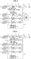
- Fig. 1 is a configuration diagram of a power system to which a distributed-power-supply power conversion system according to an embodiment 1 is applied.
- a plurality of photovoltaic power generation facilities 1 may be solar cells, for example, and are provided in an outdoor environment.
- Four photovoltaic power generation facilities 1 are shown in Fig. 1 .
- a system 2 is operated by a power company or the like.
- a distributed-power-supply power conversion system 3 is connected between the plurality of photovoltaic power generation facilities 1 and the system 2.
- the distributed-power-supply power conversion system 3 includes a plurality of power inverters 4, a plurality of DC-side switches 5, a plurality of transformers 6, a plurality of AC-side switches 7, a system-side switch 8, and a control device 9.
- An input portion of each of the plurality of power inverters 4 is connected to an output portion of each of the plurality of photovoltaic power generation facilities 1.
- Each of the plurality of power inverters 4 is provided such that the power inverter 4 can invert DC power from each of the plurality of photovoltaic power generation facilities to AC power.
- Each of the plurality of DC-side switches 5 is connected between each of the plurality of photovoltaic power generation facilities 1 and each of the plurality of power inverters 4.
- Each of the plurality of DC-side switches 5 may be a circuit breaker, for example.
- Each DC-side switch 5 is provided such that the DC-side switch 5 can cut the connection between each of the plurality of photovoltaic power generation facilities 1 and each of the plurality of power inverters 4 when an overcurrent occurs between each of the plurality of photovoltaic power generation facilities 1 and each of the plurality of power inverters 4.
- Each of the plurality of transformers 6 is connected between each of the plurality of power inverters 4 and the system 2. Each of the plurality of transformers 6 is provided such that the transformer 6 can transform an AC voltage from each of the plurality of power inverters 4.
- Each of the plurality of AC-side switches 7 is connected between each of the plurality of power inverters 4 and each of the plurality of transformers 6.
- Each of the plurality of AC-side switches 7 may be a circuit breaker, for example.
- Each AC-side switch 7 is provided such that the AC-side switch 7 can cut the connection between each of the plurality of power inverters 4 and each of the plurality of transformers 6 when an overcurrent occurs between each of the plurality of power inverters 4 and each of the plurality of transformers 6.
- the system-side switch 8 is provided between the plurality of transformers 6 and the system 2.
- the system-side switch 8 may be a circuit breaker, for example.
- the system-side switch 8 is provided such that the system-side switch 8 can cut the connection between the plurality of transformers 6 and the system 2 when an overcurrent occurs between the plurality of transformers 6 and the system 2.
- the control device 9 is provided such that the control device 9 can control the plurality of power inverters 4. Each of the plurality of power inverters 4 may be provided with the independent control device 9.
- a commissioning test is performed before the system 2 receives power. Specifically, in a state where the system-side switch 8 cuts the connection between the plurality of transformers 6 and the system 2, at least one power inverter 4 is selected from the plurality of power inverters 4 as the power inverter 4 used for testing.
- the AC-side switch 7 which corresponds to the power inverter 4 used for testing is maintained in a state of establishing the connection between the power inverter 4 used for testing and the transformer 6.
- Each of the other AC-side switches 7 is maintained in a state of cutting the connection between the power inverter 4 and the switch.
- an AC power supply device 10 and a load bank 11 are temporarily connected to the output side of the transformer 6 which corresponds to the power inverter 4 used for testing.
- the DC-side switch 5 which corresponds to the power inverter 4 used for testing is maintained in a state of establishing the connection between the photovoltaic power generation facility 1 and the power inverter 4 used for testing. Each of the other DC-side switches 5 is maintained in a state of cutting the connection between the photovoltaic power generation facility 1 and the power inverter 4.
- an energization test is performed by operating the power inverter 4 used for testing by the control device 9 in a state where the AC power supply device 10 establishes a voltage on the AC side of the power inverter 4 used for testing.
- the energization tests of the remaining power inverters 4 are sequentially performed by the same method.
- the energization test of the power inverter 4 used for testing is performed in a state where the AC side of the power inverter 4 used for testing is disconnected from the system 2, and is connected to the AC power supply device 10 and to the load bank 11, and a voltage on the AC side of the power inverter 4 used for testing is established. Effective power injected into the AC side is absorbed by the load bank 11. Therefore, it is possible to allow the power inverter 4 used for testing to output effective power. As a result, the energization test of the power inverter 4 can be performed before the system 2 receives power.
- a generator, an AC power supply, a motor generator, a power inverter or the like may be used as the AC power supply device 10.
- Output power from the power inverter 4 used for testing is consumed by the load bank 11. Therefore, it is sufficient for the AC power supply device 10 to output reactive power for maintaining an AC voltage.
- Rated power of the AC power supply device 10 may be smaller than that of the power inverter 4 used for testing.
- control device 9 Next, an example of the control device 9 will be described with reference to Fig. 2 .
- Fig. 2 is a hardware configuration diagram of the control device of the distributed-power-supply power conversion system according to the embodiment 1.
- control device 9 can be achieved by a processing circuitry.
- the processing circuitry may include at least one processor 100a and at least one memory 100b.
- the processing circuitry may include at least one dedicated hardware 200.
- the respective functions of the control device 9 is achieved by software, firmware, or a combination of the software and the firmware.
- At least one of the software and the firmware is referred to as a program.
- At least one of the software and the firmware is stored in at least one memory 100b.
- At least one processor 100a reads and executes the program stored in at least one memory 100b to achieve the respective functions of the control device 9.
- At least one processor 100a is also referred to as a central processing unit, a processing unit, an arithmetic unit, a microprocessor, a microcomputer, or a DSP.
- At least one memory 100b may be a nonvolatile or volatile semiconductor memory, such as a RAM, a ROM, a flash memory, an EPROM, or an EEPROM, or may be a magnetic disk, a flexible disk, an optical disc, a compact disc, a minidisc, a DVD or the like.
- the processing circuitry may be achieved by, for example, a single circuitry, a composite circuitry, a programmed processor, a parallel programmed processor, an ASIC, an FPGA, or a combination of the above.
- the respective functions of the control device 9 may be respectively achieved by the processing circuitries.
- the respective functions of the control device 9 may be collectively achieved by the processing circuitry.
- control device 9 may be achieved by the dedicated hardware 200, and other functions may be achieved by the software or the firmware.
- a function of controlling the power inverter 4 used for testing may be achieved by a processing circuitry formed of the dedicated hardware 200, and functions other than the function of controlling the power inverter 4 used for testing may be achieved by at least one processor 100a reading and executing the program stored in at least one memory 100b.
- the processing circuitry achieves the respective functions of the control device 9 by the hardware 200, the software, the firmware, or a combination of the above.
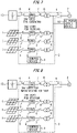
- Fig. 3 is a configuration diagram of a power system to which a distributed-power-supply power conversion system according to an embodiment 2 is applied. Components identical or corresponding to the components in the embodiment 1 are given the same reference symbols. The description of such components will be omitted.
- At least one power inverter 4 is selected from the plurality of power inverters 4 as a power inverter 4 used for maintaining AC voltage.
- a power inverter 4 different from the power inverter 4 used for maintaining AC voltage is selected as the power inverter 4 used for testing.
- the AC-side switch 7 which corresponds to the power inverter 4 used for maintaining AC voltage is maintained in a state of establishing the connection between the power inverter 4 used for maintaining AC voltage and the transformer 6.
- the AC-side switch 7 which corresponds to the power inverter 4 used for testing is maintained in a state of establishing the connection between the power inverter 4 used for testing and the transformer 6.
- Each of the other AC-side switches 7 is maintained in a state of cutting the connection between the power inverter 4 and the transformer 6.
- the load bank 11 is temporarily connected to the output side of the transformer 6 which corresponds to the power inverter 4 used for maintaining AC voltage and to the output side of the transformer 6 which corresponds to the power inverter 4 used for testing.
- the DC-side switch 5 which corresponds to the power inverter 4 used for maintaining AC voltage is maintained in a state of cutting the connection between the photovoltaic power generation facility 1 and the power inverter 4 used for maintaining voltage.
- the DC-side switch 5 which corresponds to the power inverter 4 used for testing is maintained in a state of establishing the connection between the photovoltaic power generation facility 1 and the power inverter 4 used for testing.
- Each of the other DC-side switches 5 is maintained in a state of cutting the connection between the photovoltaic power generation facility 1 and the power inverter 4.
- the control device 9 performs the energization test of the power inverter 4 used for testing while controlling the power inverter 4 used for maintaining AC voltage such that the power inverter 4 used for maintaining AC voltage has a constant voltage on the AC side.
- the power inverter 4 used for maintaining AC voltage controls the voltage on the AC side by outputting reactive power.
- the energization tests of the remaining power inverters 4 are sequentially performed by the same method.
- the power inverter 4 used for maintaining AC voltage is controlled such that the power inverter 4 used for maintaining voltage has a constant voltage on the AC side at the time of performing the energization test of the power inverter 4 used for testing. Further, effective power injected into the AC side is consumed by the load bank 11. Therefore, it is possible to allow the power inverter 4 used for testing to output effective power. Accordingly, before the system 2 receives power, the energization test of the power inverter 4 can be performed without requiring the AC power supply device 10.
- the power inverter 4 having the autonomous operation function is expensive due to authentication or the like. For this reason, with the use of the power inverter 4 having the AVR mode function, the energization test of the power inverter 4 can be performed at a low cost.
- Fig. 4 is a configuration diagram of a power system to which a distributed-power-supply power conversion system according to an embodiment 3 is applied. Components identical or corresponding to the components in the embodiment 2 are given the same reference symbols. The description of such components will be omitted.
- the AC-side switch 7 which corresponds to the power inverter 4 used for maintaining AC voltage is maintained in a state of establishing the connection between the power inverter 4 used for maintaining AC voltage and the transformer 6.
- the AC-side switch 7 which corresponds to the power inverter 4 used for testing is maintained in a state of establishing the connection between the power inverter 4 used for testing and the transformer 6.
- the DC-side switch 5 which corresponds to the power inverter 4 used for maintaining AC voltage is maintained in a state of establishing the connection between the photovoltaic power generation facility 1 and the power inverter 4 used for maintaining AC voltage.
- the DC-side switch 5 which corresponds to the power inverter 4 used for testing is maintained in a state of cutting the connection between the photovoltaic power generation facility 1 and the power inverter 4 used for testing.
- control device 9 performs the energization test of the power inverter 4 used for testing while controlling the power inverter 4 used for maintaining AC voltage such that the power inverter 4 used for maintaining AC voltage has a constant voltage on the AC side.
- the energization tests of the remaining power inverters 4 are sequentially performed by the same method.
- the power inverter 4 used for maintaining AC voltage is controlled such that the power inverter 4 used for maintaining AC voltage has a constant voltage on the AC side at the time of performing the energization test of the power inverter 4 used for testing. Further, AC power generated by the power inverter 4 used for testing is converted to DC power by the power inverter 4 used for maintaining AC voltage, and is applied to the DC side of the power inverter 4 used for testing again. Therefore, before the system 2 receives power, the energization test of the power inverter 4 can be performed without requiring either the AC power supply device 10 or the load bank 11.
- Fig. 5 is a configuration diagram of a power system to which a distributed-power-supply power conversion system according to an embodiment 4 is applied. Components identical or corresponding to the components in the embodiment 3 are given the same reference symbols. The description of such components will be omitted.
- the AC power supply device 10 is connected to the output side of the transformer 6 which corresponds to a power inverter 4 used for regeneration and to the output side of the transformer 6 which corresponds to the power inverter 4 used for testing.
- the energization test of the power inverter 4 used for testing is performed by the control device 9 while the regenerative operation of the power inverter 4 used for regeneration is performed by the control device 9 such that power generated by the power inverter 4 used for testing is regenerated to the DC side.
- the energization tests of the remaining power inverters 4 are sequentially performed by the same method.
- the regenerative operation of the power inverter 4 used for regeneration is performed at the time of performing the energization test of the power inverter 4 used for testing. Therefore, before the system 2 receives power, the energization test of the power inverter 4 can be performed by the AC power supply device 10 with a small capacity.
- Fig. 6 is a configuration diagram of a power system to which a distributed-power-supply power conversion system according to an embodiment 5 is applied. Components identical or corresponding to the components in the embodiment 4 are given the same reference symbols. The description of such components will be omitted.
- the DC-side switch 5 which corresponds to the power inverter 4 used for maintaining DC voltage is maintained in a state of cutting the connection between the photovoltaic power generation facility 1 and the power inverter 4 used for maintaining DC voltage.
- the control device 9 performs the energization test of the power inverter 4 used for testing while controlling the power inverter 4 used for maintaining DC voltage such that the power inverter 4 used for maintaining DC voltage has a constant voltage on the DC side.
- the energization tests of the remaining power inverters 4 are sequentially performed by the same method.
- the power inverter 4 used for maintaining DC voltage is controlled such that the power inverter 4 used for maintaining DC voltage has a constant voltage on the DC side at the time of performing the energization test of the power inverter 4 used for testing. Therefore, even when the connection with a DC power supply is not established before the system 2 receives power, the energization test of the power inverter 4 can be performed by the AC power supply device 10 with a small capacity.
- Fig. 7 is a configuration diagram of a power system to which a distributed-power-supply power conversion system according to an embodiment 6 is applied. Components identical or corresponding to the components in the embodiment 2 are given the same reference symbols. The description of such components will be omitted.
- the power inverter 4 having the DC side to which a power storage facility 13 is connected is selected as a power inverter 4 used for charging.
- a power inverter 4 different from the power inverter 4 used for charging is selected as the power inverter 4 used for testing.
- the DC-side switch 5 which corresponds to the power inverter 4 used for charging is maintained in a state of establishing the connection between the power storage facility 13 and the power inverter 4 used for charging.
- the DC-side switch 5 which corresponds to the power inverter 4 used for testing is maintained in a state of establishing the connection between the photovoltaic power generation facility 1 and the power inverter 4 used for testing.
- the AC power supply device 10 is connected to the output side of the transformer 6 which corresponds to the power inverter 4 used for charging and to the output side of the transformer 6 which corresponds to the power inverter 4 used for testing.
- the energization test of the power inverter 4 used for testing is performed by the control device 9 while the charging operation of the power inverter 4 used for charging is performed by the control device 9 such that the power inverter 4 used for charging is charged with power generated by the power inverter 4 used for testing.
- the energization tests of the remaining power inverters 4 are sequentially performed by the same method.
- Power charged into the power storage facility 13 may be discharged by a discharging resistor which is provided on the DC side or the AC side.
- the regenerative operation of the power inverter 4 used for charging is performed at the time of performing the energization test of the power inverter 4 used for testing. Therefore, before the system 2 receives power, the energization test of the power inverter 4 can be performed while power from the photovoltaic power generation facility 1 and the AC power supply device 10 with a small capacity is absorbed by the power storage facility 13.
- Fig. 8 is a configuration diagram of a power system to which a distributed-power-supply power conversion system according to an embodiment 7 is applied. Components identical or corresponding to the components in the embodiment 6 are given the same reference symbols. The description of such components will be omitted.
- control device 9 performs the energization test of the power inverter 4 used for testing while controlling the power inverter 4 used for maintaining AC voltage such that the power inverter 4 used for maintaining AC voltage has a constant voltage on the AC side.
- the energization tests of the remaining power inverters 4 are sequentially performed by the same method.
- the power inverter 4 used for maintaining AC voltage is controlled such that the power inverter 4 used for maintaining AC voltage has a constant voltage on the AC side at the time of performing the energization test of the power inverter 4 used for testing. Therefore, before the system 2 receives power, the energization test of the power inverter 4 can be performed without requiring the AC power supply device 10 while power from the photovoltaic power generation facility 1 is absorbed by the power storage facility 13.
- the energization test of the power inverter 4 may be performed by the same method even without the transformer 6.
- the embodiment 2 to the embodiment 7 it may be configured such that a plurality of power inverters 4 for maintaining voltage are divided into groups, and the energization test of the power inverter 4 used for testing may be simultaneously performed in a plurality of groups. In this case, all energization tests of the power inverters 4 can be finished within a short period of time.
- the distributed-power-supply power conversion system according to this invention can be utilized in a power system.
Landscapes
- Engineering & Computer Science (AREA)
- Power Engineering (AREA)
- Physics & Mathematics (AREA)
- General Physics & Mathematics (AREA)
- Inverter Devices (AREA)
- Amplifiers (AREA)
- Polarising Elements (AREA)
- Supply And Distribution Of Alternating Current (AREA)
- Stand-By Power Supply Arrangements (AREA)
Abstract
Description
- This invention relates to a distributed-power-supply power conversion system.
- PTL 1 discloses a distributed-power-supply power conversion system. With the use of this distributed-power-supply power conversion system, when a plurality of power conversion devices are operated by one common control device, operation control information can be transmitted without providing a dedicated signal line.
- [PTL 1]
JP H10-201105 A - However, in the distributed-power-supply power conversion system disclosed in PTL 1, the energization test of the power inverter is performed after the system starts to receive power. Therefore, if it takes a long time to prepare a power receiving facility in the system, the energization test of the power inverter cannot be performed. As a result, there is a delay in the start of selling power.
- This invention has been made to overcome the above-mentioned problem. It is an object of this invention to provide a distributed-power-supply power conversion system which can perform the energization test of the power inverter before the system receives power.
- A distributed-power-supply power conversion system according to this invention includes: a plurality of power inverters configured to invert DC power to AC power; and a control device configured to select at least one power inverter from the plurality of power inverters as a power inverter used for testing, and configured to perform an energization test of the power inverter used for testing in a state where an AC side of the power inverter used for testing is disconnected from a system, and is connected to an AC power supply device and to a load bank, and a voltage on the AC side of the power inverter used for testing is established.
- A distributed-power-supply power conversion system according to this invention includes: a plurality of power inverters configured to invert DC power to AC power; and a control device configured to select at least one power inverter from the plurality of power inverters as a power inverter used for maintaining voltage, configured to select, from the plurality of power inverters, at least one power inverter different from the power inverter used for maintaining voltage as a power inverter used for testing, and configured to perform an energization test of the power inverter used for testing in a state where a voltage on the AC side of the power inverter used for maintaining voltage is maintained at a constant value, an AC side of the power inverter used for maintaining voltage and an AC side of the power inverter used for testing being disconnected from a system, and being connected with each other.
- A distributed-power-supply power conversion system according to this invention includes: a plurality of power inverters configured to invert DC power to AC power; and a control device configured to select at least one power inverter from the plurality of power inverters as a power inverter used for regeneration, configured to select, from the plurality of power inverters, a power inverter different from the power inverter used for regeneration as a power inverter used for testing, and configured to perform an energization test of the power inverter used for testing, an AC side of the power inverter used for regeneration and an AC side of the power inverter used for testing being disconnected from a system, and being connected with each other, the control device selecting, as the power inverter used for regeneration, the power inverter having a DC side to which a photovoltaic power generation facility is connected, selecting, as the power inverter used for testing, the power inverter having a DC side to which the photovoltaic power generation facility is connected and, in a state where the AC side of the power inverter used for regeneration and the AC side of the power inverter used for testing are connected to an AC power supply device, performing a regenerative operation of the power inverter used for regeneration at a time of performing the energization test of the power inverter used for testing.
- A distributed-power-supply power conversion system according to this invention includes: a plurality of power inverters configured to invert DC power to AC power; and a control device configured to select at least one power inverter from the plurality of power inverters as a power inverter used for charging, configured to select, from the plurality of power inverters, a power inverter different from the power inverter used for charging as a power inverter used for testing, and configured to perform an energization test of the power inverter used for testing, an AC side of the power inverter used for charging and an AC side of the power inverter used for testing being disconnected from a system, and being connected with each other, the control device selecting, as the power inverter used for charging, the power inverter having a DC side to which a power storage facility is connected, selecting, as the power inverter used for testing, the power inverter having a DC side to which a photovoltaic power generation facility is connected and, in a state where the AC side of the power inverter used for charging and the AC side of the power inverter used for testing are connected to the AC power supply device, performing a charging operation of the power inverter used for charging at a time of performing the energization test of the power inverter used for testing.
- According to these inventions, the energization test of the power inverter can be performed before the system receives power.
-
- [
Fig. 1 ]
Fig. 1 is a configuration diagram of a power system to which a distributed-power-supply power conversion system according to an embodiment 1 is applied. - [
Fig. 2 ]
Fig. 2 is a hardware configuration diagram of a control device of the distributed-power-supply power conversion system according to the embodiment 1. - [
Fig. 3 ]
Fig. 3 is a configuration diagram of a power system to which a distributed-power-supply power conversion system according to anembodiment 2 is applied. - [
Fig. 4 ]
Fig. 4 is a configuration diagram of a power system to which a distributed-power-supply power conversion system according to anembodiment 3 is applied. - [
Fig. 5 ]
Fig. 5 is a configuration diagram of a power system to which a distributed-power-supply power conversion system according to anembodiment 4 is applied. - [
Fig. 6 ]
Fig. 6 is a configuration diagram of a power system to which a distributed-power-supply power conversion system according to anembodiment 5 is applied. - [
Fig. 7 ]
Fig. 7 is a configuration diagram of a power system to which a distributed-power-supply power conversion system according to anembodiment 6 is applied. - [
Fig. 8 ]
Fig. 8 is a configuration diagram of a power system to which a distributed-power-supply power conversion system according to anembodiment 7 is applied. - Modes for carrying out this invention will be described with reference to attached drawings. In the respective drawings, identical or corresponding components are given the same reference symbols. The repetitive descriptions of such components will be simplified or omitted when appropriate.
-
Fig. 1 is a configuration diagram of a power system to which a distributed-power-supply power conversion system according to an embodiment 1 is applied. - In the power system shown in
Fig. 1 , a plurality of photovoltaic power generation facilities 1 may be solar cells, for example, and are provided in an outdoor environment. Four photovoltaic power generation facilities 1 are shown inFig. 1 . Asystem 2 is operated by a power company or the like. A distributed-power-supplypower conversion system 3 is connected between the plurality of photovoltaic power generation facilities 1 and thesystem 2. - The distributed-power-supply
power conversion system 3 includes a plurality ofpower inverters 4, a plurality of DC-side switches 5, a plurality oftransformers 6, a plurality of AC-side switches 7, a system-side switch 8, and acontrol device 9. - An input portion of each of the plurality of
power inverters 4 is connected to an output portion of each of the plurality of photovoltaic power generation facilities 1. Each of the plurality ofpower inverters 4 is provided such that thepower inverter 4 can invert DC power from each of the plurality of photovoltaic power generation facilities to AC power. - Each of the plurality of DC-
side switches 5 is connected between each of the plurality of photovoltaic power generation facilities 1 and each of the plurality ofpower inverters 4. Each of the plurality of DC-side switches 5 may be a circuit breaker, for example. Each DC-side switch 5 is provided such that the DC-side switch 5 can cut the connection between each of the plurality of photovoltaic power generation facilities 1 and each of the plurality ofpower inverters 4 when an overcurrent occurs between each of the plurality of photovoltaic power generation facilities 1 and each of the plurality ofpower inverters 4. - Each of the plurality of
transformers 6 is connected between each of the plurality ofpower inverters 4 and thesystem 2. Each of the plurality oftransformers 6 is provided such that thetransformer 6 can transform an AC voltage from each of the plurality ofpower inverters 4. - Each of the plurality of AC-
side switches 7 is connected between each of the plurality ofpower inverters 4 and each of the plurality oftransformers 6. Each of the plurality of AC-side switches 7 may be a circuit breaker, for example. Each AC-side switch 7 is provided such that the AC-side switch 7 can cut the connection between each of the plurality ofpower inverters 4 and each of the plurality oftransformers 6 when an overcurrent occurs between each of the plurality ofpower inverters 4 and each of the plurality oftransformers 6. - The system-
side switch 8 is provided between the plurality oftransformers 6 and thesystem 2. The system-side switch 8 may be a circuit breaker, for example. The system-side switch 8 is provided such that the system-side switch 8 can cut the connection between the plurality oftransformers 6 and thesystem 2 when an overcurrent occurs between the plurality oftransformers 6 and thesystem 2. - The
control device 9 is provided such that thecontrol device 9 can control the plurality ofpower inverters 4. Each of the plurality ofpower inverters 4 may be provided with theindependent control device 9. - In the distributed-power-supply
power conversion system 3, a commissioning test is performed before thesystem 2 receives power. Specifically, in a state where the system-side switch 8 cuts the connection between the plurality oftransformers 6 and thesystem 2, at least onepower inverter 4 is selected from the plurality ofpower inverters 4 as thepower inverter 4 used for testing. - The AC-
side switch 7 which corresponds to thepower inverter 4 used for testing is maintained in a state of establishing the connection between thepower inverter 4 used for testing and thetransformer 6. Each of the other AC-side switches 7 is maintained in a state of cutting the connection between thepower inverter 4 and the switch. - In such a state, an AC
power supply device 10 and aload bank 11 are temporarily connected to the output side of thetransformer 6 which corresponds to thepower inverter 4 used for testing. - The DC-
side switch 5 which corresponds to thepower inverter 4 used for testing is maintained in a state of establishing the connection between the photovoltaic power generation facility 1 and thepower inverter 4 used for testing. Each of the other DC-side switches 5 is maintained in a state of cutting the connection between the photovoltaic power generation facility 1 and thepower inverter 4. - In such a state, an energization test is performed by operating the
power inverter 4 used for testing by thecontrol device 9 in a state where the ACpower supply device 10 establishes a voltage on the AC side of thepower inverter 4 used for testing. - After the energization test of the
power inverter 4 used for testing at a current point of time is finished, the energization tests of the remainingpower inverters 4 are sequentially performed by the same method. - According to the embodiment 1 described above, the energization test of the
power inverter 4 used for testing is performed in a state where the AC side of thepower inverter 4 used for testing is disconnected from thesystem 2, and is connected to the ACpower supply device 10 and to theload bank 11, and a voltage on the AC side of thepower inverter 4 used for testing is established. Effective power injected into the AC side is absorbed by theload bank 11. Therefore, it is possible to allow thepower inverter 4 used for testing to output effective power. As a result, the energization test of thepower inverter 4 can be performed before thesystem 2 receives power. - A generator, an AC power supply, a motor generator, a power inverter or the like may be used as the AC
power supply device 10. - Output power from the
power inverter 4 used for testing is consumed by theload bank 11. Therefore, it is sufficient for the ACpower supply device 10 to output reactive power for maintaining an AC voltage. Rated power of the ACpower supply device 10 may be smaller than that of thepower inverter 4 used for testing. - Next, an example of the
control device 9 will be described with reference toFig. 2 . -
Fig. 2 is a hardware configuration diagram of the control device of the distributed-power-supply power conversion system according to the embodiment 1. - The respective functions of the
control device 9 can be achieved by a processing circuitry. For example, the processing circuitry may include at least oneprocessor 100a and at least onememory 100b. For example, the processing circuitry may include at least onededicated hardware 200. - In the case where the processing circuitry includes at least one
processor 100a and at least onememory 100b, the respective functions of thecontrol device 9 is achieved by software, firmware, or a combination of the software and the firmware. At least one of the software and the firmware is referred to as a program. At least one of the software and the firmware is stored in at least onememory 100b. At least oneprocessor 100a reads and executes the program stored in at least onememory 100b to achieve the respective functions of thecontrol device 9. At least oneprocessor 100a is also referred to as a central processing unit, a processing unit, an arithmetic unit, a microprocessor, a microcomputer, or a DSP. For example, at least onememory 100b may be a nonvolatile or volatile semiconductor memory, such as a RAM, a ROM, a flash memory, an EPROM, or an EEPROM, or may be a magnetic disk, a flexible disk, an optical disc, a compact disc, a minidisc, a DVD or the like. - In the case where the processing circuitry includes at least one
dedicated hardware 200, the processing circuitry may be achieved by, for example, a single circuitry, a composite circuitry, a programmed processor, a parallel programmed processor, an ASIC, an FPGA, or a combination of the above. For example, the respective functions of thecontrol device 9 may be respectively achieved by the processing circuitries. For example, the respective functions of thecontrol device 9 may be collectively achieved by the processing circuitry. - Some of the respective functions of the
control device 9 may be achieved by thededicated hardware 200, and other functions may be achieved by the software or the firmware. For example, a function of controlling thepower inverter 4 used for testing may be achieved by a processing circuitry formed of thededicated hardware 200, and functions other than the function of controlling thepower inverter 4 used for testing may be achieved by at least oneprocessor 100a reading and executing the program stored in at least onememory 100b. - As described above, the processing circuitry achieves the respective functions of the
control device 9 by thehardware 200, the software, the firmware, or a combination of the above. -
Fig. 3 is a configuration diagram of a power system to which a distributed-power-supply power conversion system according to anembodiment 2 is applied. Components identical or corresponding to the components in the embodiment 1 are given the same reference symbols. The description of such components will be omitted. - In the commissioning test of the distributed-power-supply
power conversion system 3 of theembodiment 2, in a state where the system-side switch 8 cuts the connection between the plurality oftransformers 6 and thesystem 2, at least onepower inverter 4 is selected from the plurality ofpower inverters 4 as apower inverter 4 used for maintaining AC voltage. Of the plurality ofpower inverters 4, apower inverter 4 different from thepower inverter 4 used for maintaining AC voltage is selected as thepower inverter 4 used for testing. - The AC-
side switch 7 which corresponds to thepower inverter 4 used for maintaining AC voltage is maintained in a state of establishing the connection between thepower inverter 4 used for maintaining AC voltage and thetransformer 6. The AC-side switch 7 which corresponds to thepower inverter 4 used for testing is maintained in a state of establishing the connection between thepower inverter 4 used for testing and thetransformer 6. Each of the other AC-side switches 7 is maintained in a state of cutting the connection between thepower inverter 4 and thetransformer 6. - In such a state, the
load bank 11 is temporarily connected to the output side of thetransformer 6 which corresponds to thepower inverter 4 used for maintaining AC voltage and to the output side of thetransformer 6 which corresponds to thepower inverter 4 used for testing. - The DC-
side switch 5 which corresponds to thepower inverter 4 used for maintaining AC voltage is maintained in a state of cutting the connection between the photovoltaic power generation facility 1 and thepower inverter 4 used for maintaining voltage. The DC-side switch 5 which corresponds to thepower inverter 4 used for testing is maintained in a state of establishing the connection between the photovoltaic power generation facility 1 and thepower inverter 4 used for testing. Each of the other DC-side switches 5 is maintained in a state of cutting the connection between the photovoltaic power generation facility 1 and thepower inverter 4. - In such a state, the
control device 9 performs the energization test of thepower inverter 4 used for testing while controlling thepower inverter 4 used for maintaining AC voltage such that thepower inverter 4 used for maintaining AC voltage has a constant voltage on the AC side. Thepower inverter 4 used for maintaining AC voltage controls the voltage on the AC side by outputting reactive power. - After the energization test of the
power inverter 4 used for testing at a current point of time is finished, the energization tests of the remainingpower inverters 4 are sequentially performed by the same method. - According to the
embodiment 2 described above, in a state where the AC side of thepower inverter 4 used for maintaining voltage and the AC side of thepower inverter 4 used for testing are connected to theload bank 11, thepower inverter 4 used for maintaining AC voltage is controlled such that thepower inverter 4 used for maintaining voltage has a constant voltage on the AC side at the time of performing the energization test of thepower inverter 4 used for testing. Further, effective power injected into the AC side is consumed by theload bank 11. Therefore, it is possible to allow thepower inverter 4 used for testing to output effective power. Accordingly, before thesystem 2 receives power, the energization test of thepower inverter 4 can be performed without requiring the ACpower supply device 10. - In the
embodiment 2, it is sufficient that at least twopower inverters 4 have an autonomous operation function or an AVR mode function. Thepower inverter 4 having the autonomous operation function is expensive due to authentication or the like. For this reason, with the use of thepower inverter 4 having the AVR mode function, the energization test of thepower inverter 4 can be performed at a low cost. -
Fig. 4 is a configuration diagram of a power system to which a distributed-power-supply power conversion system according to anembodiment 3 is applied. Components identical or corresponding to the components in theembodiment 2 are given the same reference symbols. The description of such components will be omitted. - In the commissioning test of the distributed-power-supply
power conversion system 3 of theembodiment 3, the AC-side switch 7 which corresponds to thepower inverter 4 used for maintaining AC voltage is maintained in a state of establishing the connection between thepower inverter 4 used for maintaining AC voltage and thetransformer 6. The AC-side switch 7 which corresponds to thepower inverter 4 used for testing is maintained in a state of establishing the connection between thepower inverter 4 used for testing and thetransformer 6. - In such a state, the DC side of the
power inverter 4 used for maintaining AC voltage and the DC side of thepower inverter 4 used for testing are temporarily connected via atest cable 12. - The DC-
side switch 5 which corresponds to thepower inverter 4 used for maintaining AC voltage is maintained in a state of establishing the connection between the photovoltaic power generation facility 1 and thepower inverter 4 used for maintaining AC voltage. The DC-side switch 5 which corresponds to thepower inverter 4 used for testing is maintained in a state of cutting the connection between the photovoltaic power generation facility 1 and thepower inverter 4 used for testing. - In such a state, the
control device 9 performs the energization test of thepower inverter 4 used for testing while controlling thepower inverter 4 used for maintaining AC voltage such that thepower inverter 4 used for maintaining AC voltage has a constant voltage on the AC side. - After the energization test of the
power inverter 4 used for testing at a current point of time is finished, the energization tests of the remainingpower inverters 4 are sequentially performed by the same method. - According to the
embodiment 3 described above, in a state where the DC side of thepower inverter 4 used for testing and the DC side of thepower inverter 4 used for maintaining AC voltage are used in common, thepower inverter 4 used for maintaining AC voltage is controlled such that thepower inverter 4 used for maintaining AC voltage has a constant voltage on the AC side at the time of performing the energization test of thepower inverter 4 used for testing. Further, AC power generated by thepower inverter 4 used for testing is converted to DC power by thepower inverter 4 used for maintaining AC voltage, and is applied to the DC side of thepower inverter 4 used for testing again. Therefore, before thesystem 2 receives power, the energization test of thepower inverter 4 can be performed without requiring either the ACpower supply device 10 or theload bank 11. -
Fig. 5 is a configuration diagram of a power system to which a distributed-power-supply power conversion system according to anembodiment 4 is applied. Components identical or corresponding to the components in theembodiment 3 are given the same reference symbols. The description of such components will be omitted. - In the commissioning test of the distributed-power-supply
power conversion system 3 of theembodiment 4, the ACpower supply device 10 is connected to the output side of thetransformer 6 which corresponds to apower inverter 4 used for regeneration and to the output side of thetransformer 6 which corresponds to thepower inverter 4 used for testing. - In such a state, with the AC
power supply device 10 establishing the voltage on the AC side of thepower inverter 4 used for testing, the energization test of thepower inverter 4 used for testing is performed by thecontrol device 9 while the regenerative operation of thepower inverter 4 used for regeneration is performed by thecontrol device 9 such that power generated by thepower inverter 4 used for testing is regenerated to the DC side. - After the energization test of the
power inverter 4 used for testing at a current point of time is finished, the energization tests of the remainingpower inverters 4 are sequentially performed by the same method. - According to the
embodiment 4 described above, in a state where the AC side of thepower inverter 4 used for regeneration and the AC side of thepower inverter 4 used for testing are connected to the ACpower supply device 10, the regenerative operation of thepower inverter 4 used for regeneration is performed at the time of performing the energization test of thepower inverter 4 used for testing. Therefore, before thesystem 2 receives power, the energization test of thepower inverter 4 can be performed by the ACpower supply device 10 with a small capacity. -
Fig. 6 is a configuration diagram of a power system to which a distributed-power-supply power conversion system according to anembodiment 5 is applied. Components identical or corresponding to the components in theembodiment 4 are given the same reference symbols. The description of such components will be omitted. - In the commissioning test of the distributed-power-supply
power conversion system 3 of theembodiment 5, the DC-side switch 5 which corresponds to thepower inverter 4 used for maintaining DC voltage is maintained in a state of cutting the connection between the photovoltaic power generation facility 1 and thepower inverter 4 used for maintaining DC voltage. - In such a state, with the AC
power supply device 10 establishing the voltage on the AC side of thepower inverter 4 used for testing, thecontrol device 9 performs the energization test of thepower inverter 4 used for testing while controlling thepower inverter 4 used for maintaining DC voltage such that thepower inverter 4 used for maintaining DC voltage has a constant voltage on the DC side. - After the energization test of the
power inverter 4 used for testing at a current point of time is finished, the energization tests of the remainingpower inverters 4 are sequentially performed by the same method. - According to the
embodiment 5 described above, in a state where the DC side of thepower inverter 4 used for maintaining DC voltage and the DC side of thepower inverter 4 used for testing are connected with each other, and the AC side of thepower inverter 4 used for maintaining DC voltage and the AC side of thepower inverter 4 used for testing are connected to the ACpower supply device 10, thepower inverter 4 used for maintaining DC voltage is controlled such that thepower inverter 4 used for maintaining DC voltage has a constant voltage on the DC side at the time of performing the energization test of thepower inverter 4 used for testing. Therefore, even when the connection with a DC power supply is not established before thesystem 2 receives power, the energization test of thepower inverter 4 can be performed by the ACpower supply device 10 with a small capacity. -
Fig. 7 is a configuration diagram of a power system to which a distributed-power-supply power conversion system according to anembodiment 6 is applied. Components identical or corresponding to the components in theembodiment 2 are given the same reference symbols. The description of such components will be omitted. - In the commissioning test of the distributed-power-supply
power conversion system 3 of theembodiment 6, in a state where the system-side switch 8 cuts the connection between the plurality oftransformers 6 and thesystem 2, thepower inverter 4 having the DC side to which apower storage facility 13 is connected is selected as apower inverter 4 used for charging. Of the plurality ofpower inverters 4, apower inverter 4 different from thepower inverter 4 used for charging is selected as thepower inverter 4 used for testing. - The DC-
side switch 5 which corresponds to thepower inverter 4 used for charging is maintained in a state of establishing the connection between thepower storage facility 13 and thepower inverter 4 used for charging. The DC-side switch 5 which corresponds to thepower inverter 4 used for testing is maintained in a state of establishing the connection between the photovoltaic power generation facility 1 and thepower inverter 4 used for testing. - The AC
power supply device 10 is connected to the output side of thetransformer 6 which corresponds to thepower inverter 4 used for charging and to the output side of thetransformer 6 which corresponds to thepower inverter 4 used for testing. - In such a state, with the AC
power supply device 10 establishing the voltage on the AC side of thepower inverter 4 used for testing, the energization test of thepower inverter 4 used for testing is performed by thecontrol device 9 while the charging operation of thepower inverter 4 used for charging is performed by thecontrol device 9 such that thepower inverter 4 used for charging is charged with power generated by thepower inverter 4 used for testing. - After the energization test of the
power inverter 4 used for testing at a current point of time is finished, the energization tests of the remainingpower inverters 4 are sequentially performed by the same method. - Power charged into the
power storage facility 13 may be discharged by a discharging resistor which is provided on the DC side or the AC side. - According to the
embodiment 6 described above, in a state where the AC side of thepower inverter 4 used for charging and the AC side of thepower inverter 4 used for testing are connected to the ACpower supply device 10, the regenerative operation of thepower inverter 4 used for charging is performed at the time of performing the energization test of thepower inverter 4 used for testing. Therefore, before thesystem 2 receives power, the energization test of thepower inverter 4 can be performed while power from the photovoltaic power generation facility 1 and the ACpower supply device 10 with a small capacity is absorbed by thepower storage facility 13. -
Fig. 8 is a configuration diagram of a power system to which a distributed-power-supply power conversion system according to anembodiment 7 is applied. Components identical or corresponding to the components in theembodiment 6 are given the same reference symbols. The description of such components will be omitted. - In the commissioning test of the distributed-power-supply
power conversion system 3 of theembodiment 7, thecontrol device 9 performs the energization test of thepower inverter 4 used for testing while controlling thepower inverter 4 used for maintaining AC voltage such that thepower inverter 4 used for maintaining AC voltage has a constant voltage on the AC side. - After the energization test of the
power inverter 4 used for testing at a current point of time is finished, the energization tests of the remainingpower inverters 4 are sequentially performed by the same method. - According to the
embodiment 7 described above, thepower inverter 4 used for maintaining AC voltage is controlled such that thepower inverter 4 used for maintaining AC voltage has a constant voltage on the AC side at the time of performing the energization test of thepower inverter 4 used for testing. Therefore, before thesystem 2 receives power, the energization test of thepower inverter 4 can be performed without requiring the ACpower supply device 10 while power from the photovoltaic power generation facility 1 is absorbed by thepower storage facility 13. - It is noted that, in the embodiment 1 to the
embodiment 7, the energization test of thepower inverter 4 may be performed by the same method even without thetransformer 6. - Further, in the
embodiment 2 to theembodiment 7, it may be configured such that a plurality ofpower inverters 4 for maintaining voltage are divided into groups, and the energization test of thepower inverter 4 used for testing may be simultaneously performed in a plurality of groups. In this case, all energization tests of thepower inverters 4 can be finished within a short period of time. - As described above, the distributed-power-supply power conversion system according to this invention can be utilized in a power system.
-
- 1
- photovoltaic power generation facility
- 2
- system
- 3
- distributed-power-supply power conversion system
- 4
- power inverter
- 5
- DC-side switch
- 6
- transformer
- 7
- AC-side switch
- 8
- system-side switch
- 9
- control device
- 10
- AC power supply device
- 11
- load bank
- 12
- test cable
- 13
- power storage facility
- 100a
- processor
- 100b
- memory
- 200
- hardware
Claims (8)
- A distributed-power-supply power conversion system comprising:a plurality of power inverters configured to invert DC power to AC power; anda control device configured to select at least one power inverter from the plurality of power inverters as a power inverter used for testing, and configured to perform an energization test of the power inverter used for testing in a state where an AC side of the power inverter used for testing is disconnected from a system, and is connected to an AC power supply device and to a load bank, and a voltage on the AC side of the power inverter used for testing is established.
- A distributed-power-supply power conversion system comprising:a plurality of power inverters configured to invert DC power to AC power; anda control device configured to select at least one power inverter from the plurality of power inverters as a power inverter used for maintaining voltage, configured to select, from the plurality of power inverters, a power inverter different from the power inverter used for maintaining voltage as a power inverter used for testing, and configured to perform an energization test of the power inverter used for testing, an AC side of the power inverter used for maintaining voltage and an AC side of the power inverter used for testing being disconnected from a system, and being connected with each other.
- The distributed-power-supply power conversion system according to claim 2, wherein
the control device selects, as the power inverter used for maintaining voltage, the power inverter having a DC side from which a DC power supply is disconnected, selects, as the power inverter used for testing, the power inverter having a DC side to which a photovoltaic power generation facility is connected and, in a state where the AC side of the power inverter used for maintaining voltage and the AC side of the power inverter used for testing are connected to a load bank, controls the power inverter used for maintaining voltage such that the power inverter used for maintaining voltage has a constant voltage on the AC side at a time of performing the energization test of the power inverter used for testing. - The distributed-power-supply power conversion system according to claim 2, wherein
the control device selects, as the power inverter used for maintaining voltage, the power inverter having a DC side to which a photovoltaic power generation facility is connected, selects, as the power inverter used for testing, the power inverter having a DC side to which the photovoltaic power generation facility is connected, and controls the power inverter used for maintaining voltage such that the power inverter used for maintaining voltage has a constant voltage on the AC side at a time of performing the energization test of the power inverter used for testing. - A distributed-power-supply power conversion system comprising:a plurality of power inverters configured to invert DC power to AC power; anda control device configured to select at least one power inverter from the plurality of power inverters as a power inverter used for regeneration, configured to select, from the plurality of power inverters, a power inverter different from the power inverter used for regeneration as a power inverter used for testing, and configured to perform an energization test of the power inverter used for testing, an AC side of the power inverter used for regeneration and an AC side of the power inverter used for testing being disconnected from a system, and being connected with each other,the control device selecting, as the power inverter used for regeneration, the power inverter having a DC side to which a photovoltaic power generation facility is connected, selecting, as the power inverter used for testing, the power inverter having a DC side to which the photovoltaic power generation facility is connected and, in a state where the AC side of the power inverter used for regeneration and the AC side of the power inverter used for testing are connected to an AC power supply device, performing a regenerative operation of the power inverter used for regeneration at a time of performing the energization test of the power inverter used for testing.
- The distributed-power-supply power conversion system according to claim 2, wherein
the control device selects, as the power inverter used for maintaining voltage, the power inverter having a DC side from which a DC power supply is disconnected, selects, as the power inverter used for testing, the power inverter having a DC side from which the DC power supply is disconnected and, in a state where the DC side of the power inverter used for maintaining voltage and the DC side of the power inverter used for testing are connected with each other and the AC side of the power inverter used for maintaining voltage and the AC side of the power inverter used for testing are connected to an AC power supply device, controls the power inverter used for maintaining voltage such that the power inverter used for maintaining voltage has a constant voltage on the DC side at a time of performing the energization test of the power inverter used for testing. - A distributed-power-supply power conversion system comprising:a plurality of power inverters configured to invert DC power to AC power; anda control device configured to select at least one power inverter from the plurality of power inverters as a power inverter used for charging, configured to select, from the plurality of power inverters, a power inverter different from the power inverter used for charging as a power inverter used for testing, and configured to perform an energization test of the power inverter used for testing, an AC side of the power inverter used for charging and an AC side of the power inverter used for testing being disconnected from a system, and being connected with each other,the control device selecting, as the power inverter used for charging, the power inverter having a DC side to which a power storage facility is connected, selecting, as the power inverter used for testing, the power inverter having a DC side to which a photovoltaic power generation facility is connected and, in a state where the AC side of the power inverter used for charging and the AC side of the power inverter used for testing are connected to the AC power supply device, performing a charging operation of the power inverter used for charging at a time of performing the energization test of the power inverter used for testing.
- The distributed-power-supply power conversion system according to claim 2, wherein
the control device selects, as the power inverter used for maintaining voltage, the power inverter having a DC side to which a power storage facility is connected, selects, as the power inverter used for testing, the power inverter having a DC side to which a photovoltaic power generation facility is connected, and controls the power inverter used for maintaining voltage such that the power inverter used for maintaining voltage has a constant voltage on the AC side at a time of performing the energization test of the power inverter used for testing.
Applications Claiming Priority (1)
| Application Number | Priority Date | Filing Date | Title |
|---|---|---|---|
| PCT/JP2020/004968 WO2021157087A1 (en) | 2020-02-07 | 2020-02-07 | Power conversion system for dispersed power source |
Publications (2)
| Publication Number | Publication Date |
|---|---|
| EP4102714A1 true EP4102714A1 (en) | 2022-12-14 |
| EP4102714A4 EP4102714A4 (en) | 2023-11-08 |
Family
ID=77199821
Family Applications (1)
| Application Number | Title | Priority Date | Filing Date |
|---|---|---|---|
| EP20917907.6A Pending EP4102714A4 (en) | 2020-02-07 | 2020-02-07 | POWER CONVERSION SYSTEM FOR A DISPERSED ENERGY SOURCE |
Country Status (6)
| Country | Link |
|---|---|
| US (1) | US11901737B2 (en) |
| EP (1) | EP4102714A4 (en) |
| JP (1) | JP7632315B2 (en) |
| CN (1) | CN114503419A (en) |
| AU (1) | AU2020426967B2 (en) |
| WO (1) | WO2021157087A1 (en) |
Families Citing this family (1)
| Publication number | Priority date | Publication date | Assignee | Title |
|---|---|---|---|---|
| US12051895B2 (en) * | 2022-10-26 | 2024-07-30 | Bloom Energy Corporation | Auxiliary circuit to inject fault current during grid faults |
Family Cites Families (10)
| Publication number | Priority date | Publication date | Assignee | Title |
|---|---|---|---|---|
| JPH10201105A (en) | 1997-01-14 | 1998-07-31 | Nissin Electric Co Ltd | Photovoltaic power generation system |
| JP3330519B2 (en) * | 1997-08-11 | 2002-09-30 | 三菱電機株式会社 | Electronic watt-hour meter and its error adjustment method |
| TWI282658B (en) | 2001-10-23 | 2007-06-11 | Delta Electronics Inc | A parallel connection system of DC/AC voltage converter |
| US20050286274A1 (en) * | 2004-06-29 | 2005-12-29 | Hans-Erik Pfitzer | Self-testing power supply apparatus, methods and computer program products |
| CN101930061A (en) * | 2009-06-26 | 2010-12-29 | 鸿富锦精密工业(深圳)有限公司 | Power Conversion Efficiency Test System |
| US8604822B2 (en) * | 2010-11-30 | 2013-12-10 | General Electric Company | Methods and apparatus for testing electric power devices |
| CN103376421A (en) * | 2012-04-13 | 2013-10-30 | 鸿富锦精密工业(深圳)有限公司 | Power supply efficiency measuring apparatus |
| WO2016157632A1 (en) | 2015-03-30 | 2016-10-06 | 株式会社日立産機システム | Solar cell/storage cell coordination system and power conversion control apparatus |
| US10811882B2 (en) | 2016-05-26 | 2020-10-20 | Ge Energy Power Conversion Technology Ltd | Solar inverter grid emulation mode |
| JP6984421B2 (en) | 2018-01-10 | 2021-12-22 | 富士電機株式会社 | Power conditioner and power conditioner system |
-
2020
- 2020-02-07 EP EP20917907.6A patent/EP4102714A4/en active Pending
- 2020-02-07 CN CN202080070034.1A patent/CN114503419A/en active Pending
- 2020-02-07 WO PCT/JP2020/004968 patent/WO2021157087A1/en not_active Ceased
- 2020-02-07 US US17/754,549 patent/US11901737B2/en active Active
- 2020-02-07 JP JP2021575581A patent/JP7632315B2/en active Active
- 2020-02-07 AU AU2020426967A patent/AU2020426967B2/en active Active
Also Published As
| Publication number | Publication date |
|---|---|
| US20230261472A1 (en) | 2023-08-17 |
| US11901737B2 (en) | 2024-02-13 |
| JPWO2021157087A1 (en) | 2021-08-12 |
| AU2020426967B2 (en) | 2023-11-16 |
| JP7632315B2 (en) | 2025-02-19 |
| CN114503419A (en) | 2022-05-13 |
| AU2020426967A1 (en) | 2022-09-29 |
| WO2021157087A1 (en) | 2021-08-12 |
| EP4102714A4 (en) | 2023-11-08 |
Similar Documents
| Publication | Publication Date | Title |
|---|---|---|
| CN103650319B (en) | Method and controller for exciting a chain-link converter | |
| CN102484393A (en) | Power conversion system and uninterruptible power source system | |
| US20220045624A1 (en) | Power Converter and Power Conversion System | |
| US20140177298A1 (en) | Device for protecting against an electrical overcurrent in at least one electronic switching branch, conversion system including such a protection device, and associated control method | |
| CN109412187A (en) | A kind of flexible island direct current transmission system island converter station starting charging unit and method | |
| JP6534365B2 (en) | Power converter | |
| US11901737B2 (en) | Distributed-power-supply power conversion system | |
| KR20190143084A (en) | Standalone Micro Grid Operating System | |
| CA2872608A1 (en) | Apparatus for controlling a cascaded hybrid construction machine system and a method therefor | |
| WO2021205700A1 (en) | Power conversion device | |
| US11418051B2 (en) | Direct current power supplying system | |
| US10523003B2 (en) | Auxiliary power circuit and method of use | |
| CN114123329B (en) | Off-grid and on-grid control method of off-grid and on-grid energy storage inverter with off-grid and on-grid parallel function | |
| US11489341B2 (en) | Power conversion system | |
| JP2014239561A (en) | Switch device and power storage system | |
| RU2834451C1 (en) | Device for uninterrupted power supply of high-current dc consumers | |
| JP7600431B1 (en) | Uninterruptible Power Supply | |
| EP4693879A1 (en) | Power conversion device | |
| JP7293152B2 (en) | Uninterruptible power supply and control method for uninterruptible power supply | |
| CN112787356B (en) | Discharge device, system, method and storage medium | |
| JP2022504019A (en) | Power supply system control method | |
| JP6505350B1 (en) | Power conversion system | |
| Büdel et al. | Qualification and verification of high-power battery systems for traction application | |
| KR20250109025A (en) | Devices and methods for direct current propulsion ships | |
| KR20170091364A (en) | Synthetic test circuit |
Legal Events
| Date | Code | Title | Description |
|---|---|---|---|
| STAA | Information on the status of an ep patent application or granted ep patent |
Free format text: STATUS: THE INTERNATIONAL PUBLICATION HAS BEEN MADE |
|
| PUAI | Public reference made under article 153(3) epc to a published international application that has entered the european phase |
Free format text: ORIGINAL CODE: 0009012 |
|
| STAA | Information on the status of an ep patent application or granted ep patent |
Free format text: STATUS: REQUEST FOR EXAMINATION WAS MADE |
|
| 17P | Request for examination filed |
Effective date: 20220405 |
|
| AK | Designated contracting states |
Kind code of ref document: A1 Designated state(s): AL AT BE BG CH CY CZ DE DK EE ES FI FR GB GR HR HU IE IS IT LI LT LU LV MC MK MT NL NO PL PT RO RS SE SI SK SM TR |
|
| DAV | Request for validation of the european patent (deleted) | ||
| DAX | Request for extension of the european patent (deleted) | ||
| A4 | Supplementary search report drawn up and despatched |
Effective date: 20231009 |
|
| RIC1 | Information provided on ipc code assigned before grant |
Ipc: H02M 7/493 20070101ALI20231002BHEP Ipc: H02M 7/48 20070101AFI20231002BHEP |