EP4102650A2 - Heated hose electrical connectors - Google Patents
Heated hose electrical connectors Download PDFInfo
- Publication number
- EP4102650A2 EP4102650A2 EP22177520.8A EP22177520A EP4102650A2 EP 4102650 A2 EP4102650 A2 EP 4102650A2 EP 22177520 A EP22177520 A EP 22177520A EP 4102650 A2 EP4102650 A2 EP 4102650A2
- Authority
- EP
- European Patent Office
- Prior art keywords
- electrical connector
- cutout
- protrusion
- key
- heated hose
- Prior art date
- Legal status (The legal status is an assumption and is not a legal conclusion. Google has not performed a legal analysis and makes no representation as to the accuracy of the status listed.)
- Granted
Links
Images




Classifications
-
- H—ELECTRICITY
- H01—ELECTRIC ELEMENTS
- H01R—ELECTRICALLY-CONDUCTIVE CONNECTIONS; STRUCTURAL ASSOCIATIONS OF A PLURALITY OF MUTUALLY-INSULATED ELECTRICAL CONNECTING ELEMENTS; COUPLING DEVICES; CURRENT COLLECTORS
- H01R13/00—Details of coupling devices of the kinds covered by groups H01R12/70 or H01R24/00 - H01R33/00
- H01R13/005—Electrical coupling combined with fluidic coupling
-
- H—ELECTRICITY
- H01—ELECTRIC ELEMENTS
- H01R—ELECTRICALLY-CONDUCTIVE CONNECTIONS; STRUCTURAL ASSOCIATIONS OF A PLURALITY OF MUTUALLY-INSULATED ELECTRICAL CONNECTING ELEMENTS; COUPLING DEVICES; CURRENT COLLECTORS
- H01R13/00—Details of coupling devices of the kinds covered by groups H01R12/70 or H01R24/00 - H01R33/00
- H01R13/64—Means for preventing incorrect coupling
- H01R13/645—Means for preventing incorrect coupling by exchangeable elements on case or base
- H01R13/6456—Means for preventing incorrect coupling by exchangeable elements on case or base comprising keying elements at different positions along the periphery of the connector
-
- H—ELECTRICITY
- H01—ELECTRIC ELEMENTS
- H01R—ELECTRICALLY-CONDUCTIVE CONNECTIONS; STRUCTURAL ASSOCIATIONS OF A PLURALITY OF MUTUALLY-INSULATED ELECTRICAL CONNECTING ELEMENTS; COUPLING DEVICES; CURRENT COLLECTORS
- H01R27/00—Coupling parts adapted for co-operation with two or more dissimilar counterparts
-
- B—PERFORMING OPERATIONS; TRANSPORTING
- B05—SPRAYING OR ATOMISING IN GENERAL; APPLYING FLUENT MATERIALS TO SURFACES, IN GENERAL
- B05B—SPRAYING APPARATUS; ATOMISING APPARATUS; NOZZLES
- B05B7/00—Spraying apparatus for discharge of liquids or other fluent materials from two or more sources, e.g. of liquid and air, of powder and gas
- B05B7/16—Spraying apparatus for discharge of liquids or other fluent materials from two or more sources, e.g. of liquid and air, of powder and gas incorporating means for heating or cooling the material to be sprayed
- B05B7/1693—Spraying apparatus for discharge of liquids or other fluent materials from two or more sources, e.g. of liquid and air, of powder and gas incorporating means for heating or cooling the material to be sprayed with means for heating the material to be sprayed or an atomizing fluid in a supply hose or the like
-
- F—MECHANICAL ENGINEERING; LIGHTING; HEATING; WEAPONS; BLASTING
- F16—ENGINEERING ELEMENTS AND UNITS; GENERAL MEASURES FOR PRODUCING AND MAINTAINING EFFECTIVE FUNCTIONING OF MACHINES OR INSTALLATIONS; THERMAL INSULATION IN GENERAL
- F16L—PIPES; JOINTS OR FITTINGS FOR PIPES; SUPPORTS FOR PIPES, CABLES OR PROTECTIVE TUBING; MEANS FOR THERMAL INSULATION IN GENERAL
- F16L53/00—Heating of pipes or pipe systems; Cooling of pipes or pipe systems
- F16L53/30—Heating of pipes or pipe systems
- F16L53/35—Ohmic-resistance heating
- F16L53/38—Ohmic-resistance heating using elongate electric heating elements, e.g. wires or ribbons
-
- H—ELECTRICITY
- H01—ELECTRIC ELEMENTS
- H01R—ELECTRICALLY-CONDUCTIVE CONNECTIONS; STRUCTURAL ASSOCIATIONS OF A PLURALITY OF MUTUALLY-INSULATED ELECTRICAL CONNECTING ELEMENTS; COUPLING DEVICES; CURRENT COLLECTORS
- H01R13/00—Details of coupling devices of the kinds covered by groups H01R12/70 or H01R24/00 - H01R33/00
- H01R13/02—Contact members
-
- H—ELECTRICITY
- H01—ELECTRIC ELEMENTS
- H01R—ELECTRICALLY-CONDUCTIVE CONNECTIONS; STRUCTURAL ASSOCIATIONS OF A PLURALITY OF MUTUALLY-INSULATED ELECTRICAL CONNECTING ELEMENTS; COUPLING DEVICES; CURRENT COLLECTORS
- H01R13/00—Details of coupling devices of the kinds covered by groups H01R12/70 or H01R24/00 - H01R33/00
- H01R13/46—Bases; Cases
- H01R13/52—Dustproof, splashproof, drip-proof, waterproof, or flameproof cases
-
- H—ELECTRICITY
- H01—ELECTRIC ELEMENTS
- H01R—ELECTRICALLY-CONDUCTIVE CONNECTIONS; STRUCTURAL ASSOCIATIONS OF A PLURALITY OF MUTUALLY-INSULATED ELECTRICAL CONNECTING ELEMENTS; COUPLING DEVICES; CURRENT COLLECTORS
- H01R13/00—Details of coupling devices of the kinds covered by groups H01R12/70 or H01R24/00 - H01R33/00
- H01R13/62—Means for facilitating engagement or disengagement of coupling parts or for holding them in engagement
- H01R13/629—Additional means for facilitating engagement or disengagement of coupling parts, e.g. aligning or guiding means, levers, gas pressure electrical locking indicators, manufacturing tolerances
-
- H—ELECTRICITY
- H01—ELECTRIC ELEMENTS
- H01R—ELECTRICALLY-CONDUCTIVE CONNECTIONS; STRUCTURAL ASSOCIATIONS OF A PLURALITY OF MUTUALLY-INSULATED ELECTRICAL CONNECTING ELEMENTS; COUPLING DEVICES; CURRENT COLLECTORS
- H01R13/00—Details of coupling devices of the kinds covered by groups H01R12/70 or H01R24/00 - H01R33/00
- H01R13/64—Means for preventing incorrect coupling
-
- H—ELECTRICITY
- H01—ELECTRIC ELEMENTS
- H01R—ELECTRICALLY-CONDUCTIVE CONNECTIONS; STRUCTURAL ASSOCIATIONS OF A PLURALITY OF MUTUALLY-INSULATED ELECTRICAL CONNECTING ELEMENTS; COUPLING DEVICES; CURRENT COLLECTORS
- H01R43/00—Apparatus or processes specially adapted for manufacturing, assembling, maintaining, or repairing of line connectors or current collectors or for joining electric conductors
- H01R43/26—Apparatus or processes specially adapted for manufacturing, assembling, maintaining, or repairing of line connectors or current collectors or for joining electric conductors for engaging or disengaging the two parts of a coupling device
-
- B—PERFORMING OPERATIONS; TRANSPORTING
- B05—SPRAYING OR ATOMISING IN GENERAL; APPLYING FLUENT MATERIALS TO SURFACES, IN GENERAL
- B05B—SPRAYING APPARATUS; ATOMISING APPARATUS; NOZZLES
- B05B12/00—Arrangements for controlling delivery; Arrangements for controlling the spray area
- B05B12/14—Arrangements for controlling delivery; Arrangements for controlling the spray area for supplying a selected one of a plurality of liquids or other fluent materials or several in selected proportions to a spray apparatus, e.g. to a single spray outlet
- B05B12/1418—Arrangements for controlling delivery; Arrangements for controlling the spray area for supplying a selected one of a plurality of liquids or other fluent materials or several in selected proportions to a spray apparatus, e.g. to a single spray outlet for supplying several liquids or other fluent materials in selected proportions to a single spray outlet
-
- B—PERFORMING OPERATIONS; TRANSPORTING
- B05—SPRAYING OR ATOMISING IN GENERAL; APPLYING FLUENT MATERIALS TO SURFACES, IN GENERAL
- B05B—SPRAYING APPARATUS; ATOMISING APPARATUS; NOZZLES
- B05B7/00—Spraying apparatus for discharge of liquids or other fluent materials from two or more sources, e.g. of liquid and air, of powder and gas
- B05B7/02—Spray pistols; Apparatus for discharge
- B05B7/04—Spray pistols; Apparatus for discharge with arrangements for mixing liquids or other fluent materials before discharge
- B05B7/0408—Spray pistols; Apparatus for discharge with arrangements for mixing liquids or other fluent materials before discharge with arrangements for mixing two or more liquids
-
- H—ELECTRICITY
- H01—ELECTRIC ELEMENTS
- H01R—ELECTRICALLY-CONDUCTIVE CONNECTIONS; STRUCTURAL ASSOCIATIONS OF A PLURALITY OF MUTUALLY-INSULATED ELECTRICAL CONNECTING ELEMENTS; COUPLING DEVICES; CURRENT COLLECTORS
- H01R13/00—Details of coupling devices of the kinds covered by groups H01R12/70 or H01R24/00 - H01R33/00
- H01R13/46—Bases; Cases
- H01R13/52—Dustproof, splashproof, drip-proof, waterproof, or flameproof cases
- H01R13/5219—Sealing means between coupling parts, e.g. interfacial seal
- H01R13/5221—Sealing means between coupling parts, e.g. interfacial seal having cable sealing means
-
- H—ELECTRICITY
- H01—ELECTRIC ELEMENTS
- H01R—ELECTRICALLY-CONDUCTIVE CONNECTIONS; STRUCTURAL ASSOCIATIONS OF A PLURALITY OF MUTUALLY-INSULATED ELECTRICAL CONNECTING ELEMENTS; COUPLING DEVICES; CURRENT COLLECTORS
- H01R13/00—Details of coupling devices of the kinds covered by groups H01R12/70 or H01R24/00 - H01R33/00
- H01R13/62—Means for facilitating engagement or disengagement of coupling parts or for holding them in engagement
- H01R13/621—Bolt, set screw or screw clamp
- H01R13/6215—Bolt, set screw or screw clamp using one or more bolts
-
- H—ELECTRICITY
- H01—ELECTRIC ELEMENTS
- H01R—ELECTRICALLY-CONDUCTIVE CONNECTIONS; STRUCTURAL ASSOCIATIONS OF A PLURALITY OF MUTUALLY-INSULATED ELECTRICAL CONNECTING ELEMENTS; COUPLING DEVICES; CURRENT COLLECTORS
- H01R13/00—Details of coupling devices of the kinds covered by groups H01R12/70 or H01R24/00 - H01R33/00
- H01R13/648—Protective earth or shield arrangements on coupling devices, e.g. anti-static shielding
- H01R13/658—High frequency shielding arrangements, e.g. against EMI [Electro-Magnetic Interference] or EMP [Electro-Magnetic Pulse]
Definitions
- a first threaded insert and a second threaded insert are positioned within the first flange of the first electrical connector; and a first fastener and a second fastener are positioned within and extend through the second flange of the second electrical connector.
- the first cutout is positioned 180 degrees from the second cutout about a first axis extending through a first aperture of the first electrical connector; and the first protrusion is positioned 180 degrees from the second protrusion about a second axis extending through the second aperture of the second electrical connector.
- the first cutout includes a geometry identical to the second cutout; the first protrusion includes a geometry identical to the second protrusion; the first cutout is shaped to accept the first protrusion and the second cutout is shaped to accept the second protrusion; and the first cutout is shaped to accept the second protrusion and the second cutout is shaped to accept the first protrusion.
- the third key comprises a third cutout and a fourth cutout extending from a third end face of the third electrical connector to a third flange of the third electrical connector; and the fourth key comprises a third protrusion and a fourth protrusion extending into a fourth aperture of a fourth body of the fourth electrical connector.
- the first key of the first electrical connector comprises a first cutout and a second cutout having identical geometry
- the second key of the second electrical connector comprises a first protrusion and a second protrusion having identical geometry
- the third key of the third electrical connector comprises a third cutout and a fourth cutout having identical geometry
- the fourth key of the fourth electrical connector comprises a third protrusion and a fourth protrusion having identical geometry
- the first cutout is shaped to accept the first protrusion and the second cutout is shaped to accept the second protrusion
- the third cutout is shaped to accept the third protrusion and the fourth cutout is shaped to accept the fourth protrusion
- the geometry of the first cutout differs from the geometry of the third cutout and the geometry of fourth cutout
- the geometry of the first protrusion differs from the geometry of the third protrusion and the geometry of the fourth protrusion.
- first electrical connector 18 and second electrical connector 20 include dual male/female connections.
- First electrical connector 18 includes an inner female connector positioned at a central axis of first electrical connector 18 and an outer male connector positioned radially outward from the inner female connector.
- Second electrical connector 20 includes an inner male connector positioned at a central axis of second electrical connector 20 and an outer female connector positioned radially outward from the inner male connector.
- the inner female connector of first electrical connector 18 is configured to mate with the inner male connector of second electrical connector 20.
- the outer male connector of first electrical connector 18 is configured to mate with the outer female connector of second electrical connector 20.
- first male/female connection can be structural (e.g., inner male connector of second electrical connector 20 and inner female connector of first electrical connector 18) and the second male/female connection can be electrical (e.g., outer female connector of second electrical connector 20 and outer male connector of first electrical connector 18).
- both third electrical connector 22 and fourth electrical connector 24 include dual male/female connections.
- Third electrical connector 22 includes an inner female connector positioned at a central axis of third electrical connector 22 and an outer male connector positioned radially outward from the inner female connector.
- Fourth electrical connector 24 includes an inner male connector positioned at a central axis of fourth electrical connector 24 and an outer female connector positioned radially outward from the inner male connector.
- the inner female connector of third electrical connector 22 is configured to mate with the inner male connector of fourth electrical connector 24.
- the outer male connector of third electrical connector 22 is configured to mate with the outer female connector of fourth electrical connector 24.
- first heated hose 14 includes two of each of first electrical connector 18 and second electrical connector 20.
- second heated hose 16 includes two of each of third electrical connector 22 and fourth electrical connector 24.
- heated hoses 14, 16 can include more or less than two of each of electrical connectors 18, 20, 22, and 24.
- Each of the electrical connectors 18, 20, 22, and 24 are configured to be coupled to a mating connector to transfer electrical current from a power source to either first heated hose 14 or second heated hose 16.
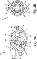
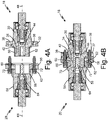
- FIG. 2A is a perspective view of first electrical connector 18.
- FIG. 2B is a front view of first electrical connector 18.
- FIG. 3A is a perspective view of second electrical connector 20.
- FIG. 3B is a front view of second electrical connector 20.
- FIG. 4A is a cross-sectional view of first electrical connector 18 and second electrical connector 20 disconnected.
- FIG. 4B is a cross-sectional view of first electrical connector 18 and second electrical connector 20 connected.
- FIGS. 2A-4B will be discussed together.
- first electrical connector 18 includes first body 30, first flange 32, first key 34, first threaded insert 36, second threaded insert 38, first end face 40, first seal 42, first metallic connector 44, and first aperture 46.
- First body 30 is the main body portion of first electrical connector 18 that the other components of first electrical connector 18 are coupled.
- First flange 32 is positioned adjacent first body 30 and first flange 32 extends radially outward from first body 30.
- First flange 32 includes apertures extending through first flange 32, in which first threaded insert 36 and second threaded insert 38 are positioned.
- First threaded insert 36 and second threaded insert 38 are configured to accept and mate with fasteners, discussed further below.
- First end face 40 of first key 34 is positioned at a distal end of first key 34.
- First seal 42 is positioned adjacent the location in which first key 34 interfaces with first flange 32 and first seal 42 surrounds a circumference of first key 34.
- First seal 42 is configured to prevent debris from entering first electrical connector 18 when first electrical connector 18 is connected to second electrical connector 20.
- first seal 42 is an O-ring seal, but in another example, first seal 42 can be any component that prevents debris from entering first electrical connector 18 when first electrical connector 18 is connected to second electrical connector 20.
- First end face 40 is configured to cover first metallic connector 44, preventing a user from touching first metallic connector 44.
- First metallic connector 44 is a female connector positioned within first body 30 and first key 34 of first electrical connector 18.
- First metallic connector 44 is the component that electrically couples first electrical connector 18 to second electrical connector 20, allowing electric current to transfer between each connector 18, 20.
- a user touching first metallic connector 44 and second metallic connector 64 of second electrical connector 20 at the same time can result in an electrical circuit being completed, which could shock or harm the user.
- first end face 40 is configured to prevent the user from touching first metallic connector 44 and harming themselves during connecting or disconnecting of first electrical connector 18 and second electrical connector 20.
- First aperture 46 is axially aligned with first axis 48 and first aperture 46 extends through first end face 40.
- second electrical connector 20 includes second body 54, second flange 56, second key 58, first fastener 60, second fastener 62, second metallic connector 64, and second aperture 66.
- Second body 54 is the main body portion of second electrical connector 20 that the other components of second electrical connector 20 are coupled.
- Second flange 56 is positioned adjacent second body 54 and second flange 56 extends radially outward from second body 54.
- Second flange 56 includes apertures extending through second flange 56, in which first fastener 60 and second fastener 62 are positioned.
- First fastener 60 and second fastener 62 are configured to mate with first threaded insert 36 and second threaded insert 38 of first electrical connector 18, respectively.
- First fastener 60 is positioned 180 degrees from second fastener 62 about second axis 68.
- Second key 58 is positioned within second flange 56 and second body 54. More specifically, second key 58 extends axially inward into second flange 56 and second body 54, with respect to second axis 68 extending through a center of second flange 56 and second body 54. Second key 58 is generally cylindrical in shape and includes first protrusion 70 and second protrusion 72 extending inward toward second axis 68. In the example shown, first protrusion 70 and second protrusion 72 include an arc or partial circle shaped protrusion extending inward from the cylindrically shaped second key 58. In another example, first protrusion 70 and second protrusion 72 can have any desired shape, as long as first protrusion 70 and second protrusion 72 have identical shaped geometry. First protrusion 70 is positioned 180 degrees from second protrusion 72 about second axis 68.
- Second aperture 66 is axially aligned with second axis 68 and second aperture 66 extends into second body 54. Second aperture 66 provides a location in which second metallic connector 64 can be coupled. Second metallic connector 64 is a male connector positioned within second aperture 66 of second body 54 and second key 58 of second electrical connector 20. Second metallic connector 64 is the component that electrically couples second electrical connector 20 to first electrical connector 18, allowing electric current to transfer between each connector. More specifically, second metallic connector 64 of second electrical connector 20 is inserted into first metallic connector 44 of first electrical connector 18 to complete an electric circuit and to transfer electric current between first electrical connector 18 and second electrical connector 20. Second electrical connector 20 is configured to mate with and be coupled to first electrical connector 18 during operation of heated hose assembly 10, discussed further below.
- first electrical connector 18 is shown disconnected from second electrical connector 20 ( FIG. 4A ) and first electrical connector 18 is shown connected to second electrical connector 20 ( FIG. 4B ).
- first electrical connector 18 is disconnected from second electrical connector 20
- the features and/or components of first electrical connector 18 are separated from second electrical connector 20 such that no electrical current is transferring between the connectors.
- first electrical connector 18 is connected to second electrical connector 20
- the features and/or components of first electrical connector 18 are contacting the features and/or components of second electrical connector 20 such that electrical current can transfer between the connectors.
- first flange 32 is adjacent and abuts second flange 56.
- First fastener 60 is inserted into and secured to first threaded insert 36 and second fastener 62 is inserted into and secured to second threaded insert 38.
- Securing fasteners 60, 62 to threaded inserts 36, 38 ensures that first electrical connector 18 and second electrical connector 20 will remain secured together during operation of heated hose assembly 10.
- First seal 42 is positioned and compressed between first flange 32 and second flange 56, producing a force that pushes first flange 32 and second flange 56 away from each other. The force produced by first seal 42 causes first fastener 60 and second fastener 62 to become tensioned, ensuring first fastener 60 and second fastener 62 remain secured to first threaded insert 36 and second threaded insert 38, respectively.
- first metallic connector 44 slides over and engages second metallic connector 64 such that first metallic connector 44 encompasses second metallic connector 64.
- the engagement of first metallic connector 44 and second metallic connector 64 creates an electric path, allowing electric current to transfer from first electrical connector 18 to second electrical connector 20, or vice versa.
- first key 34 is shaped to mate with second key 58 and first key 34 is inserted into second key 58. More specifically, first cutout 50 of first electrical connector 18 is shaped to accept first protrusion 70 of second electrical connector 20. Likewise, second cutout 52 of first electrical connector 18 is shaped to accept second protrusion 72 of second electrical connector 20.
- first cutout 50 is identical to second cutout 52 and the geometry of first protrusion 70 is identical to second protrusion 72.
- first electrical connector 18 can be rotated 180 degrees about first axis 48 and first electrical connector 18 and second electrical connector 20 can still mate and connect.
- first cutout 50 of first electrical connector 18 can accept second protrusion 72 of second electrical connector 20
- second cutout 52 of first electrical connector 18 can accept first protrusion 70 of second electrical connector 20.
- First key 34 and second key 58 have mating first cutout 50, second cutout 52, first protrusion 70, and second protrusion 72, ensuring that first electrical connector 18 and second electrical connector 20 are correctly connected to each other and the full amount of electrical current can transfer through connectors 18, 20.
- FIG. 5A is a perspective view of third electrical connector 22.
- FIG. 5B is a front view of third electrical connector 22.
- FIG. 6A is a perspective view of fourth electrical connector 24.
- FIG. 6B is a front view of fourth electrical connector 24.
- FIG. 7A is a cross-sectional view of third electrical connector 22 and fourth electrical connector 24 disconnected.
- FIG. 7B is a cross-sectional view of third electrical connector 22 and fourth electrical connector 24 connected.
- FIGS. 5A-7B will be discussed together.
- third electrical connector 22 includes third body 74, third flange 76, third key 78, third threaded insert 80, fourth threaded insert 82, third end face 84, second seal 86, third metallic connector 88, and third aperture 90.
- Third body 74 is the main body portion of third electrical connector 22 that the other components of third electrical connector 22 are coupled.
- Third flange 76 is positioned adjacent third body 74 and third flange 76 extends radially outward from third body 74.
- Third flange 76 includes apertures extending through third flange 76, in which third threaded insert 80 and fourth threaded insert 82 are positioned.
- Third key 78 is positioned adjacent third flange 76 and third key 78 extends axially outward from third flange 76 and third body 74, with respect to third axis 92 extending through a center of third flange 76 and third body 74.
- Third key 78 is generally cylindrical in shape and includes third cutout 94 and fourth cutout 96 extending from third end face 84 of third key 78 to third flange 76.
- third cutout 94 and fourth cutout 96 include a generally triangular shaped cutout extending into the cylindrically shaped third key 78.
- third cutout 94 and fourth cutout 96 can have any desired shape, as long as third cutout 94 and fourth cutout 96 have identical shaped geometry.
- Third cutout 94 is positioned 180 degrees from fourth cutout 96 about third axis 92.
- Third end face 84 of third key 78 is positioned at a distal end of third key 78.
- Second seal 86 is positioned adjacent the location in which third key 78 interfaces with third flange 76 and second seal 86 surrounds a circumference of third key 78.
- Second seal 86 is configured to prevent debris from entering third electrical connector 22 when third electrical connector 22 is connected to fourth electrical connector 24.
- second seal 86 is an O-ring seal, but in another example, second seal 86 can be any component that prevents debris from entering third electrical connector 22 when third electrical connector 22 is connected to fourth electrical connector 24.
- Third end face 84 is configured to cover third metallic connector 88, preventing a user from touching third metallic connector 88.
- Third metallic connector 88 is a female connector positioned within third body 74 and third key 78 of third electrical connector 22.
- Third metallic connector 88 is the component that electrically couples third electrical connector 22 to fourth electrical connector 24, allowing electric current to transfer between each connector.
- a user touching third metallic connector 88 and fourth metallic connector 108 of fourth electrical connector 24 at the same time can result in an electrical circuit being completed, which could shock or harm the user.
- third end face 84 is configured to prevent the user from touching third metallic connector 88 and harming themselves during connecting or disconnecting of third electrical connector 22 and fourth electrical connector 24.
- Third aperture 90 is axially aligned with third axis 92 and third aperture 90 extends through third end face 84. Third aperture 90 allows access to third metallic connector 88, allowing fourth metallic connector 108 of fourth electrical connector 24 to interface with third metallic connector 88, discussed further below. Third electrical connector 22 is configured to mate with fourth electrical connector 24 to complete an electrical circuit, allowing electric current to transfer from third electrical connector 22 to fourth electrical connector 24. Further, third electrical connector 22 is symmetric about a plane extending through a center axis of third threaded insert 80 and a center axis of fourth threaded insert 82, allowing third electrical connector 22 to be rotated 180 degrees about third axis 92 and still mate and couple with fourth electrical connector 24.
- fourth electrical connector 24 includes fourth body 98, fourth flange 100, fourth key 102, third fastener 104, fourth fastener 106, fourth metallic connector 108, and fourth aperture 110.
- Fourth body 98 is the main body portion of fourth electrical connector 24 that the other components of fourth electrical connector 24 are coupled.
- Fourth flange 100 is positioned adjacent fourth body 98 and fourth flange 100 extends radially outward from fourth body 98.
- Fourth flange 100 includes apertures extending through fourth flange 100, in which third fastener 104 and fourth fastener 106 are positioned.
- Third fastener 104 and fourth fastener 106 are configured to mate with third threaded insert 80 and fourth threaded insert 82 of third electrical connector 22, respectively.
- Third fastener 104 is positioned 180 degrees from fourth fastener 106 about fourth axis 112.
- Fourth key 102 is positioned within fourth flange 100 and fourth body 98. More specifically, fourth key 102 extends axially inward into fourth flange 100 and fourth body 98, with respect to fourth axis 112 extending through a center of fourth flange 100 and fourth body 98. Fourth key 102 is generally cylindrical in shape and includes third protrusion 114 and fourth protrusion 116 extending inward toward fourth axis 112. In the example shown, third protrusion 114 and fourth protrusion 116 include a generally triangular shaped protrusion extending inward from the cylindrically shaped fourth key 102.
- third protrusion 114 and fourth protrusion 116 can have any desired shape, as long as third protrusion 114 and fourth protrusion 116 have identical shaped geometry.
- Third protrusion 114 is positioned 180 degrees from fourth protrusion 116 about fourth axis 112.
- Fourth aperture 110 is axially aligned with fourth axis 112 and fourth aperture 110 extends into fourth body 98.
- Fourth aperture 110 provides a location in which fourth metallic connector 108 can be coupled.
- Fourth metallic connector 108 is a male connector positioned within fourth aperture 110 of fourth body 98 and fourth key 102 of fourth electrical connector 24.
- Fourth metallic connector 108 is the component that electrically couples fourth electrical connector 24 to third electrical connector 22, allowing electric current to transfer between each connector. More specifically, fourth metallic connector 108 of fourth electrical connector 24 is inserted into third metallic connector 88 of third electrical connector 22 to complete an electric circuit and to transfer electric current between third electrical connector 22 and fourth electrical connector 24.
- Fourth electrical connector 24 is configured to mate with and be coupled to third electrical connector 22 during operation of heated hose assembly 10, discussed further below.
- fourth electrical connector 24 is symmetric about a plane extending through a center axis of third fastener 104 and a center axis of fourth fastener 106, allowing fourth electrical connector 24 to be rotated 180 degrees about fourth axis 112 and still mate and couple with third electrical connector 22.
- third flange 76 is adjacent and abuts fourth flange 100.
- Third fastener 104 is inserted into and secured to third threaded insert 80 and fourth fastener 106 is inserted into and secured to fourth threaded insert 82.
- Securing fasteners 60, 62 to threaded inserts 36, 38 ensures that third electrical connector 22 and fourth electrical connector 24 will remain secured together during operation of heated hose assembly 10.
- Second seal 86 is positioned and compressed between third flange 76 and fourth flange 100, producing a force that pushes third flange 76 and fourth flange 100 away from each other. The force produced by second seal 86 causes third fastener 104 and fourth fastener 106 to become tensioned, ensuring third fastener 104 and fourth fastener 106 remain secured to third threaded insert 80 and fourth threaded insert 82, respectively.
- third metallic connector 88 slides over and engages fourth metallic connector 108 such that third metallic connector 88 encompasses fourth metallic connector 108.
- the engagement of third metallic connector 88 and fourth metallic connector 108 creates an electric path, allowing electric current to transfer from third electrical connector 22 to fourth electrical connector 24, or vice versa.
- third key 78 is shaped to mate with fourth key 102 and third key 78 is inserted into fourth key 102. More specifically, third cutout 94 of third electrical connector 22 is shaped to accept third protrusion 114 of fourth electrical connector 24. Likewise, fourth cutout 96 of third electrical connector 22 is shaped to accept fourth protrusion 116 of fourth electrical connector 24.
- third cutout 94 is identical to fourth cutout 96 and the geometry of third protrusion 114 is identical to fourth protrusion 116.
- third electrical connector 22 can be rotated 180 degrees about third axis 92 and third electrical connector 22 and fourth electrical connector 24 can still mate and connect.
- third cutout 94 of third electrical connector 22 can accept fourth protrusion 116 of fourth electrical connector 24 and fourth cutout 96 of third electrical connector 22 can accept third protrusion 114 of fourth electrical connector 24.
- Third key 78 and fourth key 102 have mating third cutout 94, fourth cutout 96, third protrusion 114, and fourth protrusion 116, ensuring that third electrical connector 22 and fourth electrical connector 24 are correctly connected to each other and the full amount of electrical current can flow through connectors 22, 24.
- first key 34 of first electrical connector 18 is configured to mate with second key 58 of second electrical connector 20. More specifically, first cutout 50 and second cutout 52 of first electrical connector 18 are shaped to mate with first protrusion 70 and second protrusion 72 of second electrical connector 20. Likewise, third key 78 of third electrical connector 22 is configured to mate with fourth key 102 of fourth electrical connector 24. More specifically, third cutout 94 and fourth cutout 96 of third electrical connector 22 are shaped to mate with third protrusion 114 and fourth protrusion 116 of fourth electrical connector 24. Therefore, first key 34, second key 58, third key 78, and fourth key 102 ensure first electrical connector 18 and second electrical connector 20 are correctly connected, and ensure third electrical connector 22 and fourth electrical connector 24 are correctly connected. Further, first key 34, second key 58, third key 78, and fourth key 102 prevent first electrical connector 18 from connecting with fourth electrical connector 24, and prevent third electrical connector 22 from connecting with second electrical connector 20.
- First electrical connector 18 includes first key 34 with a geometry that differs from the geometry of third key 78 of third electrical connector 22. Further, first electrical connector 18 includes first key 34 with a geometry that cannot mate with the geometry of fourth key 102 of fourth electrical connector 24. More specifically, first cutout 50 and second cutout 52 of first electrical connector 18 include a geometry that does not conform and mate with third protrusion 114 and fourth protrusion 116 of fourth electrical connector 24. As such, first key 34 and fourth key 102 cannot be connected, preventing first electrical connector 18 and fourth electrical connector 24 from being electrically coupled. Similarly, third electrical connector 22 includes third key 78 with a geometry that differs from the geometry of first key 34 of first electrical connector 18.
- third electrical connector 22 includes third key 78 with a geometry that cannot mate with the geometry of second key 58 of second electrical connector 20. More specifically, third cutout 94 and fourth cutout 96 of third electrical connector 22 include a geometry that does not conform and mate with first protrusion 70 and second protrusion 72 of second electrical connector 20. As such, third key 78 and second key 58 cannot be connected, preventing third electrical connector 22 and second electrical connector 20 from being electrically coupled.
- Electrical connectors 18, 20, 22, and 24 including keys 34, 58, 78, and 102, respectively, ensure that electrical connector system 12 of heated hose assembly 10 is connected correctly. In turn, this ensure that electrical current and power is supplied to sufficiently heat first heated hose 14 and second heated hose 16.
- the geometry of keys 34, 58, 78, and 102 allows a user to easily and repeatedly connect electrical connectors 18, 20, 22, and 24. Further, first end face 40 and third end face 84 prevent a user from touching first metallic connector 44 and third electrical connector 22, preventing a user from completing the electrical circuit and electrocuting themselves or others.
- first threaded insert 36, second threaded insert 38, first fastener 60, and second fastener 62 ensure connectors 18, 20, 22, and 24 remain secured together during operation of heated hose assembly 10, providing electric current to first heated hose 14 and second heated hose 16.
- Electrical connectors 18, 20, 22, and 24 can be constructed from one or more of a glass filled nylon, a glass filled plastic, and other composite materials, to meet nationally recognized safety and sustainability standards. Electrical connectors 18, 20, 22, and 24 include keys 34, 58, 78, and 102, respectively, including different mating geometries, ensuring connectors 18, 20, 22, and 24 can only be connected in the correct configuration to provide the requisite electrical current and power to the independently heated first heated hose 14 and second heated hose 16.
- Heated hose assembly 10 utilizes electrical connector system 12 to increase the temperature of the first fluid component and the second fluid component flowing through the conduits of first heated hose 14 and second heated hose 16, respectively.
- An example method of operating heated hose assembly 10 can include providing first heated hose 14 configured to transfer a first fluid component, first heated hose 14 comprising first electrical connector 18 and second electrical connector 20 each electrically coupled to heating elements of first heated hose 14.
- third electrical connector 22 Electrically coupling third electrical connector 22 to fourth electrical connector 24 such that third key 78 of third electrical connector 22 mates with fourth key 102 of fourth electrical connector 24.
- the method can further include providing first threaded insert 36 and second threaded insert 38 within first flange 32 of first electrical connector 18.
- An electrical connector system comprising: a first electrical connector comprising a first key; a second electrical connector comprising a second key shaped to mate with the first key; a third electrical connector comprising a third key; and a fourth electrical connector comprising a fourth key shaped to mate with the third key; wherein a geometry of the first key differs from a geometry of the third key, and wherein a geometry of the second key differs from a geometry of the fourth key.
- the electrical connector system of the preceding paragraph can optionally include, additionally and/or alternatively, any one or more of the following features, configurations and/or additional components:
- the first electrical connector is a male connector and the second electrical connector is a female connector, and wherein the first electrical connector is configured to mate and connect with the second electrical connector.
- the third electrical connector is a male connector and the fourth electrical connector is a female connector, and wherein the third electrical connector is configured to mate and connect with the fourth electrical connector.
- the first electrical connector further comprises a first body and a first flange extending radially outward from the first body; and the second electrical connector further comprises a second body and a second flange extending radially outward from the second body.
- a first threaded insert and a second threaded insert are positioned within the first flange of the first electrical connector; and a first fastener and a second fastener are positioned within and extend through the second flange of the second electrical connector.
- the first threaded insert is coupled to the first fastener when the first electrical connector and the second electrical connector are connected; and the second threaded insert is coupled to the second fastener when the first electrical connector and the second electrical connector are connected.
- a third threaded insert and a fourth threaded insert are positioned within the third flange of the third electrical connector; and a third fastener and a fourth fastener are positioned within and extend through the fourth flange of the fourth electrical connector.
- the third threaded insert is coupled to the third fastener when the third electrical connector and the fourth electrical connector are connected; and the fourth threaded insert is coupled to the fourth fastener when the third electrical connector and the fourth electrical connector are connected.
- the first key comprises a first cutout and a second cutout extending from a first end face of the first electrical connector to a first flange of the first electrical connector; and the second key comprises a first protrusion and a second protrusion extending into a second aperture of a second body of the second electrical connector.
- the first cutout is positioned 180 degrees from the second cutout about a first axis extending through a first aperture of the first electrical connector; and the first protrusion is positioned 180 degrees from the second protrusion about a second axis extending through the second aperture of the second electrical connector.
- the first cutout includes a geometry identical to the second cutout; the first protrusion includes a geometry identical to the second protrusion; the first cutout is shaped to accept the first protrusion and the second cutout is shaped to accept the second protrusion; and the first cutout is shaped to accept the second protrusion and the second cutout is shaped to accept the first protrusion.
- the third key comprises a third cutout and a fourth cutout extending from a third end face of the third electrical connector to a third flange of the third electrical connector; and the fourth key comprises a third protrusion and a fourth protrusion extending into a fourth aperture of a fourth body of the fourth electrical connector.
- the third cutout is positioned 180 degrees from the fourth cutout about a third axis extending through a third aperture of the third electrical connector; and the third protrusion is positioned 180 degrees from the fourth protrusion about a fourth axis extending through the fourth aperture of the fourth electrical connector.
- the third cutout includes a geometry identical to the fourth cutout; the third protrusion includes a geometry identical to the fourth protrusion; the third cutout is shaped to accept the third protrusion and the fourth cutout is shaped to accept the fourth protrusion; and the third cutout is shaped to accept the fourth protrusion and the fourth cutout is shaped to accept the third protrusion.
- the geometry of the first cutout differs from the third cutout and the fourth cutout; the geometry of the second cutout differs from the third cutout and the fourth cutout; the geometry of the first protrusion differs from the third protrusion and the fourth protrusion; and the geometry of the second protrusion differs from the third protrusion and the fourth protrusion.
- a heated hose assembly comprising: a first heated hose configured to transfer a first fluid component; a second heated hose configured to transfer a second fluid component; a first electrical connector electrically coupled to heating elements of the first heated hose, the first electrical connector comprising a first key; a second electrical connector electrically coupled to heating elements of the first heated hose, the second electrical connector comprising a second key shaped to mate with the first key; a third electrical connector electrically coupled to heating elements of the second heated hose, the third electrical connector comprising a third key; a fourth electrical connector electrically coupled to heating elements of the second heated hose, the fourth electrical connector comprising a fourth key shaped to mate with the third key.
- the heated hose assembly of the preceding paragraph can optionally include, additionally and/or alternatively, any one or more of the following features, configurations and/or additional components:
- the first electrical connector further comprises a first body, a first flange extending radially outward from the first body, a first threaded insert positioned within the first flange, and a second threaded insert positioned within the flange; and the second electrical connector further comprises a second body, a second flange extending radially outward from the second body, a first fastener extending through the second flange, and a second fastener extending through the second flange.
- the first electrical connector is symmetric about a plane extending through a center axis of the first threaded insert and a center axis of the second threaded insert; and the second electrical connector is symmetric about a plane extending through a center axis of the first fastener and a center axis of the second fastener.
- the first key of the first electrical connector comprises a first cutout and a second cutout having identical geometry;
- the second key of the second electrical connector comprises a first protrusion and a second protrusion having identical geometry;
- the third key of the third electrical connector comprises a third cutout and a fourth cutout having identical geometry;
- the fourth key of the fourth electrical connector comprises a third protrusion and a fourth protrusion having identical geometry;
- the first cutout is shaped to accept the first protrusion and the second cutout is shaped to accept the second protrusion;
- the third cutout is shaped to accept the third protrusion and the fourth cutout is shaped to accept the fourth protrusion;
- the geometry of the first cutout differs from the geometry of the third cutout and the geometry of fourth cutout; and the geometry of the first protrusion differs from the geometry of the third protrusion and the geometry of the fourth protrusion.
- a method of operating a heated hose assembly comprising: providing a first heated hose configured to transfer a first fluid component, the first heated hose comprising a first electrical connector and a second electrical connector each electrically coupled to heating elements of the first heated hose; providing a second heated hose configured to transfer a second fluid component, the second heated hose comprising a third electrical connector and a fourth electrical connector each electrically coupled to heating elements of the second heated hose; electrically coupling the first electrical connector to the second electrical connector such that a first key of the first electrical connector mates with a second key of the second electrical connector; electrically coupling the third electrical connector to the fourth electrical connector such that a third key of the third electrical connector mates with a fourth key of the fourth electrical connector; supplying a first electric current through the first electrical connector and the second electrical connector to increase a temperature of the first fluid component transferring through the first heated hose; and supplying a second electric current through the third electrical connector and the fourth electrical connector to increase a temperature of the second fluid component transferring through the second heated
- the method of the preceding paragraph can optionally include, additionally and/or alternatively, any one or more of the following features, configurations and/or additional components: Providing a first threaded insert and a second threaded insert within a first flange of the first electrical connector; providing a first fastener and a second fastener extending through a second flange of the second electrical connector; threading the first fastener and the second fastener into the first threaded insert and the second threaded insert, respectively, to couple the first electrical connector to the second electrical connector; providing a third threaded insert and a fourth threaded insert within a third flange of the third electrical connector; providing a third fastener and a fourth fastener extending through a fourth flange of the fourth electrical connector; and threading the third fastener and the fourth fastener into the third threaded insert and the fourth threaded insert, respectively, to couple the third electrical connector to the fourth electrical connector.
Landscapes
- Engineering & Computer Science (AREA)
- General Engineering & Computer Science (AREA)
- Mechanical Engineering (AREA)
- Manufacturing & Machinery (AREA)
- Connector Housings Or Holding Contact Members (AREA)
- Pipe Accessories (AREA)
- Quick-Acting Or Multi-Walled Pipe Joints (AREA)
- Control Of Resistance Heating (AREA)
- Joints That Cut Off Fluids, And Hose Joints (AREA)
Abstract
Description
- The present disclosure relates generally to electrical connectors, and more particularly to keyed electrical connectors used with electrically heated hoses of a plural component (e.g. fluid) dispensing system.
- Multiple component (e.g., fluid) applicators include dispensing systems that receive separate inert material components, mix the components according to a predetermined ratio, and then dispense the components as an activated compound. For example, multiple component applicators are often used to dispense epoxies and polyurethanes that solidify after mixing of a resin component and an activating component, which are individually inert. Some dispensing systems include electrically heated hoses that increase the temperature of the material components flowing through each hose to a desired temperature, ensuring a proper activated mixture is achieved. The electrically heated hoses include electrical connectors that are used to electrically couple each heated hose segment to an electrical power source. Incorrectly connecting the electrical connectors can result in a decreased amount of electrical current supplied to the heated hoses, resulting in decreased performance of the electrically heated hoses.
- According to one aspect of the disclosure, an electrical connector system includes a first electrical connector, a second electrical connector, and third electrical connector, and a fourth electrical connector. The first electrical connector includes a first key. The second electrical connector includes a second key shaped to mate with the first key. The third electrical connector includes a third key. The fourth electrical connector includes a fourth key shaped to mate with the third key. The geometry of the first key differs from the geometry of the third key, and the geometry of the second key differs from the geometry of the fourth key.
- According to another aspect of the disclosure, a heated hose assembly includes a first heated hose, a second heated hose, a first electrical connector, a second electrical connector, and third electrical connector, and a fourth electrical connector. The first heated hose is configured to transfer a first fluid component. The second heated hose is configured to transfer a second fluid component. The first electrical connector is electrically coupled to heating elements of the first heated hose, and the first electrical connector includes a first key. The second electrical connector is electrically coupled to heating elements of the first heated hose, and the second electrical connector includes a second key shaped to mate with the first key. The third electrical connector is electrically coupled to heating elements of the second heated hose, and the third electrical connector includes a third key. The fourth electrical connector is electrically coupled to heating elements of the second heated hose, and the fourth electrical connector includes a fourth key shaped to mate with the third key.
- According to yet another aspect of the disclosure, a method of operating a heated hose assembly is disclosed. The method includes: providing a first heated hose configured to transfer a first fluid component, the first heated hose comprising a first electrical connector and a second electrical connector each electrically coupled to heating elements of the first heated hose; providing a second heated hose configured to transfer a second fluid component, the second heated hose comprising a third electrical connector and a fourth electrical connector each electrically coupled to heating elements of the second heated hose; electrically coupling the first electrical connector to the second electrical connector such that a first key of the first electrical connector mates with a second key of the second electrical connector; electrically coupling the third electrical connector to the fourth electrical connector such that a third key of the third electrical connector mates with a fourth key of the fourth electrical connector; supplying a first electric current through the first electrical connector and the second electrical connector to increase a temperature of the first fluid component transferring through the first heated hose; and supplying a second electric current through the third electrical connector and the fourth electrical connector to increase a temperature of the second fluid component transferring through the second heated hose.
- According to an aspect of the present invention, there is provided an electrical connector system comprising: a first electrical connector comprising a first key; a second electrical connector comprising a second key shaped to mate with the first key; a third electrical connector comprising a third key; and a fourth electrical connector comprising a fourth key shaped to mate with the third key; wherein a geometry of the first key differs from a geometry of the third key, and wherein a geometry of the second key differs from a geometry of the fourth key.
- Preferably, the first electrical connector is a male connector and the second electrical connector is a female connector; the first electrical connector is configured to mate and connect with the second electrical connector; the third electrical connector is a male connector and the fourth electrical connector is a female connector; and the third electrical connector is configured to mate and connect with the fourth electrical connector.
- Preferably, the first electrical connector further comprises a first body and a first flange extending radially outward from the first body; and the second electrical connector further comprises a second body and a second flange extending radially outward from the second body.
- Preferably, a first threaded insert and a second threaded insert are positioned within the first flange of the first electrical connector; and a first fastener and a second fastener are positioned within and extend through the second flange of the second electrical connector.
- Preferably, the first threaded insert is coupled to the first fastener when the first electrical connector and the second electrical connector are connected; and the second threaded insert is coupled to the second fastener when the first electrical connector and the second electrical connector are connected.
- Preferably, the third electrical connector further comprises a third body and a third flange extending radially outward from the third body; and the fourth electrical connector further comprises a fourth body and a fourth flange extending radially outward from the fourth body.
- Preferably, a third threaded insert and a fourth threaded insert are positioned within the third flange of the third electrical connector; and a third fastener and a fourth fastener are positioned within and extend through the fourth flange of the fourth electrical connector.
- Preferably, the third threaded insert is coupled to the third fastener when the third electrical connector and the fourth electrical connector are connected; and the fourth threaded insert is coupled to the fourth fastener when the third electrical connector and the fourth electrical connector are connected.
- Preferably, the first key comprises a first cutout and a second cutout extending from a first end face of the first electrical connector to a first flange of the first electrical connector; and the second key comprises a first protrusion and a second protrusion extending into a second aperture of a second body of the second electrical connector.
- Preferably, the first cutout is positioned 180 degrees from the second cutout about a first axis extending through a first aperture of the first electrical connector; and the first protrusion is positioned 180 degrees from the second protrusion about a second axis extending through the second aperture of the second electrical connector.
- Preferably, the first cutout includes a geometry identical to the second cutout; the first protrusion includes a geometry identical to the second protrusion; the first cutout is shaped to accept the first protrusion and the second cutout is shaped to accept the second protrusion; and the first cutout is shaped to accept the second protrusion and the second cutout is shaped to accept the first protrusion.
- Preferably, the third key comprises a third cutout and a fourth cutout extending from a third end face of the third electrical connector to a third flange of the third electrical connector; and the fourth key comprises a third protrusion and a fourth protrusion extending into a fourth aperture of a fourth body of the fourth electrical connector.
- Preferably, the third cutout is positioned 180 degrees from the fourth cutout about a third axis extending through a third aperture of the third electrical connector; and the third protrusion is positioned 180 degrees from the fourth protrusion about a fourth axis extending through the fourth aperture of the fourth electrical connector.
- Preferably, the third cutout includes a geometry identical to the fourth cutout; the third protrusion includes a geometry identical to the fourth protrusion; the third cutout is shaped to accept the third protrusion and the fourth cutout is shaped to accept the fourth protrusion; and the third cutout is shaped to accept the fourth protrusion and the fourth cutout is shaped to accept the third protrusion.
- Preferably, the geometry of the first cutout differs from the third cutout and the fourth cutout; the geometry of the second cutout differs from the third cutout and the fourth cutout; the geometry of the first protrusion differs from the third protrusion and the fourth protrusion; and the geometry of the second protrusion differs from the third protrusion and the fourth protrusion.
- According to another aspect of the present invention, there is provided a heated hose assembly comprising: a first heated hose configured to transfer a first fluid component; a second heated hose configured to transfer a second fluid component; a first electrical connector electrically coupled to heating elements of the first heated hose, the first electrical connector comprising a first key; a second electrical connector electrically coupled to heating elements of the first heated hose, the second electrical connector comprising a second key shaped to mate with the first key; a third electrical connector electrically coupled to heating elements of the second heated hose, the third electrical connector comprising a third key; a fourth electrical connector electrically coupled to heating elements of the second heated hose, the fourth electrical connector comprising a fourth key shaped to mate with the third key.
- Preferably, the first electrical connector further comprises a first body, a first flange extending radially outward from the first body, a first threaded insert positioned within the first flange, and a second threaded insert positioned within the flange; and the second electrical connector further comprises a second body, a second flange extending radially outward from the second body, a first fastener extending through the second flange, and a second fastener extending through the second flange.
- Preferably, the first electrical connector is symmetric about a plane extending through a center axis of the first threaded insert and a center axis of the second threaded insert; and the second electrical connector is symmetric about a plane extending through a center axis of the first fastener and a center axis of the second fastener.
- Preferably, the first key of the first electrical connector comprises a first cutout and a second cutout having identical geometry; the second key of the second electrical connector comprises a first protrusion and a second protrusion having identical geometry; the third key of the third electrical connector comprises a third cutout and a fourth cutout having identical geometry; the fourth key of the fourth electrical connector comprises a third protrusion and a fourth protrusion having identical geometry; the first cutout is shaped to accept the first protrusion and the second cutout is shaped to accept the second protrusion; the third cutout is shaped to accept the third protrusion and the fourth cutout is shaped to accept the fourth protrusion; the geometry of the first cutout differs from the geometry of the third cutout and the geometry of fourth cutout; and the geometry of the first protrusion differs from the geometry of the third protrusion and the geometry of the fourth protrusion.
- According to a further aspect of the present invention, there is provided a method of operating a heated hose assembly, the method comprising: providing a first heated hose configured to transfer a first fluid component, the first heated hose comprising a first electrical connector and a second electrical connector each electrically coupled to heating elements of the first heated hose; providing a second heated hose configured to transfer a second fluid component, the second heated hose comprising a third electrical connector and a fourth electrical connector each electrically coupled to heating elements of the second heated hose; electrically coupling the first electrical connector to the second electrical connector such that a first key of the first electrical connector mates with a second key of the second electrical connector; electrically coupling the third electrical connector to the fourth electrical connector such that a third key of the third electrical connector mates with a fourth key of the fourth electrical connector; supplying a first electric current through the first electrical connector and the second electrical connector to increase a temperature of the first fluid component transferring through the first heated hose; and supplying a second electric current through the third electrical connector and the fourth electrical connector to increase a temperature of the second fluid component transferring through the second heated hose.
-
-
FIG. 1 is a perspective view of a heated hose assembly including an electrical connector system. -
FIG. 2A is a perspective view of a first electrical connector. -
FIG. 2B is a front view of the first electrical connector. -
FIG. 3A is a perspective view of a second electrical connector. -
FIG. 3B is a front view of the second electrical connector. -
FIG. 4A is a cross-sectional view of the first and second electrical connectors disconnected. -
FIG. 4B is a cross-sectional view of the first and second electrical connectors connected. -
FIG. 5A is a perspective view of a third electrical connector. -
FIG. 5B is a front view of the third electrical connector. -
FIG. 6A is a perspective view of a fourth electrical connector. -
FIG. 6B is a front view of the fourth electrical connector. -
FIG. 7A is a cross-sectional view of the third and fourth electrical connectors disconnected. -
FIG. 7B is a cross-sectional view of the third and fourth electrical connectors connected. -
FIG. 1 is a perspective view ofheated hose assembly 10 includingelectrical connector system 12.Heated hose assembly 10 includes firstheated hose 14, secondheated hose 16, andelectrical connector system 12. In some examples,heated hose assembly 10 can be used with multiple component dispensing systems that receive separate inert material components, mix the components according to a predetermined ratio, and then dispense the components as an activated compound.Heated hose assembly 10 includes electrically heated hoses that are configured to increase the temperature of the material components flowing through each hose, ensuring a proper activated mixture is achieved. - More specifically, first
heated hose 14 and secondheated hose 16 are configured to transfer a first fluid component and a second fluid component, respectively, the first and second fluid components can be different from each other. Firstheated hose 14 and secondheated hose 16 are independently heated hoses that receive separate electrical power (e.g. electrical current) at the heating elements (e.g. wires) of eachheated hose heated hose 14 and secondheated hose 16. Independently heating firstheated hose 14 and secondheated hose 16 allows a greater power density to be achieved, providing increased heating capabilities for each of firstheated hose 14 and secondheated hose 16.Electrical connector system 12 is coupled to firstheated hose 14 and secondheated hose 16.Electrical connector system 12 is configured to electrically couple the heating elements of each heated hose segment to an electrical power source. -
Electrical connector system 12 includes firstelectrical connector 18, secondelectrical connector 20, thirdelectrical connector 22, and fourthelectrical connector 24. Firstelectrical connector 18 is electrically coupled toheating elements 14a of firstheated hose 14. Secondelectrical connector 20 is electrically coupled toheating elements 14a of firstheated hose 14. Thirdelectrical connector 22 is electrically coupled toheating elements 16a of secondheated hose 16. Fourthelectrical connector 24 is electrically coupled toheating elements 16a of secondheated hose 16. In some examples, firstelectrical connector 18, secondelectrical connector 20, andheating elements 14a can be referred to as the first sub-assembly ofheated hose assembly 10. Further, in some examples, thirdelectrical connector 22, fourthelectrical connector 24, andheating elements 16a can be referred to as the second sub-assembly ofheated hose assembly 10. The first and second sub-assemblies ofheated hose assembly 10 are configured to increase the temperature of the fluid components flowing through firstheated hose 14 and secondheated hose 16, respectively. - First
electrical connector 18 is a male connector and secondelectrical connector 20 is a female connector, and firstelectrical connector 18 is configured to mate and connect with secondelectrical connector 20. Thirdelectrical connector 22 is a male connector and fourthelectrical connector 24 is a female connector, and thirdelectrical connector 22 is configured to mate and connect with fourthelectrical connector 24. - More specifically, both first
electrical connector 18 and secondelectrical connector 20 include dual male/female connections. Firstelectrical connector 18 includes an inner female connector positioned at a central axis of firstelectrical connector 18 and an outer male connector positioned radially outward from the inner female connector. Secondelectrical connector 20 includes an inner male connector positioned at a central axis of secondelectrical connector 20 and an outer female connector positioned radially outward from the inner male connector. As such, the inner female connector of firstelectrical connector 18 is configured to mate with the inner male connector of secondelectrical connector 20. The outer male connector of firstelectrical connector 18 is configured to mate with the outer female connector of secondelectrical connector 20. In some examples, the first male/female connection can be structural (e.g., inner male connector of secondelectrical connector 20 and inner female connector of first electrical connector 18) and the second male/female connection can be electrical (e.g., outer female connector of secondelectrical connector 20 and outer male connector of first electrical connector 18). - Likewise, both third
electrical connector 22 and fourthelectrical connector 24 include dual male/female connections. Thirdelectrical connector 22 includes an inner female connector positioned at a central axis of thirdelectrical connector 22 and an outer male connector positioned radially outward from the inner female connector. Fourthelectrical connector 24 includes an inner male connector positioned at a central axis of fourthelectrical connector 24 and an outer female connector positioned radially outward from the inner male connector. As such, the inner female connector of thirdelectrical connector 22 is configured to mate with the inner male connector of fourthelectrical connector 24. The outer male connector of thirdelectrical connector 22 is configured to mate with the outer female connector of fourthelectrical connector 24. In some examples, the third male/female connection can be structural (e.g., outer female connector of fourthelectrical connector 24 and outer male connector of third electrical connector 22) and the fourth male/female connection can be electrical (e.g., inner male connector of fourthelectrical connector 24 and inner female connector of third electrical connector 22). - In the embodiment shown, first
heated hose 14 includes two of each of firstelectrical connector 18 and secondelectrical connector 20. Likewise, secondheated hose 16 includes two of each of thirdelectrical connector 22 and fourthelectrical connector 24. In another embodiment,heated hoses electrical connectors electrical connectors heated hose 14 or secondheated hose 16. - As shown in
FIG. 1 ,heated hose assembly 10 can include a plurality of heated hose segments that are connected to increase the overall length of firstheated hose 14 and secondheated hose 16. This allows a user to dispense the activated fluid component mixture at a location remote from the fluid component containers. Each of firstheated hose 14 and secondheated hose 16 includes fluid connectors at the distal ends of eachhose heated hose 14 and secondheated hose 16 includeelectrical connectors - More specifically, one segment of first
heated hose 14 includes firstelectrical connector 18 and another segment of firstheated hose 14 includes secondelectrical connector 20. Firstelectrical connector 18 and secondelectrical connector 20 are configured to mate and electrically connect, allowing electric current to transfer from one segment of firstheated hose 14 to another segment of firstheated hose 14. Similarly, one segment of secondheated hose 16 includes thirdelectrical connector 22 and another segment of secondheated hose 16 includes fourthelectrical connector 24. Thirdelectrical connector 22 and fourthelectrical connector 24 are configured to mate and electrically connect, allowing electric current to transfer from one segment of secondheated hose 16 to another segment of secondheated hose 16. As such,electrical connectors heated hose 14 and secondheated hose 16 to increase the temperature of firstheated hose 14 and secondheated hose 16. -
FIG. 2A is a perspective view of firstelectrical connector 18.FIG. 2B is a front view of firstelectrical connector 18.FIG. 3A is a perspective view of secondelectrical connector 20.FIG. 3B is a front view of secondelectrical connector 20.FIG. 4A is a cross-sectional view of firstelectrical connector 18 and secondelectrical connector 20 disconnected.FIG. 4B is a cross-sectional view of firstelectrical connector 18 and secondelectrical connector 20 connected.FIGS. 2A-4B will be discussed together. - Referring to
FIGS. 2A-2B , firstelectrical connector 18 includesfirst body 30,first flange 32, first key 34, first threadedinsert 36, second threadedinsert 38,first end face 40,first seal 42, firstmetallic connector 44, andfirst aperture 46.First body 30 is the main body portion of firstelectrical connector 18 that the other components of firstelectrical connector 18 are coupled.First flange 32 is positioned adjacentfirst body 30 andfirst flange 32 extends radially outward fromfirst body 30.First flange 32 includes apertures extending throughfirst flange 32, in which first threadedinsert 36 and second threadedinsert 38 are positioned. First threadedinsert 36 and second threadedinsert 38 are configured to accept and mate with fasteners, discussed further below. First threadedinsert 36 is positioned 180 degrees from second threadedinsert 38 aboutfirst axis 48. In some examples, first threadedinsert 36 and second threadedinsert 38 can be molded intofirst flange 32 during manufacturing of firstelectrical connector 18. In other examples, first threadedinsert 36 and second threadedinsert 38 can be coupled tofirst flange 32 after manufacturing of firstelectrical connector 18. - First key 34 is positioned adjacent
first flange 32 and first key 34 extends axially outward fromfirst flange 32 andfirst body 30, with respect tofirst axis 48 extending through a center offirst flange 32 andfirst body 30. First key 34 is generally cylindrical in shape and includesfirst cutout 50 andsecond cutout 52 extending fromfirst end face 40 of first key 34 tofirst flange 32. In the example shown,first cutout 50 andsecond cutout 52 include an arc or partial circle shaped cutout extending into the cylindrically shaped first key 34. In another example,first cutout 50 andsecond cutout 52 can have any desired shape, as long asfirst cutout 50 andsecond cutout 52 have identical shaped geometry.First cutout 50 is positioned 180 degrees fromsecond cutout 52 aboutfirst axis 48. First end face 40 of first key 34 is positioned at a distal end of first key 34.First seal 42 is positioned adjacent the location in which first key 34 interfaces withfirst flange 32 andfirst seal 42 surrounds a circumference of first key 34.First seal 42 is configured to prevent debris from entering firstelectrical connector 18 when firstelectrical connector 18 is connected to secondelectrical connector 20. In the example shown,first seal 42 is an O-ring seal, but in another example,first seal 42 can be any component that prevents debris from entering firstelectrical connector 18 when firstelectrical connector 18 is connected to secondelectrical connector 20. -
First end face 40 is configured to cover firstmetallic connector 44, preventing a user from touching firstmetallic connector 44. Firstmetallic connector 44 is a female connector positioned withinfirst body 30 andfirst key 34 of firstelectrical connector 18. Firstmetallic connector 44 is the component that electrically couples firstelectrical connector 18 to secondelectrical connector 20, allowing electric current to transfer between eachconnector metallic connector 44 and secondmetallic connector 64 of secondelectrical connector 20 at the same time can result in an electrical circuit being completed, which could shock or harm the user. As such,first end face 40 is configured to prevent the user from touching firstmetallic connector 44 and harming themselves during connecting or disconnecting of firstelectrical connector 18 and secondelectrical connector 20.First aperture 46 is axially aligned withfirst axis 48 andfirst aperture 46 extends throughfirst end face 40.First aperture 46 allows access to firstmetallic connector 44, allowing secondmetallic connector 64 of secondelectrical connector 20 to interface with firstmetallic connector 44, discussed further below. Firstelectrical connector 18 is configured to mate with secondelectrical connector 20 to complete an electrical circuit, allowing electric current to transfer from firstelectrical connector 18 to secondelectrical connector 20. Further, firstelectrical connector 18 is symmetric about a plane extending through a center axis of first threadedinsert 36 and a center axis of second threadedinsert 38, allowing firstelectrical connector 18 to be rotated 180 degrees aboutfirst axis 48 and still mate and couple with secondelectrical connector 20. - Referring to
FIGS. 3A-3B , secondelectrical connector 20 includessecond body 54,second flange 56, second key 58,first fastener 60,second fastener 62, secondmetallic connector 64, andsecond aperture 66.Second body 54 is the main body portion of secondelectrical connector 20 that the other components of secondelectrical connector 20 are coupled.Second flange 56 is positioned adjacentsecond body 54 andsecond flange 56 extends radially outward fromsecond body 54.Second flange 56 includes apertures extending throughsecond flange 56, in whichfirst fastener 60 andsecond fastener 62 are positioned.First fastener 60 andsecond fastener 62 are configured to mate with first threadedinsert 36 and second threadedinsert 38 of firstelectrical connector 18, respectively.First fastener 60 is positioned 180 degrees fromsecond fastener 62 aboutsecond axis 68. - Second key 58 is positioned within
second flange 56 andsecond body 54. More specifically, second key 58 extends axially inward intosecond flange 56 andsecond body 54, with respect tosecond axis 68 extending through a center ofsecond flange 56 andsecond body 54. Second key 58 is generally cylindrical in shape and includesfirst protrusion 70 andsecond protrusion 72 extending inward towardsecond axis 68. In the example shown,first protrusion 70 andsecond protrusion 72 include an arc or partial circle shaped protrusion extending inward from the cylindrically shaped second key 58. In another example,first protrusion 70 andsecond protrusion 72 can have any desired shape, as long asfirst protrusion 70 andsecond protrusion 72 have identical shaped geometry.First protrusion 70 is positioned 180 degrees fromsecond protrusion 72 aboutsecond axis 68. -
Second aperture 66 is axially aligned withsecond axis 68 andsecond aperture 66 extends intosecond body 54.Second aperture 66 provides a location in which secondmetallic connector 64 can be coupled. Secondmetallic connector 64 is a male connector positioned withinsecond aperture 66 ofsecond body 54 andsecond key 58 of secondelectrical connector 20. Secondmetallic connector 64 is the component that electrically couples secondelectrical connector 20 to firstelectrical connector 18, allowing electric current to transfer between each connector. More specifically, secondmetallic connector 64 of secondelectrical connector 20 is inserted into firstmetallic connector 44 of firstelectrical connector 18 to complete an electric circuit and to transfer electric current between firstelectrical connector 18 and secondelectrical connector 20. Secondelectrical connector 20 is configured to mate with and be coupled to firstelectrical connector 18 during operation ofheated hose assembly 10, discussed further below. Further, secondelectrical connector 20 is symmetric about a plane extending through a center axis offirst fastener 60 and a center axis ofsecond fastener 62, allowing secondelectrical connector 20 to be rotated 180 degrees aboutsecond axis 68 and still mate and couple with firstelectrical connector 18. - Referring to
FIGS. 4A-4B , firstelectrical connector 18 is shown disconnected from second electrical connector 20 (FIG. 4A ) and firstelectrical connector 18 is shown connected to second electrical connector 20 (FIG. 4B ). When firstelectrical connector 18 is disconnected from secondelectrical connector 20, the features and/or components of firstelectrical connector 18 are separated from secondelectrical connector 20 such that no electrical current is transferring between the connectors. When firstelectrical connector 18 is connected to secondelectrical connector 20, the features and/or components of firstelectrical connector 18 are contacting the features and/or components of secondelectrical connector 20 such that electrical current can transfer between the connectors. - More specifically, when first
electrical connector 18 and secondelectrical connector 20 are connected,first flange 32 is adjacent and abutssecond flange 56.First fastener 60 is inserted into and secured to first threadedinsert 36 andsecond fastener 62 is inserted into and secured to second threadedinsert 38. Securingfasteners inserts electrical connector 18 and secondelectrical connector 20 will remain secured together during operation ofheated hose assembly 10.First seal 42 is positioned and compressed betweenfirst flange 32 andsecond flange 56, producing a force that pushesfirst flange 32 andsecond flange 56 away from each other. The force produced byfirst seal 42 causesfirst fastener 60 andsecond fastener 62 to become tensioned, ensuringfirst fastener 60 andsecond fastener 62 remain secured to first threadedinsert 36 and second threadedinsert 38, respectively. - Further, when first
electrical connector 18 and secondelectrical connector 20 are connected, firstmetallic connector 44 slides over and engages secondmetallic connector 64 such that firstmetallic connector 44 encompasses secondmetallic connector 64. The engagement of firstmetallic connector 44 and secondmetallic connector 64 creates an electric path, allowing electric current to transfer from firstelectrical connector 18 to secondelectrical connector 20, or vice versa. To ensure firstelectrical connector 18 is properly connected to secondelectrical connector 20, first key 34 is shaped to mate with second key 58 and first key 34 is inserted intosecond key 58. More specifically,first cutout 50 of firstelectrical connector 18 is shaped to acceptfirst protrusion 70 of secondelectrical connector 20. Likewise,second cutout 52 of firstelectrical connector 18 is shaped to acceptsecond protrusion 72 of secondelectrical connector 20. - The geometry of
first cutout 50 is identical tosecond cutout 52 and the geometry offirst protrusion 70 is identical tosecond protrusion 72. As such, firstelectrical connector 18 can be rotated 180 degrees aboutfirst axis 48 and firstelectrical connector 18 and secondelectrical connector 20 can still mate and connect. In this configuration,first cutout 50 of firstelectrical connector 18 can acceptsecond protrusion 72 of secondelectrical connector 20 andsecond cutout 52 of firstelectrical connector 18 can acceptfirst protrusion 70 of secondelectrical connector 20. First key 34 and second key 58 have matingfirst cutout 50,second cutout 52,first protrusion 70, andsecond protrusion 72, ensuring that firstelectrical connector 18 and secondelectrical connector 20 are correctly connected to each other and the full amount of electrical current can transfer throughconnectors -
FIG. 5A is a perspective view of thirdelectrical connector 22.FIG. 5B is a front view of thirdelectrical connector 22.FIG. 6A is a perspective view of fourthelectrical connector 24.FIG. 6B is a front view of fourthelectrical connector 24.FIG. 7A is a cross-sectional view of thirdelectrical connector 22 and fourthelectrical connector 24 disconnected.FIG. 7B is a cross-sectional view of thirdelectrical connector 22 and fourthelectrical connector 24 connected.FIGS. 5A-7B will be discussed together. - Referring to
FIGS. 5A-5B , thirdelectrical connector 22 includesthird body 74,third flange 76, third key 78, third threadedinsert 80, fourth threadedinsert 82,third end face 84,second seal 86, thirdmetallic connector 88, andthird aperture 90.Third body 74 is the main body portion of thirdelectrical connector 22 that the other components of thirdelectrical connector 22 are coupled.Third flange 76 is positioned adjacentthird body 74 andthird flange 76 extends radially outward fromthird body 74.Third flange 76 includes apertures extending throughthird flange 76, in which third threadedinsert 80 and fourth threadedinsert 82 are positioned. Third threadedinsert 80 and fourth threadedinsert 82 are configured to accept and mate with fasteners, discussed further below. Third threadedinsert 80 is positioned 180 degrees from fourth threadedinsert 82 aboutthird axis 92. In some examples, third threadedinsert 80 and fourth threadedinsert 82 can be molded intothird flange 76 during manufacturing of thirdelectrical connector 22. In other examples, third threadedinsert 80 and fourth threadedinsert 82 can be coupled tothird flange 76 after manufacturing of thirdelectrical connector 22. - Third key 78 is positioned adjacent
third flange 76 and third key 78 extends axially outward fromthird flange 76 andthird body 74, with respect tothird axis 92 extending through a center ofthird flange 76 andthird body 74. Third key 78 is generally cylindrical in shape and includesthird cutout 94 andfourth cutout 96 extending fromthird end face 84 of third key 78 tothird flange 76. In the example shown,third cutout 94 andfourth cutout 96 include a generally triangular shaped cutout extending into the cylindrically shaped third key 78. In another example,third cutout 94 andfourth cutout 96 can have any desired shape, as long asthird cutout 94 andfourth cutout 96 have identical shaped geometry.Third cutout 94 is positioned 180 degrees fromfourth cutout 96 aboutthird axis 92. Third end face 84 of third key 78 is positioned at a distal end of third key 78.Second seal 86 is positioned adjacent the location in which third key 78 interfaces withthird flange 76 andsecond seal 86 surrounds a circumference of third key 78.Second seal 86 is configured to prevent debris from entering thirdelectrical connector 22 when thirdelectrical connector 22 is connected to fourthelectrical connector 24. In the example shown,second seal 86 is an O-ring seal, but in another example,second seal 86 can be any component that prevents debris from entering thirdelectrical connector 22 when thirdelectrical connector 22 is connected to fourthelectrical connector 24. -
Third end face 84 is configured to cover thirdmetallic connector 88, preventing a user from touching thirdmetallic connector 88. Thirdmetallic connector 88 is a female connector positioned withinthird body 74 andthird key 78 of thirdelectrical connector 22. Thirdmetallic connector 88 is the component that electrically couples thirdelectrical connector 22 to fourthelectrical connector 24, allowing electric current to transfer between each connector. A user touching thirdmetallic connector 88 and fourthmetallic connector 108 of fourthelectrical connector 24 at the same time can result in an electrical circuit being completed, which could shock or harm the user. As such,third end face 84 is configured to prevent the user from touching thirdmetallic connector 88 and harming themselves during connecting or disconnecting of thirdelectrical connector 22 and fourthelectrical connector 24.Third aperture 90 is axially aligned withthird axis 92 andthird aperture 90 extends throughthird end face 84.Third aperture 90 allows access to thirdmetallic connector 88, allowing fourthmetallic connector 108 of fourthelectrical connector 24 to interface with thirdmetallic connector 88, discussed further below. Thirdelectrical connector 22 is configured to mate with fourthelectrical connector 24 to complete an electrical circuit, allowing electric current to transfer from thirdelectrical connector 22 to fourthelectrical connector 24. Further, thirdelectrical connector 22 is symmetric about a plane extending through a center axis of third threadedinsert 80 and a center axis of fourth threadedinsert 82, allowing thirdelectrical connector 22 to be rotated 180 degrees aboutthird axis 92 and still mate and couple with fourthelectrical connector 24. - Referring to
FIGS. 6A-6B , fourthelectrical connector 24 includesfourth body 98,fourth flange 100,fourth key 102,third fastener 104,fourth fastener 106, fourthmetallic connector 108, andfourth aperture 110.Fourth body 98 is the main body portion of fourthelectrical connector 24 that the other components of fourthelectrical connector 24 are coupled.Fourth flange 100 is positioned adjacentfourth body 98 andfourth flange 100 extends radially outward fromfourth body 98.Fourth flange 100 includes apertures extending throughfourth flange 100, in whichthird fastener 104 andfourth fastener 106 are positioned.Third fastener 104 andfourth fastener 106 are configured to mate with third threadedinsert 80 and fourth threadedinsert 82 of thirdelectrical connector 22, respectively.Third fastener 104 is positioned 180 degrees fromfourth fastener 106 aboutfourth axis 112. -
Fourth key 102 is positioned withinfourth flange 100 andfourth body 98. More specifically,fourth key 102 extends axially inward intofourth flange 100 andfourth body 98, with respect tofourth axis 112 extending through a center offourth flange 100 andfourth body 98.Fourth key 102 is generally cylindrical in shape and includesthird protrusion 114 andfourth protrusion 116 extending inward towardfourth axis 112. In the example shown,third protrusion 114 andfourth protrusion 116 include a generally triangular shaped protrusion extending inward from the cylindrically shapedfourth key 102. In another example,third protrusion 114 andfourth protrusion 116 can have any desired shape, as long asthird protrusion 114 andfourth protrusion 116 have identical shaped geometry.Third protrusion 114 is positioned 180 degrees fromfourth protrusion 116 aboutfourth axis 112. -
Fourth aperture 110 is axially aligned withfourth axis 112 andfourth aperture 110 extends intofourth body 98.Fourth aperture 110 provides a location in which fourthmetallic connector 108 can be coupled. Fourthmetallic connector 108 is a male connector positioned withinfourth aperture 110 offourth body 98 andfourth key 102 of fourthelectrical connector 24. Fourthmetallic connector 108 is the component that electrically couples fourthelectrical connector 24 to thirdelectrical connector 22, allowing electric current to transfer between each connector. More specifically, fourthmetallic connector 108 of fourthelectrical connector 24 is inserted into thirdmetallic connector 88 of thirdelectrical connector 22 to complete an electric circuit and to transfer electric current between thirdelectrical connector 22 and fourthelectrical connector 24. Fourthelectrical connector 24 is configured to mate with and be coupled to thirdelectrical connector 22 during operation ofheated hose assembly 10, discussed further below. Further, fourthelectrical connector 24 is symmetric about a plane extending through a center axis ofthird fastener 104 and a center axis offourth fastener 106, allowing fourthelectrical connector 24 to be rotated 180 degrees aboutfourth axis 112 and still mate and couple with thirdelectrical connector 22. - Referring to
FIGS. 7A-7B , thirdelectrical connector 22 is shown disconnected from fourth electrical connector 24 (FIG. 7A ) and thirdelectrical connector 22 is shown connected to fourth electrical connector 24 (FIG. 7B ). When thirdelectrical connector 22 is disconnected from fourthelectrical connector 24, the features and/or components of thirdelectrical connector 22 are separated from fourthelectrical connector 24 such that no electrical current is transferring between the connectors. When thirdelectrical connector 22 is connected to fourthelectrical connector 24, the features and/or components of thirdelectrical connector 22 are contacting the features and/or components of fourthelectrical connector 24 such that electrical current can transfer between the connectors. - More specifically, when third
electrical connector 22 and fourthelectrical connector 24 are connected,third flange 76 is adjacent and abutsfourth flange 100.Third fastener 104 is inserted into and secured to third threadedinsert 80 andfourth fastener 106 is inserted into and secured to fourth threadedinsert 82. Securingfasteners inserts electrical connector 22 and fourthelectrical connector 24 will remain secured together during operation ofheated hose assembly 10.Second seal 86 is positioned and compressed betweenthird flange 76 andfourth flange 100, producing a force that pushesthird flange 76 andfourth flange 100 away from each other. The force produced bysecond seal 86 causesthird fastener 104 andfourth fastener 106 to become tensioned, ensuringthird fastener 104 andfourth fastener 106 remain secured to third threadedinsert 80 and fourth threadedinsert 82, respectively. - Further, when third
electrical connector 22 and fourthelectrical connector 24 are connected, thirdmetallic connector 88 slides over and engages fourthmetallic connector 108 such that thirdmetallic connector 88 encompasses fourthmetallic connector 108. The engagement of thirdmetallic connector 88 and fourthmetallic connector 108 creates an electric path, allowing electric current to transfer from thirdelectrical connector 22 to fourthelectrical connector 24, or vice versa. To ensure thirdelectrical connector 22 is properly connected to fourthelectrical connector 24, third key 78 is shaped to mate withfourth key 102 and third key 78 is inserted intofourth key 102. More specifically,third cutout 94 of thirdelectrical connector 22 is shaped to acceptthird protrusion 114 of fourthelectrical connector 24. Likewise,fourth cutout 96 of thirdelectrical connector 22 is shaped to acceptfourth protrusion 116 of fourthelectrical connector 24. - The geometry of
third cutout 94 is identical tofourth cutout 96 and the geometry ofthird protrusion 114 is identical tofourth protrusion 116. As such, thirdelectrical connector 22 can be rotated 180 degrees aboutthird axis 92 and thirdelectrical connector 22 and fourthelectrical connector 24 can still mate and connect. In this configuration,third cutout 94 of thirdelectrical connector 22 can acceptfourth protrusion 116 of fourthelectrical connector 24 andfourth cutout 96 of thirdelectrical connector 22 can acceptthird protrusion 114 of fourthelectrical connector 24.Third key 78 and fourth key 102 have matingthird cutout 94,fourth cutout 96,third protrusion 114, andfourth protrusion 116, ensuring that thirdelectrical connector 22 and fourthelectrical connector 24 are correctly connected to each other and the full amount of electrical current can flow throughconnectors - As discussed,
first key 34 of firstelectrical connector 18 is configured to mate withsecond key 58 of secondelectrical connector 20. More specifically,first cutout 50 andsecond cutout 52 of firstelectrical connector 18 are shaped to mate withfirst protrusion 70 andsecond protrusion 72 of secondelectrical connector 20. Likewise,third key 78 of thirdelectrical connector 22 is configured to mate withfourth key 102 of fourthelectrical connector 24. More specifically,third cutout 94 andfourth cutout 96 of thirdelectrical connector 22 are shaped to mate withthird protrusion 114 andfourth protrusion 116 of fourthelectrical connector 24. Therefore, first key 34, second key 58, third key 78, and fourth key 102 ensure firstelectrical connector 18 and secondelectrical connector 20 are correctly connected, and ensure thirdelectrical connector 22 and fourthelectrical connector 24 are correctly connected. Further, first key 34, second key 58, third key 78, and fourth key 102 prevent firstelectrical connector 18 from connecting with fourthelectrical connector 24, and prevent thirdelectrical connector 22 from connecting with secondelectrical connector 20. - First
electrical connector 18 includes first key 34 with a geometry that differs from the geometry of third key 78 of thirdelectrical connector 22. Further, firstelectrical connector 18 includes first key 34 with a geometry that cannot mate with the geometry offourth key 102 of fourthelectrical connector 24. More specifically,first cutout 50 andsecond cutout 52 of firstelectrical connector 18 include a geometry that does not conform and mate withthird protrusion 114 andfourth protrusion 116 of fourthelectrical connector 24. As such, first key 34 and fourth key 102 cannot be connected, preventing firstelectrical connector 18 and fourthelectrical connector 24 from being electrically coupled. Similarly, thirdelectrical connector 22 includes third key 78 with a geometry that differs from the geometry offirst key 34 of firstelectrical connector 18. Further, thirdelectrical connector 22 includes third key 78 with a geometry that cannot mate with the geometry ofsecond key 58 of secondelectrical connector 20. More specifically,third cutout 94 andfourth cutout 96 of thirdelectrical connector 22 include a geometry that does not conform and mate withfirst protrusion 70 andsecond protrusion 72 of secondelectrical connector 20. As such, third key 78 and second key 58 cannot be connected, preventing thirdelectrical connector 22 and secondelectrical connector 20 from being electrically coupled. -
Electrical connectors keys electrical connector system 12 ofheated hose assembly 10 is connected correctly. In turn, this ensure that electrical current and power is supplied to sufficiently heat firstheated hose 14 and secondheated hose 16. The geometry ofkeys electrical connectors first end face 40 andthird end face 84 prevent a user from touching firstmetallic connector 44 and thirdelectrical connector 22, preventing a user from completing the electrical circuit and electrocuting themselves or others. Additionally, first threadedinsert 36, second threadedinsert 38,first fastener 60, andsecond fastener 62 ensureconnectors heated hose assembly 10, providing electric current to firstheated hose 14 and secondheated hose 16.Electrical connectors Electrical connectors keys connectors heated hose 14 and secondheated hose 16. -
Heated hose assembly 10 utilizeselectrical connector system 12 to increase the temperature of the first fluid component and the second fluid component flowing through the conduits of firstheated hose 14 and secondheated hose 16, respectively. An example method of operatingheated hose assembly 10 can include providing firstheated hose 14 configured to transfer a first fluid component, firstheated hose 14 comprising firstelectrical connector 18 and secondelectrical connector 20 each electrically coupled to heating elements of firstheated hose 14. Providing secondheated hose 16 configured to transfer a second fluid component, secondheated hose 16 comprising thirdelectrical connector 22 and fourthelectrical connector 24 each electrically coupled to heating elements of secondheated hose 16. Electrically coupling firstelectrical connector 18 to secondelectrical connector 20 such thatfirst key 34 of firstelectrical connector 18 mates withsecond key 58 of secondelectrical connector 20. Electrically coupling thirdelectrical connector 22 to fourthelectrical connector 24 such thatthird key 78 of thirdelectrical connector 22 mates withfourth key 102 of fourthelectrical connector 24. Supplying a first electric current through firstelectrical connector 18 and secondelectrical connector 20 to increase a temperature of the first fluid component transferring through firstheated hose 14. Supplying a second electric current through thirdelectrical connector 22 and fourthelectrical connector 24 to increase a temperature of the second fluid component transferring through secondheated hose 16. - The method can further include providing first threaded
insert 36 and second threadedinsert 38 withinfirst flange 32 of firstelectrical connector 18. Providingfirst fastener 60 andsecond fastener 62 extending throughsecond flange 56 of secondelectrical connector 20. Threadingfirst fastener 60 andsecond fastener 62 into first threadedinsert 36 and second threadedinsert 38, respectively, to couple firstelectrical connector 18 to secondelectrical connector 20. Providing third threadedinsert 80 and fourth threadedinsert 82 withinthird flange 76 of thirdelectrical connector 22. Providingthird fastener 104 andfourth fastener 106 extending throughfourth flange 100 of fourthelectrical connector 24. Threadingthird fastener 104 andfourth fastener 106 into third threadedinsert 80 and fourth threadedinsert 82, respectively, to couple thirdelectrical connector 22 to fourthelectrical connector 24. It is to be understood that the preceding method steps for increasing the temperature of firstheated hose 14 and secondheated hose 16 are only example steps and the method can include other steps not specifically described. - The following are non-exclusive descriptions of possible examples of the present invention.
- An electrical connector system comprising: a first electrical connector comprising a first key; a second electrical connector comprising a second key shaped to mate with the first key; a third electrical connector comprising a third key; and a fourth electrical connector comprising a fourth key shaped to mate with the third key; wherein a geometry of the first key differs from a geometry of the third key, and wherein a geometry of the second key differs from a geometry of the fourth key.
- The electrical connector system of the preceding paragraph can optionally include, additionally and/or alternatively, any one or more of the following features, configurations and/or additional components:
The first electrical connector is a male connector and the second electrical connector is a female connector, and wherein the first electrical connector is configured to mate and connect with the second electrical connector. - The third electrical connector is a male connector and the fourth electrical connector is a female connector, and wherein the third electrical connector is configured to mate and connect with the fourth electrical connector.
- The first electrical connector further comprises a first body and a first flange extending radially outward from the first body; and the second electrical connector further comprises a second body and a second flange extending radially outward from the second body.
- A first threaded insert and a second threaded insert are positioned within the first flange of the first electrical connector; and a first fastener and a second fastener are positioned within and extend through the second flange of the second electrical connector.
- The first threaded insert is coupled to the first fastener when the first electrical connector and the second electrical connector are connected; and the second threaded insert is coupled to the second fastener when the first electrical connector and the second electrical connector are connected.
- The third electrical connector further comprises a third body and a third flange extending radially outward from the third body; and the fourth electrical connector further comprises a fourth body and a fourth flange extending radially outward from the fourth body.
- A third threaded insert and a fourth threaded insert are positioned within the third flange of the third electrical connector; and a third fastener and a fourth fastener are positioned within and extend through the fourth flange of the fourth electrical connector.
- The third threaded insert is coupled to the third fastener when the third electrical connector and the fourth electrical connector are connected; and the fourth threaded insert is coupled to the fourth fastener when the third electrical connector and the fourth electrical connector are connected.
- The first key comprises a first cutout and a second cutout extending from a first end face of the first electrical connector to a first flange of the first electrical connector; and the second key comprises a first protrusion and a second protrusion extending into a second aperture of a second body of the second electrical connector.
- The first cutout is positioned 180 degrees from the second cutout about a first axis extending through a first aperture of the first electrical connector; and the first protrusion is positioned 180 degrees from the second protrusion about a second axis extending through the second aperture of the second electrical connector.
- The first cutout includes a geometry identical to the second cutout; the first protrusion includes a geometry identical to the second protrusion; the first cutout is shaped to accept the first protrusion and the second cutout is shaped to accept the second protrusion; and the first cutout is shaped to accept the second protrusion and the second cutout is shaped to accept the first protrusion.
- The third key comprises a third cutout and a fourth cutout extending from a third end face of the third electrical connector to a third flange of the third electrical connector; and the fourth key comprises a third protrusion and a fourth protrusion extending into a fourth aperture of a fourth body of the fourth electrical connector.
- The third cutout is positioned 180 degrees from the fourth cutout about a third axis extending through a third aperture of the third electrical connector; and the third protrusion is positioned 180 degrees from the fourth protrusion about a fourth axis extending through the fourth aperture of the fourth electrical connector.
- The third cutout includes a geometry identical to the fourth cutout; the third protrusion includes a geometry identical to the fourth protrusion; the third cutout is shaped to accept the third protrusion and the fourth cutout is shaped to accept the fourth protrusion; and the third cutout is shaped to accept the fourth protrusion and the fourth cutout is shaped to accept the third protrusion.
- The geometry of the first cutout differs from the third cutout and the fourth cutout; the geometry of the second cutout differs from the third cutout and the fourth cutout; the geometry of the first protrusion differs from the third protrusion and the fourth protrusion; and the geometry of the second protrusion differs from the third protrusion and the fourth protrusion.
- The following are further non-exclusive descriptions of possible examples of the present invention.
- A heated hose assembly comprising: a first heated hose configured to transfer a first fluid component; a second heated hose configured to transfer a second fluid component; a first electrical connector electrically coupled to heating elements of the first heated hose, the first electrical connector comprising a first key; a second electrical connector electrically coupled to heating elements of the first heated hose, the second electrical connector comprising a second key shaped to mate with the first key; a third electrical connector electrically coupled to heating elements of the second heated hose, the third electrical connector comprising a third key; a fourth electrical connector electrically coupled to heating elements of the second heated hose, the fourth electrical connector comprising a fourth key shaped to mate with the third key.
- The heated hose assembly of the preceding paragraph can optionally include, additionally and/or alternatively, any one or more of the following features, configurations and/or additional components:
The first electrical connector further comprises a first body, a first flange extending radially outward from the first body, a first threaded insert positioned within the first flange, and a second threaded insert positioned within the flange; and the second electrical connector further comprises a second body, a second flange extending radially outward from the second body, a first fastener extending through the second flange, and a second fastener extending through the second flange. - The first electrical connector is symmetric about a plane extending through a center axis of the first threaded insert and a center axis of the second threaded insert; and the second electrical connector is symmetric about a plane extending through a center axis of the first fastener and a center axis of the second fastener.
- The first key of the first electrical connector comprises a first cutout and a second cutout having identical geometry; the second key of the second electrical connector comprises a first protrusion and a second protrusion having identical geometry; the third key of the third electrical connector comprises a third cutout and a fourth cutout having identical geometry; the fourth key of the fourth electrical connector comprises a third protrusion and a fourth protrusion having identical geometry; the first cutout is shaped to accept the first protrusion and the second cutout is shaped to accept the second protrusion; the third cutout is shaped to accept the third protrusion and the fourth cutout is shaped to accept the fourth protrusion; the geometry of the first cutout differs from the geometry of the third cutout and the geometry of fourth cutout; and the geometry of the first protrusion differs from the geometry of the third protrusion and the geometry of the fourth protrusion.
- The following are further non-exclusive descriptions of possible examples of the present invention.
- A method of operating a heated hose assembly, the method comprising: providing a first heated hose configured to transfer a first fluid component, the first heated hose comprising a first electrical connector and a second electrical connector each electrically coupled to heating elements of the first heated hose; providing a second heated hose configured to transfer a second fluid component, the second heated hose comprising a third electrical connector and a fourth electrical connector each electrically coupled to heating elements of the second heated hose; electrically coupling the first electrical connector to the second electrical connector such that a first key of the first electrical connector mates with a second key of the second electrical connector; electrically coupling the third electrical connector to the fourth electrical connector such that a third key of the third electrical connector mates with a fourth key of the fourth electrical connector; supplying a first electric current through the first electrical connector and the second electrical connector to increase a temperature of the first fluid component transferring through the first heated hose; and supplying a second electric current through the third electrical connector and the fourth electrical connector to increase a temperature of the second fluid component transferring through the second heated hose.
- The method of the preceding paragraph can optionally include, additionally and/or alternatively, any one or more of the following features, configurations and/or additional components:
Providing a first threaded insert and a second threaded insert within a first flange of the first electrical connector; providing a first fastener and a second fastener extending through a second flange of the second electrical connector; threading the first fastener and the second fastener into the first threaded insert and the second threaded insert, respectively, to couple the first electrical connector to the second electrical connector; providing a third threaded insert and a fourth threaded insert within a third flange of the third electrical connector; providing a third fastener and a fourth fastener extending through a fourth flange of the fourth electrical connector; and threading the third fastener and the fourth fastener into the third threaded insert and the fourth threaded insert, respectively, to couple the third electrical connector to the fourth electrical connector. - While the invention has been described with reference to an exemplary embodiment(s), it will be understood by those skilled in the art that various changes may be made and equivalents may be substituted for elements thereof without departing from the scope of the invention. In addition, many modifications may be made to adapt a particular situation or material to the teachings of the invention without departing from the essential scope thereof. Therefore, it is intended that the invention not be limited to the particular embodiment(s) disclosed, but that the invention will include all embodiments falling within the scope of the appended claims.
Claims (15)
- An electrical connector system comprising:a first electrical connector comprising a first key;a second electrical connector comprising a second key shaped to mate with the first key;a third electrical connector comprising a third key; anda fourth electrical connector comprising a fourth key shaped to mate with the third key;wherein a geometry of the first key differs from a geometry of the third key, and wherein a geometry of the second key differs from a geometry of the fourth key.
- The electrical connector system of claim 1, wherein:the first electrical connector is a male connector and the second electrical connector is a female connector;the first electrical connector is configured to mate and connect with the second electrical connector;the third electrical connector is a male connector and the fourth electrical connector is a female connector; andthe third electrical connector is configured to mate and connect with the fourth electrical connector.
- The electrical connector system of any one of claims 1 and 2, wherein:the first electrical connector further comprises a first body and a first flange extending radially outward from the first body; andthe second electrical connector further comprises a second body and a second flange extending radially outward from the second body.
- The electrical connector system of claim 3, wherein:a first threaded insert and a second threaded insert are positioned within the first flange of the first electrical connector;a first fastener and a second fastener are positioned within and extend through the second flange of the second electrical connector;the first threaded insert is coupled to the first fastener when the first electrical connector and the second electrical connector are connected; andthe second threaded insert is coupled to the second fastener when the first electrical connector and the second electrical connector are connected.
- The electrical connector system of any preceding claim, wherein:the third electrical connector further comprises a third body and a third flange extending radially outward from the third body; andthe fourth electrical connector further comprises a fourth body and a fourth flange extending radially outward from the fourth body.
- The electrical connector system of claim 5, wherein:a third threaded insert and a fourth threaded insert are positioned within the third flange of the third electrical connector; anda third fastener and a fourth fastener are positioned within and extend through the fourth flange of the fourth electrical connector;the third threaded insert is coupled to the third fastener when the third electrical connector and the fourth electrical connector are connected; andthe fourth threaded insert is coupled to the fourth fastener when the third electrical connector and the fourth electrical connector are connected.
- The electrical connector system of any preceding claim, wherein:the first key comprises a first cutout and a second cutout extending from a first end face of the first electrical connector to a first flange of the first electrical connector; andthe second key comprises a first protrusion and a second protrusion extending into a second aperture of a second body of the second electrical connector.
- The electrical connector system of claim 7, wherein:the first cutout is positioned 180 degrees from the second cutout about a first axis extending through a first aperture of the first electrical connector; andthe first protrusion is positioned 180 degrees from the second protrusion about a second axis extending through the second aperture of the second electrical connector.
- The electrical connector system of any one of claims 7 and 8, wherein:the first cutout includes a geometry identical to the second cutout;the first protrusion includes a geometry identical to the second protrusion;the first cutout is shaped to accept the first protrusion and the second cutout is shaped to accept the second protrusion; andthe first cutout is shaped to accept the second protrusion and the second cutout is shaped to accept the first protrusion.
- The electrical connector system of any preceding claim, wherein:the third key comprises a third cutout and a fourth cutout extending from a third end face of the third electrical connector to a third flange of the third electrical connector; andthe fourth key comprises a third protrusion and a fourth protrusion extending into a fourth aperture of a fourth body of the fourth electrical connector.
- The electrical connector system of claim 10, wherein:the third cutout is positioned 180 degrees from the fourth cutout about a third axis extending through a third aperture of the third electrical connector; andthe third protrusion is positioned 180 degrees from the fourth protrusion about a fourth axis extending through the fourth aperture of the fourth electrical connector.
- The electrical connector system of any one of claims 10 and 11, wherein:the third cutout includes a geometry identical to the fourth cutout;the third protrusion includes a geometry identical to the fourth protrusion;the third cutout is shaped to accept the third protrusion and the fourth cutout is shaped to accept the fourth protrusion; andthe third cutout is shaped to accept the fourth protrusion and the fourth cutout is shaped to accept the third protrusion.
- The electrical connector system of claim 12, wherein:the geometry of the first cutout differs from the third cutout and the fourth cutout;the geometry of the second cutout differs from the third cutout and the fourth cutout;the geometry of the first protrusion differs from the third protrusion and the fourth protrusion; andthe geometry of the second protrusion differs from the third protrusion and the fourth protrusion.
- A heated hose assembly for use with the electrical connector system of any of the preceding claims, the heated hose assembly comprising:a first heated hose configured to transfer a first fluid component, the first electrical connector and the second electrical connector are each electrically coupled to heating elements of the first heated hose;a second heated hose configured to transfer a second fluid component, the third electrical connector and the fourth electrical connector are each electrically coupled to heating elements of the second heated hose;wherein an electric current flowing through the first electrical connector and the second electrical connector increases a temperature of the first fluid component transferring through the first heated hose; andwherein an electric current flowing through the third electrical connector and the fourth electrical connector increases a temperature of the second fluid component transferring through the first heated hose.
- A method of operating a heated hose assembly, the method comprising:providing a first heated hose configured to transfer a first fluid component, the first heated hose comprising a first electrical connector and a second electrical connector each electrically coupled to heating elements of the first heated hose;providing a second heated hose configured to transfer a second fluid component, the second heated hose comprising a third electrical connector and a fourth electrical connector each electrically coupled to heating elements of the second heated hose;electrically coupling the first electrical connector to the second electrical connector such that a first key of the first electrical connector mates with a second key of the second electrical connector;electrically coupling the third electrical connector to the fourth electrical connector such that a third key of the third electrical connector mates with a fourth key of the fourth electrical connector;supplying a first electric current through the first electrical connector and the second electrical connector to increase a temperature of the first fluid component transferring through the first heated hose; andsupplying a second electric current through the third electrical connector and the fourth electrical connector to increase a temperature of the second fluid component transferring through the second heated hose.
Priority Applications (1)
| Application Number | Priority Date | Filing Date | Title |
|---|---|---|---|
| EP25184665.5A EP4596109A3 (en) | 2021-06-08 | 2022-06-07 | Heated hose assembly and method of operating thereof |
Applications Claiming Priority (1)
| Application Number | Priority Date | Filing Date | Title |
|---|---|---|---|
| US202163202365P | 2021-06-08 | 2021-06-08 |
Related Child Applications (2)
| Application Number | Title | Priority Date | Filing Date |
|---|---|---|---|
| EP25184665.5A Division EP4596109A3 (en) | 2021-06-08 | 2022-06-07 | Heated hose assembly and method of operating thereof |
| EP25184665.5A Division-Into EP4596109A3 (en) | 2021-06-08 | 2022-06-07 | Heated hose assembly and method of operating thereof |
Publications (3)
| Publication Number | Publication Date |
|---|---|
| EP4102650A2 true EP4102650A2 (en) | 2022-12-14 |
| EP4102650A3 EP4102650A3 (en) | 2023-03-01 |
| EP4102650B1 EP4102650B1 (en) | 2025-08-06 |
Family
ID=81975068
Family Applications (2)
| Application Number | Title | Priority Date | Filing Date |
|---|---|---|---|
| EP25184665.5A Pending EP4596109A3 (en) | 2021-06-08 | 2022-06-07 | Heated hose assembly and method of operating thereof |
| EP22177520.8A Active EP4102650B1 (en) | 2021-06-08 | 2022-06-07 | Heated hose assembly and method of operating thereof |
Family Applications Before (1)
| Application Number | Title | Priority Date | Filing Date |
|---|---|---|---|
| EP25184665.5A Pending EP4596109A3 (en) | 2021-06-08 | 2022-06-07 | Heated hose assembly and method of operating thereof |
Country Status (7)
| Country | Link |
|---|---|
| US (2) | US11942726B2 (en) |
| EP (2) | EP4596109A3 (en) |
| CN (1) | CN115459019B (en) |
| AU (1) | AU2022203909A1 (en) |
| CA (1) | CA3161577A1 (en) |
| ES (1) | ES3044533T3 (en) |
| PL (1) | PL4102650T3 (en) |
Family Cites Families (27)
| Publication number | Priority date | Publication date | Assignee | Title |
|---|---|---|---|---|
| US3096135A (en) * | 1961-01-30 | 1963-07-02 | Pyle National Co | Preindexed connector construction |
| DE1555814A1 (en) * | 1966-09-05 | 1971-02-25 | Frank Hanselmann | Windscreen washer systems for vehicles, in particular motor vehicles |
| US3685004A (en) * | 1970-12-14 | 1972-08-15 | Schlumberger Technology Corp | Underwater pressure break connector |
| DE2117315C3 (en) | 1971-04-08 | 1980-09-11 | Bunker Ramo Corp., Oak Brook, Ill. (V.St.A.) | Connector |
| US4131395A (en) * | 1976-09-29 | 1978-12-26 | Gusmer Corporation | Feeder for apparatus for ejecting a mixture of a plurality of liquids |
| US4938718A (en) * | 1981-02-18 | 1990-07-03 | Amp Incorporated | Cylindrical connector keying means |
| US4820204A (en) * | 1986-12-12 | 1989-04-11 | Amp Incorporated | Modular electrical connector assembly |
| US4784614A (en) | 1987-09-30 | 1988-11-15 | Thomas & Betts Corporation | Components having means for keyed interconnectability |
| US4820193A (en) | 1988-04-04 | 1989-04-11 | Thomas & Betts Corporation | Panel mounted electrical connector including means for providing an indication of correct conductor termination |
| US5240424A (en) * | 1990-03-08 | 1993-08-31 | Daiichi Denshi Kogyo Kabushiki Kaisha | Electrical connector |
| US5449302A (en) * | 1993-08-24 | 1995-09-12 | Cooper Industries, Inc. | Heavy duty electrical connection system |
| US5417585A (en) | 1994-07-13 | 1995-05-23 | The Whitaker Corporation | Visually keyed connector and plug assemblies |
| US5775935A (en) | 1996-12-18 | 1998-07-07 | Computer Data Exchange, Inc. | System and method for connecting color coded cables to a device |
| US5984716A (en) | 1997-06-09 | 1999-11-16 | Progressive Components International Corporation | Electrical connection system for mold components and a plastic injection molding press |
| JP3342679B2 (en) * | 1999-09-14 | 2002-11-11 | エスエムケイ株式会社 | Terminal connector |
| US6984146B1 (en) * | 2003-05-13 | 2006-01-10 | Boudreau Beverly A | Power connection assembly with fluorescent markings |
| US7410386B2 (en) * | 2005-03-03 | 2008-08-12 | Tyco Electronics Corporation | Pluggable screwless wire connector system |
| DE102008061934B4 (en) | 2008-12-12 | 2011-02-24 | Tyco Electronics Amp Gmbh | High Power Connectors |
| JP5308271B2 (en) * | 2009-08-07 | 2013-10-09 | パナソニック株式会社 | DC outlet |
| US20110259974A1 (en) | 2009-12-04 | 2011-10-27 | Mt Industries, Inc. | Base unit for hand held skin treatment spray system |
| US9539599B2 (en) * | 2013-10-31 | 2017-01-10 | Millennium Custom Coatings, Inc. | Recirculation block |
| US9225099B2 (en) | 2014-05-30 | 2015-12-29 | Rockwell Automation Technologies, Inc. | System and method for identifying connections in an industrial enclosure |
| JP2016009680A (en) * | 2014-06-26 | 2016-01-18 | 矢崎総業株式会社 | Water cut-off structure for wire terminal and water cut-off processing device for wire terminal |
| US11813403B2 (en) * | 2017-01-30 | 2023-11-14 | Globalmed, Inc. | Heated respiratory hose wiring |
| US10548249B2 (en) * | 2017-09-27 | 2020-01-28 | Intel Corporation | Shielding in electronic assemblies |
| WO2019191081A1 (en) | 2018-03-26 | 2019-10-03 | Augustine Biomedical + Design, LLC | Relocation modules and methods for surgical field |
| US11936137B2 (en) * | 2018-12-28 | 2024-03-19 | Drägerwerk AG & Co. KGaA | Systems, monitor mounts, monitors, docks, racks, modules, belt mounts, couplings and connectors |
-
2022
- 2022-06-06 AU AU2022203909A patent/AU2022203909A1/en active Pending
- 2022-06-06 CA CA3161577A patent/CA3161577A1/en active Pending
- 2022-06-07 ES ES22177520T patent/ES3044533T3/en active Active
- 2022-06-07 EP EP25184665.5A patent/EP4596109A3/en active Pending
- 2022-06-07 CN CN202210639188.9A patent/CN115459019B/en active Active
- 2022-06-07 PL PL22177520.8T patent/PL4102650T3/en unknown
- 2022-06-07 EP EP22177520.8A patent/EP4102650B1/en active Active
- 2022-06-08 US US17/835,496 patent/US11942726B2/en active Active
-
2024
- 2024-03-06 US US18/597,545 patent/US12155155B2/en active Active
Also Published As
| Publication number | Publication date |
|---|---|
| US12155155B2 (en) | 2024-11-26 |
| CN115459019B (en) | 2025-02-18 |
| CA3161577A1 (en) | 2022-12-08 |
| CN115459019A (en) | 2022-12-09 |
| US20240213720A1 (en) | 2024-06-27 |
| US20220393403A1 (en) | 2022-12-08 |
| AU2022203909A1 (en) | 2022-12-22 |
| ES3044533T3 (en) | 2025-11-26 |
| US11942726B2 (en) | 2024-03-26 |
| EP4596109A3 (en) | 2026-03-04 |
| EP4102650A3 (en) | 2023-03-01 |
| PL4102650T3 (en) | 2025-12-01 |
| EP4596109A2 (en) | 2025-08-06 |
| EP4102650B1 (en) | 2025-08-06 |
Similar Documents
| Publication | Publication Date | Title |
|---|---|---|
| KR101467725B1 (en) | High voltage connector assembly | |
| CN102904107B (en) | Electric connector with cable clamping portion | |
| EP0187943B1 (en) | Electrical connector for hot melt hose unit and gun | |
| US8845361B2 (en) | Explosion-proof electrical fitting | |
| EP1589619B1 (en) | Connector | |
| US7553177B2 (en) | High density bayonet mating connector | |
| US20050106950A1 (en) | High voltage electrical connection | |
| US12151322B2 (en) | Quick disconnect torch handle | |
| EP2179477A1 (en) | Coaxial cable connector | |
| US20130092247A1 (en) | Collar connector | |
| JP2015159110A (en) | Integrated power output service cutting-off | |
| EP3752760A1 (en) | Adaptive multi-purpose pneumatic electric connector | |
| WO2014062239A2 (en) | Controlled force ground power connector | |
| US11942726B2 (en) | Heated hose electrical connectors | |
| EP2715876B1 (en) | Electrical connector housing and device for vehicle charging system | |
| WO2012175573A1 (en) | Electrical multicontact plug and assembly method for charging system | |
| KR20160124077A (en) | Plug connection | |
| US20240396276A1 (en) | Power conector system | |
| EP3593602B1 (en) | Connecting plasma arc torches and related systems and methods | |
| US11557854B2 (en) | Electric cable assembly | |
| CN110165476A (en) | Electric coupler component | |
| JPS5927481A (en) | Coaxial coupler and method of forming same | |
| CN108697455A (en) | Surgical equipment multiple sockets, electrosurgical high frequency generators, electrosurgical instrument plugs and electrosurgical systems | |
| CN119768976B (en) | Power socket for detachable connection to a power plug and power connector consisting of the power socket and a corresponding power plug | |
| JP2617162B2 (en) | Outlet with switch |
Legal Events
| Date | Code | Title | Description |
|---|---|---|---|
| PUAI | Public reference made under article 153(3) epc to a published international application that has entered the european phase |
Free format text: ORIGINAL CODE: 0009012 |
|
| STAA | Information on the status of an ep patent application or granted ep patent |
Free format text: STATUS: THE APPLICATION HAS BEEN PUBLISHED |
|
| AK | Designated contracting states |
Kind code of ref document: A2 Designated state(s): AL AT BE BG CH CY CZ DE DK EE ES FI FR GB GR HR HU IE IS IT LI LT LU LV MC MK MT NL NO PL PT RO RS SE SI SK SM TR |
|
| PUAL | Search report despatched |
Free format text: ORIGINAL CODE: 0009013 |
|
| AK | Designated contracting states |
Kind code of ref document: A3 Designated state(s): AL AT BE BG CH CY CZ DE DK EE ES FI FR GB GR HR HU IE IS IT LI LT LU LV MC MK MT NL NO PL PT RO RS SE SI SK SM TR |
|
| RIC1 | Information provided on ipc code assigned before grant |
Ipc: H01R 13/658 20060101ALN20230120BHEP Ipc: H01R 13/621 20060101ALN20230120BHEP Ipc: B05B 7/22 20060101ALI20230120BHEP Ipc: B05B 12/14 20060101ALI20230120BHEP Ipc: H01R 43/26 20060101ALI20230120BHEP Ipc: H01R 13/64 20060101ALI20230120BHEP Ipc: F16L 53/38 20180101ALI20230120BHEP Ipc: H01R 13/00 20060101AFI20230120BHEP |
|
| STAA | Information on the status of an ep patent application or granted ep patent |
Free format text: STATUS: REQUEST FOR EXAMINATION WAS MADE |
|
| 17P | Request for examination filed |
Effective date: 20230824 |
|
| RBV | Designated contracting states (corrected) |
Designated state(s): AL AT BE BG CH CY CZ DE DK EE ES FI FR GB GR HR HU IE IS IT LI LT LU LV MC MK MT NL NO PL PT RO RS SE SI SK SM TR |
|
| GRAP | Despatch of communication of intention to grant a patent |
Free format text: ORIGINAL CODE: EPIDOSNIGR1 |
|
| STAA | Information on the status of an ep patent application or granted ep patent |
Free format text: STATUS: GRANT OF PATENT IS INTENDED |
|
| RIC1 | Information provided on ipc code assigned before grant |
Ipc: B05B 12/14 20060101ALN20250207BHEP Ipc: B05B 7/04 20060101ALN20250207BHEP Ipc: H01R 13/658 20110101ALN20250207BHEP Ipc: H01R 13/621 20060101ALN20250207BHEP Ipc: B05B 7/16 20060101ALI20250207BHEP Ipc: F16L 53/38 20180101ALI20250207BHEP Ipc: H01R 43/26 20060101ALI20250207BHEP Ipc: H01R 13/64 20060101ALI20250207BHEP Ipc: H01R 13/00 20060101AFI20250207BHEP |
|
| INTG | Intention to grant announced |
Effective date: 20250224 |
|
| GRAS | Grant fee paid |
Free format text: ORIGINAL CODE: EPIDOSNIGR3 |
|
| GRAA | (expected) grant |
Free format text: ORIGINAL CODE: 0009210 |
|
| STAA | Information on the status of an ep patent application or granted ep patent |
Free format text: STATUS: THE PATENT HAS BEEN GRANTED |
|
| P01 | Opt-out of the competence of the unified patent court (upc) registered |
Free format text: CASE NUMBER: APP_29395/2025 Effective date: 20250620 |
|
| AK | Designated contracting states |
Kind code of ref document: B1 Designated state(s): AL AT BE BG CH CY CZ DE DK EE ES FI FR GB GR HR HU IE IS IT LI LT LU LV MC MK MT NL NO PL PT RO RS SE SI SK SM TR |
|
| REG | Reference to a national code |
Ref country code: GB Ref legal event code: FG4D |
|
| REG | Reference to a national code |
Ref country code: CH Ref legal event code: EP |
|
| REG | Reference to a national code |
Ref country code: IE Ref legal event code: FG4D |
|
| REG | Reference to a national code |
Ref country code: DE Ref legal event code: R096 Ref document number: 602022018754 Country of ref document: DE |
|
| REG | Reference to a national code |
Ref country code: NL Ref legal event code: FP |
|
| REG | Reference to a national code |
Ref country code: ES Ref legal event code: FG2A Ref document number: 3044533 Country of ref document: ES Kind code of ref document: T3 Effective date: 20251126 |
|
| PG25 | Lapsed in a contracting state [announced via postgrant information from national office to epo] |
Ref country code: IS Free format text: LAPSE BECAUSE OF FAILURE TO SUBMIT A TRANSLATION OF THE DESCRIPTION OR TO PAY THE FEE WITHIN THE PRESCRIBED TIME-LIMIT Effective date: 20251206 |
|
| PG25 | Lapsed in a contracting state [announced via postgrant information from national office to epo] |
Ref country code: NO Free format text: LAPSE BECAUSE OF FAILURE TO SUBMIT A TRANSLATION OF THE DESCRIPTION OR TO PAY THE FEE WITHIN THE PRESCRIBED TIME-LIMIT Effective date: 20251106 |
|
| REG | Reference to a national code |
Ref country code: LT Ref legal event code: MG9D |
|
| PG25 | Lapsed in a contracting state [announced via postgrant information from national office to epo] |
Ref country code: PT Free format text: LAPSE BECAUSE OF FAILURE TO SUBMIT A TRANSLATION OF THE DESCRIPTION OR TO PAY THE FEE WITHIN THE PRESCRIBED TIME-LIMIT Effective date: 20251209 |
|
| PG25 | Lapsed in a contracting state [announced via postgrant information from national office to epo] |
Ref country code: FI Free format text: LAPSE BECAUSE OF FAILURE TO SUBMIT A TRANSLATION OF THE DESCRIPTION OR TO PAY THE FEE WITHIN THE PRESCRIBED TIME-LIMIT Effective date: 20250806 |
|
| PG25 | Lapsed in a contracting state [announced via postgrant information from national office to epo] |
Ref country code: HR Free format text: LAPSE BECAUSE OF FAILURE TO SUBMIT A TRANSLATION OF THE DESCRIPTION OR TO PAY THE FEE WITHIN THE PRESCRIBED TIME-LIMIT Effective date: 20250806 |
|
| PG25 | Lapsed in a contracting state [announced via postgrant information from national office to epo] |
Ref country code: GR Free format text: LAPSE BECAUSE OF FAILURE TO SUBMIT A TRANSLATION OF THE DESCRIPTION OR TO PAY THE FEE WITHIN THE PRESCRIBED TIME-LIMIT Effective date: 20251107 |
|
| PG25 | Lapsed in a contracting state [announced via postgrant information from national office to epo] |
Ref country code: SE Free format text: LAPSE BECAUSE OF FAILURE TO SUBMIT A TRANSLATION OF THE DESCRIPTION OR TO PAY THE FEE WITHIN THE PRESCRIBED TIME-LIMIT Effective date: 20250806 |
|
| PG25 | Lapsed in a contracting state [announced via postgrant information from national office to epo] |
Ref country code: LV Free format text: LAPSE BECAUSE OF FAILURE TO SUBMIT A TRANSLATION OF THE DESCRIPTION OR TO PAY THE FEE WITHIN THE PRESCRIBED TIME-LIMIT Effective date: 20250806 |
|
| PG25 | Lapsed in a contracting state [announced via postgrant information from national office to epo] |
Ref country code: BG Free format text: LAPSE BECAUSE OF FAILURE TO SUBMIT A TRANSLATION OF THE DESCRIPTION OR TO PAY THE FEE WITHIN THE PRESCRIBED TIME-LIMIT Effective date: 20250806 |
|
| PG25 | Lapsed in a contracting state [announced via postgrant information from national office to epo] |
Ref country code: RS Free format text: LAPSE BECAUSE OF FAILURE TO SUBMIT A TRANSLATION OF THE DESCRIPTION OR TO PAY THE FEE WITHIN THE PRESCRIBED TIME-LIMIT Effective date: 20251106 |
|
| REG | Reference to a national code |
Ref country code: AT Ref legal event code: MK05 Ref document number: 1823066 Country of ref document: AT Kind code of ref document: T Effective date: 20250806 |
|
| PG25 | Lapsed in a contracting state [announced via postgrant information from national office to epo] |
Ref country code: SM Free format text: LAPSE BECAUSE OF FAILURE TO SUBMIT A TRANSLATION OF THE DESCRIPTION OR TO PAY THE FEE WITHIN THE PRESCRIBED TIME-LIMIT Effective date: 20250806 |
|
| PG25 | Lapsed in a contracting state [announced via postgrant information from national office to epo] |
Ref country code: DK Free format text: LAPSE BECAUSE OF FAILURE TO SUBMIT A TRANSLATION OF THE DESCRIPTION OR TO PAY THE FEE WITHIN THE PRESCRIBED TIME-LIMIT Effective date: 20250806 |
|
| PG25 | Lapsed in a contracting state [announced via postgrant information from national office to epo] |
Ref country code: AT Free format text: LAPSE BECAUSE OF FAILURE TO SUBMIT A TRANSLATION OF THE DESCRIPTION OR TO PAY THE FEE WITHIN THE PRESCRIBED TIME-LIMIT Effective date: 20250806 |
|
| PG25 | Lapsed in a contracting state [announced via postgrant information from national office to epo] |
Ref country code: CZ Free format text: LAPSE BECAUSE OF FAILURE TO SUBMIT A TRANSLATION OF THE DESCRIPTION OR TO PAY THE FEE WITHIN THE PRESCRIBED TIME-LIMIT Effective date: 20250806 |
|
| PG25 | Lapsed in a contracting state [announced via postgrant information from national office to epo] |
Ref country code: SK Free format text: LAPSE BECAUSE OF FAILURE TO SUBMIT A TRANSLATION OF THE DESCRIPTION OR TO PAY THE FEE WITHIN THE PRESCRIBED TIME-LIMIT Effective date: 20250806 Ref country code: EE Free format text: LAPSE BECAUSE OF FAILURE TO SUBMIT A TRANSLATION OF THE DESCRIPTION OR TO PAY THE FEE WITHIN THE PRESCRIBED TIME-LIMIT Effective date: 20250806 |
|
| REG | Reference to a national code |
Ref country code: DE Ref legal event code: R097 Ref document number: 602022018754 Country of ref document: DE |
|
| PLBE | No opposition filed within time limit |
Free format text: ORIGINAL CODE: 0009261 |
|
| STAA | Information on the status of an ep patent application or granted ep patent |
Free format text: STATUS: NO OPPOSITION FILED WITHIN TIME LIMIT |
|
| REG | Reference to a national code |
Ref country code: CH Ref legal event code: L10 Free format text: ST27 STATUS EVENT CODE: U-0-0-L10-L00 (AS PROVIDED BY THE NATIONAL OFFICE) Effective date: 20260617 |
|
| PG25 | Lapsed in a contracting state [announced via postgrant information from national office to epo] |
Ref country code: LT Free format text: LAPSE BECAUSE OF FAILURE TO SUBMIT A TRANSLATION OF THE DESCRIPTION OR TO PAY THE FEE WITHIN THE PRESCRIBED TIME-LIMIT Effective date: 20250806 |
|
| PGFP | Annual fee paid to national office [announced via postgrant information from national office to epo] |
Ref country code: PL Payment date: 20260521 Year of fee payment: 5 |
|
| PGFP | Annual fee paid to national office [announced via postgrant information from national office to epo] |
Ref country code: DE Payment date: 20260629 Year of fee payment: 5 |
|
| 26N | No opposition filed |
Effective date: 20260507 |
|
| PGFP | Annual fee paid to national office [announced via postgrant information from national office to epo] |
Ref country code: TR Payment date: 20260525 Year of fee payment: 5 |
|
| PGFP | Annual fee paid to national office [announced via postgrant information from national office to epo] |
Ref country code: FR Payment date: 20260625 Year of fee payment: 5 |