EP0187943B1 - Electrical connector for hot melt hose unit and gun - Google Patents
Electrical connector for hot melt hose unit and gun Download PDFInfo
- Publication number
- EP0187943B1 EP0187943B1 EP85115437A EP85115437A EP0187943B1 EP 0187943 B1 EP0187943 B1 EP 0187943B1 EP 85115437 A EP85115437 A EP 85115437A EP 85115437 A EP85115437 A EP 85115437A EP 0187943 B1 EP0187943 B1 EP 0187943B1
- Authority
- EP
- European Patent Office
- Prior art keywords
- hose
- plug block
- plug
- connector
- cuff
- Prior art date
- Legal status (The legal status is an assumption and is not a legal conclusion. Google has not performed a legal analysis and makes no representation as to the accuracy of the status listed.)
- Expired - Lifetime
Links
Images
Classifications
-
- H—ELECTRICITY
- H01—ELECTRIC ELEMENTS
- H01R—ELECTRICALLY-CONDUCTIVE CONNECTIONS; STRUCTURAL ASSOCIATIONS OF A PLURALITY OF MUTUALLY-INSULATED ELECTRICAL CONNECTING ELEMENTS; COUPLING DEVICES; CURRENT COLLECTORS
- H01R13/00—Details of coupling devices of the kinds covered by groups H01R12/70 or H01R24/00 - H01R33/00
- H01R13/005—Electrical coupling combined with fluidic coupling
-
- F—MECHANICAL ENGINEERING; LIGHTING; HEATING; WEAPONS; BLASTING
- F16—ENGINEERING ELEMENTS AND UNITS; GENERAL MEASURES FOR PRODUCING AND MAINTAINING EFFECTIVE FUNCTIONING OF MACHINES OR INSTALLATIONS; THERMAL INSULATION IN GENERAL
- F16L—PIPES; JOINTS OR FITTINGS FOR PIPES; SUPPORTS FOR PIPES, CABLES OR PROTECTIVE TUBING; MEANS FOR THERMAL INSULATION IN GENERAL
- F16L53/00—Heating of pipes or pipe systems; Cooling of pipes or pipe systems
- F16L53/30—Heating of pipes or pipe systems
- F16L53/35—Ohmic-resistance heating
- F16L53/38—Ohmic-resistance heating using elongate electric heating elements, e.g. wires or ribbons
Definitions
- This invention relates to application of hot melt adhesives and, more particularly, to a connector for connecting a hot melt applicator to a remote source of electrical power for operating the applicator.
- Thermoplastic adhesives or so-called "hot melt” adhesives are now widely used to secure substrates together in a great variety of applications.
- These hot melt materials are essentially solvent free adhesives which are applied in a molten state and form a bond upon cooling to a solid state.
- their adhesive "tack" and their gap filling properties they are used in many industrial adhesive applications.
- such adhesives are now commonly used in the assembly and manufacture of automobiles, furniture, aircraft subassemblies and the like. Many of these assembly operations use production line techniques wherein the adhesive applicator must be moved by an operator to and around the assembly part during application of the adhesive to the substrate.
- the adhesive is quite commonly applied to the substrate by an adhesive handgun to which the molten adhesive is supplied through a flexible hose.
- the molten feedstock or molten adhesive is converted from a solid state, e.g., pellets, bulk or chunks, to a molten state by a melter structure such as an electrically heated melting tank remote from the applicator.
- the molten feedstock is pumped from the melting tank to the gun or dispenser through a feed hose which is heated to a temperature on the order of 176,7°C (350°F) to prevent the molten feedstock from solidifying in the hose as it travels between the melting tank and the applicator.
- This hose is connected at its end remote from the melting tank to the applicator such that the molten adhesive is delivered to the gun.
- the gun has an on and off actuation so that the material may be applied as the operator determines.
- the applicator or gun itself contains a heater as well as a temperature controller in the gun.
- the heater and temperature controller are typically electrically operated and thus the gun requires the delivery of electrical power to it.
- a thermally insulated electrically heated hose for transmitting hot melt adhesive to an applicator is disclosed in U. S. Patent No. 4,455,474, assigned to the assignee of this invention.
- That hose as disclosed includes two pair of electrical wires which run along the length of the hose as well as one ground wire. These electrical wires are connected at the end of the hose close to the melting tank to a source of electric power. At the opposite end or end remote from the source of adhesive material and power, the wires extend radially from the side of the hose.
- a connector for connecting these wires to the applicator comprising a cuff fitting over the end of the hose having a hole or aperture in its side through which the electrical leads pass and a plastic block which is mounted to a boss surrounding the aperture by conventional screws.
- the electrical leads are drawn up through the aperture and inserted in one end of a conventional electrical plug.
- the wires are then pushed back into the block and aperture and the plug secured in the block by means of another screw. That block then receives the a plug connection of electrical leads from the gun.
- a presently preferred embodiment of the electrical connector includes a one piece molded plastic cuff having a through opening permitting it to be slid on the end of a hose, a plug block housing integral with the cuff including an integral internal plug block and a plug block cavity, and an end cover for covering the plug block cavity.
- the plug block includes a plurality of through openings for receiving and retaining the electrical leads at the end of the wires passing from the side of the hose.
- the end cap is a two piece member which is slidable in a groove extending about the cuff and plug block housing such that the members mate when slid into position and then may be fastened together with screws.
- These members include internal surfaces which mate with the surfaces of a hex nut on the outboard end of the hose to thereby prevent rotation of the connector on the end of the hose during use of the applicator.
- a plug from the gun is inserted in the inboard end of the plug block housing where the leads therein connect with the leads in the plug block.
- Integrally molded latch members on the side of the plug block housing interact with spring latches on the gun plug to hold the gun plug in the housing and prevent its accidental dislodgement. These latches may be released by hand pressure to disconnect the gun from the source of electrical power.
- the connector of the present invention provides an improved one-piece integrally molded design including cuff, plug block housing and plug block.
- the cuff does not need screws or other fasteners to secure it to the hose end nor is it required that the housing be mechanically fastened to the cuff.
- Access to the plug block is through the outboard end of the cuff through the plug housing cavity. This provides for easy insertion of the electrical leads in the openings in the plug block and for disposing of excess wire length within the cavity.
- the end cover seals the plug block cavity when mounted to the cuff and housing thereby closing off access to the leads.
- the end cover includes internal surfaces which mate with the faces of a hex nut mounted on a nipple on the outboard end of the hose to prevent rotation of the connector on the hose end.
- the connector of the present invention is easy to install on the hose end and the electrical leads are easily installed in the plug block.
- the gun plug in turn need merely be inserted in the inboard end of the plug block housing to electrically connect the gun to the electrical leads.
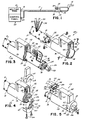
- Fig. 1 is a schematic illustration showing the arrangement of a hot melt system to which this invention is particularly applicable.
- Fig. 2 is a perspective view of the connector of the present invention in position to be slid over the end of the hose.
- Fig. 3 is a perspective view showing the connector slid over the end of the hose readied for insertion of the electrical leads in the plug block.
- Fig. 4 is a perspective view showing the connector mounted on the hose end in position to receive the end cover.
- Fig. 5 is a perspective view showing the completed mounting of the connector on the hose end and the relative location of the gun plug.
- Fig. 6 is a cross-sectional view taken along line 6-6 of Fig. 5.
- Fig. 7 is an end view taken along line 7-7 of Fig. 2.
- Fig. 8 is an end view taken along line 8-8 of Fig. 2.
- a thermally insulated electrically heated hose 10 for transporting molten thermoplastic material or so-called "hot melt” adhesive from a melter tank 12 to an applicator or dispensing gun 14.
- the melter tank or source of molten material is intended to be attached to the unit end 16 of the hose 10, and the dispensing gun 14 is attached to the gun end 18 which is remote from the unit end 16 and the melting tank 12.
- the unit end 16 of the hose is equipped with an electrical plug 20 which connects the electrical leads of the hose, as explained more full hereinafter, to the control panel 22 at the melter 12.
- the gun end 18 of the hose is equipped with a connector 24 for connecting the electrical leads contained within the hose to a plug 25 connected by electrical leads to the electrical components of the gun 14.
- the hose 10 is intended to transport molten adhesive at a pressure of several ten kp/cm2 (several hundred psi) and at a temperature on the order of 121,1°C to 176,6°C (250°F to 350°F) while maintaining the material at that temperature.
- the hose may be required to melt material contained within the hose if the material should cool and solidify as commonly does between shifts or overnight when the dispenser gun with which the hose is utilized is inoperative.
- the hose includes electrical resistance heaters contained within the hose and extending the length of the hose. These heaters are covered by insulated material so as to enable the hose to be contacted or touched by the operator of the dispensing gun without any physical harm.
- the tube is helically wound with five electrical leads four of these leads are insulated leads and the fifth lead is a braided ground wire which may be covered with an insulative material.
- Two of the leads are intended to be connected to the heater of the dispensing gun 14 to prevent the hot melt adhesive from solidifying within the gun and two leads are intended to be connected to the temperature controller of the dispensing gun.
- the ground wire serves to ground the gun. As stated, the opposite ends of these wires are connected to the control panel 22, which serves as a source of electrical power to the gun.
- a gun end 18 of the hose 10 i.e., the end remote from the melter 12 is shown.
- This end of the hose terminates in a nipple 26 (shown in Fig. 3) which is externally threaded for receiving a conventional hydraulic female swivel enabling the hose to be attached to a conventional hot melt gun.
- a hex nut 28 is threaded on the nipple and lies inboard of the swivel.
- Four leads 30, 31, 32 and 33 and the ground wire 34 pass radially from the side of the hose 10. These leads are connected at the opposite end 20 to the control panel 22 of the melter 12.
- the connector 24 includes a one-piece molded plastic cuff 36 having a through opening 38 of a size such that the cuff 36 can be slid on the end 18 of the hose 10.
- a plug block housing 40 is integrally molded with the cuff 36 as is a plug block 42 interiorly of the plug block housing 40.
- the plug block 42 includes a plurality of through openings 44 best seen in the end view shown in Fig. 7.
- a plug block cavity 46 is located at the outboard end of the connector 24.
- a groove 48 extends about the periphery of the plug block housing 40 and cuff 36 at the outboard end of the connector, interrupted by a pair of ears 39, for mounting of an end cover as will be more fully described.
- Latch members 50 extend from the outer surface of the plug block housing 40 for securing the gun plug to the connector as will also be more fully explained.
- the terminals 52 are now inserted in predetermined ones of the through openings 44 in the plug block 42 by inserting them from the outboard end of the hose in a direction generally along the long axis of the hose as shown in Fig. 3. (The length of the leads is exaggerated for purposes of clarity of description. Generally, their length is substantially that from the surface of the hose to their respective openings 44.)
- the terminals 52 preferably include integral spring elements for holding them in the plug block openings 44.
- the connector is slid toward the outboard end 18 of the hose 10. In doing so, the excess length of the leads 30-34 extending from the side of the hose is captured in the plug block cavity 46.
- An end cover 60 includes two half portions 62 and 64 which slide on the outboard end of the cuff 36 and plug block housing 40 and, when assembled thereon, correspond to the outline thereof. Mounting screws 66 secure the two halves 62, 64 together. Each end cover half 62, 64 has a cutout 67 which define a slot when the two halves are mated into which the ears 39 on the cuff fit on either side to prevent rotation of the cuff relative to the end cover halves. Each end cover further has a semicircular cutout 68, 70, respectively, which when mated form a circular opening surrounding the nipple 26. Interiorly of the cutouts 68 and 70 and on each half of the block is a Y-shaped groove 72. When the end cover 60 is assembled over the end of the hose 10, this Y-shaped groove mates with flats 74 of the hex nut 28 mounted on the nipple 26 to prevent the connector 24 from rotating relative to the hose 10.
- a gun plug 25 is insertable in the plug block housing 40 from inboard side of the connector 24.
- the gun plug includes electrical leads 79 adapted to connect with the connectors 52 fixed in the openings 44 in the plug block 42.
- three keys 80 are provided in the gun plug 25 which slide into grooves 82 in the plug block to insure that the plug block is inserted in the proper orientation to connect the proper leads.
- the gun plug includes on either side spring latches 84 which are integrally molded to the body of the plug 25 at a point intermediate their ends so that they are flexible on the plug 25.
- the forward end 86 is adapted to engage the latch members 50 on the plug block housing 40 to thereby hold the gun plug in mating relationship with the connector 42.
- To disconnect the gun plug from the connector it is merely necessary to pinch the rearward ends 88 of the latches 84 between thumb and forefinger thereby flexing the latches outwardly and releasing them from the members 50 whereupon the gun plug 25 can be removed from the housing 40.
- the connector 24 of the present invention comprises but a few easily assembleable parts.
- the cuff 36 is easily installed on the hose 10 merely by slipping the one piece over the hose end.
- the connection of the electrical leads 30-34 to the plug block 42 is substantially eased by their insertion from the outboard side of the connector 24 along the long axis of the hose 10 after which the connector 24 is slid to the outboard end of the hose 10 and the end cover 60 placed in position to hold the connector 24 on the end 18 of the hose 10 and prevent both axial and rotative movement of the connector 24 with respect to the hose.
Landscapes
- Engineering & Computer Science (AREA)
- General Engineering & Computer Science (AREA)
- Mechanical Engineering (AREA)
- Coating Apparatus (AREA)
- Details Of Connecting Devices For Male And Female Coupling (AREA)
Description
- This invention relates to application of hot melt adhesives and, more particularly, to a connector for connecting a hot melt applicator to a remote source of electrical power for operating the applicator.
- Thermoplastic adhesives or so-called "hot melt" adhesives are now widely used to secure substrates together in a great variety of applications. These hot melt materials are essentially solvent free adhesives which are applied in a molten state and form a bond upon cooling to a solid state. By reason of their quick setting characteristics, their adhesive "tack" and their gap filling properties, they are used in many industrial adhesive applications. For example, such adhesives are now commonly used in the assembly and manufacture of automobiles, furniture, aircraft subassemblies and the like. Many of these assembly operations use production line techniques wherein the adhesive applicator must be moved by an operator to and around the assembly part during application of the adhesive to the substrate. In such applications the adhesive is quite commonly applied to the substrate by an adhesive handgun to which the molten adhesive is supplied through a flexible hose. In this type of system, the molten feedstock or molten adhesive is converted from a solid state, e.g., pellets, bulk or chunks, to a molten state by a melter structure such as an electrically heated melting tank remote from the applicator. The molten feedstock is pumped from the melting tank to the gun or dispenser through a feed hose which is heated to a temperature on the order of 176,7°C (350°F) to prevent the molten feedstock from solidifying in the hose as it travels between the melting tank and the applicator. This hose is connected at its end remote from the melting tank to the applicator such that the molten adhesive is delivered to the gun. The gun has an on and off actuation so that the material may be applied as the operator determines.
- Since it is necessary for the hot melt adhesive to stay in its molten condition until applied to the substrate, the applicator or gun itself contains a heater as well as a temperature controller in the gun. The heater and temperature controller are typically electrically operated and thus the gun requires the delivery of electrical power to it.
- A thermally insulated electrically heated hose for transmitting hot melt adhesive to an applicator is disclosed in U. S. Patent No. 4,455,474, assigned to the assignee of this invention. That hose as disclosed includes two pair of electrical wires which run along the length of the hose as well as one ground wire. These electrical wires are connected at the end of the hose close to the melting tank to a source of electric power. At the opposite end or end remote from the source of adhesive material and power, the wires extend radially from the side of the hose. A connector for connecting these wires to the applicator is also disclosed comprising a cuff fitting over the end of the hose having a hole or aperture in its side through which the electrical leads pass and a plastic block which is mounted to a boss surrounding the aperture by conventional screws. The electrical leads are drawn up through the aperture and inserted in one end of a conventional electrical plug. The wires are then pushed back into the block and aperture and the plug secured in the block by means of another screw. That block then receives the a plug connection of electrical leads from the gun.
- It has been among the principal objects of this invention to provide an improved electrical connector for connecting a hot melt applicator to electrical leads passing through the side of the hose transmitting the hot melt adhesive to the gun which has an improved design, improved manufacturability and improved ease of use in mounting on the end of the hose. To this end, a presently preferred embodiment of the electrical connector includes a one piece molded plastic cuff having a through opening permitting it to be slid on the end of a hose, a plug block housing integral with the cuff including an integral internal plug block and a plug block cavity, and an end cover for covering the plug block cavity. The plug block includes a plurality of through openings for receiving and retaining the electrical leads at the end of the wires passing from the side of the hose. These leads are inserted through the plug block cavity from the outboard end of the hose and extend therein providing connections for a plug attached to the end of the wires leading to the applicator. The end cap is a two piece member which is slidable in a groove extending about the cuff and plug block housing such that the members mate when slid into position and then may be fastened together with screws. These members include internal surfaces which mate with the surfaces of a hex nut on the outboard end of the hose to thereby prevent rotation of the connector on the end of the hose during use of the applicator. As stated, a plug from the gun is inserted in the inboard end of the plug block housing where the leads therein connect with the leads in the plug block. Integrally molded latch members on the side of the plug block housing interact with spring latches on the gun plug to hold the gun plug in the housing and prevent its accidental dislodgement. These latches may be released by hand pressure to disconnect the gun from the source of electrical power.
- The connector of the present invention provides an improved one-piece integrally molded design including cuff, plug block housing and plug block. Thus, the cuff does not need screws or other fasteners to secure it to the hose end nor is it required that the housing be mechanically fastened to the cuff. Access to the plug block is through the outboard end of the cuff through the plug housing cavity. This provides for easy insertion of the electrical leads in the openings in the plug block and for disposing of excess wire length within the cavity. The end cover seals the plug block cavity when mounted to the cuff and housing thereby closing off access to the leads. The end cover includes internal surfaces which mate with the faces of a hex nut mounted on a nipple on the outboard end of the hose to prevent rotation of the connector on the hose end. All in all, the connector of the present invention is easy to install on the hose end and the electrical leads are easily installed in the plug block. The gun plug in turn need merely be inserted in the inboard end of the plug block housing to electrically connect the gun to the electrical leads. A key and slot arrangement in the gun block and plug block respectively, located off the center line of the connector, prevents the plug from being inserted other than in the predetermined manner thus preventing improper connection of the electrical leads.
- Fig. 1 is a schematic illustration showing the arrangement of a hot melt system to which this invention is particularly applicable.
- Fig. 2 is a perspective view of the connector of the present invention in position to be slid over the end of the hose.
- Fig. 3 is a perspective view showing the connector slid over the end of the hose readied for insertion of the electrical leads in the plug block.
- Fig. 4 is a perspective view showing the connector mounted on the hose end in position to receive the end cover.
- Fig. 5 is a perspective view showing the completed mounting of the connector on the hose end and the relative location of the gun plug.
- Fig. 6 is a cross-sectional view taken along line 6-6 of Fig. 5.
- Fig. 7 is an end view taken along line 7-7 of Fig. 2.
- Fig. 8 is an end view taken along line 8-8 of Fig. 2.
- Referring first to Fig. 1, there is illustrated in schematic form a thermally insulated electrically heated
hose 10 for transporting molten thermoplastic material or so-called "hot melt" adhesive from a melter tank 12 to an applicator or dispensinggun 14. The melter tank or source of molten material is intended to be attached to theunit end 16 of thehose 10, and thedispensing gun 14 is attached to thegun end 18 which is remote from theunit end 16 and the melting tank 12. Theunit end 16 of the hose is equipped with anelectrical plug 20 which connects the electrical leads of the hose, as explained more full hereinafter, to thecontrol panel 22 at the melter 12. Similarly, thegun end 18 of the hose is equipped with aconnector 24 for connecting the electrical leads contained within the hose to aplug 25 connected by electrical leads to the electrical components of thegun 14. - The details of construction of a thermally insulated electrically heated hose for transmitting hot melt adhesive to the gun are set forth in the aforementioned U. S. Patent No. 4,455,474 and that disclosure is incorporated herein by reference. In general, in accordance with the teachings of that patent, the
hose 10 is intended to transport molten adhesive at a pressure of several ten kp/cm² (several hundred psi) and at a temperature on the order of 121,1°C to 176,6°C (250°F to 350°F) while maintaining the material at that temperature. Additionally, the hose may be required to melt material contained within the hose if the material should cool and solidify as commonly does between shifts or overnight when the dispenser gun with which the hose is utilized is inoperative. Thus, the hose includes electrical resistance heaters contained within the hose and extending the length of the hose. These heaters are covered by insulated material so as to enable the hose to be contacted or touched by the operator of the dispensing gun without any physical harm. - The tube is helically wound with five electrical leads four of these leads are insulated leads and the fifth lead is a braided ground wire which may be covered with an insulative material. Two of the leads are intended to be connected to the heater of the dispensing
gun 14 to prevent the hot melt adhesive from solidifying within the gun and two leads are intended to be connected to the temperature controller of the dispensing gun. The ground wire serves to ground the gun. As stated, the opposite ends of these wires are connected to thecontrol panel 22, which serves as a source of electrical power to the gun. - Referring now to Fig. 2, the
gun end 18 of thehose 10, i.e., the end remote from the melter 12 is shown. This end of the hose terminates in a nipple 26 (shown in Fig. 3) which is externally threaded for receiving a conventional hydraulic female swivel enabling the hose to be attached to a conventional hot melt gun. Ahex nut 28 is threaded on the nipple and lies inboard of the swivel. Four leads 30, 31, 32 and 33 and theground wire 34 pass radially from the side of thehose 10. These leads are connected at theopposite end 20 to thecontrol panel 22 of the melter 12. - The
connector 24 includes a one-piece moldedplastic cuff 36 having a throughopening 38 of a size such that thecuff 36 can be slid on theend 18 of thehose 10. Aplug block housing 40 is integrally molded with thecuff 36 as is aplug block 42 interiorly of theplug block housing 40. Theplug block 42 includes a plurality of throughopenings 44 best seen in the end view shown in Fig. 7. Aplug block cavity 46 is located at the outboard end of theconnector 24. Agroove 48 extends about the periphery of theplug block housing 40 andcuff 36 at the outboard end of the connector, interrupted by a pair ofears 39, for mounting of an end cover as will be more fully described.Latch members 50 extend from the outer surface of theplug block housing 40 for securing the gun plug to the connector as will also be more fully explained. - The
connector 24 is slid over theend 18 of thehose 10. The leads 30-34 have sufficient resiliency that they are first bent down as thehose 10 passes through the throughopening 38. As theconnector 24 continues to be slid on thehose 10, the leads pass out from the through opening and spring back generally to an upright position. The exposed wire of the electrical leads 30-34 are all connected to the ends of conventional crimped terminals 52 (Fig. 3). These terminals may be either of the male or female type. However, it is preferred that they be female so when mounted in theplug block 42 there are not "hot" pins sticking out. Aconventional metal band 54 is clamped over the end of thehose 10 so as to clamp the hose insulative materials in compression within the band. Theterminals 52 are now inserted in predetermined ones of the throughopenings 44 in theplug block 42 by inserting them from the outboard end of the hose in a direction generally along the long axis of the hose as shown in Fig. 3. (The length of the leads is exaggerated for purposes of clarity of description. Generally, their length is substantially that from the surface of the hose to theirrespective openings 44.) Theterminals 52 preferably include integral spring elements for holding them in theplug block openings 44. - Referring now to Fig. 4, the connector is slid toward the
outboard end 18 of thehose 10. In doing so, the excess length of the leads 30-34 extending from the side of the hose is captured in theplug block cavity 46. - An
end cover 60 includes twohalf portions cuff 36 and plugblock housing 40 and, when assembled thereon, correspond to the outline thereof. Mountingscrews 66 secure the twohalves half cutout 67 which define a slot when the two halves are mated into which theears 39 on the cuff fit on either side to prevent rotation of the cuff relative to the end cover halves. Each end cover further has asemicircular cutout nipple 26. Interiorly of thecutouts groove 72. When theend cover 60 is assembled over the end of thehose 10, this Y-shaped groove mates withflats 74 of thehex nut 28 mounted on thenipple 26 to prevent theconnector 24 from rotating relative to thehose 10. - The completed assembly of the
connector 24 on thehose end 18 is shown in Figs. 5 and 6. Agun plug 25 is insertable in theplug block housing 40 from inboard side of theconnector 24. The gun plug includeselectrical leads 79 adapted to connect with theconnectors 52 fixed in theopenings 44 in theplug block 42. As shown in Figs. 5 and 8, threekeys 80 are provided in thegun plug 25 which slide intogrooves 82 in the plug block to insure that the plug block is inserted in the proper orientation to connect the proper leads. - The gun plug includes on either side spring latches 84 which are integrally molded to the body of the
plug 25 at a point intermediate their ends so that they are flexible on theplug 25. Theforward end 86 is adapted to engage thelatch members 50 on theplug block housing 40 to thereby hold the gun plug in mating relationship with theconnector 42. To disconnect the gun plug from the connector, it is merely necessary to pinch the rearward ends 88 of thelatches 84 between thumb and forefinger thereby flexing the latches outwardly and releasing them from themembers 50 whereupon thegun plug 25 can be removed from thehousing 40. - As may be appreciated from the foregoing description, the
connector 24 of the present invention comprises but a few easily assembleable parts. Thecuff 36 is easily installed on thehose 10 merely by slipping the one piece over the hose end. The connection of the electrical leads 30-34 to theplug block 42 is substantially eased by their insertion from the outboard side of theconnector 24 along the long axis of thehose 10 after which theconnector 24 is slid to the outboard end of thehose 10 and theend cover 60 placed in position to hold theconnector 24 on theend 18 of thehose 10 and prevent both axial and rotative movement of theconnector 24 with respect to the hose.
Claims (4)
- An electrical connector adapted to be mounted on the end of a hose (10) delivering molten material from a source of hot melt to a hot melt applicator for receiving and retaining the electrical lead ends (52) of wires (30-34, 79) carried by said hose (10), comprising:
a one-piece molded plastic cuff (36) having a through opening (38) of a size such that said cuff (36) can be slid on the end (18) of a hose (10),
a plug block housing (40) integral with said cuff (36) including an integral plug block (42) having a plurality of through openings (44) for receiving and retaining said electrical lead ends (52), said lead ends (52) being adapted to be inserted therein from the outboard end (18) of said hose (10) in a direction generally along the long axis of the hose (10), and a plug block cavity (46) through which said wires (30-34) terminating in said lead ends (52) can pass, said plug block cavity (46) being adapted to be disposed at the outboard end (18) of the hose (10) when said connector (24) is mounted on said end (18) of said hose (10), and
an end cover (60) covering said plug block cavity (46), and including means (67) to prevent rotation of said connector (24) on said hose end (18). - The electrical connector of claim 1 wherein said hose end (18) includes a nipple (26) with a hex nut (28) mounted thereon, wherein said cuff (36) and integral housing (40) including a peripheral groove (48) and a pair of diametrically opposed ears (39) extending across said groove (48), and wherein said end cover (60) comprises two portions (62,64) adapted to mate and be secured together, each said end cover portion (62,64) including a peripheral flange adapted to slide in said groove (48) and be retained therein, each said peripheral flange having a pair of opposed cutouts (67) such that when said portions (62,64) are mated said cutouts (67) define a slot capturing said ears (39) to prevent rotation of said cuff (36) and integral housing (40) with respect to said end cover (60), each said end cover portion (62,64) further including a Y-shaped slot (72) having a pair of flats (74) adapted to engage the flats on said hex nut (28) to prevent rotation of said end cover (60) and in turn said cuff (36) and integral housing (40) with respect to said hose (10).
- The electrical connector of claim 1 or 2 wherein said housing (40) further comprises a pair of external latch members (50) adapted to engage spring latch elements (84) on a plug (25) adapted to be received in said plug block housing (40) and wherein said plug block includes a key and slot arrangement (80,82) for insuring that said end plug is received in said plug block in only a single orientation.
- The electrical connector as claimed in any one of claims 1 to 3 further including a hose (10) secured to the connector (24) and electrical wires (30 - 34) extending along said hose (10) and connected to said electrical lead ends (52).
Applications Claiming Priority (2)
| Application Number | Priority Date | Filing Date | Title |
|---|---|---|---|
| US691074 | 1985-01-14 | ||
| US06/691,074 US4616894A (en) | 1985-01-14 | 1985-01-14 | Electrical connector for hot melt hose unit and gun |
Publications (3)
| Publication Number | Publication Date |
|---|---|
| EP0187943A2 EP0187943A2 (en) | 1986-07-23 |
| EP0187943A3 EP0187943A3 (en) | 1989-06-07 |
| EP0187943B1 true EP0187943B1 (en) | 1992-04-01 |
Family
ID=24775050
Family Applications (1)
| Application Number | Title | Priority Date | Filing Date |
|---|---|---|---|
| EP85115437A Expired - Lifetime EP0187943B1 (en) | 1985-01-14 | 1985-12-05 | Electrical connector for hot melt hose unit and gun |
Country Status (5)
| Country | Link |
|---|---|
| US (1) | US4616894A (en) |
| EP (1) | EP0187943B1 (en) |
| JP (1) | JPH0795459B2 (en) |
| CA (1) | CA1239676A (en) |
| DE (1) | DE3585785D1 (en) |
Families Citing this family (30)
| Publication number | Priority date | Publication date | Assignee | Title |
|---|---|---|---|---|
| FR2603086B1 (en) * | 1986-08-19 | 1989-01-06 | Fraco Sa | PIPE FOR VEHICLE AND HEATING A PRODUCT, WITH WHICH HEATING MEANS ARE INTEGRATED INTO THE PIPE |
| DE4213784C2 (en) * | 1992-04-27 | 2001-07-05 | U E S Klebetechnik Gmbh | Application head for applications in hot and cold glue technology |
| WO1996011356A1 (en) * | 1994-10-05 | 1996-04-18 | Exxon Chemical Patents Inc. | Hot melt flexible hose with replaceable core |
| US5573414A (en) | 1995-03-16 | 1996-11-12 | Mechanical Dynamics & Analysis, Inc. | Two piece electrical and fluidic connector and installation method therefore |
| US5959828A (en) * | 1996-07-16 | 1999-09-28 | Hydraflow | Coupling with insulated flanges |
| US5786976A (en) * | 1996-07-16 | 1998-07-28 | Hydraflow | Coupling with hard metallic ductile conductive coating |
| US7216777B2 (en) * | 2002-10-31 | 2007-05-15 | Nordson Corporation | Liquid dispensing system using color-coded visual indicia |
| US20050008353A1 (en) * | 2003-07-08 | 2005-01-13 | Nordson Corporation | Heated hose for carrying molten thermoplastic material |
| US7332692B2 (en) * | 2005-05-06 | 2008-02-19 | Illinois Tool Works Inc. | Redundant control circuit for hot melt adhesive assembly heater circuits and temperature sensors |
| US7351937B2 (en) * | 2005-05-06 | 2008-04-01 | Illinois Tool Works Inc. | Control circuits for hot melt adhesive heater circuits and applicator heads |
| US7773867B2 (en) * | 2005-05-06 | 2010-08-10 | Illinois Tool Works Inc. | Hot melt adhesive hose assembly having redundant components |
| US7605351B2 (en) * | 2005-05-06 | 2009-10-20 | Illinois Tool Works Inc. | Redundant control circuit for hot melt adhesive hose assembly heater circuits and temperature sensors |
| US7732735B2 (en) * | 2005-05-06 | 2010-06-08 | Illinois Tool Works Inc. | Hot melt adhesive hose assembly having redundant components |
| US8291939B2 (en) * | 2005-07-29 | 2012-10-23 | Sykes Hollow Innovations, Ltd. | Grounding system for a heated hose |
| DE102005057780A1 (en) | 2005-12-02 | 2007-06-06 | Dbk David + Baader Gmbh | Fluid coupling assembly with electrical connector assembly |
| US7732736B2 (en) * | 2007-03-30 | 2010-06-08 | Illinois Tool Works Inc. | Hot melt adhesive hose assembly with thermal fuse link |
| CN103644421B (en) * | 2007-04-26 | 2016-11-02 | 福士汽车配套部件责任有限公司 | Catheter extension for media lines |
| US20080298788A1 (en) * | 2007-06-04 | 2008-12-04 | Teleflex Fluid Systems, Inc. | Heated hose apparatus and method |
| DE102008008267B4 (en) * | 2008-02-08 | 2010-07-01 | Volkswagen Ag | Protective cap, mounting arrangement and method for the assembly of pipes in the shell of a motor vehicle |
| US9651185B2 (en) | 2008-03-19 | 2017-05-16 | Voss Automotive Gmbh | Line connector for media lines |
| DE102008022663B4 (en) | 2008-05-07 | 2012-10-31 | Schauenburg Hose Technology Gmbh | Stretch hose |
| US9505164B2 (en) | 2009-12-30 | 2016-11-29 | Schauenburg Technology Se | Tapered helically reinforced hose and its manufacture |
| US9964238B2 (en) | 2009-01-15 | 2018-05-08 | Globalmed, Inc. | Stretch hose and hose production method |
| US8863782B2 (en) | 2009-05-06 | 2014-10-21 | Sykes Hollow Innovations, Ltd. | Grounding system for a heated hose |
| GB0918042D0 (en) | 2009-10-15 | 2009-12-02 | Delphi Tech Inc | Connector assembly and method of manufacturing same |
| US8550610B2 (en) * | 2009-12-13 | 2013-10-08 | Xerox Corporation | Electroconductive tubing for heating and transporting liquefied solid ink |
| CA2875043C (en) * | 2013-12-12 | 2019-08-20 | Heat-Line Corporation | Heating cables |
| CA2973992A1 (en) | 2016-07-21 | 2018-01-21 | Heat-Line Corporation | End seal for heating cable |
| US10792454B2 (en) | 2017-01-30 | 2020-10-06 | Globalmed, Inc. | Heated respiratory hose assembly |
| CN114843371B (en) * | 2022-04-28 | 2024-09-06 | 安徽华晟新能源科技有限公司 | Preparation method of solar cell module |
Family Cites Families (18)
| Publication number | Priority date | Publication date | Assignee | Title |
|---|---|---|---|---|
| US1098620A (en) * | 1913-02-01 | 1914-06-02 | Henry Gillar | Hose connection. |
| US1230854A (en) * | 1916-08-31 | 1917-06-26 | Erich F J Breuer | Hose-coupling. |
| US1733072A (en) * | 1927-09-24 | 1929-10-22 | Keystone Specialty Company | Universal-joint attachment |
| US1931703A (en) * | 1931-04-18 | 1933-10-24 | Blaw Knox Co | Thread protector |
| US2208706A (en) * | 1939-01-04 | 1940-07-23 | Raphael M Spencer | Hose clamp |
| US3127227A (en) * | 1961-02-27 | 1964-03-31 | Vacuum cleaner connector | |
| US3419291A (en) * | 1967-01-30 | 1968-12-31 | Corning Glass Works | Pipe coupling |
| US3523269A (en) * | 1968-03-08 | 1970-08-04 | Essex International Inc | Panel locking terminal connector block |
| US3475718A (en) * | 1968-09-06 | 1969-10-28 | Essex International Inc | Connector block |
| US3553629A (en) * | 1968-09-09 | 1971-01-05 | Cons Foods Corp | Electric hose with end fittings for a vacuum cleaner |
| GB1362265A (en) * | 1971-03-12 | 1974-08-07 | Cannon Electric Great Britain | Electrical connectors |
| US4114929A (en) * | 1975-08-13 | 1978-09-19 | Robert Bosch Gmbh | Plastic pipe or hose connection for fuel conduits |
| US4039210A (en) * | 1976-06-28 | 1977-08-02 | Phillips Petroleum Company | Coupling adapter for plastic pipe |
| US4236736A (en) * | 1978-05-01 | 1980-12-02 | Turnbuckle Products Corporation | Hose coupling |
| US4277640A (en) * | 1979-04-26 | 1981-07-07 | Automation Industries, Inc. | Electric current-carrying hose assembly having end fittings enclosing an electrical switch and/or a circuit-breaking device |
| US4310211A (en) * | 1979-12-26 | 1982-01-12 | Amp Incorporated | High current contact system for solar modules |
| FR2499030A2 (en) * | 1981-01-30 | 1982-08-06 | Flimon Jacques | PROTECTIVE DEVICE FOR DRILLING TUBES, ESPECIALLY OIL |
| US4455474A (en) * | 1981-11-27 | 1984-06-19 | Nordson Corporation | Thermally insulated electrically heated hose for transmitting hot liquids |
-
1985
- 1985-01-14 US US06/691,074 patent/US4616894A/en not_active Expired - Lifetime
- 1985-12-04 CA CA000496858A patent/CA1239676A/en not_active Expired
- 1985-12-05 DE DE8585115437T patent/DE3585785D1/en not_active Expired - Lifetime
- 1985-12-05 EP EP85115437A patent/EP0187943B1/en not_active Expired - Lifetime
-
1986
- 1986-01-14 JP JP61004446A patent/JPH0795459B2/en not_active Expired - Fee Related
Also Published As
| Publication number | Publication date |
|---|---|
| EP0187943A3 (en) | 1989-06-07 |
| EP0187943A2 (en) | 1986-07-23 |
| JPH0795459B2 (en) | 1995-10-11 |
| JPS61165971A (en) | 1986-07-26 |
| DE3585785D1 (en) | 1992-05-07 |
| US4616894A (en) | 1986-10-14 |
| CA1239676A (en) | 1988-07-26 |
Similar Documents
| Publication | Publication Date | Title |
|---|---|---|
| EP0187943B1 (en) | Electrical connector for hot melt hose unit and gun | |
| US4455474A (en) | Thermally insulated electrically heated hose for transmitting hot liquids | |
| US4553023A (en) | Thermally insulated electrically heated hose for transmitting hot liquids | |
| US6257923B1 (en) | Dual media connector for a vehicle | |
| CN101513117B (en) | Modular heater systems | |
| JPH10222U (en) | Fuel distribution device | |
| CN101795853B (en) | Sealing fluid container assembly, and kit for repairing and inflating inflatable articles and equipped with such container | |
| US4359255A (en) | Coupling ring having detent means | |
| US20210078419A1 (en) | Temperature sensor for terminal of charging inlet assembly | |
| US4983344A (en) | Method for injection molding a sealed connector assembly | |
| EP0052538A2 (en) | Electrical connector coupling member | |
| JP2002500721A (en) | Fuel transfer module flange and fuel transfer module | |
| US4622455A (en) | Connection assembly for electric cartridge heater | |
| US4644134A (en) | Electrically heated hose having corrugated plastic cover | |
| US7005591B1 (en) | Thermostatic cord | |
| US20040182370A1 (en) | Electrically heated throttle body | |
| EP0360483B1 (en) | Equipment for delivering a fluid | |
| US5681188A (en) | Electrical connector | |
| US20240213720A1 (en) | Heated hose electrical connectors | |
| CN220996508U (en) | Sensor housing assembly and electric power steering system | |
| US4518016A (en) | Hot melt adhesive hose cuff | |
| CN213018288U (en) | Plastic hose quick coupling | |
| CN220368260U (en) | Circuit distributor | |
| JPWO2020219355A5 (en) | ||
| JPH1187027A (en) | Heater unit |
Legal Events
| Date | Code | Title | Description |
|---|---|---|---|
| PUAI | Public reference made under article 153(3) epc to a published international application that has entered the european phase |
Free format text: ORIGINAL CODE: 0009012 |
|
| AK | Designated contracting states |
Kind code of ref document: A2 Designated state(s): BE CH DE FR GB LI NL |
|
| PUAL | Search report despatched |
Free format text: ORIGINAL CODE: 0009013 |
|
| AK | Designated contracting states |
Kind code of ref document: A3 Designated state(s): BE CH DE FR GB LI NL |
|
| 17P | Request for examination filed |
Effective date: 19890608 |
|
| 17Q | First examination report despatched |
Effective date: 19801108 |
|
| GRAA | (expected) grant |
Free format text: ORIGINAL CODE: 0009210 |
|
| AK | Designated contracting states |
Kind code of ref document: B1 Designated state(s): BE CH DE FR GB LI NL |
|
| ET | Fr: translation filed | ||
| REF | Corresponds to: |
Ref document number: 3585785 Country of ref document: DE Date of ref document: 19920507 |
|
| PGFP | Annual fee paid to national office [announced via postgrant information from national office to epo] |
Ref country code: FR Payment date: 19921111 Year of fee payment: 8 |
|
| PGFP | Annual fee paid to national office [announced via postgrant information from national office to epo] |
Ref country code: CH Payment date: 19921116 Year of fee payment: 8 |
|
| PGFP | Annual fee paid to national office [announced via postgrant information from national office to epo] |
Ref country code: GB Payment date: 19921119 Year of fee payment: 8 |
|
| PGFP | Annual fee paid to national office [announced via postgrant information from national office to epo] |
Ref country code: DE Payment date: 19921125 Year of fee payment: 8 |
|
| PGFP | Annual fee paid to national office [announced via postgrant information from national office to epo] |
Ref country code: BE Payment date: 19921126 Year of fee payment: 8 |
|
| PGFP | Annual fee paid to national office [announced via postgrant information from national office to epo] |
Ref country code: NL Payment date: 19921231 Year of fee payment: 8 |
|
| PLBE | No opposition filed within time limit |
Free format text: ORIGINAL CODE: 0009261 |
|
| STAA | Information on the status of an ep patent application or granted ep patent |
Free format text: STATUS: NO OPPOSITION FILED WITHIN TIME LIMIT |
|
| 26N | No opposition filed | ||
| PG25 | Lapsed in a contracting state [announced via postgrant information from national office to epo] |
Ref country code: GB Effective date: 19931205 |
|
| PG25 | Lapsed in a contracting state [announced via postgrant information from national office to epo] |
Ref country code: LI Effective date: 19931231 Ref country code: CH Effective date: 19931231 Ref country code: BE Effective date: 19931231 |
|
| BERE | Be: lapsed |
Owner name: NORDSON CORP. Effective date: 19931231 |
|
| PG25 | Lapsed in a contracting state [announced via postgrant information from national office to epo] |
Ref country code: NL Effective date: 19940701 |
|
| GBPC | Gb: european patent ceased through non-payment of renewal fee |
Effective date: 19931205 |
|
| NLV4 | Nl: lapsed or anulled due to non-payment of the annual fee | ||
| PG25 | Lapsed in a contracting state [announced via postgrant information from national office to epo] |
Ref country code: FR Effective date: 19940831 |
|
| REG | Reference to a national code |
Ref country code: CH Ref legal event code: PL |
|
| PG25 | Lapsed in a contracting state [announced via postgrant information from national office to epo] |
Ref country code: DE Effective date: 19940901 |
|
| REG | Reference to a national code |
Ref country code: FR Ref legal event code: ST |