EP4102260A1 - Method and apparatus for removing tube wave interference from optical fiber acoustic wave sensing seismic data - Google Patents
Method and apparatus for removing tube wave interference from optical fiber acoustic wave sensing seismic data Download PDFInfo
- Publication number
- EP4102260A1 EP4102260A1 EP21749991.2A EP21749991A EP4102260A1 EP 4102260 A1 EP4102260 A1 EP 4102260A1 EP 21749991 A EP21749991 A EP 21749991A EP 4102260 A1 EP4102260 A1 EP 4102260A1
- Authority
- EP
- European Patent Office
- Prior art keywords
- seismic
- tube wave
- time point
- sampling time
- seismic trace
- Prior art date
- Legal status (The legal status is an assumption and is not a legal conclusion. Google has not performed a legal analysis and makes no representation as to the accuracy of the status listed.)
- Granted
Links
Images


Classifications
-
- G—PHYSICS
- G01—MEASURING; TESTING
- G01V—GEOPHYSICS; GRAVITATIONAL MEASUREMENTS; DETECTING MASSES OR OBJECTS; TAGS
- G01V1/00—Seismology; Seismic or acoustic prospecting or detecting
- G01V1/40—Seismology; Seismic or acoustic prospecting or detecting specially adapted for well-logging
- G01V1/44—Seismology; Seismic or acoustic prospecting or detecting specially adapted for well-logging using generators and receivers in the same well
- G01V1/48—Processing data
-
- G—PHYSICS
- G01—MEASURING; TESTING
- G01V—GEOPHYSICS; GRAVITATIONAL MEASUREMENTS; DETECTING MASSES OR OBJECTS; TAGS
- G01V1/00—Seismology; Seismic or acoustic prospecting or detecting
- G01V1/22—Transmitting seismic signals to recording or processing apparatus
- G01V1/226—Optoseismic systems
-
- G—PHYSICS
- G01—MEASURING; TESTING
- G01V—GEOPHYSICS; GRAVITATIONAL MEASUREMENTS; DETECTING MASSES OR OBJECTS; TAGS
- G01V1/00—Seismology; Seismic or acoustic prospecting or detecting
- G01V1/16—Receiving elements for seismic signals; Arrangements or adaptations of receiving elements
- G01V1/18—Receiving elements, e.g. seismometer, geophone or torque detectors, for localised single point measurements
-
- G—PHYSICS
- G01—MEASURING; TESTING
- G01V—GEOPHYSICS; GRAVITATIONAL MEASUREMENTS; DETECTING MASSES OR OBJECTS; TAGS
- G01V1/00—Seismology; Seismic or acoustic prospecting or detecting
- G01V1/28—Processing seismic data, e.g. for interpretation or for event detection
- G01V1/30—Analysis
- G01V1/307—Analysis for determining seismic attributes, e.g. amplitude, instantaneous phase or frequency, reflection strength or polarity
-
- G—PHYSICS
- G01—MEASURING; TESTING
- G01V—GEOPHYSICS; GRAVITATIONAL MEASUREMENTS; DETECTING MASSES OR OBJECTS; TAGS
- G01V1/00—Seismology; Seismic or acoustic prospecting or detecting
- G01V1/28—Processing seismic data, e.g. for interpretation or for event detection
- G01V1/36—Effecting static or dynamic corrections on records, e.g. correcting spread; Correlating seismic signals; Eliminating effects of unwanted energy
- G01V1/364—Seismic filtering
-
- G—PHYSICS
- G01—MEASURING; TESTING
- G01V—GEOPHYSICS; GRAVITATIONAL MEASUREMENTS; DETECTING MASSES OR OBJECTS; TAGS
- G01V1/00—Seismology; Seismic or acoustic prospecting or detecting
- G01V1/40—Seismology; Seismic or acoustic prospecting or detecting specially adapted for well-logging
- G01V1/44—Seismology; Seismic or acoustic prospecting or detecting specially adapted for well-logging using generators and receivers in the same well
- G01V1/48—Processing data
- G01V1/50—Analysing data
-
- G—PHYSICS
- G01—MEASURING; TESTING
- G01V—GEOPHYSICS; GRAVITATIONAL MEASUREMENTS; DETECTING MASSES OR OBJECTS; TAGS
- G01V2210/00—Details of seismic processing or analysis
- G01V2210/30—Noise handling
- G01V2210/32—Noise reduction
- G01V2210/324—Filtering
-
- G—PHYSICS
- G01—MEASURING; TESTING
- G01V—GEOPHYSICS; GRAVITATIONAL MEASUREMENTS; DETECTING MASSES OR OBJECTS; TAGS
- G01V2210/00—Details of seismic processing or analysis
- G01V2210/60—Analysis
- G01V2210/63—Seismic attributes, e.g. amplitude, polarity, instant phase
Definitions
- the present disclosure relates to the field of geophysical explorations, and particularly to a method and an apparatus for removing tube wave interference from optical fiber acoustic wave sensing seismic data.
- the optical fiber acoustic wave sensing technology is increasingly widely applied in borehole seismic explorations.
- the optical fiber acoustic wave sensing technology has the characteristics such as high-density sampling and high-temperature and high-pressure resistance.
- the optical fiber acoustic wave sensing technology mainly utilizes Rayleigh backscattering generated by laser light propagating in optical fibers. When the medium around the optical fibers vibrates, the Rayleigh scattering will change correspondingly. Through a continuous observation and demodulation of such optical signal, seismic wave information of a stratum can be obtained.
- Optical fiber acoustic wave sensing is suitable for observing seismic waves in a well.
- tube wave interference is generated abnormally because of an incomplete coupling between the optical fibers and the borehole wall of the well, and a change in a distance between the optical fibers and the borehole wall causes tube wave energy to vary greatly, which seriously affects the receiving effect of the seismic waves. It is difficult to effectively remove the tube wave interference in the application of the optical fiber acoustic wave sensing technology in the seismic exploration.
- the prior art mainly adopts two methods to remove tube wave interference from optical fiber acoustic wave sensing seismic data.
- One method is a median filtering method including: picking up a relatively accurate first arrival of a tube wave, and performing median filtering based on the first arrival of the tube wave.
- this method changes an energy relationship and phase of original seismic wavefield data while filtering out the tube wave, and there are still some strong tube waves in seismic wave records after the filtering.
- the other method is a frequency-wavenumber domain filtering method including: transforming original seismic wavefield data to obtain a frequency-wavenumber spectrum thereof, selecting an apparent velocity range of the tube wave, and clearing the frequency-wavenumber spectrum within the apparent velocity range.
- this method cannot filter out the tube wave corresponding to a spatial alias frequency, so it is difficult to effectively remove the tube wave interference.
- the conventional methods for removing tube wave interference from optical fiber acoustic wave sensing seismic data have the technical problems that the tube wave interference cannot be completely removed and valid signals may be easily filtered out.
- the embodiments of the present disclosure provide a method for removing tube wave interference from optical fiber acoustic wave sensing seismic data to solve the technical problem that the conventional methods for removing tube wave interference from optical fiber acoustic wave sensing seismic data cannot completely remove the tube wave interference and may easily filter out valid signals.
- the method includes: acquiring seismic wavefield data which contains atube wave interference and is collected by an optical fiber acoustic wave sensing instrument, in which the seismic wavefield data comprises amplitude values at each sampling time point of seismic traces excited by a single shot; downwardly cutting waveform data with a preset time window length on each seismic trace along travel time of the tube wave, and calculating a root-mean-square amplitude of the waveform data cut on the seismic trace as an amplitude normalization factor of the seismic trace; performing normalization processing on the amplitude value of each seismic trace at each sampling time point based on the amplitude normalization factor of each seismic trace, to obtain a normalized amplitude value of the seismic trace at each sampling time point; performing de-tail mean filtering processing on the normalized amplitude value of each seismic trace at each sampling time point along the travel time of the tube wave, to obtain a predicted amplitude value of the tube wave at the sampling time point; and performing tube wave interference removal processing on each seismic trace at each sampling time point based on the predicted
- the embodiments of the present disclosure provide an apparatus for removing tube wave interference from optical fiber acoustic wave sensing seismic data to solve the technical problem that the conventional methods for removing tube wave interference from optical fiber acoustic wave sensing seismic data cannot completely remove the tube wave interference and may easily filter out valid signals.
- the apparatus includes: a seismic wavefield data acquisition unit configured to acquire seismic wavefield data which contains a tube wave interference and is collected by an optical fiber acoustic wave sensing instrument, in which the seismic wavefield data comprises amplitude values at each sampling time point of seismic traces excited by a single shot; a normalization factor determination unit configured to downwardly cut waveform data with a preset time window length on each seismic trace along travel time of a tube wave, and calculate a root-mean-square amplitude of the waveform data cut on the seismic trace as an amplitude normalization factor of the seismic trace; a normalization processing unit configured to perform normalization processing on the amplitude value of each seismic trace at each sampling time point based on the amplitude normalization factor of the seismic trace, to obtain a normalized amplitude value of the seismic trace at each sampling time point; a tube wave amplitude prediction unit configured to perform de-tail mean filtering processing on the normalized amplitude value of each seismic trace at each sampling time point along the travel time of the tube wave, to obtain a
- the embodiments of the present disclosure provide a computer device to solve the technical problem that the conventional methods for removing tube wave interference from optical fiber acoustic wave sensing seismic data cannot completely remove the tube wave interference and may easily filter out valid signals.
- the computer device includes: a memory, a processor and a computer program stored in the memory and executable on the processor, in which the processor is configured to execute the computer program to implement the aforementioned method for removing tube wave interference from optical fiber acoustic wave sensing seismic data.
- the embodiments of the present disclosure provide a computer-readable storage medium to solve the technical problem that the conventional methods for removing tube wave interference from optical fiber acoustic wave sensing seismic data cannot completely remove the tube wave interference and may easily filter out valid signals.
- the computer-readable storage medium stores a computer program for implementing the aforementioned method for removing tube wave interference from optical fiber acoustic wave sensing seismic data.
- the embodiments of the present disclosure acquire seismic wavefield data which contains a tube wave interference and is collected by an optical fiber acoustic wave sensing instrument; downwardly cut waveform data with a preset time window length on each seismic trace along travel time of the tube wave, and calculate a root-mean-square amplitude of the waveform data cut on the seismic trace as an amplitude normalization factor of each seismic trace; perform normalization processing on the amplitude value of each seismic trace at each sampling time point based on the amplitude normalization factor of the seismic trace; perform de-tail mean filtering processing on the normalized result of the amplitude value of each seismic trace at each sampling time point along the travel time of the tube wave, to obtain a predicted amplitude value of the tube wave at each sampling time point; and perform
- the present disclosure can effectively suppress the tube wave interference in the optical fiber acoustic wave sensing seismic data, improve the signal-to-noise ratio of the seismic wavefield data collected by the optical fiber acoustic wave sensing instrument, highlight the seismic signals propagating along the stratum, and improve the application effect of the optical fiber sensing technology in collecting the seismic data during the seismic exploration.
- words such as 'include', 'comprise', 'have' and 'contain' are all open terms, which mean including but not limited to.
- the description of the reference terms such as 'one embodiment', 'one specific embodiment', 'some embodiments' and 'for example' means that the specific features, structures or characteristics described in connection with the embodiment(s) or example(s) are included in at least one embodiment or example of the present disclosure.
- the schematic expressions of the above terms do not necessarily refer to a same embodiment or example.
- the described specific features, structures or characteristics may be combined in any one or more embodiments or examples in a suitable manner.
- the sequence of steps involved in each embodiment is used to schematically illustrate the implementation of the present disclosure, and the sequence of steps is not limited, but can be appropriately adjusted as needed.
- FIG. 1 is a flowchart of a method for removing tube wave interference from optical fiber acoustic wave sensing seismic data according to an embodiment of the present disclosure. As illustrated in FIG. 1 , the method includes:
- S101 acquiring seismic wavefield data which contains a tube wave and is collected by an optical fiber acoustic wave sensing instrument, wherein the seismic wavefield data comprises amplitude values at each sampling time point of seismic traces excited by a single shot.
- the optical fiber acoustic wave sensing is suitable for observing seismic waves in a well, and when being suspended in the well, optical fibers are more likely to receive tube wave interference because of an incomplete coupling between the optical fibers and the borehole wall of the well.
- the tube wave interference has a relatively stable wave velocity, and the amplitude value of the tube wave is inversely proportional to the coupling degree of the optical fibers (i.e., a degree of coupling between the optical fibers and the borehole wall), that is, the amplitude value of the tube wave increases as the distance between the optical fibers and the borehole wall increases (i.e., the coupling degree of the optical fibers decreases), and vice versa.
- an excitation source for exciting the seismic wavefield data in the embodiment of the present disclosure may be explosives or artificial vibroseis.
- single-shot or multi-shot seismic data is obtained by excitation of the explosives or vibroseis
- an optical fiber acoustic wave sensor of an optical fiber acoustic wave collection instrument is suspended in a borehole by optical fibers, and seismic wavefield data including tube wave interference is acquired by the optical fiber acoustic wave sensing instrument.
- the seismic wavefield data collected by the optical fiber acoustic wave sensing instrument in S101 at least includes amplitude values at each sampling time point of seismic traces excited by a single shot.
- the tube wave interference is removed from the multi-shot seismic wavefield data collected by the optical fiber acoustic wave sensing instrument, it is only necessary to repeatedly perform S102 to S105.
- S102 downwardly cutting waveform data with a preset time window length on each seismic trace along travel time of a tube wave, and calculating a root-mean-square amplitude of the waveform data cut on the seismic trace as an amplitude normalization factor of the seismic trace.
- the tube wave interference contained in the seismic data collected by the optical fibers has a relatively stable wave velocity, it appears as an oblique line in the single shot record of the seismic data.
- waveform data with a preset time window length is downwardly cut on each seismic trace along the oblique line, and a root-mean-square amplitude of the waveform data cut on the seismic trace is calculated as an amplitude normalization factor of the seismic trace.
- a root-mean-square amplitude analysis is carried out along a time window of the tube wave, and a root-mean-square amplitude of waveform data with a preset time window length cut on each seismic trace is calculated.
- the root-mean-square amplitude can reflect tube wave energy and can be used as a normalized correction factor for the amplitude of each seismic trace, so as to remove the tube wave interference more effectively.
- the preset time window length adopted in the embodiment of the present disclosure may be 2 to10 times of a dominant period of the tube wave.
- S103 performing normalization processing on the amplitude value of each seismic trace at each sampling time point based on the amplitude normalization factor of the seismic trace, to obtain a normalized amplitude value of the seismic trace at the sampling time point.
- the normalization processing when the normalization processing is performed on the amplitudes of each seismic trace in S103, it may, but not limited to, divide the amplitude value of each seismic trace at each sampling time point by the amplitude normalization factor of the seismic trace, to obtain the normalized amplitude value of the seismic trace at each sampling time point.
- S104 performing de-tail mean filtering processing on the normalized amplitude value of each seismic trace at each sampling time point along the travel time of the tube wave, to obtain a predicted amplitude value of the tube wave at the sampling time point.
- S104 may be implemented by sorting the normalized amplitude values of the seismic traces at each sampling time point along a direction of the travel time of the tube wave, removing the first n normalized amplitude values and the last n normalized amplitude values, and performing a mean value calculation on the remaining normalized amplitude values to obtain a predicted amplitude value of the tube wave at each sampling time point, where n is a positive integer.
- the number of the data in the front to be removed may be the same as or different from the number of the data in the rear to be removed.
- the value of n is less than half of a total number of the seismic traces.
- S105 performing tube wave interference removal processing on each seismic trace at each sampling time point based on the predicted amplitude value of the tube wave at the sampling time point, and performing inverse normalization processing on the seismic trace at the sampling time point using the amplitude normalization factor of the seismic trace, so as to obtain the seismic wavefield data without tube wave interference.
- the method for removing tube wave interference from optical fiber acoustic wave sensing seismic data acquires seismic wavefield data which contains tube wave interference and is collected by an optical fiber acoustic wave sensing instrument; downwardly cut waveform data with a preset time window length on each seismic trace along travel time of a tube wave, and calculates a root-mean-square amplitude of the waveform data cut on the seismic trace as an amplitude normalization factor of the seismic trace; performs normalization processing on the amplitude value at each sampling time point of each seismic trace based on the amplitude normalization factor of the seismic trace; performs de-tail mean filtering processing
- the method for removing tube wave interference from optical fiber acoustic wave sensing seismic data can effectively suppress the tube wave interference in the optical fiber acoustic wave sensing seismic data, improve the signal-to-noise ratio of the seismic wavefield data collected by the optical fiber acoustic wave sensing instrument, highlight the seismic signals propagating along the stratum, and improve the application effect of the optical fiber sensing technology in collecting the seismic data during the seismic exploration.
- the tube wave interference may be suppressed for the seismic data collected by the optical fibers in the following steps:
- the tube wave interference in the borehole seismic data collected by the optical fibers can be suppressed and removed to a large extent, and the data quality can be significantly improved, which provides a guarantee for subsequent seismic data processing and interpretation.
- FIG. 2 illustrates a single shot record of optical fiber acoustic wave sensing seismic data before tube wave interference is removed
- FIG. 3 illustrates a single shot record of optical fiber acoustic wave sensing seismic data after the tube wave interference is removed.
- an embodiment of the present disclosure further provides an apparatus for removing tube wave interference from optical fiber acoustic wave sensing seismic data, as described in the following embodiment. Since the principle of technical solution of the apparatus is similar to that of the method for removing tube wave interference from optical fiber acoustic wave sensing seismic data, the method as described above may be referred to for implementation of the apparatus, and the repetitive description is omitted herein.
- FIG. 4 is a schematic diagram of an apparatus for removing tube wave interference from optical fiber acoustic wave sensing seismic data according to an embodiment of the present disclosure.
- the apparatus may include a seismic wavefield data acquisition unit 41, a normalization factor determination unit 42, a normalization processing unit 43, a tube wave amplitude prediction unit 44 and a tube wave interference removal unit 45.
- the seismic wavefield data acquisition unit 41 is configured to acquire seismic wavefield data which contains a tube wave interference and is collected by an optical fiber acoustic wave sensing instrument, wherein the seismic wavefield data comprises amplitude values at each sampling time point of seismic traces excited by a single shot;
- the normalization factor determination unit 42 is configured to downwardly cut waveform data with a preset time window length on each seismic trace along travel time of a tube wave, and calculate a root-mean-square amplitude of the waveform data cut on the seismic trace as an amplitude normalization factor of the seismic trace;
- the normalization processing unit 43 is configured to perform normalization processing on the amplitude value at each sampling time point of each seismic trace based on the amplitude normalization factor of the seismic trace, to obtain a normalized amplitude value of the seismic trace at the sampling time point;
- the tube wave amplitude prediction unit 44 is configured to perform de-tail mean filtering processing on the normalized amplitude value at each sampling time point of each seismic trace along the travel time of the tube
- the preset time window length is 2 to 10 times of a dominant period of the tube wave.
- the seismic wavefield data acquisition unit 41 acquires seismic wavefield data which contains the tube wave and is collected by an optical fiber acoustic wave sensing instrument;
- the normalization factor determination unit 42 downwardly cut waveform data with a preset time window length on each seismic trace along travel time of a tube wave, and calculates a root-mean-square amplitude of the waveform data cut on the seismic trace as an amplitude normalization factor of the seismic trace;
- the normalization processing unit 43 performs normalization processing on the amplitude value at each sampling time point of each seismic trace based on the amplitude normalization factor of the seismic trace;
- the tube wave amplitude prediction unit 44 performs detail mean filtering processing on the normalized result of the amplitude value at each sampling time point of each seismic trace along the travel time of the tube wave, to obtain a predicted amplitude value at each sampling time point of tube wave; and the tube wave
- the apparatus for removing tube wave interference from optical fiber acoustic wave sensing seismic data can effectively suppress the tube wave interference in the optical fiber acoustic wave sensing seismic data, improve the signal-to-noise ratio of the seismic wavefield data collected by the optical fiber acoustic wave sensing instrument, highlight the seismic signals propagating along the stratum, and improve the application effect of the optical fiber sensing technology in collecting the seismic data during the seismic exploration.
- the tube wave amplitude prediction unit 44 is further configured to sort the normalized amplitude values of the seismic traces at each sampling time point along a direction of the travel time of the tube wave, remove the first n normalized amplitude values and the last n normalized amplitude values, and perform a mean value calculation on the remaining normalized amplitude values to obtain the predicted amplitude value of the tube wave at the sampling time point, where n is a positive integer.
- n is a positive integer.
- a value of n is less than half of a total number of the seismic traces.
- the normalization factor determination unit 42 is further configured to divide the amplitude value at each sampling time point of each seismic trace by the amplitude normalization factor of the seismic trace, to obtain the normalized amplitude value of the seismic trace at the sampling time point; and the tube wave interference removal unit 45 is further configured to subtract the predicted amplitude value of the tube wave at each sampling time point from the normalized amplitude value at the sampling time point of each seismic trace to obtain a result, and multiply the result by the amplitude normalization factor of the seismic trace to obtain the seismic wavefield data without tube wave interference.
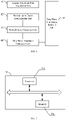
- FIG. 5 is a schematic diagram of a computer device according to an embodiment of the present disclosure.
- the computer device 50 includes a memory 501, a processor 502, and a computer program stored in the memory 501 and executable on the processor 502.
- the processor 502 is configured to execute the computer program to implement any one of the embodiments of the method for removing tube wave interference from optical fiber acoustic wave sensing seismic data.
- an embodiment of the present disclosure further provides a computer-readable storage medium to solve the technical problem that the conventional methods for removing tube wave interference from optical fiber acoustic wave sensing seismic data cannot completely remove the tube wave interference and may easily filter out valid signals.
- the computer-readable storage medium stores a computer program for implementing any one of the embodiments of the method for removing tube wave interference from optical fiber acoustic wave sensing seismic data.
- the embodiments of the present disclosure provide a method and an apparatus for removing tube wave interference from optical fiber acoustic wave sensing seismic data, a computer device and a computer-readable storage medium.
- Optical fibers are suspended in a borehole, and explosives or vibroseis are used as excitation sources, so as to obtain seismic wavefield data collected by the optical fibers.
- a root-mean-square amplitude analysis is carried out on the seismic wavefield data along a time window of a tube wave, to determine and calculate tube wave energy as a tube wave normalization factor.
- the present disclosure can greatly improve a signal-to-noise ratio of the seismic data collected by the optical fibers. According to the embodiments of the present disclosure, it is possible to improve the signal-to-noise ratio of the data collected by the optical fibers by denoising, highlight the wavefield propagating along the stratum, and improve the application effect of the optical fiber sensing technology in collecting data during the seismic exploration.
- any embodiment of the present disclosure can be provided as a method, a system, or a computer program product. Therefore, the present disclosure can take the form of a full hardware embodiment, a full software embodiment, or an embodiment combining software and hardware. Moreover, the present invention can take the form of a computer program product implemented on one or more computer usable storage mediums (including, but not limited to, a magnetic disc memory, CD-ROM, optical storage, etc.) containing therein computer usable program codes.
- a computer usable storage mediums including, but not limited to, a magnetic disc memory, CD-ROM, optical storage, etc.
- each flow and/or block in the flow diagram and/or the block diagram and a combination of flows and/or blocks in the flow diagram and/or the block diagram can be realized by computer program instructions.
- Those computer program instructions can be provided to a general computer, a dedicated computer, an embedded processor or a processor of other programmable data processing device to produce a machine, so that the instructions executed by the processor of the computer or other programmable data processing device produce means for realizing specified functions in one or more flows in the flow diagram and/or one or more blocks in the block diagram.
- These computer program instructions can also be stored in a computer readable memory capable of directing the computer or other programmable data processing devices to operate in a specific manner, such that the instructions stored in the computer readable memory generate a manufactured article including an instruction device that implements the function(s) designated in one flow or a plurality of flows in the flow diagram and/or a block or a plurality of blocks in the block diagram.
- These computer program instructions can also be loaded onto a computer or other programmable data processing devices, such that a series of operation steps is executed on the computer or other programmable devices to generate the processing realized by the computer, therefore the instructions executed on the computer or other programmable devices provide the steps for implementing the function designated in one flow or a plurality of flows in the flow chart and/or a block or a plurality of blocks in the block diagram.
Landscapes
- Physics & Mathematics (AREA)
- Life Sciences & Earth Sciences (AREA)
- Engineering & Computer Science (AREA)
- Remote Sensing (AREA)
- Acoustics & Sound (AREA)
- Environmental & Geological Engineering (AREA)
- Geology (AREA)
- General Life Sciences & Earth Sciences (AREA)
- General Physics & Mathematics (AREA)
- Geophysics (AREA)
- Geophysics And Detection Of Objects (AREA)
- Measurement Of Mechanical Vibrations Or Ultrasonic Waves (AREA)
Abstract
Description
- The present disclosure relates to the field of geophysical explorations, and particularly to a method and an apparatus for removing tube wave interference from optical fiber acoustic wave sensing seismic data.
- With the rapid development, the optical fiber acoustic wave sensing technology is increasingly widely applied in borehole seismic explorations. Compared with the conventional geophone acquisition, the optical fiber acoustic wave sensing technology has the characteristics such as high-density sampling and high-temperature and high-pressure resistance. The optical fiber acoustic wave sensing technology mainly utilizes Rayleigh backscattering generated by laser light propagating in optical fibers. When the medium around the optical fibers vibrates, the Rayleigh scattering will change correspondingly. Through a continuous observation and demodulation of such optical signal, seismic wave information of a stratum can be obtained.
- Optical fiber acoustic wave sensing is suitable for observing seismic waves in a well. When the optical fibers are suspended in the well, tube wave interference is generated abnormally because of an incomplete coupling between the optical fibers and the borehole wall of the well, and a change in a distance between the optical fibers and the borehole wall causes tube wave energy to vary greatly, which seriously affects the receiving effect of the seismic waves. It is difficult to effectively remove the tube wave interference in the application of the optical fiber acoustic wave sensing technology in the seismic exploration.
- The prior art mainly adopts two methods to remove tube wave interference from optical fiber acoustic wave sensing seismic data. One method is a median filtering method including: picking up a relatively accurate first arrival of a tube wave, and performing median filtering based on the first arrival of the tube wave. However, this method changes an energy relationship and phase of original seismic wavefield data while filtering out the tube wave, and there are still some strong tube waves in seismic wave records after the filtering. The other method is a frequency-wavenumber domain filtering method including: transforming original seismic wavefield data to obtain a frequency-wavenumber spectrum thereof, selecting an apparent velocity range of the tube wave, and clearing the frequency-wavenumber spectrum within the apparent velocity range. However, this method cannot filter out the tube wave corresponding to a spatial alias frequency, so it is difficult to effectively remove the tube wave interference.
- As can be seen from the above analysis, the conventional methods for removing tube wave interference from optical fiber acoustic wave sensing seismic data have the technical problems that the tube wave interference cannot be completely removed and valid signals may be easily filtered out.
- The embodiments of the present disclosure provide a method for removing tube wave interference from optical fiber acoustic wave sensing seismic data to solve the technical problem that the conventional methods for removing tube wave interference from optical fiber acoustic wave sensing seismic data cannot completely remove the tube wave interference and may easily filter out valid signals. The method includes: acquiring seismic wavefield data which contains atube wave interference and is collected by an optical fiber acoustic wave sensing instrument, in which the seismic wavefield data comprises amplitude values at each sampling time point of seismic traces excited by a single shot; downwardly cutting waveform data with a preset time window length on each seismic trace along travel time of the tube wave, and calculating a root-mean-square amplitude of the waveform data cut on the seismic trace as an amplitude normalization factor of the seismic trace; performing normalization processing on the amplitude value of each seismic trace at each sampling time point based on the amplitude normalization factor of each seismic trace, to obtain a normalized amplitude value of the seismic trace at each sampling time point; performing de-tail mean filtering processing on the normalized amplitude value of each seismic trace at each sampling time point along the travel time of the tube wave, to obtain a predicted amplitude value of the tube wave at the sampling time point; and performing tube wave interference removal processing on each seismic trace at each sampling time point based on the predicted amplitude value of the tube wave at the sampling time point, and performing inverse normalization processing on the seismic trace at the sampling time point using the amplitude normalization factor of the seismic trace, so as to obtain the seismic wavefield data without tube wave interference.
- The embodiments of the present disclosure provide an apparatus for removing tube wave interference from optical fiber acoustic wave sensing seismic data to solve the technical problem that the conventional methods for removing tube wave interference from optical fiber acoustic wave sensing seismic data cannot completely remove the tube wave interference and may easily filter out valid signals. The apparatus includes: a seismic wavefield data acquisition unit configured to acquire seismic wavefield data which contains a tube wave interference and is collected by an optical fiber acoustic wave sensing instrument, in which the seismic wavefield data comprises amplitude values at each sampling time point of seismic traces excited by a single shot; a normalization factor determination unit configured to downwardly cut waveform data with a preset time window length on each seismic trace along travel time of a tube wave, and calculate a root-mean-square amplitude of the waveform data cut on the seismic trace as an amplitude normalization factor of the seismic trace; a normalization processing unit configured to perform normalization processing on the amplitude value of each seismic trace at each sampling time point based on the amplitude normalization factor of the seismic trace, to obtain a normalized amplitude value of the seismic trace at each sampling time point; a tube wave amplitude prediction unit configured to perform de-tail mean filtering processing on the normalized amplitude value of each seismic trace at each sampling time point along the travel time of the tube wave, to obtain a predicted amplitude value of the tube wave at the sampling time point; and a tube wave interference removal unit configured to perform tube wave interference removal processing on each seismic trace at each sampling time point based on the predicted amplitude value of the tube wave at the sampling time point, and perform inverse normalization processing on the seismic trace at the sampling time point using the amplitude normalization factor of the seismic trace to obtain the seismic wavefield data without tube wave interference.
- The embodiments of the present disclosure provide a computer device to solve the technical problem that the conventional methods for removing tube wave interference from optical fiber acoustic wave sensing seismic data cannot completely remove the tube wave interference and may easily filter out valid signals. The computer device includes: a memory, a processor and a computer program stored in the memory and executable on the processor, in which the processor is configured to execute the computer program to implement the aforementioned method for removing tube wave interference from optical fiber acoustic wave sensing seismic data.
- The embodiments of the present disclosure provide a computer-readable storage medium to solve the technical problem that the conventional methods for removing tube wave interference from optical fiber acoustic wave sensing seismic data cannot completely remove the tube wave interference and may easily filter out valid signals. The computer-readable storage medium stores a computer program for implementing the aforementioned method for removing tube wave interference from optical fiber acoustic wave sensing seismic data.
- Based on the characteristics that the tube wave interference in the optical fiber acoustic wave sensing seismic data has a relatively stable wave velocity, and the amplitude of the tube wave inversely proportional to the degree of coupling between the optical fibers and the borehole wall of the well, the embodiments of the present disclosure acquire seismic wavefield data which contains a tube wave interference and is collected by an optical fiber acoustic wave sensing instrument; downwardly cut waveform data with a preset time window length on each seismic trace along travel time of the tube wave, and calculate a root-mean-square amplitude of the waveform data cut on the seismic trace as an amplitude normalization factor of each seismic trace; perform normalization processing on the amplitude value of each seismic trace at each sampling time point based on the amplitude normalization factor of the seismic trace; perform de-tail mean filtering processing on the normalized result of the amplitude value of each seismic trace at each sampling time point along the travel time of the tube wave, to obtain a predicted amplitude value of the tube wave at each sampling time point; and perform tube wave interference removal processing on each seismic trace at each sampling time point based on the predicted amplitude value of the tube wave at the sampling time point, and perform inverse normalization processing using the amplitude normalization factor of the seismic trace to obtain the seismic wavefield data without tube wave interference.
- Through the embodiments of the present disclosure, it can effectively suppress the tube wave interference in the optical fiber acoustic wave sensing seismic data, improve the signal-to-noise ratio of the seismic wavefield data collected by the optical fiber acoustic wave sensing instrument, highlight the seismic signals propagating along the stratum, and improve the application effect of the optical fiber sensing technology in collecting the seismic data during the seismic exploration.
- For a clearer illustration of technical features in the embodiments of the present disclosure or in the prior art, a brief description of the drawings required for describing the embodiments or the prior art will be given below. Obviously, the drawings in the following description merely illustrate some embodiments of the present disclosure, and those of ordinary skill in the art can derive other drawings from them without any inventive efforts. In the drawings:
-
FIG. 1 is a flowchart of a method for removing tube wave interference from optical fiber acoustic wave sensing seismic data according to an embodiment of the present disclosure; -
FIG. 2 is a schematic diagram of a single shot record of optical fiber acoustic wave sensing seismic data before tube wave interference is removed according to an embodiment of the present disclosure; -
FIG. 3 is a schematic diagram of a single shot record of optical fiber acoustic wave sensing seismic data after the tube wave interference is removed according to an embodiment of the present disclosure; -
FIG. 4 is a schematic diagram of an apparatus for removing tube wave interference from optical fiber acoustic wave sensing seismic data according to an embodiment of the present disclosure; and -
FIG. 5 is a schematic diagram of a computer device according to an embodiment of the present disclosure. - For a clearer understanding of the objectives, technical features and effects of the present disclosure, the embodiments of the present disclosure will be further described in detail as follows with reference to the drawings. Here, the illustrative embodiments of the present disclosure and the descriptions thereof are intended to explain the present disclosure, rather than limitations to the present disclosure.
- In the description of this specification, words such as 'include', 'comprise', 'have' and 'contain' are all open terms, which mean including but not limited to. The description of the reference terms such as 'one embodiment', 'one specific embodiment', 'some embodiments' and 'for example' means that the specific features, structures or characteristics described in connection with the embodiment(s) or example(s) are included in at least one embodiment or example of the present disclosure. In this specification, the schematic expressions of the above terms do not necessarily refer to a same embodiment or example. In addition, the described specific features, structures or characteristics may be combined in any one or more embodiments or examples in a suitable manner. The sequence of steps involved in each embodiment is used to schematically illustrate the implementation of the present disclosure, and the sequence of steps is not limited, but can be appropriately adjusted as needed.
- An embodiment of the present disclosure provides a method for removing tube wave interference from optical fiber acoustic wave sensing seismic data.
FIG. 1 is a flowchart of a method for removing tube wave interference from optical fiber acoustic wave sensing seismic data according to an embodiment of the present disclosure. As illustrated inFIG. 1 , the method includes: - S101: acquiring seismic wavefield data which contains a tube wave and is collected by an optical fiber acoustic wave sensing instrument, wherein the seismic wavefield data comprises amplitude values at each sampling time point of seismic traces excited by a single shot.
- It should be noted that the optical fiber acoustic wave sensing is suitable for observing seismic waves in a well, and when being suspended in the well, optical fibers are more likely to receive tube wave interference because of an incomplete coupling between the optical fibers and the borehole wall of the well. The tube wave interference has a relatively stable wave velocity, and the amplitude value of the tube wave is inversely proportional to the coupling degree of the optical fibers (i.e., a degree of coupling between the optical fibers and the borehole wall), that is, the amplitude value of the tube wave increases as the distance between the optical fibers and the borehole wall increases (i.e., the coupling degree of the optical fibers decreases), and vice versa.
- Optionally, an excitation source for exciting the seismic wavefield data in the embodiment of the present disclosure may be explosives or artificial vibroseis. For example, single-shot or multi-shot seismic data is obtained by excitation of the explosives or vibroseis, an optical fiber acoustic wave sensor of an optical fiber acoustic wave collection instrument is suspended in a borehole by optical fibers, and seismic wavefield data including tube wave interference is acquired by the optical fiber acoustic wave sensing instrument.
- It should be noted that the seismic wavefield data collected by the optical fiber acoustic wave sensing instrument in S101 at least includes amplitude values at each sampling time point of seismic traces excited by a single shot. When the tube wave interference is removed from the multi-shot seismic wavefield data collected by the optical fiber acoustic wave sensing instrument, it is only necessary to repeatedly perform S102 to S105.
- S102: downwardly cutting waveform data with a preset time window length on each seismic trace along travel time of a tube wave, and calculating a root-mean-square amplitude of the waveform data cut on the seismic trace as an amplitude normalization factor of the seismic trace.
- Since the tube wave interference contained in the seismic data collected by the optical fibers has a relatively stable wave velocity, it appears as an oblique line in the single shot record of the seismic data. Thus, waveform data with a preset time window length is downwardly cut on each seismic trace along the oblique line, and a root-mean-square amplitude of the waveform data cut on the seismic trace is calculated as an amplitude normalization factor of the seismic trace. According to the embodiment of the present disclosure, a root-mean-square amplitude analysis is carried out along a time window of the tube wave, and a root-mean-square amplitude of waveform data with a preset time window length cut on each seismic trace is calculated. The root-mean-square amplitude can reflect tube wave energy and can be used as a normalized correction factor for the amplitude of each seismic trace, so as to remove the tube wave interference more effectively.
- Optionally, the preset time window length adopted in the embodiment of the present disclosure may be 2 to10 times of a dominant period of the tube wave.
- It should be noted that the root-mean-square amplitude refers to a mean square value of amplitudes corresponding to sampling time points within one preset time window length, and it may be calculated using the following formula:

- S103: performing normalization processing on the amplitude value of each seismic trace at each sampling time point based on the amplitude normalization factor of the seismic trace, to obtain a normalized amplitude value of the seismic trace at the sampling time point.
- It should be noted that in the embodiment of the present disclosure, when the normalization processing is performed on the amplitudes of each seismic trace in S103, it may, but not limited to, divide the amplitude value of each seismic trace at each sampling time point by the amplitude normalization factor of the seismic trace, to obtain the normalized amplitude value of the seismic trace at each sampling time point.
- S104: performing de-tail mean filtering processing on the normalized amplitude value of each seismic trace at each sampling time point along the travel time of the tube wave, to obtain a predicted amplitude value of the tube wave at the sampling time point.
- In one embodiment, S104 may be implemented by sorting the normalized amplitude values of the seismic traces at each sampling time point along a direction of the travel time of the tube wave, removing the first n normalized amplitude values and the last n normalized amplitude values, and performing a mean value calculation on the remaining normalized amplitude values to obtain a predicted amplitude value of the tube wave at each sampling time point, where n is a positive integer.
- It should be noted that, during the implementation, after the amplitude values corresponding to each sampling time point are sorted in S104, the number of the data in the front to be removed may be the same as or different from the number of the data in the rear to be removed. Generally, the value of n is less than half of a total number of the seismic traces. Optionally, the value range of n is from 5 to 15. For example, in a case where the number of the data to be processed by the de-tail mean filtering is 11, 3 first data or 3 last data in the sorting may be removed, i.e., n=3.
- S105: performing tube wave interference removal processing on each seismic trace at each sampling time point based on the predicted amplitude value of the tube wave at the sampling time point, and performing inverse normalization processing on the seismic trace at the sampling time point using the amplitude normalization factor of the seismic trace, so as to obtain the seismic wavefield data without tube wave interference.
- It should be noted that, when the normalization processing is performed in S103, it is possible to divide the amplitude value at each sampling time point of each seismic trace by the amplitude normalization factor of the seismic trace, to obtain the normalized amplitude value of the seismic trace at the sampling time point. Correspondingly, during the implementation of S105, it is possible to subtract the predicted amplitude value of the tube wave at each sampling time point from the normalized amplitude value at the sampling time point of each seismic trace to obtain a result, and multiply the result by the amplitude normalization factor of the seismic trace to obtain the seismic wavefield data without tube wave interference.
- As can be seen from the above, based on the characteristics that the tube wave interference in the optical fiber acoustic wave sensing seismic data has a relatively stable wave velocity (i.e., an event is linear in terms of waveform), and the amplitude of the tube wave inversely proportional to the degree of coupling between the optical fibers and the borehole wall of the well, the method for removing tube wave interference from optical fiber acoustic wave sensing seismic data according to the embodiments of the present disclosure acquires seismic wavefield data which contains tube wave interference and is collected by an optical fiber acoustic wave sensing instrument; downwardly cut waveform data with a preset time window length on each seismic trace along travel time of a tube wave, and calculates a root-mean-square amplitude of the waveform data cut on the seismic trace as an amplitude normalization factor of the seismic trace; performs normalization processing on the amplitude value at each sampling time point of each seismic trace based on the amplitude normalization factor of the seismic trace; performs de-tail mean filtering processing on the normalized result of the amplitude value of each seismic trace at each sampling time point along the travel time of the tube wave, to obtain a predicted amplitude value of each tube wave at each sampling time point; and performs tube wave interference removal processing on each seismic trace at each sampling time point based on the predicted amplitude value of the tube wave at the sampling time point, and performs inverse normalization processing using the amplitude normalization factor of the seismic trace to obtain the seismic wavefield data without tube wave interference.
- Through the method for removing tube wave interference from optical fiber acoustic wave sensing seismic data according to the embodiments of the present disclosure, it can effectively suppress the tube wave interference in the optical fiber acoustic wave sensing seismic data, improve the signal-to-noise ratio of the seismic wavefield data collected by the optical fiber acoustic wave sensing instrument, highlight the seismic signals propagating along the stratum, and improve the application effect of the optical fiber sensing technology in collecting the seismic data during the seismic exploration.
- Optionally, in the solution provided by the embodiments of the present disclosure based on S101~S105, the tube wave interference may be suppressed for the seismic data collected by the optical fibers in the following steps:
- 1) Using an optical fiber acoustic wave sensing collection instrument, suspending optical fibers in the well for reception, exciting on the ground or in the well by an explosion source or artificial vibroseis, or adopting a passive reception during a microseismic collection, so as to collect seismic wavefield data.
- 2) Preprocessing the seismic wavefield data collected in step 1), picking up travel time of the tube wave along a strong tube wave event, downwardly cutting data with a time window length of Lw , and calculating root-mean-square amplitudes within the time window length, to obtain a root-mean-square amplitude Ai as an amplitude normalization factor of an i-th seismic trace.
Optionally, the time window length is determined based on a dominant period D of the tube wave, and is generally 2 to 10 times of the period D. For example, Lw = 100 ms. - 3) Using the amplitude normalization factor of each seismic trace determined in step 2) to divide the amplitude at each sampling time point of each seismic trace in the collected seismic wavefield data by the normalization factor Ai of the seismic trace, and performing de-tail mean filtering and calculating of amplitudes of each seismic trace at each sampling time point along the picked up travel time of the tube wave, to obtain the amplitude value of the tube wave interference at the sampling time point.
It should be noted that in the embodiment of the present disclosure, the de-tail mean filtering processing means using the input seismic trace to sort amplitudes of seismic traces at each sampling time point along the picked-up travel time, removing the largest n normalized amplitude values and the smallest n normalized amplitude values, and calculating a mean value of the remaining normalized amplitude values as a predicted output value of the tube wave interference at each sampling time point. Here, the value of n is generally less than half of the number of the counted traces, and the minimum value of n is 0, which is equivalent to mean filtering. - 4) Using the amplitude value of the predicted tube wave interference at each sampling time point obtained through the de-tail mean filtering in step 3) to process all the input seismic traces in the current seismic data record by a subtraction method, and then multiplying each output seismic trace by the normalization factor Ai to obtain the seismic data record without tube wave interference.
Through step 2) to step 4), the single shot seismic data record is denoised, and all the seismic records with tube wave interference are denoised by repeating step 2) to step 4). - 5) Using the seismic data collected by the optical fibers with tube wave interference suppressed in 4) for subsequent processing and interpretation, so as to provide geophysical result data available for geological researches.
- By using the method for removing tube wave interference from optical fiber acoustic wave sensing seismic data according to the embodiments of the present disclosure, the tube wave interference in the borehole seismic data collected by the optical fibers can be suppressed and removed to a large extent, and the data quality can be significantly improved, which provides a guarantee for subsequent seismic data processing and interpretation.
- Using the method for removing tube wave interference from optical fiber acoustic wave sensing seismic data according to the embodiments of the present disclosure, seismic data of an actual optical fiber collection in an oil well in North China is processed.
FIG. 2 illustrates a single shot record of optical fiber acoustic wave sensing seismic data before tube wave interference is removed; andFIG. 3 illustrates a single shot record of optical fiber acoustic wave sensing seismic data after the tube wave interference is removed. - Based on the same inventive concept, an embodiment of the present disclosure further provides an apparatus for removing tube wave interference from optical fiber acoustic wave sensing seismic data, as described in the following embodiment. Since the principle of technical solution of the apparatus is similar to that of the method for removing tube wave interference from optical fiber acoustic wave sensing seismic data, the method as described above may be referred to for implementation of the apparatus, and the repetitive description is omitted herein.
-
FIG. 4 is a schematic diagram of an apparatus for removing tube wave interference from optical fiber acoustic wave sensing seismic data according to an embodiment of the present disclosure. As illustrated inFIG. 4 , the apparatus may include a seismic wavefielddata acquisition unit 41, a normalizationfactor determination unit 42, anormalization processing unit 43, a tube waveamplitude prediction unit 44 and a tube waveinterference removal unit 45. - In which, the seismic wavefield data acquisition unit 41 is configured to acquire seismic wavefield data which contains a tube wave interference and is collected by an optical fiber acoustic wave sensing instrument, wherein the seismic wavefield data comprises amplitude values at each sampling time point of seismic traces excited by a single shot; the normalization factor determination unit 42 is configured to downwardly cut waveform data with a preset time window length on each seismic trace along travel time of a tube wave, and calculate a root-mean-square amplitude of the waveform data cut on the seismic trace as an amplitude normalization factor of the seismic trace; the normalization processing unit 43 is configured to perform normalization processing on the amplitude value at each sampling time point of each seismic trace based on the amplitude normalization factor of the seismic trace, to obtain a normalized amplitude value of the seismic trace at the sampling time point; the tube wave amplitude prediction unit 44 is configured to perform de-tail mean filtering processing on the normalized amplitude value at each sampling time point of each seismic trace along the travel time of the tube wave, to obtain a predicted amplitude value of the tube wave at the sampling time point; and the tube wave interference removal unit 45 is configured to perform tube wave interference removal processing on each seismic trace at each sampling time point based on the predicted amplitude value of the tube wave at the sampling time point, and perform inverse normalization processing on the seismic trace at the sampling time point using the amplitude normalization factor of the seismic trace, so as to obtain the seismic wavefield data without tube wave interference.
- Optionally, the preset time window length is 2 to 10 times of a dominant period of the tube wave.
- As can be seen from the above, in the apparatus for removing tube wave interference from optical fiber acoustic wave sensing seismic data according to the embodiments of the present disclosure, the seismic wavefield data acquisition unit 41 acquires seismic wavefield data which contains the tube wave and is collected by an optical fiber acoustic wave sensing instrument; the normalization factor determination unit 42 downwardly cut waveform data with a preset time window length on each seismic trace along travel time of a tube wave, and calculates a root-mean-square amplitude of the waveform data cut on the seismic trace as an amplitude normalization factor of the seismic trace; the normalization processing unit 43 performs normalization processing on the amplitude value at each sampling time point of each seismic trace based on the amplitude normalization factor of the seismic trace; the tube wave amplitude prediction unit 44 performs detail mean filtering processing on the normalized result of the amplitude value at each sampling time point of each seismic trace along the travel time of the tube wave, to obtain a predicted amplitude value at each sampling time point of tube wave; and the tube wave interference removal unit 45 performs tube wave interference removal processing on each seismic trace at each sampling time point based on the predicted amplitude value of the tube wave at the sampling time point, and performs inverse normalization processing using the amplitude normalization factor of the seismic trace to obtain the seismic wavefield data without tube wave interference.
- Through the apparatus for removing tube wave interference from optical fiber acoustic wave sensing seismic data according to the embodiments of the present disclosure, it can effectively suppress the tube wave interference in the optical fiber acoustic wave sensing seismic data, improve the signal-to-noise ratio of the seismic wavefield data collected by the optical fiber acoustic wave sensing instrument, highlight the seismic signals propagating along the stratum, and improve the application effect of the optical fiber sensing technology in collecting the seismic data during the seismic exploration.
- In an optional embodiment, in the apparatus for removing tube wave interference from optical fiber acoustic wave sensing seismic data according to the embodiment of the present disclosure, the tube wave
amplitude prediction unit 44 is further configured to sort the normalized amplitude values of the seismic traces at each sampling time point along a direction of the travel time of the tube wave, remove the first n normalized amplitude values and the last n normalized amplitude values, and perform a mean value calculation on the remaining normalized amplitude values to obtain the predicted amplitude value of the tube wave at the sampling time point, where n is a positive integer. Optionally, a value of n is less than half of a total number of the seismic traces. - In an optional embodiment, in the apparatus for removing tube wave interference from optical fiber acoustic wave sensing seismic data according to the embodiment of the present disclosure, the normalization
factor determination unit 42 is further configured to divide the amplitude value at each sampling time point of each seismic trace by the amplitude normalization factor of the seismic trace, to obtain the normalized amplitude value of the seismic trace at the sampling time point; and the tube waveinterference removal unit 45 is further configured to subtract the predicted amplitude value of the tube wave at each sampling time point from the normalized amplitude value at the sampling time point of each seismic trace to obtain a result, and multiply the result by the amplitude normalization factor of the seismic trace to obtain the seismic wavefield data without tube wave interference. - Based on the same inventive concept, an embodiment of the present disclosure further provides a computer device to solve the technical problem that the conventional methods for removing tube wave interference from optical fiber acoustic wave sensing seismic data cannot completely remove the tube wave interference and may easily filter out valid signals.
FIG. 5 is a schematic diagram of a computer device according to an embodiment of the present disclosure. As illustrated inFIG. 5 , thecomputer device 50 includes amemory 501, aprocessor 502, and a computer program stored in thememory 501 and executable on theprocessor 502. Theprocessor 502 is configured to execute the computer program to implement any one of the embodiments of the method for removing tube wave interference from optical fiber acoustic wave sensing seismic data. - Based on the same inventive concept, an embodiment of the present disclosure further provides a computer-readable storage medium to solve the technical problem that the conventional methods for removing tube wave interference from optical fiber acoustic wave sensing seismic data cannot completely remove the tube wave interference and may easily filter out valid signals. The computer-readable storage medium stores a computer program for implementing any one of the embodiments of the method for removing tube wave interference from optical fiber acoustic wave sensing seismic data.
- To sum up, the embodiments of the present disclosure provide a method and an apparatus for removing tube wave interference from optical fiber acoustic wave sensing seismic data, a computer device and a computer-readable storage medium. Optical fibers are suspended in a borehole, and explosives or vibroseis are used as excitation sources, so as to obtain seismic wavefield data collected by the optical fibers. A root-mean-square amplitude analysis is carried out on the seismic wavefield data along a time window of a tube wave, to determine and calculate tube wave energy as a tube wave normalization factor. After all seismic traces are subjected to a normalized correction, an amplitude of the tube wave at each time point is calculated by de-tail mean filtering along travel time of tube wave, and then the tube wave is removed by a subtraction method. Next, a denoised seismic wavefield is recovered using the normalization factor. Therefore, the present disclosure can greatly improve a signal-to-noise ratio of the seismic data collected by the optical fibers. According to the embodiments of the present disclosure, it is possible to improve the signal-to-noise ratio of the data collected by the optical fibers by denoising, highlight the wavefield propagating along the stratum, and improve the application effect of the optical fiber sensing technology in collecting data during the seismic exploration.
- Those skilled in the art should appreciate that any embodiment of the present disclosure can be provided as a method, a system, or a computer program product. Therefore, the present disclosure can take the form of a full hardware embodiment, a full software embodiment, or an embodiment combining software and hardware. Moreover, the present invention can take the form of a computer program product implemented on one or more computer usable storage mediums (including, but not limited to, a magnetic disc memory, CD-ROM, optical storage, etc.) containing therein computer usable program codes.
- The present disclosure is described with reference to a flow diagram and/or a block diagram of the method, device (system) and computer program product according to the embodiments of the present disclosure. It should be appreciated that each flow and/or block in the flow diagram and/or the block diagram and a combination of flows and/or blocks in the flow diagram and/or the block diagram can be realized by computer program instructions. Those computer program instructions can be provided to a general computer, a dedicated computer, an embedded processor or a processor of other programmable data processing device to produce a machine, so that the instructions executed by the processor of the computer or other programmable data processing device produce means for realizing specified functions in one or more flows in the flow diagram and/or one or more blocks in the block diagram.
- These computer program instructions can also be stored in a computer readable memory capable of directing the computer or other programmable data processing devices to operate in a specific manner, such that the instructions stored in the computer readable memory generate a manufactured article including an instruction device that implements the function(s) designated in one flow or a plurality of flows in the flow diagram and/or a block or a plurality of blocks in the block diagram.
- These computer program instructions can also be loaded onto a computer or other programmable data processing devices, such that a series of operation steps is executed on the computer or other programmable devices to generate the processing realized by the computer, therefore the instructions executed on the computer or other programmable devices provide the steps for implementing the function designated in one flow or a plurality of flows in the flow chart and/or a block or a plurality of blocks in the block diagram.
- The above specific embodiments have further explained the objectives, technical solutions and advantageous effects of the present disclosure in detail. It should be appreciated that those described above are just specific embodiments of the present disclosure, and are not intended to limit the protection scope of the present disclosure. Any modification, equivalent substitution, improvement, etc. made within the spirit and principle of the present disclosure should fall within the protection scope of the present disclosure.
Claims (10)
- A method for removing tube wave interference from optical fiber acoustic wave sensing seismic data, comprising:acquiring seismic wavefield data which contains a tube wave interference and is collected by an optical fiber acoustic wave sensing instrument, wherein the seismic wavefield data comprises amplitude values at each sampling time point of seismic traces excited by a single shot;downwardly cutting waveform data with a preset time window length on each seismic trace along travel time of the tube wave, and calculating a root-mean-square amplitude of the waveform data cut on the seismic trace as an amplitude normalization factor of the seismic trace;performing normalization processing on the amplitude value of each seismic trace at each sampling time point based on the amplitude normalization factor of the seismic trace, to obtain a normalized amplitude value of the seismic trace at the sampling time point;performing de-tail mean filtering processing on the normalized amplitude value of each seismic trace at each sampling time point along the travel time of the tube wave, to obtain a predicted amplitude value of the tube wave at the sampling time point; andperforming tube wave interference removal processing on each seismic trace at each sampling time point based on the predicted amplitude value of the tube wave at the sampling time point, and performing inverse normalization processing on the seismic trace at the sampling time point using the amplitude normalization factor of the seismic trace, so as to obtain the seismic wavefield data without tube wave interference.
- The method according to claim 1, wherein performing the de-tail mean filtering processing on the normalized amplitude value of each seismic trace at each sampling time point along the travel time of the tube wave, to obtain a predicted amplitude value of the tube wave at the sampling time point, comprising:
sorting the normalized amplitude values of the seismic traces at each sampling time point along a direction of the travel time of the tube wave, removing the first n normalized amplitude values and the last n normalized amplitude values, and performing a mean value calculation on the remaining normalized amplitude values to obtain the predicted amplitude value of the tube wave at the sampling time point, where n is a positive integer. - The method according to claim 2, wherein a value of n is less than half of a total number of the seismic traces.
- The method according to claim 1, wherein,performing the normalization processing on the amplitude value of each seismic trace at each sampling time point based on the amplitude normalization factor of the seismic trace, to obtain the normalized amplitude value of the seismic trace at the sampling time point, comprising: dividing the amplitude value of each seismic trace at each sampling time point by the amplitude normalization factor of the seismic trace, to obtain the normalized amplitude value at the sampling time point of the seismic trace;performing the tube wave interference removal processing on each seismic trace at each sampling time point based on the predicted amplitude value of the tube wave at the sampling time point, and performing the inverse normalization processing on the seismic trace at the sampling time point using the amplitude normalization factor of the seismic trace to obtain the seismic wavefield data without the tube wave interference, comprising: subtracting the predicted amplitude value of the tube wave at each sampling time point from the normalized amplitude value of each seismic trace at the sampling time point to obtain a result, and multiplying the result by the amplitude normalization factor of the seismic trace to obtain the seismic wavefield data without the tube wave interference.
- The method according to any one of claims 1 to 4, wherein the preset time window length is 2 to 10 times of a dominant period of the tube wave.
- An apparatus for removing tube wave interference from optical fiber acoustic wave sensing seismic data, comprising:a seismic wavefield data acquisition unit configured to acquire seismic wavefield data which contains a tube wave interference and is collected by an optical fiber acoustic wave sensing instrument, wherein the seismic wavefield data comprises amplitude values at each sampling time point of seismic traces excited by a single shot;a normalization factor determination unit configured to downwardly cut waveform data with a preset time window length on each seismic trace along travel time of the tube wave, and calculate a root-mean-square amplitude of the waveform data cut on the seismic trace as an amplitude normalization factor of the seismic trace;a normalization processing unit configured to perform normalization processing on the amplitude value of each seismic trace at each sampling time point based on the amplitude normalization factor of the seismic trace, to obtain a normalized amplitude value of the seismic trace at the sampling time point;a tube wave amplitude prediction unit configured to perform de-tail mean filtering processing on the normalized amplitude value of each seismic trace at each sampling time point along the travel time of the tube wave, to obtain a predicted amplitude value of the tube wave at the sampling time point; anda tube wave interference removal unit configured to perform tube wave interference removal processing on each seismic trace at each sampling time point based on the predicted amplitude value of the tube wave at the sampling time point, and perform inverse normalization processing on the seismic trace at the sampling time point using the amplitude normalization factor of the seismic trace to obtain the seismic wavefield data without tube wave interference.
- The apparatus according to claim 6, wherein the tube wave amplitude prediction unit is further configured to sort the normalized amplitude values of the seismic traces at each sampling time point along a direction of the travel time of the tube wave, remove the first n normalized amplitude values and the last n normalized amplitude values, and perform a mean value calculation on the remaining normalized amplitude values to obtain a predicted amplitude value of the tube wave at the sampling time point, where n is a positive integer.
- The apparatus according to claim 6, wherein the normalization factor determination unit is further configured to divide the amplitude value of each seismic trace at each sampling time point by the amplitude normalization factor of the seismic trace, to obtain the normalized amplitude value of the seismic trace at the sampling time point; and the tube wave interference removal unit is further configured to subtract the predicted amplitude value of the tube wave at each sampling time point from the normalized amplitude value of each seismic trace at the sampling time point to obtain a result, and multiply the result by the amplitude normalization factor of the seismic trace to obtain the seismic wavefield data without tube wave interference.
- A computer device, comprising a memory, a processor and a computer program stored in the memory and executable on the processor, wherein the processor is configured to execute the computer program to implement the method for removing tube wave interference from optical fiber acoustic wave sensing seismic data according to any one of claims 1 to 5.
- A computer-readable storage medium storing a computer program for implementing the method for removing tube wave interference from optical fiber acoustic wave sensing seismic data according to any one of claims 1 to 5.
Applications Claiming Priority (2)
| Application Number | Priority Date | Filing Date | Title |
|---|---|---|---|
| CN202010080534.5A CN113219539B (en) | 2020-02-05 | 2020-02-05 | Method and device for removing borehole wave interference in optical fiber acoustic sensing seismic data |
| PCT/CN2021/074067 WO2021155754A1 (en) | 2020-02-05 | 2021-01-28 | Method and apparatus for removing tube wave interference from optical fiber acoustic wave sensing seismic data |
Publications (3)
| Publication Number | Publication Date |
|---|---|
| EP4102260A1 true EP4102260A1 (en) | 2022-12-14 |
| EP4102260A4 EP4102260A4 (en) | 2023-08-16 |
| EP4102260B1 EP4102260B1 (en) | 2024-11-06 |
Family
ID=77085498
Family Applications (1)
| Application Number | Title | Priority Date | Filing Date |
|---|---|---|---|
| EP21749991.2A Active EP4102260B1 (en) | 2020-02-05 | 2021-01-28 | Method and apparatus for removing tube wave interference from optical fiber acoustic wave sensing seismic data |
Country Status (4)
| Country | Link |
|---|---|
| US (1) | US12326533B2 (en) |
| EP (1) | EP4102260B1 (en) |
| CN (1) | CN113219539B (en) |
| WO (1) | WO2021155754A1 (en) |
Families Citing this family (6)
| Publication number | Priority date | Publication date | Assignee | Title |
|---|---|---|---|---|
| CN116413803A (en) * | 2021-12-29 | 2023-07-11 | 中国石油天然气集团有限公司 | Method and device for improving DAS signal-to-noise ratio by using local FK transformation |
| CN116416314B (en) * | 2021-12-30 | 2025-08-26 | 中国石油天然气集团有限公司 | Method and device for calibrating depth of optical fiber in well |
| CN114548156B (en) * | 2022-01-24 | 2023-05-12 | 成都理工大学 | Distributed optical fiber temperature measurement and noise reduction method based on downsampling and convolutional neural network |
| US20240012167A1 (en) * | 2022-07-05 | 2024-01-11 | Exfo Inc. | Method and apparatus of distributed acoustic sensing |
| CN117333575B (en) * | 2023-06-21 | 2024-05-31 | 广州海洋地质调查局 | Shaft distributed optical fiber acoustic vibration monitoring data imaging method and processing terminal |
| CN119575471B (en) * | 2023-09-07 | 2026-03-17 | 中国石油化工股份有限公司 | A data analysis method, apparatus, electronic device, and storage medium |
Family Cites Families (18)
| Publication number | Priority date | Publication date | Assignee | Title |
|---|---|---|---|---|
| US4715019A (en) * | 1986-01-27 | 1987-12-22 | Mobil Oil Corporation | Borehole logging method for determining the damping of acoustic tube waves in subsurface formations along a borehole wall |
| US5168470A (en) | 1992-01-23 | 1992-12-01 | Mobil Oil Corporation | Apparatus for rotating a transducer assembly of a borehole logging tool in a deviated borehole |
| FR2714486B1 (en) * | 1993-12-29 | 1996-01-26 | Inst Francais Du Petrole | Method and device for seismic prospecting in wells allowing filtering of guided waves. |
| US6724319B1 (en) * | 1999-10-29 | 2004-04-20 | Litton Systems, Inc. | Acoustic sensing system for downhole seismic applications utilizing an array of fiber optic sensors |
| CA2446270C (en) * | 2001-05-11 | 2013-03-05 | Shell Canada Limited | Removing irregularities from seismic data caused by tube waves |
| FR2831961B1 (en) * | 2001-11-07 | 2004-07-23 | Inst Francais Du Petrole | METHOD FOR PROCESSING SEISMIC DATA OF WELLS IN ABSOLUTE PRESERVED AMPLITUDE |
| CN1215424C (en) * | 2002-03-26 | 2005-08-17 | 周熙襄 | Handling method for eliminating strong correlated interference waves in seismic exploration recordings |
| CN102692650B (en) * | 2011-03-23 | 2014-10-29 | 中国石油天然气集团公司 | Wellbore wave separation method having false frequency pressing function |
| CN102778692B (en) | 2011-05-13 | 2014-12-31 | 中国石油天然气集团公司 | Method for determining quality factor by using seismic data |
| GB201112154D0 (en) * | 2011-07-15 | 2011-08-31 | Qinetiq Ltd | Seismic geophysical surveying |
| CN104216008B (en) | 2013-06-05 | 2017-02-08 | 中国石油天然气集团公司 | Downhole fracturing microseismic event identification method |
| CN104133247B (en) * | 2014-07-31 | 2017-01-25 | 中国石油天然气集团公司 | Suppressing method and device for sleeve waves in data of vertical seismic profile |
| CN107526107A (en) * | 2016-06-21 | 2017-12-29 | 中国石油化工股份有限公司 | The relevant noise attenuation method of amplitude and device by force |
| CN106154321B (en) * | 2016-07-20 | 2018-10-16 | 中国石油天然气集团公司 | The detection method and device of perforation signal |
| CA3042987A1 (en) * | 2016-12-02 | 2018-06-07 | Halliburton Energy Services, Inc. | Simulation of geophone data from distributed acoustic sensing data |
| CA3064870C (en) * | 2017-06-28 | 2021-12-28 | Halliburton Energy Services, Inc. | Angular response compensation for das vsp |
| CN108693561B (en) * | 2018-06-14 | 2019-11-08 | 中煤科工集团西安研究院有限公司 | Coal mining seismic acquisition system and method based on wave detector subdivision array |
| CN109557587B (en) * | 2018-12-28 | 2020-10-30 | 长江大学 | A kind of VSP seismic data wellbore wave frequency domain filtering method and device |
-
2020
- 2020-02-05 CN CN202010080534.5A patent/CN113219539B/en active Active
-
2021
- 2021-01-28 EP EP21749991.2A patent/EP4102260B1/en active Active
- 2021-01-28 WO PCT/CN2021/074067 patent/WO2021155754A1/en not_active Ceased
- 2021-01-28 US US17/797,708 patent/US12326533B2/en active Active
Also Published As
| Publication number | Publication date |
|---|---|
| CN113219539B (en) | 2022-08-30 |
| US20230072038A1 (en) | 2023-03-09 |
| EP4102260A4 (en) | 2023-08-16 |
| WO2021155754A1 (en) | 2021-08-12 |
| CN113219539A (en) | 2021-08-06 |
| US12326533B2 (en) | 2025-06-10 |
| EP4102260B1 (en) | 2024-11-06 |
Similar Documents
| Publication | Publication Date | Title |
|---|---|---|
| US12326533B2 (en) | Method and apparatus for removing tube wave interference from optical fiber acoustic wave sensing seismic data | |
| Egorov et al. | Elastic full-waveform inversion of vertical seismic profile data acquired with distributed acoustic sensors | |
| RU2694621C1 (en) | Method and apparatus for processing seismic data | |
| CN103616722B (en) | A first-arrival travel time picking method and device | |
| CN101551465B (en) | Method for adaptively recognizing and eliminating seismic exploration single-frequency interference | |
| Zhou et al. | An improved automatic picking method for arrival time of acoustic emission signals | |
| CN105116443B (en) | The energy compensation process and device of a kind of low frequency signal | |
| CN107144880A (en) | A kind of seismic wave wave field separation method | |
| CN113189641B (en) | Two-channel multi-mode Rayleigh wave underground detection system and method | |
| CN116338774A (en) | Downhole microseismic inversion method and system based on distributed optical fiber sensors | |
| Zhang et al. | An effective denoising method based on cumulative distribution function thresholding and its application in the microseismic signal of a metal mine with high sampling rate (6 kHz) | |
| CN107402405B (en) | Quiet phase virtual source trace gather construction method | |
| Oboué et al. | Protecting the weak signals in distributed acoustic sensing data processing using local orthogonalization: The FORGE data example | |
| CN113721296A (en) | Method and device for processing remote seismic data | |
| CN112379418A (en) | Method and system for calculating wave velocity of seismic direct arrival wave | |
| Zheng et al. | Microseismic event denoising via adaptive directional vector median filters | |
| CN112526611A (en) | Method and device for extracting surface seismic wave quality factor | |
| CN104570115B (en) | A kind of surface wave attenuation method and device | |
| CN117665930B (en) | A method and system for earthquake source location based on surface wave dispersion back propagation and superposition | |
| CN113126164B (en) | Seismic data denoising method and device | |
| GB2235534A (en) | Estimating velocities of seismic waves | |
| CN115826039B (en) | A time slice classification model training method, system and application method, system | |
| CN101907726B (en) | Method for automatically identifying and eliminating industrial electrical interference in earthquake exploration | |
| CN111965704B (en) | Optical cable secondary oscillation noise suppression method and system for well seismic data | |
| EP4095566B1 (en) | Method and apparatus for extracting downgoing wavelet and attenuation parameters by using vertical seismic data |
Legal Events
| Date | Code | Title | Description |
|---|---|---|---|
| STAA | Information on the status of an ep patent application or granted ep patent |
Free format text: STATUS: THE INTERNATIONAL PUBLICATION HAS BEEN MADE |
|
| PUAI | Public reference made under article 153(3) epc to a published international application that has entered the european phase |
Free format text: ORIGINAL CODE: 0009012 |
|
| STAA | Information on the status of an ep patent application or granted ep patent |
Free format text: STATUS: REQUEST FOR EXAMINATION WAS MADE |
|
| 17P | Request for examination filed |
Effective date: 20220831 |
|
| AK | Designated contracting states |
Kind code of ref document: A1 Designated state(s): AL AT BE BG CH CY CZ DE DK EE ES FI FR GB GR HR HU IE IS IT LI LT LU LV MC MK MT NL NO PL PT RO RS SE SI SK SM TR |
|
| DAV | Request for validation of the european patent (deleted) | ||
| DAX | Request for extension of the european patent (deleted) | ||
| A4 | Supplementary search report drawn up and despatched |
Effective date: 20230714 |
|
| RIC1 | Information provided on ipc code assigned before grant |
Ipc: G01V 1/50 20060101ALI20230710BHEP Ipc: G01V 1/22 20060101ALI20230710BHEP Ipc: G01V 1/36 20060101ALI20230710BHEP Ipc: G01V 1/48 20060101AFI20230710BHEP |
|
| GRAP | Despatch of communication of intention to grant a patent |
Free format text: ORIGINAL CODE: EPIDOSNIGR1 |
|
| STAA | Information on the status of an ep patent application or granted ep patent |
Free format text: STATUS: GRANT OF PATENT IS INTENDED |
|
| INTG | Intention to grant announced |
Effective date: 20240729 |
|
| GRAS | Grant fee paid |
Free format text: ORIGINAL CODE: EPIDOSNIGR3 |
|
| GRAA | (expected) grant |
Free format text: ORIGINAL CODE: 0009210 |
|
| STAA | Information on the status of an ep patent application or granted ep patent |
Free format text: STATUS: THE PATENT HAS BEEN GRANTED |
|
| AK | Designated contracting states |
Kind code of ref document: B1 Designated state(s): AL AT BE BG CH CY CZ DE DK EE ES FI FR GB GR HR HU IE IS IT LI LT LU LV MC MK MT NL NO PL PT RO RS SE SI SK SM TR |
|
| REG | Reference to a national code |
Ref country code: GB Ref legal event code: FG4D |
|
| REG | Reference to a national code |
Ref country code: CH Ref legal event code: EP |
|
| REG | Reference to a national code |
Ref country code: DE Ref legal event code: R096 Ref document number: 602021021449 Country of ref document: DE |
|
| REG | Reference to a national code |
Ref country code: IE Ref legal event code: FG4D |
|
| REG | Reference to a national code |
Ref country code: LT Ref legal event code: MG9D |
|
| REG | Reference to a national code |
Ref country code: NL Ref legal event code: MP Effective date: 20241106 |
|
| PG25 | Lapsed in a contracting state [announced via postgrant information from national office to epo] |
Ref country code: PT Free format text: LAPSE BECAUSE OF FAILURE TO SUBMIT A TRANSLATION OF THE DESCRIPTION OR TO PAY THE FEE WITHIN THE PRESCRIBED TIME-LIMIT Effective date: 20250306 Ref country code: HR Free format text: LAPSE BECAUSE OF FAILURE TO SUBMIT A TRANSLATION OF THE DESCRIPTION OR TO PAY THE FEE WITHIN THE PRESCRIBED TIME-LIMIT Effective date: 20241106 Ref country code: IS Free format text: LAPSE BECAUSE OF FAILURE TO SUBMIT A TRANSLATION OF THE DESCRIPTION OR TO PAY THE FEE WITHIN THE PRESCRIBED TIME-LIMIT Effective date: 20250306 |
|
| PG25 | Lapsed in a contracting state [announced via postgrant information from national office to epo] |
Ref country code: NL Free format text: LAPSE BECAUSE OF FAILURE TO SUBMIT A TRANSLATION OF THE DESCRIPTION OR TO PAY THE FEE WITHIN THE PRESCRIBED TIME-LIMIT Effective date: 20241106 Ref country code: FI Free format text: LAPSE BECAUSE OF FAILURE TO SUBMIT A TRANSLATION OF THE DESCRIPTION OR TO PAY THE FEE WITHIN THE PRESCRIBED TIME-LIMIT Effective date: 20241106 |
|
| REG | Reference to a national code |
Ref country code: AT Ref legal event code: MK05 Ref document number: 1739951 Country of ref document: AT Kind code of ref document: T Effective date: 20241106 |
|
| PG25 | Lapsed in a contracting state [announced via postgrant information from national office to epo] |
Ref country code: BG Free format text: LAPSE BECAUSE OF FAILURE TO SUBMIT A TRANSLATION OF THE DESCRIPTION OR TO PAY THE FEE WITHIN THE PRESCRIBED TIME-LIMIT Effective date: 20241106 |
|
| PG25 | Lapsed in a contracting state [announced via postgrant information from national office to epo] |
Ref country code: ES Free format text: LAPSE BECAUSE OF FAILURE TO SUBMIT A TRANSLATION OF THE DESCRIPTION OR TO PAY THE FEE WITHIN THE PRESCRIBED TIME-LIMIT Effective date: 20241106 |
|
| PG25 | Lapsed in a contracting state [announced via postgrant information from national office to epo] |
Ref country code: NO Free format text: LAPSE BECAUSE OF FAILURE TO SUBMIT A TRANSLATION OF THE DESCRIPTION OR TO PAY THE FEE WITHIN THE PRESCRIBED TIME-LIMIT Effective date: 20250206 |
|
| PG25 | Lapsed in a contracting state [announced via postgrant information from national office to epo] |
Ref country code: AT Free format text: LAPSE BECAUSE OF FAILURE TO SUBMIT A TRANSLATION OF THE DESCRIPTION OR TO PAY THE FEE WITHIN THE PRESCRIBED TIME-LIMIT Effective date: 20241106 Ref country code: LV Free format text: LAPSE BECAUSE OF FAILURE TO SUBMIT A TRANSLATION OF THE DESCRIPTION OR TO PAY THE FEE WITHIN THE PRESCRIBED TIME-LIMIT Effective date: 20241106 Ref country code: GR Free format text: LAPSE BECAUSE OF FAILURE TO SUBMIT A TRANSLATION OF THE DESCRIPTION OR TO PAY THE FEE WITHIN THE PRESCRIBED TIME-LIMIT Effective date: 20250207 |
|
| PG25 | Lapsed in a contracting state [announced via postgrant information from national office to epo] |
Ref country code: PL Free format text: LAPSE BECAUSE OF FAILURE TO SUBMIT A TRANSLATION OF THE DESCRIPTION OR TO PAY THE FEE WITHIN THE PRESCRIBED TIME-LIMIT Effective date: 20241106 |
|
| PG25 | Lapsed in a contracting state [announced via postgrant information from national office to epo] |
Ref country code: RS Free format text: LAPSE BECAUSE OF FAILURE TO SUBMIT A TRANSLATION OF THE DESCRIPTION OR TO PAY THE FEE WITHIN THE PRESCRIBED TIME-LIMIT Effective date: 20250206 |
|
| PG25 | Lapsed in a contracting state [announced via postgrant information from national office to epo] |
Ref country code: SM Free format text: LAPSE BECAUSE OF FAILURE TO SUBMIT A TRANSLATION OF THE DESCRIPTION OR TO PAY THE FEE WITHIN THE PRESCRIBED TIME-LIMIT Effective date: 20241106 |
|
| PG25 | Lapsed in a contracting state [announced via postgrant information from national office to epo] |
Ref country code: DK Free format text: LAPSE BECAUSE OF FAILURE TO SUBMIT A TRANSLATION OF THE DESCRIPTION OR TO PAY THE FEE WITHIN THE PRESCRIBED TIME-LIMIT Effective date: 20241106 |
|
| PG25 | Lapsed in a contracting state [announced via postgrant information from national office to epo] |
Ref country code: EE Free format text: LAPSE BECAUSE OF FAILURE TO SUBMIT A TRANSLATION OF THE DESCRIPTION OR TO PAY THE FEE WITHIN THE PRESCRIBED TIME-LIMIT Effective date: 20241106 |
|
| PG25 | Lapsed in a contracting state [announced via postgrant information from national office to epo] |
Ref country code: RO Free format text: LAPSE BECAUSE OF FAILURE TO SUBMIT A TRANSLATION OF THE DESCRIPTION OR TO PAY THE FEE WITHIN THE PRESCRIBED TIME-LIMIT Effective date: 20241106 |
|
| PG25 | Lapsed in a contracting state [announced via postgrant information from national office to epo] |
Ref country code: SK Free format text: LAPSE BECAUSE OF FAILURE TO SUBMIT A TRANSLATION OF THE DESCRIPTION OR TO PAY THE FEE WITHIN THE PRESCRIBED TIME-LIMIT Effective date: 20241106 |
|
| PG25 | Lapsed in a contracting state [announced via postgrant information from national office to epo] |
Ref country code: CZ Free format text: LAPSE BECAUSE OF FAILURE TO SUBMIT A TRANSLATION OF THE DESCRIPTION OR TO PAY THE FEE WITHIN THE PRESCRIBED TIME-LIMIT Effective date: 20241106 |
|
| PG25 | Lapsed in a contracting state [announced via postgrant information from national office to epo] |
Ref country code: IT Free format text: LAPSE BECAUSE OF FAILURE TO SUBMIT A TRANSLATION OF THE DESCRIPTION OR TO PAY THE FEE WITHIN THE PRESCRIBED TIME-LIMIT Effective date: 20241106 |
|
| REG | Reference to a national code |
Ref country code: DE Ref legal event code: R119 Ref document number: 602021021449 Country of ref document: DE |
|
| REG | Reference to a national code |
Ref country code: CH Ref legal event code: PL |
|
| PG25 | Lapsed in a contracting state [announced via postgrant information from national office to epo] |
Ref country code: SE Free format text: LAPSE BECAUSE OF FAILURE TO SUBMIT A TRANSLATION OF THE DESCRIPTION OR TO PAY THE FEE WITHIN THE PRESCRIBED TIME-LIMIT Effective date: 20241106 |
|
| PLBE | No opposition filed within time limit |
Free format text: ORIGINAL CODE: 0009261 |
|
| STAA | Information on the status of an ep patent application or granted ep patent |
Free format text: STATUS: NO OPPOSITION FILED WITHIN TIME LIMIT |
|
| PG25 | Lapsed in a contracting state [announced via postgrant information from national office to epo] |
Ref country code: LU Free format text: LAPSE BECAUSE OF NON-PAYMENT OF DUE FEES Effective date: 20250128 Ref country code: MC Free format text: LAPSE BECAUSE OF FAILURE TO SUBMIT A TRANSLATION OF THE DESCRIPTION OR TO PAY THE FEE WITHIN THE PRESCRIBED TIME-LIMIT Effective date: 20241106 |
|
| PG25 | Lapsed in a contracting state [announced via postgrant information from national office to epo] |
Ref country code: DE Free format text: LAPSE BECAUSE OF NON-PAYMENT OF DUE FEES Effective date: 20250801 |
|
| 26N | No opposition filed |
Effective date: 20250807 |
|
| PG25 | Lapsed in a contracting state [announced via postgrant information from national office to epo] |
Ref country code: BE Free format text: LAPSE BECAUSE OF NON-PAYMENT OF DUE FEES Effective date: 20250131 |
|
| PG25 | Lapsed in a contracting state [announced via postgrant information from national office to epo] |
Ref country code: CH Free format text: LAPSE BECAUSE OF NON-PAYMENT OF DUE FEES Effective date: 20250131 |
|
| REG | Reference to a national code |
Ref country code: BE Ref legal event code: MM Effective date: 20250131 |
|
| PGFP | Annual fee paid to national office [announced via postgrant information from national office to epo] |
Ref country code: GB Payment date: 20251211 Year of fee payment: 6 |
|
| PGFP | Annual fee paid to national office [announced via postgrant information from national office to epo] |
Ref country code: FR Payment date: 20251222 Year of fee payment: 6 |
|
| PG25 | Lapsed in a contracting state [announced via postgrant information from national office to epo] |
Ref country code: IE Free format text: LAPSE BECAUSE OF NON-PAYMENT OF DUE FEES Effective date: 20250128 |