EP4102240A1 - System, device and method for detecting connection of connecting structure - Google Patents
System, device and method for detecting connection of connecting structure Download PDFInfo
- Publication number
- EP4102240A1 EP4102240A1 EP20917399.6A EP20917399A EP4102240A1 EP 4102240 A1 EP4102240 A1 EP 4102240A1 EP 20917399 A EP20917399 A EP 20917399A EP 4102240 A1 EP4102240 A1 EP 4102240A1
- Authority
- EP
- European Patent Office
- Prior art keywords
- connection terminal
- contact point
- frequency
- resistance element
- connection
- Prior art date
- Legal status (The legal status is an assumption and is not a legal conclusion. Google has not performed a legal analysis and makes no representation as to the accuracy of the status listed.)
- Granted
Links
Images





Classifications
-
- G—PHYSICS
- G06—COMPUTING OR CALCULATING; COUNTING
- G06F—ELECTRIC DIGITAL DATA PROCESSING
- G06F1/00—Details not covered by groups G06F3/00 - G06F13/00 and G06F21/00
- G06F1/26—Power supply means, e.g. regulation thereof
- G06F1/266—Arrangements to supply power to external peripherals either directly from the computer or under computer control, e.g. supply of power through the communication port, computer controlled power-strips
-
- G—PHYSICS
- G01—MEASURING; TESTING
- G01R—MEASURING ELECTRIC VARIABLES; MEASURING MAGNETIC VARIABLES
- G01R31/00—Arrangements for testing electric properties; Arrangements for locating electric faults; Arrangements for electrical testing characterised by what is being tested not provided for elsewhere
- G01R31/50—Testing of electric apparatus, lines, cables or components for short-circuits, continuity, leakage current or incorrect line connections
- G01R31/66—Testing of connections, e.g. of plugs or non-disconnectable joints
-
- G—PHYSICS
- G01—MEASURING; TESTING
- G01R—MEASURING ELECTRIC VARIABLES; MEASURING MAGNETIC VARIABLES
- G01R31/00—Arrangements for testing electric properties; Arrangements for locating electric faults; Arrangements for electrical testing characterised by what is being tested not provided for elsewhere
- G01R31/50—Testing of electric apparatus, lines, cables or components for short-circuits, continuity, leakage current or incorrect line connections
- G01R31/66—Testing of connections, e.g. of plugs or non-disconnectable joints
- G01R31/68—Testing of releasable connections, e.g. of terminals mounted on a printed circuit board
-
- B—PERFORMING OPERATIONS; TRANSPORTING
- B25—HAND TOOLS; PORTABLE POWER-DRIVEN TOOLS; MANIPULATORS
- B25J—MANIPULATORS; CHAMBERS PROVIDED WITH MANIPULATION DEVICES
- B25J15/00—Gripping heads and other end effectors
- B25J15/0052—Gripping heads and other end effectors multiple gripper units or multiple end effectors
- B25J15/0061—Gripping heads and other end effectors multiple gripper units or multiple end effectors mounted on a modular gripping structure
-
- B—PERFORMING OPERATIONS; TRANSPORTING
- B25—HAND TOOLS; PORTABLE POWER-DRIVEN TOOLS; MANIPULATORS
- B25J—MANIPULATORS; CHAMBERS PROVIDED WITH MANIPULATION DEVICES
- B25J15/00—Gripping heads and other end effectors
- B25J15/04—Gripping heads and other end effectors with provision for the remote detachment or exchange of the head or parts thereof
- B25J15/0408—Connections means
-
- G—PHYSICS
- G01—MEASURING; TESTING
- G01R—MEASURING ELECTRIC VARIABLES; MEASURING MAGNETIC VARIABLES
- G01R1/00—Details of instruments or arrangements of the types included in groups G01R5/00 - G01R13/00 and G01R31/00
- G01R1/20—Modifications of basic electric elements for use in electric measuring instruments; Structural combinations of such elements with such instruments
- G01R1/203—Resistors used for electric measuring, e.g. decade resistors standards, resistors for comparators, series resistors, shunts
-
- G—PHYSICS
- G01—MEASURING; TESTING
- G01R—MEASURING ELECTRIC VARIABLES; MEASURING MAGNETIC VARIABLES
- G01R23/00—Arrangements for measuring frequencies; Arrangements for analysing frequency spectra
- G01R23/02—Arrangements for measuring frequency, e.g. pulse repetition rate; Arrangements for measuring period of current or voltage
-
- G—PHYSICS
- G01—MEASURING; TESTING
- G01R—MEASURING ELECTRIC VARIABLES; MEASURING MAGNETIC VARIABLES
- G01R23/00—Arrangements for measuring frequencies; Arrangements for analysing frequency spectra
- G01R23/02—Arrangements for measuring frequency, e.g. pulse repetition rate; Arrangements for measuring period of current or voltage
- G01R23/15—Indicating that frequency of pulses is either above or below a predetermined value or within or outside a predetermined range of values, by making use of non-linear or digital elements (indicating that pulse width is above or below a certain limit)
-
- G—PHYSICS
- G06—COMPUTING OR CALCULATING; COUNTING
- G06F—ELECTRIC DIGITAL DATA PROCESSING
- G06F1/00—Details not covered by groups G06F3/00 - G06F13/00 and G06F21/00
- G06F1/16—Constructional details or arrangements
- G06F1/1613—Constructional details or arrangements for portable computers
- G06F1/1632—External expansion units, e.g. docking stations
-
- H—ELECTRICITY
- H03—ELECTRONIC CIRCUITRY
- H03K—PULSE TECHNIQUE
- H03K5/00—Manipulating of pulses not covered by one of the other main groups of this subclass
- H03K5/22—Circuits having more than one input and one output for comparing pulses or pulse trains with each other according to input signal characteristics, e.g. slope, integral
- H03K5/26—Circuits having more than one input and one output for comparing pulses or pulse trains with each other according to input signal characteristics, e.g. slope, integral the characteristic being duration, interval, position, frequency, or sequence
-
- G—PHYSICS
- G01—MEASURING; TESTING
- G01R—MEASURING ELECTRIC VARIABLES; MEASURING MAGNETIC VARIABLES
- G01R31/00—Arrangements for testing electric properties; Arrangements for locating electric faults; Arrangements for electrical testing characterised by what is being tested not provided for elsewhere
- G01R31/28—Testing of electronic circuits, e.g. by signal tracer
- G01R31/2832—Specific tests of electronic circuits not provided for elsewhere
- G01R31/2836—Fault-finding or characterising
- G01R31/2837—Characterising or performance testing, e.g. of frequency response
-
- G—PHYSICS
- G01—MEASURING; TESTING
- G01R—MEASURING ELECTRIC VARIABLES; MEASURING MAGNETIC VARIABLES
- G01R31/00—Arrangements for testing electric properties; Arrangements for locating electric faults; Arrangements for electrical testing characterised by what is being tested not provided for elsewhere
- G01R31/50—Testing of electric apparatus, lines, cables or components for short-circuits, continuity, leakage current or incorrect line connections
- G01R31/54—Testing for continuity
Definitions
- the disclosure relates to a system, an apparatus, and a method for detecting a connection for a connecting structure and, more particularly, to a system, an apparatus, and a method for detecting a connection for a connecting structure capable of, when a first device is connected to a second device, automatically detecting the connection and identify the first device.
- connection structure for attaching a slave device having various functions to a master device such as a robot body to link the slave device with the master device have increased.
- the connecting structure is not limited to a robot field but is widely used for various devices.
- the master device when the master device always supplies power and signals without recognizing whether the slave device is connected, noise or sparks are generated at a connection terminal due to the connection if the slave device is attached in the state in which power and signals are supplied to the connection terminal, and the connection terminal is shorted and a power supply circuit of the master device is damaged if a foreign material having conductivity comes into contact with the connection terminal.
- a method is also known in which, when the slave device has in advance a predetermined size of resistance and the slave device is connected to the master device, a connection terminal measures the resistance of the slave device and the master device detects whether the slave device is connected. Even in this case, if a foreign material having a resistance value similar to the resistance of the slave device comes into contact with the connection terminal, a problem may occur in that it is determined erroneously as if the slave device were connected when it is not.
- the disclosure has been made to solve the problem of the conventional art, and an aspect of the disclosure is to allow a master device to accurately detect whether a slave device is attached and safely supply power and signals required for the operation of the slave device.
- Another aspect of the disclosure is to allow the master device to identify the slave device and permit the connection for only the slave device allowed to be attached.
- a system for detecting a connection includes: a first device including a first connection terminal having a 1-1 contact point and a 1-2 contact point, and a first reactance element connected to the first connection terminal; and a second device including a second connection terminal having a 2-1 contact point and a 2-2 contact point corresponding to the 1-1 contact point and the 1-2 contact point, a first resistance element, a first frequency generator configured to apply a signal having a frequency varying a predetermined range to the first device through the second connection terminal via the first resistance element, a first comparator having both input terminals connected to both ends of the first resistance element and configured to compare the signals of both ends of the first resistance element to generate output signal, and a first controller configured to determine whether the first connection terminal is connected to the second connection terminal by using an output signal of the first comparator.
- an apparatus for detecting a connection detects whether there is a connection with a first device, the first device including a first connection terminal having a 1-1 contact point and a 1-2 contact point, and a first reactance element connected to the first connection terminal.
- the apparatus includes a second connection terminal having a 2-1 contact point and a 2-2 contact point corresponding to the 1-1 contact point and the 1-2 contact point, a first resistance element, a first frequency generator configured to apply a signal having a frequency varying in a predetermined range to the first device through the second connection terminal via the first resistance element, a first comparator having both input ends connected to both ends of the first resistance element and configured to compare the signals of both ends of the first resistance element to generate output signal, and a first controller configured to determine whether the first connection terminal of the first device is connected to the second connection terminal by using an output signal of the first comparator.
- a method of detecting a connection detects whether there is a connection with a first device, the first device including a first connection terminal having a 1-1 contact point and a 1-2 contact point and a first reactance element connected to the first connection terminal.
- the method includes: a signal application step of generating a signal having a frequency varying in a predetermined range and applying the signal to the first device through a second connection terminal having a 2-1 contact point and a 2-2 contact point corresponding to the 1-1 contact point and the 1-2 contact point via a first resistance element by the second device; a signal comparison step of comparing signals at both ends of the first resistance element by the second device; and a connection determination step of determining whether the first connection terminal of the first device is connected to the second connection terminal by using a result of the comparison between the signals at both ends of the first resistance element by the second device.
- the second device when the first device is attached to the second device, the second device accurately detect whether the first device is attached and can safely supply power and signals required for the operation of the first device.
- the second device identifies the attached first device and can perform the connection for only the first device allowed to be attached.
- first, second, and the like may be used to describe various elements, but the elements are not limited by the terms and are used to only distinguish one element from another element.
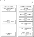
- FIG. 1 is a block diagram illustrating a configuration of a connection detection system 10 according to an embodiment of the disclosure.
- connection detection system 10 may include a first device 100 and a second device 200 for detecting whether the first device 100 is attached thereto.
- the first device 100 may be a slave device such as a robot
- the second device 200 may be a master device to which the slave device is attached, but the disclosure is not limited thereto and may be widely applied to various applications in which one device is attached to another device.
- the first device 100 may include a first connection terminal 110 including a 1-1 contact point 111 and a 1-2 contact point 112 and a first reactance element 120 connected to the first connection terminal 110.
- the second device 200 may include a second connection terminal 210 including a 2-1 contact point 211 and a 2-2 contact point 212 corresponding to the 1-1 contact point 111 and the 1-2 contact point 112, a first resistance element 220, a first frequency generator 230 configured to apply a signal having a frequency varying in a predetermined range to the first device 100 through the second connection terminal 210 via the first resistance element 220, a first comparator 240 having both input terminals connected to both ends of the first resistance element 220 and configured to compare the signals of both ends of the first resistance element 220 to generate output signal, and a first controller 250 configured to determine whether the first connection terminal 110 of the first device 100 is connected to the second connection terminal 210 by using the output signal of the first comparator 240.
- the first connection terminal 110 may include a 1-3 contact point 113
- the second connection terminal 210 may include a 2-3 contact point 213 corresponding to the 1-3 contact point 113. Accordingly, the first controller 250 may detect the connection between the first connection terminal 110 and the second connection terminal 210 and then perform control to apply power to the first device 100 through the 2-3 contact point 213.
- the second device 200 may accurately detect whether the first device 100 is connected thereto and stably supply power and signals required for the operation of the first device 100, and the second device 200 may identify the connected first device 100 and allow the connection only for the first device 100 allowed to be connected.
- FIG. 3 is a flowchart illustrating a connection detection method according to an embodiment of the disclosure.
- the connection detection method by which the second device 200 detects whether there is a connection with the first device 100 including the first connection terminal 110 having the 1-1 contact point 111 and the 1-2 contact point 112 and the first reactance element 120 connected to the first connection terminal 110 may include a signal application operation S110 in which the second device 200 generates a signal having a frequency varying in a predetermined range and applies the signal to the first device 100 through the second connection terminal 210 having the 2-1 contact point 211 and the 2-2 contact point 212 corresponding to the 1-1 contact point 111 and the 1-2 contact point 112 via the first resistance element 220.
- the second device 200 compares signals at both ends of the first resistance element 220, and in a connection determination operation S130, the second device 200 determines whether the first connection terminal 110 of the first device 100 is connected to the second connection terminal 210 by using a result of the comparison between the signals at both ends of the first resistance element 220.
- the second device 200 may generate a signal having a frequency varying in a predetermined range and apply the signal to the first device 200 through the second connection terminal 210 including the 2-1 contact point 211 and the 2-2 contact point 212 corresponding to the 1-1 contact point 111 and the 1-2 contact point 112 via the first resistance element 220.
- the first frequency generator 230 of the second device 200 may generate a signal while changing the frequency in a predetermined range and output the signal to the first resistance element 220.
- the signal passing through the first resistance element 220 may be applied to the first reactance element 120 via the 2-1 contact point 211 and the 1-1 contact point 111 and transmitted back to the first frequency generator 230 via the 1-2 contact point 112 and the 2-2 contact point 212, which configures a circuit.
- the first reactance element 120 may be configured as a capacitor but the disclosure is not necessarily limited thereto, and may be configured as an inductor, configured to include both the capacitor and the inductor, or configured to include a resistance element.
- the case in which the first reactance element 120 is configured as a capacitor is described as an example.
- the frequency of a signal having the size attenuated by 3 dB or having a phase delayed by 45 degrees according to the increase in the frequency is referred to as a cut-off frequency (fc), and the cut-off frequency is determined according to an RC time constant of the circuit, and thus, if the cut-off frequency for the circuit is measured in a condition in which a resistance value of the first resistance element 220 is determined, the capacitance value of the first reactance element 120 may be calculated.
- the first frequency generator 230 may generate and output the signal while changing the frequency
- the first comparator 240 may measure the attenuation of the amplitude of the signal or the phase delay by the first resistance element 220 according to the frequency change of the signal
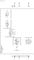
- the cut-off frequency can be more rapidly measured through measurement of the cut-off frequency by the first frequency generator 230 applying signals while changing the frequency in a limited range on the basis of a predicted value of the cut-off frequency according to the first reactance element 120 ( FIG. 5B ).
- the predicted value of the cut-off frequency or the limited range on the basis thereof ( FIG. 5B ) may be preconfigured by a user.
- the limited range may include a plurality of frequency ranges.
- the manager may configure the limited range to include all of a frequency range (ex. 37 to 57 uF) based on a first reactance element value (ex. 47 uF) of the camera device and a frequency range (ex. 1 to 20 uF) based on a first reactance element value (ex. 10 uF) of the display device.
- the second device 200 compares signals at both ends of the first resistance element 220.
- the second device 200 may include the first comparator 240, and both input terminals of the first comparator 240 are connected to both ends of the first resistance element 220 and thus may compare the the signals of the first resistance element 220 to generate output signal.
- FIGS. 6A and 6B illustrate a detailed configuration of the first comparator 240 according to an embodiment of the disclosure.
- the first comparator 240 may include a 1-1 comparator 241 configured to compare an original signal 310 generated by the first frequency generator 230 and applied to the first resistance element 220 and a preset reference signal 340 (VREF) and a 1-2 comparator 242 configured to compare a phase delay signal 320 having passed through the first resistance element 220 and the reference signal 340 (VREF) (first implementation example).
- a 1-1 comparator 241 configured to compare an original signal 310 generated by the first frequency generator 230 and applied to the first resistance element 220 and a preset reference signal 340 (VREF)
- a 1-2 comparator 242 configured to compare a phase delay signal 320 having passed through the first resistance element 220 and the reference signal 340 (VREF) (first implementation example).
- the reference signal 340 may be input into the second comparator 240, and the reference signal 340 may be determined as an intermediate value between the voltage upper limit and the voltage lower limit of the original signal 310 and the phase delay signal 320, but the disclosure is not necessarily limited thereto.
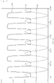
- FIG. 7 illustrates a waveform in the first implementation example. More specifically, as illustrated in FIG. 7 , the 1-1 comparator 241 may compare the original signal 310 and the reference signal 340 and measure first timing (T1 of FIG. 7 ) at which the original signal 310 and the reference signal 340 cross, and the 1-2 comparator 242 may compare the phase delay signal 320 and the reference signal 340 and measure second timing (T2 of FIG. 7 ) at which the phase delay signal 320 and the reference signal 340 cross.
- the first controller 250 may detect a phase difference between the original signal 310 and the phase delay signal 320 on the basis of a difference between the first timing (T1) and the second timing (T2) and a cut-off frequency (fc) corresponding thereto, and thus may calculate an element value of the first reactance element 120.
- the first comparator 240 may include a 1-3 comparator 243 configured to compare the original signal 310 generated by the first frequency generator 230 and applied to the first resistance element 220 and the phase delay signal 320 having passed through the first resistance element 220 (second implementation example).
- the 1-3 comparator 243 may compare the original signal 310 and the phase delay signal 320 and output a phase comparison signal 330, and the first controller 250 may calculate a phase delay of the phase delay signal 320 on the basis of the phase comparison signal 330.
- FIGS. 8A to 8D illustrate the original signal 310 generated by the first frequency generator 230 and applied to the first resistance element 220, the phase delay signal 320 having passed through the first resistance element 220, and the phase comparison signal 330 output after the original signal 310 and the phase delay signal 320 are input into the first comparator 240.
- the phase comparison signal 330 has a high or low signal waveform based on a time point at which phases of the original signal 310 and the phase delay signal 320 cross.
- Timing (phase) at which the phase comparison signal 330 varies and the phase difference between the original signal 310 and the phase delay signal 320 have one-to-one correspondence may be pre-stored in the form of an equation or a lookup table.
- the first controller 250 may acquire the phase difference between the original signal 310 and the phase delay signal 320 corresponding to timing at which the comparator output varies on the basis of the pre-stored one-to-one correspondence relationship between two variables.
- the first controller 250 may measure a phase delay amount of the phase delay signal 320 according to a frequency increase based on the phase comparison signal 330 output from the first comparator 240 and detect a cut-off frequency (fc) and, accordingly, calculate the element value of the first reactance element 120.
- fc cut-off frequency
- FIGS. 8A to 8D illustrate the case in which the cut-off frequency (fc) of the circuit is detected on the basis of the phase delay between the original signal 310, and the phase delay signal 320 and the element value of the first reactance element 120 is calculated using the same.
- the disclosure is not necessarily limited this, and the first comparator 240 may compare sizes of the signals at both ends of the first resistance element 220 and measure an attenuation level according to a frequency increase, and the first controller 250 may detect the cut-off frequency (fc) of the circuit on the basis thereof and calculate the element value of the first reaction element 120.
- the disclosure is not necessarily limited thereto, and the first comparator 240 can be variously configured to detect the phase difference between the original signal 310 and the phase delay signal 320.
- the second device 200 determines whether the first connection terminal 110 of the first device 100 is connected to the second connection terminal 210 on the basis of the result of the signal comparison between both ends of the first resistance element 220.
- the first controller 250 may identify the first device 100 on the basis of the calculated element value of the first reactance element 120 and determine whether the first device 100 is a device allowed to be attached, so as to determine whether to allow the connection.
- the first connection terminal 110 may include the 1-3 contact point 113 and the second connection terminal 210 may include the 2-3 contact point 213 corresponding to the 1-3 contact point 113, in which case the first controller 250 may detect the connection between the first connection terminal 110 and the second connection terminal 210 and then perform control to apply power to the first device 100 through the 2-3 contact point 213.
- the first controller 250 may determine that a camera module device is attached, supply first power for driving the camera device, and transmit a signal for controlling the camera device.
- the first controller 250 may determine that a display module device is attached, supply second power for driving the display module device, and transmit a signal for controlling the display module device.
- the first controller 250 may determine that an unknown device is attached and block power without supplying the power to the device.
- the first device 100 may include a third connection terminal 190 including a 3-1 contact point 191 and a 3-2 contact point 192, a second resistance element 140, a second frequency generator 150 configured to apply a signal having a frequency varying in a predetermined range to a third device (not shown) through the third connection terminal 190 via the second resistance element 140, a second comparator 160 having both input terminals connected to both ends of the second resistance element 140 and configured to compare the signals of both ends of the second resistance element 140 to generate output signal, and a second controller 170 configured to determine whether a fourth connection terminal (not shown) of the third device is connected to the third connection terminal 190 on the basis of the output signal of the second comparator 160, as illustrated in FIG. 9 .
- the third connection terminal 190 may include a 3-3 contact point 193 and the fourth connection terminal (not shown) may include a 4-3 contact point (not shown) corresponding to the 3-3 contact point 193, and accordingly, the second controller 170 may detect the connection between the third connection terminal 190 and the fourth connection terminal and then perform control to apply power to the third device (not shown) through the 3-3 contact point 193. Accordingly, in the system, the apparatus, and the method for detecting the connection according to an embodiment of the disclosure, when the third device (not shown) is attached to the first device 100 attached to the second device 200, the second controller 170 of the first device 100 may detect whether the third device is attached and also determine whether to supply power to the third device and to transmit a control signal or the like.
- the second controller 170 may transmit information on a connection state of the third device to the second device 200 and allow the second device 200 to process power supply and control signal transmission in consideration of both the first device 100 and the third device.
- the structure in which a plurality of devices are sequentially attached can be implemented as the third device detects whether a fourth device (not shown) is attached and processes power supply and control signal transmission to the fourth device.
- FIG. 10 is a detailed flowchart illustrating a connection detection method according to an embodiment of the disclosure.
- the second device 200 first, in operation S210, the second device 200 generates a signal having a frequency varying in a predetermined range through the first frequency generator 230 and output the signal to the first resistance element 220.
- the signal generated by the first frequency generator 230 configures a circuit passing through the first resistance element 220 and the first reactance element 120 such as a capacitor included in the first device 100.
- the first comparator 240 of the second device 200 compares the signal generated by the first frequency generator 230 and a phase delay of a signal by the first reactance element 120 such as the capacitor.
- the first controller 250 of the second device 200 measures a phase delay according to a change in a frequency of the signal, calculates a capacitance value of the first reactance element 120, and then determines whether the first device 100 such as a slave device is attached on the basis of the calculated capacitance value of the first reactance element 120.
- the first controller 250 applies power to the first device 100 to drive the first device 100 when the calculated capacitance value is appropriate and it is determined that the first device 100 is attached, and blocks power to the first device 100 when the calculated capacitance value is inappropriate and it is determined that the first device 100 is not attached.
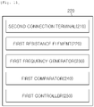
- FIG. 11 is block diagram illustrating the connection detection device 200 according to an embodiment of the disclosure.
- connection detection device 200 may include the second connection terminal 210, the first resistance element 220, the first frequency generator 230, the first comparator 240, and the first controller 250.
- connection detection device 200 according to an embodiment of the disclosure is separately described for each element. Further, a detailed description of the connection detection device 200 according to an embodiment of the disclosure can be implemented by various embodiments similar to the connection detection system 10 and method according to an embodiment of the disclosure in FIGS. 1 to 10 described above, and thus a duplicated description is omitted.
- connection detection device 200 is configured to detect whether there is a connection with the first device 100, which includes the first connection terminal 110 including the 1-1 contact point 111 and the 1-2 contact point 112 and the first reactance element 120 connected to the first connection terminal 110, and includes the second connection terminal 210 including the 2-1 contact point 211 and the 2-2 contact point 212 corresponding to the 1-1 contact point 111 and the 1-2 contact point 112 and the first resistance element 220.
- the first frequency generator 230 applies a signal having a frequency varying in a predetermined range to the first device 100 through the second connection terminal 210 via the first resistance element 220.
- the first comparator 240 has both input terminals connected to both ends of the first resistance element 220 and compares and outputs signals at both ends of the first resistance element 220.
- the first controller 250 determines whether the first connection terminal 110 of the first device 100 is connected to the second connection terminal 210 on the basis of the output signal of the first comparator 240.
- the first connection terminal 110 may include the 1-3 contact point 113 and the second connection terminal 210 may include the 2-3 contact point 213 corresponding to the 1-3 contact point 113, and accordingly, the first controller 250 may detect the connection between the first connection terminal 110 and the second connection terminal 210 and then perform control to apply power to the first device 100 through the 2-3 contact point 213.
- the second device 200 may accurately detect whether the first device 100 is connected thereto and stably supply power and signals required for the operation of the first device 100, and the second device 200 may identify the connected first device 100 and allow the connection only for the first device 100 allowed to be connected.
Landscapes
- Engineering & Computer Science (AREA)
- Physics & Mathematics (AREA)
- General Physics & Mathematics (AREA)
- Theoretical Computer Science (AREA)
- General Engineering & Computer Science (AREA)
- Nonlinear Science (AREA)
- Robotics (AREA)
- Mechanical Engineering (AREA)
- Computer Hardware Design (AREA)
- Human Computer Interaction (AREA)
- Measurement Of Resistance Or Impedance (AREA)
- Testing Of Short-Circuits, Discontinuities, Leakage, Or Incorrect Line Connections (AREA)
Abstract
Description
- The disclosure relates to a system, an apparatus, and a method for detecting a connection for a connecting structure and, more particularly, to a system, an apparatus, and a method for detecting a connection for a connecting structure capable of, when a first device is connected to a second device, automatically detecting the connection and identify the first device.
- Recently, applications for applying robot technologies such as logics/production automation have rapidly expanded. In connection with this, examples of applying a connection structure for attaching a slave device having various functions to a master device such as a robot body to link the slave device with the master device have increased.
- Further, the connecting structure is not limited to a robot field but is widely used for various devices. However, in the conventional connecting structure, when the master device always supplies power and signals without recognizing whether the slave device is connected, noise or sparks are generated at a connection terminal due to the connection if the slave device is attached in the state in which power and signals are supplied to the connection terminal, and the connection terminal is shorted and a power supply circuit of the master device is damaged if a foreign material having conductivity comes into contact with the connection terminal.
- A method is also known in which, when the slave device has in advance a predetermined size of resistance and the slave device is connected to the master device, a connection terminal measures the resistance of the slave device and the master device detects whether the slave device is connected. Even in this case, if a foreign material having a resistance value similar to the resistance of the slave device comes into contact with the connection terminal, a problem may occur in that it is determined erroneously as if the slave device were connected when it is not.
- Therefore, there is a need for a method by which the master device is able to accurately detect whether the slave device is attached and safely supply power and signals required for the operation of the slave device.
- The disclosure has been made to solve the problem of the conventional art, and an aspect of the disclosure is to allow a master device to accurately detect whether a slave device is attached and safely supply power and signals required for the operation of the slave device.
- Another aspect of the disclosure is to allow the master device to identify the slave device and permit the connection for only the slave device allowed to be attached.
- Other detailed aspects of the disclosure may be clearly detected and understood by those skilled in the art through the following detailed description.
- In accordance with an aspect of the disclosure, a system for detecting a connection includes: a first device including a first connection terminal having a 1-1 contact point and a 1-2 contact point, and a first reactance element connected to the first connection terminal; and a second device including a second connection terminal having a 2-1 contact point and a 2-2 contact point corresponding to the 1-1 contact point and the 1-2 contact point, a first resistance element, a first frequency generator configured to apply a signal having a frequency varying a predetermined range to the first device through the second connection terminal via the first resistance element, a first comparator having both input terminals connected to both ends of the first resistance element and configured to compare the signals of both ends of the first resistance element to generate output signal, and a first controller configured to determine whether the first connection terminal is connected to the second connection terminal by using an output signal of the first comparator.
- In accordance with another aspect of the disclosure, an apparatus for detecting a connection detects whether there is a connection with a first device, the first device including a first connection terminal having a 1-1 contact point and a 1-2 contact point, and a first reactance element connected to the first connection terminal. The apparatus includes a second connection terminal having a 2-1 contact point and a 2-2 contact point corresponding to the 1-1 contact point and the 1-2 contact point, a first resistance element, a first frequency generator configured to apply a signal having a frequency varying in a predetermined range to the first device through the second connection terminal via the first resistance element, a first comparator having both input ends connected to both ends of the first resistance element and configured to compare the signals of both ends of the first resistance element to generate output signal, and a first controller configured to determine whether the first connection terminal of the first device is connected to the second connection terminal by using an output signal of the first comparator.
- In accordance with another aspect of the disclosure, a method of detecting a connection detects whether there is a connection with a first device, the first device including a first connection terminal having a 1-1 contact point and a 1-2 contact point and a first reactance element connected to the first connection terminal. The method includes: a signal application step of generating a signal having a frequency varying in a predetermined range and applying the signal to the first device through a second connection terminal having a 2-1 contact point and a 2-2 contact point corresponding to the 1-1 contact point and the 1-2 contact point via a first resistance element by the second device; a signal comparison step of comparing signals at both ends of the first resistance element by the second device; and a connection determination step of determining whether the first connection terminal of the first device is connected to the second connection terminal by using a result of the comparison between the signals at both ends of the first resistance element by the second device.
- Accordingly, in the system, the apparatus, and the method for detecting a connection according to an embodiment of the disclosure, when the first device is attached to the second device, the second device accurately detect whether the first device is attached and can safely supply power and signals required for the operation of the first device.
- Further, in the system, the apparatus, and the method for detecting the connection according to an embodiment of the disclosure, the second device identifies the attached first device and can perform the connection for only the first device allowed to be attached.
- The accompanying drawings included as a part of the detailed description to help understanding of the disclosure, provide embodiments and the technical idea of the disclosure along with the detailed description.
-
FIG. 1 is a block diagram illustrating a connection detection system according to an embodiment of the disclosure. -
FIG. 2 is a schematic diagram of the connection detection system according to an embodiment of the disclosure. -
FIG. 3 is a flowchart of a connection detection method according to an embodiment of the disclosure. -
FIGS. 4 and5 illustrate a detailed operation in which the connection detection system, device, and method according to an embodiment of the disclosure detect the connection of a first device. -
FIGS. 6A and 6B are schematic diagrams of a first comparator in the connection detection system according to an embodiment of the disclosure. -
FIG. 7 illustrates a waveform in a first implementation example of the first comparator in the connection detection system according to an embodiment of the disclosure. -
FIGS. 8A to 8D illustrate a waveform in a second implementation example of the first comparator in the connection detection system according to an embodiment of the disclosure. -
FIG. 9 is a schematic diagram of another embodiment of the first device in the connection detection system. -
FIG. 10 is a detailed flowchart illustrating the connection detection method according to an embodiment of the disclosure. -
FIG. 11 is a block diagram illustrating the connection detection device according to an embodiment of the disclosure. - The disclosure may have various modifications and various embodiments, and hereinafter, specific embodiments based on the accompanying drawings are described in detail.
- The following embodiments are provided to help comprehensive understanding of a method, an apparatus, and/or a system described in the specification. However, this is only an example and the disclosure is not limited thereto.
- In a description of embodiments of the disclosure, if it is determined that a detailed description of known technology related to the disclosure makes the subject of the disclosure unclear, the detailed description is omitted. The definitions of the terms should be made based on the contents throughout the specification. Terms used in the detailed description are to merely describe embodiments of the disclosure and should not be restrictive. The expression of a singular form includes meaning of a plural form unless the context clearly dictates otherwise. In the description, it should be understood that the expression such as "include" or "have" indicates characteristics, numbers, steps, operations, elements, parts, or combinations thereof but does not exclude the presence or possibility of one or more other characteristics, numbers, steps, operations, elements, parts, or combinations thereof.
- Further, the terms first, second, and the like may be used to describe various elements, but the elements are not limited by the terms and are used to only distinguish one element from another element.
- Hereinafter, embodiments of a system, an apparatus, and a method for detecting a connection according to an embodiment of the disclosure are sequentially described with reference to the accompanying drawings.
- First,
FIG. 1 is a block diagram illustrating a configuration of aconnection detection system 10 according to an embodiment of the disclosure. - As illustrated in
FIG. 1 , theconnection detection system 10 according to an embodiment of the disclosure may include afirst device 100 and asecond device 200 for detecting whether thefirst device 100 is attached thereto. - At this time, the
first device 100 may be a slave device such as a robot, and thesecond device 200 may be a master device to which the slave device is attached, but the disclosure is not limited thereto and may be widely applied to various applications in which one device is attached to another device. - More specifically, as illustrated in
FIG. 2 , thefirst device 100 may include afirst connection terminal 110 including a 1-1contact point 111 and a 1-2contact point 112 and afirst reactance element 120 connected to thefirst connection terminal 110. - Further, the
second device 200 may include asecond connection terminal 210 including a 2-1contact point 211 and a 2-2contact point 212 corresponding to the 1-1contact point 111 and the 1-2contact point 112, afirst resistance element 220, afirst frequency generator 230 configured to apply a signal having a frequency varying in a predetermined range to thefirst device 100 through thesecond connection terminal 210 via thefirst resistance element 220, afirst comparator 240 having both input terminals connected to both ends of thefirst resistance element 220 and configured to compare the signals of both ends of thefirst resistance element 220 to generate output signal, and afirst controller 250 configured to determine whether thefirst connection terminal 110 of thefirst device 100 is connected to thesecond connection terminal 210 by using the output signal of thefirst comparator 240. - The
first comparator 240 may be a phase comparator configured to compare phases of the signals at both ends of thefirst resistance element 220. Accordingly, thefirst controller 250 may measure a first frequency (=fC1) of a phase delay between the signals at both ends of thefirst resistance element 220 by using the output signal of the phase comparator, the phase delay being out of a predetermined range according to an increase in the frequency of thefirst frequency generator 230. The first controller then determines whether thefirst connection terminal 110 of thefirst device 100 is connected to thesecond connection terminal 210 on the basis of the first frequency (=fC1) or an element value of thefirst reactance element 120 calculated using the first frequency (=fC1). - Further, the
first controller 250 may measure a second frequency (=fC2) of an amplitude change between the signals at both ends of thefirst resistance element 220, the size change being output a predetermined range according to an increase in the frequency of thefirst frequency generator 230, and then verify whether the first frequency (=fC1) is accurate by using the second frequency (=fC2). - The
first connection terminal 110 may include a 1-3contact point 113, and thesecond connection terminal 210 may include a 2-3contact point 213 corresponding to the 1-3contact point 113. Accordingly, thefirst controller 250 may detect the connection between thefirst connection terminal 110 and thesecond connection terminal 210 and then perform control to apply power to thefirst device 100 through the 2-3contact point 213. - Further, the
first frequency generator 230 can apply a signal while changing a frequency in a limited range on the basis of a predicted value of the first frequency (=fC1) according to thefirst reactance element 120. - Accordingly, when the
first device 100 is attached to thesecond device 200, thesecond device 200 may accurately detect whether thefirst device 100 is connected thereto and stably supply power and signals required for the operation of thefirst device 100, and thesecond device 200 may identify the connectedfirst device 100 and allow the connection only for thefirst device 100 allowed to be connected. -
FIG. 3 is a flowchart illustrating a connection detection method according to an embodiment of the disclosure. - As illustrated in
FIG. 3 , the connection detection method by which thesecond device 200 detects whether there is a connection with thefirst device 100 including thefirst connection terminal 110 having the 1-1contact point 111 and the 1-2contact point 112 and thefirst reactance element 120 connected to thefirst connection terminal 110 according to an embodiment of the disclosure may include a signal application operation S110 in which thesecond device 200 generates a signal having a frequency varying in a predetermined range and applies the signal to thefirst device 100 through thesecond connection terminal 210 having the 2-1contact point 211 and the 2-2contact point 212 corresponding to the 1-1contact point 111 and the 1-2contact point 112 via thefirst resistance element 220. In a signal comparison operation S120 , thesecond device 200 compares signals at both ends of thefirst resistance element 220, and in a connection determination operation S130, thesecond device 200 determines whether thefirst connection terminal 110 of thefirst device 100 is connected to thesecond connection terminal 210 by using a result of the comparison between the signals at both ends of thefirst resistance element 220. - Hereinafter, the system, the apparatus, and the method for detecting the connection according to an embodiment of the disclosure are described in more detail for each element with reference toFIGS. 1 to 3.
- First, in the signal application operation S110, the
second device 200 may generate a signal having a frequency varying in a predetermined range and apply the signal to thefirst device 200 through thesecond connection terminal 210 including the 2-1contact point 211 and the 2-2contact point 212 corresponding to the 1-1contact point 111 and the 1-2contact point 112 via the first resistance element 220.More specifically, as illustrated inFIG. 2 , thefirst frequency generator 230 of thesecond device 200 may generate a signal while changing the frequency in a predetermined range and output the signal to thefirst resistance element 220. The signal passing through thefirst resistance element 220 may be applied to thefirst reactance element 120 via the 2-1contact point 211 and the 1-1contact point 111 and transmitted back to thefirst frequency generator 230 via the 1-2contact point 112 and the 2-2contact point 212, which configures a circuit. - As illustrated in
FIG. 2 , thefirst reactance element 120 may be configured as a capacitor but the disclosure is not necessarily limited thereto, and may be configured as an inductor, configured to include both the capacitor and the inductor, or configured to include a resistance element. Hereinafter, the case in which thefirst reactance element 120 is configured as a capacitor is described as an example. - Accordingly, as illustrated in
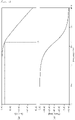
FIGS. 4(a) and 4(b) , when the frequency of the signal generated by thefirst frequency generator 230 increases, the size of the signal is attenuated while passing through thefirst resistance element 220 according to the frequency response characteristic of an RC circuit and a phase is delayed. - More specifically, the frequency of a signal having the size attenuated by 3 dB or having a phase delayed by 45 degrees according to the increase in the frequency is referred to as a cut-off frequency (fc), and the cut-off frequency is determined according to an RC time constant of the circuit, and thus, if the cut-off frequency for the circuit is measured in a condition in which a resistance value of the
first resistance element 220 is determined, the capacitance value of thefirst reactance element 120 may be calculated. - Accordingly, in an example of the disclosure, when the
first frequency generator 230 generates and outputs the signal while changing the frequency, thefirst comparator 240 may measure the attenuation of the amplitude of the signal or the phase delay by thefirst resistance element 220 according to the frequency change of the signal, and thefirst controller 250 may calculate the capacitance value of thefirst reactance element 120 by using the first frequency (=fc1) and/or the second frequency (=fc2) and then determine whether thefirst device 100 is attached to thesecond device 200 on the basis of the calculated capacitance value of thefirst reactance element 120. Further, it is possible to determine whether the connection is allowed by identifying the type of the attachedfirst device 100. - According to another example, the
first frequency generator 230 may generate and output the signal while changing the frequency, thefirst comparator 240 may measure the attenuation of the amplitude of the signal or the phase delay by thefirst resistance element 220 according to the frequency change of the signal, and thefirst controller 250 may determine whether thefirst device 100 is attached to thesecond device 200 on the basis of the first frequency (=fc1) and/or the second frequency (=fc2). In addition, it is possible to determine whether the connection is allowed by identifying the type of the attachedfirst device 100. - As illustrated in
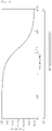
FIG. 5 , it is possible to measure the cut-off frequency by applying signals in the entire range of frequencies which can be generated by the first frequency generator 230 (A), but the cut-off frequency can be more rapidly measured through measurement of the cut-off frequency by thefirst frequency generator 230 applying signals while changing the frequency in a limited range on the basis of a predicted value of the cut-off frequency according to the first reactance element 120 (FIG. 5B ). The predicted value of the cut-off frequency or the limited range on the basis thereof (FIG. 5B ) may be preconfigured by a user. Further, the limited range may include a plurality of frequency ranges. For example, when a device which can be connected to thesecond device 200 includes a camera device and a display device as thefirst device 100, the manager may configure the limited range to include all of a frequency range (ex. 37 to 57 uF) based on a first reactance element value (ex. 47 uF) of the camera device and a frequency range (ex. 1 to 20 uF) based on a first reactance element value (ex. 10 uF) of the display device. - Subsequently, in the signal comparison operation S120, the
second device 200 compares signals at both ends of thefirst resistance element 220. - More specifically, as illustrated in
FIG. 2 , thesecond device 200 may include thefirst comparator 240, and both input terminals of thefirst comparator 240 are connected to both ends of thefirst resistance element 220 and thus may compare the the signals of thefirst resistance element 220 to generate output signal. - The
first comparator 250 may be a phase comparator configured to compare phases of signals at both ends of thefirst resistance element 220. Accordingly, thefirst controller 250 may measure a first frequency (=fC1) (for example, a frequency having a phase delay of 45 degrees or more) of a phase delay between signals at both ends of thefirst resistance element 220, the phase delay being out of a predetermined range according to an increase in the frequency of thefirst frequency generator 230, calculate an element value of thefirst reactance element 120 by using the first frequency (=fC1), and determine whether thefirst connection terminal 110 of thefirst device 100 is connected to thesecond connection terminal 210. - In a more detailed example,
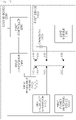
FIGS. 6A and 6B illustrate a detailed configuration of thefirst comparator 240 according to an embodiment of the disclosure. - First, as illustrated in
FIG. 6A , thefirst comparator 240 may include a 1-1comparator 241 configured to compare anoriginal signal 310 generated by thefirst frequency generator 230 and applied to thefirst resistance element 220 and a preset reference signal 340 (VREF) and a 1-2comparator 242 configured to compare aphase delay signal 320 having passed through thefirst resistance element 220 and the reference signal 340 (VREF) (first implementation example). - As illustrated in
FIG. 6A , thereference signal 340 may be input into thesecond comparator 240, and thereference signal 340 may be determined as an intermediate value between the voltage upper limit and the voltage lower limit of theoriginal signal 310 and thephase delay signal 320, but the disclosure is not necessarily limited thereto. -
FIG. 7 illustrates a waveform in the first implementation example. More specifically, as illustrated inFIG. 7 , the 1-1comparator 241 may compare theoriginal signal 310 and thereference signal 340 and measure first timing (T1 ofFIG. 7 ) at which theoriginal signal 310 and thereference signal 340 cross, and the 1-2comparator 242 may compare thephase delay signal 320 and thereference signal 340 and measure second timing (T2 ofFIG. 7 ) at which thephase delay signal 320 and thereference signal 340 cross. - Accordingly, the
first controller 250 may detect a phase difference between theoriginal signal 310 and thephase delay signal 320 on the basis of a difference between the first timing (T1) and the second timing (T2) and a cut-off frequency (fc) corresponding thereto, and thus may calculate an element value of thefirst reactance element 120. - Further, as illustrated in
FIG. 6B , thefirst comparator 240 may include a 1-3comparator 243 configured to compare theoriginal signal 310 generated by thefirst frequency generator 230 and applied to thefirst resistance element 220 and thephase delay signal 320 having passed through the first resistance element 220 (second implementation example). - The 1-3
comparator 243 may compare theoriginal signal 310 and thephase delay signal 320 and output aphase comparison signal 330, and thefirst controller 250 may calculate a phase delay of thephase delay signal 320 on the basis of thephase comparison signal 330. - In a more detailed example,
FIGS. 8A to 8D illustrate theoriginal signal 310 generated by thefirst frequency generator 230 and applied to thefirst resistance element 220, thephase delay signal 320 having passed through thefirst resistance element 220, and thephase comparison signal 330 output after theoriginal signal 310 and thephase delay signal 320 are input into thefirst comparator 240. - As illustrated in
FIGS. 8A to 8D , thephase comparison signal 330 has a high or low signal waveform based on a time point at which phases of theoriginal signal 310 and thephase delay signal 320 cross. - Timing (phase) at which the
phase comparison signal 330 varies and the phase difference between theoriginal signal 310 and thephase delay signal 320 have one-to-one correspondence. The one-to-one correspondence relationship between two variables may be pre-stored in the form of an equation or a lookup table. Thefirst controller 250 may acquire the phase difference between theoriginal signal 310 and thephase delay signal 320 corresponding to timing at which the comparator output varies on the basis of the pre-stored one-to-one correspondence relationship between two variables. - Accordingly, the
first controller 250 may measure a phase delay amount of thephase delay signal 320 according to a frequency increase based on thephase comparison signal 330 output from thefirst comparator 240 and detect a cut-off frequency (fc) and, accordingly, calculate the element value of thefirst reactance element 120. - Further,
FIGS. 8A to 8D illustrate the case in which the cut-off frequency (fc) of the circuit is detected on the basis of the phase delay between theoriginal signal 310, and thephase delay signal 320 and the element value of thefirst reactance element 120 is calculated using the same. The disclosure is not necessarily limited this, and thefirst comparator 240 may compare sizes of the signals at both ends of thefirst resistance element 220 and measure an attenuation level according to a frequency increase, and thefirst controller 250 may detect the cut-off frequency (fc) of the circuit on the basis thereof and calculate the element value of thefirst reaction element 120. - In the disclosure, the
first controller 250 may perform a process of detecting a second frequency (=fc2) of a size change between the signals at both ends of thefirst resistance element 220, the size change being out of a predetermined range according to an increase of the frequency of thefirst frequency generator 230, and verifying whether the first frequency (=fc1) is accurate, so as to prevent an error of the cut-off frequency and more accurately calculate the element value of thefirst reactance element 120. - Although the first implementation example (
FIG. 6A ) and the second implementation example (FIG. 6B ) have been described for thefirst comparator 240, the disclosure is not necessarily limited thereto, and thefirst comparator 240 can be variously configured to detect the phase difference between theoriginal signal 310 and thephase delay signal 320. - Accordingly, in the operation S130 of determining whether there is the connection, the
second device 200 determines whether thefirst connection terminal 110 of thefirst device 100 is connected to thesecond connection terminal 210 on the basis of the result of the signal comparison between both ends of thefirst resistance element 220. - More specifically, after detecting the first frequency (=fc1) of the phase delay between the signals at both ends of the
first resistance element 220, the phase delay being out of the predetermined range, thefirst controller 250 may calculate the element value of thefirst reactance element 120 by using the first frequency (=fc1) and determine whether thefirst connection terminal 110 of thefirst device 100 is connected to thesecond connection terminal 210. - The
first controller 250 may identify thefirst device 100 on the basis of the calculated element value of thefirst reactance element 120 and determine whether thefirst device 100 is a device allowed to be attached, so as to determine whether to allow the connection. - In the disclosure, the
first connection terminal 110 may include the 1-3contact point 113 and thesecond connection terminal 210 may include the 2-3contact point 213 corresponding to the 1-3contact point 113, in which case thefirst controller 250 may detect the connection between thefirst connection terminal 110 and thesecond connection terminal 210 and then perform control to apply power to thefirst device 100 through the 2-3contact point 213. - In a more detailed example, when the element value of the
first reactance element 120 is 47 uF, thefirst controller 250 may determine that a camera module device is attached, supply first power for driving the camera device, and transmit a signal for controlling the camera device. - Alternatively, when the element value of the
first reactance element 120 is 10 uF, thefirst controller 250 may determine that a display module device is attached, supply second power for driving the display module device, and transmit a signal for controlling the display module device. - On the other hand, when the element value of the
first reactance element 120 is 100 nF, thefirst controller 250 may determine that an unknown device is attached and block power without supplying the power to the device. - Further, in the system, the apparatus, and the method for detecting the connection according to an embodiment of the disclosure, the
first device 100 may include athird connection terminal 190 including a 3-1contact point 191 and a 3-2contact point 192, asecond resistance element 140, asecond frequency generator 150 configured to apply a signal having a frequency varying in a predetermined range to a third device (not shown) through thethird connection terminal 190 via thesecond resistance element 140, asecond comparator 160 having both input terminals connected to both ends of thesecond resistance element 140 and configured to compare the signals of both ends of thesecond resistance element 140 to generate output signal, and asecond controller 170 configured to determine whether a fourth connection terminal (not shown) of the third device is connected to thethird connection terminal 190 on the basis of the output signal of thesecond comparator 160, as illustrated inFIG. 9 . - The
third connection terminal 190 may include a 3-3contact point 193 and the fourth connection terminal (not shown) may include a 4-3 contact point (not shown) corresponding to the 3-3contact point 193, and accordingly, thesecond controller 170 may detect the connection between thethird connection terminal 190 and the fourth connection terminal and then perform control to apply power to the third device (not shown) through the 3-3contact point 193. Accordingly, in the system, the apparatus, and the method for detecting the connection according to an embodiment of the disclosure, when the third device (not shown) is attached to thefirst device 100 attached to thesecond device 200, thesecond controller 170 of thefirst device 100 may detect whether the third device is attached and also determine whether to supply power to the third device and to transmit a control signal or the like. - The
second controller 170 may transmit information on a connection state of the third device to thesecond device 200 and allow thesecond device 200 to process power supply and control signal transmission in consideration of both thefirst device 100 and the third device. - In addition, in the system, the apparatus, and the method for detecting the connection according to an embodiment of the disclosure, the structure in which a plurality of devices are sequentially attached can be implemented as the third device detects whether a fourth device (not shown) is attached and processes power supply and control signal transmission to the fourth device.
-
FIG. 10 is a detailed flowchart illustrating a connection detection method according to an embodiment of the disclosure. - As illustrated in
FIG. 10 , first, in operation S210, thesecond device 200 generates a signal having a frequency varying in a predetermined range through thefirst frequency generator 230 and output the signal to thefirst resistance element 220. - At this time, the signal generated by the
first frequency generator 230 configures a circuit passing through thefirst resistance element 220 and thefirst reactance element 120 such as a capacitor included in thefirst device 100. - Subsequently, in operation S220, the
first comparator 240 of thesecond device 200 compares the signal generated by thefirst frequency generator 230 and a phase delay of a signal by thefirst reactance element 120 such as the capacitor. - Accordingly, in operation S230, the
first controller 250 of thesecond device 200 measures a phase delay according to a change in a frequency of the signal, calculates a capacitance value of thefirst reactance element 120, and then determines whether thefirst device 100 such as a slave device is attached on the basis of the calculated capacitance value of thefirst reactance element 120. - At this time, the
first controller 250 applies power to thefirst device 100 to drive thefirst device 100 when the calculated capacitance value is appropriate and it is determined that thefirst device 100 is attached, and blocks power to thefirst device 100 when the calculated capacitance value is inappropriate and it is determined that thefirst device 100 is not attached. -
FIG. 11 is block diagram illustrating theconnection detection device 200 according to an embodiment of the disclosure. - As illustrated in
FIG. 11 , theconnection detection device 200 according to an embodiment of the disclosure may include thesecond connection terminal 210, thefirst resistance element 220, thefirst frequency generator 230, thefirst comparator 240, and thefirst controller 250. - Hereinafter, the
connection detection device 200 according to an embodiment of the disclosure is separately described for each element. Further, a detailed description of theconnection detection device 200 according to an embodiment of the disclosure can be implemented by various embodiments similar to theconnection detection system 10 and method according to an embodiment of the disclosure inFIGS. 1 to 10 described above, and thus a duplicated description is omitted. - First, the
connection detection device 200 is configured to detect whether there is a connection with thefirst device 100, which includes thefirst connection terminal 110 including the 1-1contact point 111 and the 1-2contact point 112 and thefirst reactance element 120 connected to thefirst connection terminal 110, and includes thesecond connection terminal 210 including the 2-1contact point 211 and the 2-2contact point 212 corresponding to the 1-1contact point 111 and the 1-2contact point 112 and thefirst resistance element 220. - The
first frequency generator 230 applies a signal having a frequency varying in a predetermined range to thefirst device 100 through thesecond connection terminal 210 via thefirst resistance element 220. - The
first comparator 240 has both input terminals connected to both ends of thefirst resistance element 220 and compares and outputs signals at both ends of thefirst resistance element 220. - The
first controller 250 determines whether thefirst connection terminal 110 of thefirst device 100 is connected to thesecond connection terminal 210 on the basis of the output signal of thefirst comparator 240. - The
first comparator 240 may be a phase comparator configured to compare phases of the signals at both ends of thefirst resistance element 220 in which case thefirst controller 250 may detect a first frequency (=fc1) of a phase delay between the signals at both ends of thefirst resistance element 220 by using the output signal of the phase comparator, the phase delay being out of a predetermined range according to an increase in the frequency of thefirst frequency generator 230, calculate an element value of thefirst reactance element 120 by using the first frequency (=fc1), and determine whether thefirst connection terminal 110 of thefirst device 100 is connected to thesecond connection terminal 210. - The
first controller 250 may detect a second frequency (=fc2) of a size change between the signals at both ends of thefirst resistance element 220, the size change being output of a predetermined range according to an increase in the frequency of thefirst frequency generator 230, and verify whether the first frequency (=fc1) is accurate by using the second frequency (=fc2). - The
first connection terminal 110 may include the 1-3contact point 113 and thesecond connection terminal 210 may include the 2-3contact point 213 corresponding to the 1-3contact point 113, and accordingly, thefirst controller 250 may detect the connection between thefirst connection terminal 110 and thesecond connection terminal 210 and then perform control to apply power to thefirst device 100 through the 2-3contact point 213. - The
first frequency generator 230 may apply the signal while changing the frequency in a limited range on the basis of a predicted value of the first frequency (=fC1) according to thefirst reactance element 120. - Accordingly, in the system, the apparatus, and the method for detecting the connection according to an embodiment of the disclosure, when the
first device 100 is connected to thesecond device 200, thesecond device 200 may accurately detect whether thefirst device 100 is connected thereto and stably supply power and signals required for the operation of thefirst device 100, and thesecond device 200 may identify the connectedfirst device 100 and allow the connection only for thefirst device 100 allowed to be connected. - Although the embodiments of the disclosure have been described for illustrative purposes, those skilled in the art will appreciate that various modifications, additions, and substitutions are possible, without departing from the scope and spirit of the disclosure. Accordingly, embodiments of the disclosure are to describe the technical idea of the disclosure without limiting the same, and the disclosure is not limited to the embodiments. The protection scope of the disclosure should be interpreted by the claims, and all technical ideas within a range equivalent thereto should be construed as being included in the claims of the disclosure.
Claims (9)
- A system for detecting a connection, comprising:a first device including a first connection terminal having a 1-1 contact point and a 1-2 contact point and a first reactance element connected to the first connection terminal; anda second device includinga second connection terminal having a 2-1 contact point and a 2-2 contact point corresponding to the 1-1 contact point and the 1-2 contact point,a first resistance element,a first frequency generator configured to apply a signal having a frequency varying a predetermined range to the first device through the second connection terminal via the first resistance element,a first comparator having both input terminals connected to both ends of the first resistance element and configured to compare the signals of both ends of the first resistance element to generate output signal, and a first controller configured to determine whether the first connection terminal is connected to the second connection terminal by using an output signal of the first comparator.
- The system of claim 1, wherein the first comparator is a phase comparator configured to compare phases of the signals at both ends of the first resistance element, andthe first controller is configured to detect a first frequency (=fC1) of a phase delay between both ends of the first resistance element by using an output signal of the phase comparator, the phase delay being out of a predetermined range according to an increase in the frequency of the first frequency generator, andcalculate an element value of the first reactance element by using the first frequency (=fC1) and determine whether the first connection terminal of the first device is connected to the second connection terminal.
- The system of claim 2, wherein the first controller is configured to detect a second frequency (=fC2) of a size change between the signals at both ends of the first resistance element, the size change being output of a predetermined range according to an increase in the frequency of the first frequency generator, and
verify whether the first frequency (=fC1) is accurate by using the second frequency (=fC2). - The system of claim 1, wherein the first connection terminal comprises a 1-3 contact point,the second connection terminal comprises a 2-3 contact point corresponding to the 1-3 contact point, andthe first controller is configured to detect the connection between the first connection terminal and the second connection and then perform control to apply power to the first device through the 2-3 contact point.
- The system of claim 2, wherein the first frequency generator is configured to apply a signal while changing a frequency within a limited range, based on a predicated value of the first frequency (=fC1) according to the first reactance element.
- The system of claim 1, wherein the first device comprises a third connection terminal having a 3-1 contact point and a 3-2 contact point,a second resistance element,a second frequency generator configured to apply a signal having a frequency varying in a predetermined range to a third device through the third connection terminal via the second resistance element,a second comparator having both input terminals connected to both ends of the second resistance element and configured to compare the signals of both ends of the second resistance element to generate output signal, anda second controller configured to determine whether a fourth connection terminal of the third device is connected to the third connection terminal by using an output signal of the second comparator.
- The system of claim 6, wherein the third connection terminal has a 3-3 contact point,the fourth connection terminal has a 4-3 contact point corresponding to the 3-3 contact point, andthe second controller is configured to detect the connection between the third connection terminal and the fourth connection terminal and then perform control to apply power to the third device through the 3-3 contact point.
- An apparatus for detecting a connection to detect whether there is a connection with a first device having a first connection terminal including a 1-1 contact point and a 1-2 contact point and a first reactance element connected to the first connection terminal, the apparatus comprising:a second connection terminal having a 2-1 contact point and a 2-2 contact point corresponding to the 1-1 contact point and the 1-2 contact point;a first resistance element;a first frequency generator configured to apply a signal having a frequency varying in a predetermined range to the first device through the second connection terminal via the first resistance element;a first comparator having both input ends connected to both ends of the first resistance element and configured to compare the signals of both ends of the first resistance element to generate output signal, anda first controller configured to determine whether the first connection terminal of the first device is connected to the second connection terminal by using an output signal of the first comparator.
- A method of detecting a connection by which a second device detects whether there is a connection with a first device, the first device including a first connection terminal having a 1-1 contact point and a 1-2 contact point and a first reactance element connected to the first connection terminal, the method comprising:a signal application operation in which the second device generates a signal having a frequency varying in a predetermined range and applies the signal to the first device through a second connection terminal having a 2-1 contact point and a 2-2 contact point corresponding to the 1-1 contact point and the 1-2 contact point via a first resistance element;a signal comparison operation in which the second device compares signals at both ends of the first resistance element; anda connection determination operation in which the second device determines whether the first connection terminal of the first device is connected to the second connection terminal by using a result of the comparison between the signals at both ends of the first resistance element.
Applications Claiming Priority (2)
| Application Number | Priority Date | Filing Date | Title |
|---|---|---|---|
| KR1020200013147A KR102249352B1 (en) | 2020-02-04 | 2020-02-04 | Connection sensing system, apparatus and method for connecting structure |
| PCT/KR2020/018785 WO2021157858A1 (en) | 2020-02-04 | 2020-12-21 | System, device and method for detecting connection of connecting structure |
Publications (4)
| Publication Number | Publication Date |
|---|---|
| EP4102240A1 true EP4102240A1 (en) | 2022-12-14 |
| EP4102240A4 EP4102240A4 (en) | 2024-03-06 |
| EP4102240C0 EP4102240C0 (en) | 2025-04-23 |
| EP4102240B1 EP4102240B1 (en) | 2025-04-23 |
Family
ID=75918324
Family Applications (1)
| Application Number | Title | Priority Date | Filing Date |
|---|---|---|---|
| EP20917399.6A Active EP4102240B1 (en) | 2020-02-04 | 2020-12-21 | System, device and method for detecting connection of connecting structure |
Country Status (6)
| Country | Link |
|---|---|
| US (1) | US12000907B2 (en) |
| EP (1) | EP4102240B1 (en) |
| JP (1) | JP7320680B2 (en) |
| KR (1) | KR102249352B1 (en) |
| CN (1) | CN115053142B (en) |
| WO (1) | WO2021157858A1 (en) |
Family Cites Families (21)
| Publication number | Priority date | Publication date | Assignee | Title |
|---|---|---|---|---|
| JP3206724B2 (en) * | 1996-10-23 | 2001-09-10 | 矢崎総業株式会社 | Power supply device and connector connection failure detection method |
| JP4347769B2 (en) | 2004-08-09 | 2009-10-21 | オリンパス株式会社 | Ultrasonic surgical apparatus and abnormality determination method thereof |
| US20070047270A1 (en) | 2005-09-01 | 2007-03-01 | Creative Technology Ltd. | Load detector for an AC-AC power supply |
| FR2923913B1 (en) * | 2007-11-21 | 2014-02-21 | Lohr Ind | ASSEMBLY FOR DETECTING AN ELECTRICAL DISCONNECTION BETWEEN AN ELECTRICAL CONTACT AND AN ELECTRICALLY CONDUCTIVE ELEMENT MOUNTED IN THE DETECTION CIRCUIT |
| US8249501B2 (en) * | 2008-05-05 | 2012-08-21 | International Business Machines Corporation | Self-detecting electronic connection for electronic devices |
| EP2357484B1 (en) * | 2010-01-25 | 2013-03-13 | Siemens Aktiengesellschaft | Method for diagnosing an electrical connection and output assembly |
| JP5729693B2 (en) * | 2011-03-30 | 2015-06-03 | 株式会社ダイヘン | High frequency power supply |
| KR101303215B1 (en) | 2011-06-14 | 2013-09-04 | 고등기술연구원연구조합 | Connection mechanism of a robot hand |
| KR20130034147A (en) * | 2011-09-28 | 2013-04-05 | (주)에스피에스 | Adapter tip for connecting recognition circuit |
| KR101768251B1 (en) | 2013-04-05 | 2017-08-30 | 삼성에스디아이 주식회사 | Battery Pack Providing Confirmation For Normal Connection Of Battery Module |
| KR101302020B1 (en) * | 2013-04-11 | 2013-08-30 | 김상봉 | Testing cable apparatus for multi-articulation robot |
| US20150102824A1 (en) * | 2013-10-11 | 2015-04-16 | General Electric Company | Locating loose connections in an electrical circuit |
| JP6475942B2 (en) * | 2014-09-25 | 2019-02-27 | ルネサスエレクトロニクス株式会社 | Semiconductor device and AC resistance measurement system including the same |
| US9772367B2 (en) * | 2014-11-25 | 2017-09-26 | Dialog Semiconductor Inc. | Load connection detection |
| KR101799569B1 (en) * | 2015-03-10 | 2017-12-20 | 주식회사 엘지화학 | Linkange detection device and method of master BMS between slave BMS |
| JP2017004404A (en) * | 2015-06-15 | 2017-01-05 | ソニー株式会社 | Communication device and control method |
| KR20170122483A (en) * | 2016-04-27 | 2017-11-06 | 엘에스산전 주식회사 | System for detecting communication network |
| CN106226645B (en) * | 2016-07-15 | 2020-06-23 | 联想(北京)有限公司 | Connection detection device and method |
| US10050519B2 (en) * | 2016-12-02 | 2018-08-14 | Vlt, Inc. | Control of buck-boost power converter with input voltage tracking |
| US10746784B2 (en) * | 2017-11-06 | 2020-08-18 | National Instruments Corporation | System level health monitoring in test systems |
| US10352983B1 (en) * | 2018-10-04 | 2019-07-16 | Genmark Diagnostics, Inc. | Systems and methods for assessing electrical connectivity between elements of assay devices |
-
2020
- 2020-02-04 KR KR1020200013147A patent/KR102249352B1/en active Active
- 2020-12-21 CN CN202080095318.6A patent/CN115053142B/en active Active
- 2020-12-21 WO PCT/KR2020/018785 patent/WO2021157858A1/en not_active Ceased
- 2020-12-21 EP EP20917399.6A patent/EP4102240B1/en active Active
- 2020-12-21 JP JP2022545055A patent/JP7320680B2/en active Active
-
2022
- 2022-08-04 US US17/817,432 patent/US12000907B2/en active Active
Also Published As
| Publication number | Publication date |
|---|---|
| CN115053142B (en) | 2025-01-07 |
| EP4102240C0 (en) | 2025-04-23 |
| US20220373616A1 (en) | 2022-11-24 |
| EP4102240A4 (en) | 2024-03-06 |
| JP2023511969A (en) | 2023-03-23 |
| KR102249352B1 (en) | 2021-05-10 |
| JP7320680B2 (en) | 2023-08-03 |
| WO2021157858A1 (en) | 2021-08-12 |
| CN115053142A (en) | 2022-09-13 |
| US12000907B2 (en) | 2024-06-04 |
| EP4102240B1 (en) | 2025-04-23 |
Similar Documents
| Publication | Publication Date | Title |
|---|---|---|
| US10601264B2 (en) | Methods for detecting and identifying a receiver in an inductive power transfer system | |
| US8766661B2 (en) | Malfunction detecting device for solar cell panel | |
| US12044751B2 (en) | Method and apparatus for identifying an association of phase lines to connections of an electrical device capable of unbalanced-load operation | |
| CN103474321A (en) | Method and apparatus for detecting arc in plasma chamber | |
| CN105355185A (en) | Driving circuit of display panel, display device and driving method thereof | |
| CN105467259A (en) | Detection circuit for detecting capacitance sensing line, capacitive touch screen and detection method | |
| US11843263B2 (en) | Charging system, foreign object detection method and component, charging control method and device | |
| US11581756B2 (en) | Foreign object detection method and apparatus | |
| US11167366B2 (en) | Methods and apparatus for detecting leakage current | |
| JP6192694B2 (en) | COMMUNICATION SYSTEM, COMMUNICATION DEVICE, AND AIR CONDITIONING SYSTEM | |
| JP5727976B2 (en) | Printed circuit board insulation inspection apparatus and insulation inspection method | |
| US12000907B2 (en) | System, device and method for detecting connection of connecting structure | |
| US9625520B2 (en) | Latch-up test device and method for testing wafer under test | |
| JP2015075470A (en) | Insulation state determination device and insulation state determination method | |
| CN105575728A (en) | Relay control method | |
| JP6736704B2 (en) | Method for detecting receiver and inductive power transfer system | |
| CN109917307B (en) | A method and device for avoiding abnormal signal oscillation in UVLO test | |
| CN106208164A (en) | A sensor power supply control method and device | |
| KR101554213B1 (en) | Error detector for sensor module and method of the same of | |
| CN115372847B (en) | Control device and method of battery test equipment | |
| US9642211B2 (en) | Detecting a presence of an operating dimmer | |
| US20220011365A1 (en) | Method and arrangement for performing a shutdown test on an inverter | |
| CN113589032A (en) | Method and system for carrying out real-time power test on load on single live wire | |
| JPH02154165A (en) | Pilot signal disconnection detecting method | |
| JPH01284127A (en) | Disconnection detecting device for transmission line |
Legal Events
| Date | Code | Title | Description |
|---|---|---|---|
| STAA | Information on the status of an ep patent application or granted ep patent |
Free format text: STATUS: THE INTERNATIONAL PUBLICATION HAS BEEN MADE |
|
| PUAI | Public reference made under article 153(3) epc to a published international application that has entered the european phase |
Free format text: ORIGINAL CODE: 0009012 |
|
| STAA | Information on the status of an ep patent application or granted ep patent |
Free format text: STATUS: REQUEST FOR EXAMINATION WAS MADE |
|
| 17P | Request for examination filed |
Effective date: 20220902 |
|
| AK | Designated contracting states |
Kind code of ref document: A1 Designated state(s): AL AT BE BG CH CY CZ DE DK EE ES FI FR GB GR HR HU IE IS IT LI LT LU LV MC MK MT NL NO PL PT RO RS SE SI SK SM TR |
|
| DAV | Request for validation of the european patent (deleted) | ||
| DAX | Request for extension of the european patent (deleted) | ||
| A4 | Supplementary search report drawn up and despatched |
Effective date: 20240202 |
|
| RIC1 | Information provided on ipc code assigned before grant |
Ipc: B25J 15/00 20060101ALI20240129BHEP Ipc: B25J 15/04 20060101ALI20240129BHEP Ipc: G01R 23/15 20060101ALI20240129BHEP Ipc: G01R 1/20 20060101ALI20240129BHEP Ipc: G01R 31/68 20200101AFI20240129BHEP |
|
| RAP1 | Party data changed (applicant data changed or rights of an application transferred) |
Owner name: NAVER CORPORATION |
|
| GRAP | Despatch of communication of intention to grant a patent |
Free format text: ORIGINAL CODE: EPIDOSNIGR1 |
|
| STAA | Information on the status of an ep patent application or granted ep patent |
Free format text: STATUS: GRANT OF PATENT IS INTENDED |
|
| INTG | Intention to grant announced |
Effective date: 20241118 |
|
| GRAS | Grant fee paid |
Free format text: ORIGINAL CODE: EPIDOSNIGR3 |
|
| GRAA | (expected) grant |
Free format text: ORIGINAL CODE: 0009210 |
|
| STAA | Information on the status of an ep patent application or granted ep patent |
Free format text: STATUS: THE PATENT HAS BEEN GRANTED |
|
| AK | Designated contracting states |
Kind code of ref document: B1 Designated state(s): AL AT BE BG CH CY CZ DE DK EE ES FI FR GB GR HR HU IE IS IT LI LT LU LV MC MK MT NL NO PL PT RO RS SE SI SK SM TR |
|
| REG | Reference to a national code |
Ref country code: GB Ref legal event code: FG4D |
|
| REG | Reference to a national code |
Ref country code: CH Ref legal event code: EP |
|
| REG | Reference to a national code |
Ref country code: DE Ref legal event code: R096 Ref document number: 602020050190 Country of ref document: DE |
|
| REG | Reference to a national code |
Ref country code: IE Ref legal event code: FG4D |
|
| U01 | Request for unitary effect filed |
Effective date: 20250512 |
|
| U07 | Unitary effect registered |
Designated state(s): AT BE BG DE DK EE FI FR IT LT LU LV MT NL PT RO SE SI Effective date: 20250516 |
|
| PG25 | Lapsed in a contracting state [announced via postgrant information from national office to epo] |
Ref country code: ES Free format text: LAPSE BECAUSE OF FAILURE TO SUBMIT A TRANSLATION OF THE DESCRIPTION OR TO PAY THE FEE WITHIN THE PRESCRIBED TIME-LIMIT Effective date: 20250423 |
|
| PG25 | Lapsed in a contracting state [announced via postgrant information from national office to epo] |
Ref country code: GR Free format text: LAPSE BECAUSE OF FAILURE TO SUBMIT A TRANSLATION OF THE DESCRIPTION OR TO PAY THE FEE WITHIN THE PRESCRIBED TIME-LIMIT Effective date: 20250724 Ref country code: NO Free format text: LAPSE BECAUSE OF FAILURE TO SUBMIT A TRANSLATION OF THE DESCRIPTION OR TO PAY THE FEE WITHIN THE PRESCRIBED TIME-LIMIT Effective date: 20250723 |
|
| PG25 | Lapsed in a contracting state [announced via postgrant information from national office to epo] |
Ref country code: PL Free format text: LAPSE BECAUSE OF FAILURE TO SUBMIT A TRANSLATION OF THE DESCRIPTION OR TO PAY THE FEE WITHIN THE PRESCRIBED TIME-LIMIT Effective date: 20250423 |
|
| PG25 | Lapsed in a contracting state [announced via postgrant information from national office to epo] |
Ref country code: HR Free format text: LAPSE BECAUSE OF FAILURE TO SUBMIT A TRANSLATION OF THE DESCRIPTION OR TO PAY THE FEE WITHIN THE PRESCRIBED TIME-LIMIT Effective date: 20250423 |
|
| PG25 | Lapsed in a contracting state [announced via postgrant information from national office to epo] |
Ref country code: RS Free format text: LAPSE BECAUSE OF FAILURE TO SUBMIT A TRANSLATION OF THE DESCRIPTION OR TO PAY THE FEE WITHIN THE PRESCRIBED TIME-LIMIT Effective date: 20250723 |
|
| PG25 | Lapsed in a contracting state [announced via postgrant information from national office to epo] |
Ref country code: IS Free format text: LAPSE BECAUSE OF FAILURE TO SUBMIT A TRANSLATION OF THE DESCRIPTION OR TO PAY THE FEE WITHIN THE PRESCRIBED TIME-LIMIT Effective date: 20250823 |
|
| PG25 | Lapsed in a contracting state [announced via postgrant information from national office to epo] |
Ref country code: SM Free format text: LAPSE BECAUSE OF FAILURE TO SUBMIT A TRANSLATION OF THE DESCRIPTION OR TO PAY THE FEE WITHIN THE PRESCRIBED TIME-LIMIT Effective date: 20250423 |
|
| PG25 | Lapsed in a contracting state [announced via postgrant information from national office to epo] |
Ref country code: CZ Free format text: LAPSE BECAUSE OF FAILURE TO SUBMIT A TRANSLATION OF THE DESCRIPTION OR TO PAY THE FEE WITHIN THE PRESCRIBED TIME-LIMIT Effective date: 20250423 |
|
| PG25 | Lapsed in a contracting state [announced via postgrant information from national office to epo] |
Ref country code: SK Free format text: LAPSE BECAUSE OF FAILURE TO SUBMIT A TRANSLATION OF THE DESCRIPTION OR TO PAY THE FEE WITHIN THE PRESCRIBED TIME-LIMIT Effective date: 20250423 |
|
| U20 | Renewal fee for the european patent with unitary effect paid |
Year of fee payment: 6 Effective date: 20251223 |
|
| PLBE | No opposition filed within time limit |
Free format text: ORIGINAL CODE: 0009261 |
|
| STAA | Information on the status of an ep patent application or granted ep patent |
Free format text: STATUS: NO OPPOSITION FILED WITHIN TIME LIMIT |
|
| REG | Reference to a national code |
Ref country code: CH Ref legal event code: L10 Free format text: ST27 STATUS EVENT CODE: U-0-0-L10-L00 (AS PROVIDED BY THE NATIONAL OFFICE) Effective date: 20260304 |
|
| 26N | No opposition filed |
Effective date: 20260126 |