EP4102234A1 - Inertial sensing systems and methods of manufacturing the same - Google Patents
Inertial sensing systems and methods of manufacturing the same Download PDFInfo
- Publication number
- EP4102234A1 EP4102234A1 EP22189348.0A EP22189348A EP4102234A1 EP 4102234 A1 EP4102234 A1 EP 4102234A1 EP 22189348 A EP22189348 A EP 22189348A EP 4102234 A1 EP4102234 A1 EP 4102234A1
- Authority
- EP
- European Patent Office
- Prior art keywords
- gyroscope
- spring
- radial length
- accordance
- spring elements
- Prior art date
- Legal status (The legal status is an assumption and is not a legal conclusion. Google has not performed a legal analysis and makes no representation as to the accuracy of the status listed.)
- Pending
Links
Images


Classifications
-
- G—PHYSICS
- G01—MEASURING; TESTING
- G01C—MEASURING DISTANCES, LEVELS OR BEARINGS; SURVEYING; NAVIGATION; GYROSCOPIC INSTRUMENTS; PHOTOGRAMMETRY OR VIDEOGRAMMETRY
- G01C19/00—Gyroscopes; Turn-sensitive devices using vibrating masses; Turn-sensitive devices without moving masses; Measuring angular rate using gyroscopic effects
- G01C19/56—Turn-sensitive devices using vibrating masses, e.g. vibratory angular rate sensors based on Coriolis forces
- G01C19/567—Turn-sensitive devices using vibrating masses, e.g. vibratory angular rate sensors based on Coriolis forces using the phase shift of a vibration node or antinode
- G01C19/5677—Turn-sensitive devices using vibrating masses, e.g. vibratory angular rate sensors based on Coriolis forces using the phase shift of a vibration node or antinode of essentially two-dimensional [2D] vibrators, e.g. ring-shaped vibrators
- G01C19/5684—Turn-sensitive devices using vibrating masses, e.g. vibratory angular rate sensors based on Coriolis forces using the phase shift of a vibration node or antinode of essentially two-dimensional [2D] vibrators, e.g. ring-shaped vibrators the devices involving a micromechanical structure
-
- G—PHYSICS
- G01—MEASURING; TESTING
- G01P—MEASURING LINEAR OR ANGULAR SPEED, ACCELERATION, DECELERATION, OR SHOCK; INDICATING PRESENCE, ABSENCE, OR DIRECTION, OF MOVEMENT
- G01P15/00—Measuring acceleration; Measuring deceleration; Measuring shock, i.e. sudden change of acceleration
- G01P15/02—Measuring acceleration; Measuring deceleration; Measuring shock, i.e. sudden change of acceleration by making use of inertia forces using solid seismic masses
-
- G—PHYSICS
- G01—MEASURING; TESTING
- G01P—MEASURING LINEAR OR ANGULAR SPEED, ACCELERATION, DECELERATION, OR SHOCK; INDICATING PRESENCE, ABSENCE, OR DIRECTION, OF MOVEMENT
- G01P15/00—Measuring acceleration; Measuring deceleration; Measuring shock, i.e. sudden change of acceleration
- G01P15/02—Measuring acceleration; Measuring deceleration; Measuring shock, i.e. sudden change of acceleration by making use of inertia forces using solid seismic masses
- G01P15/08—Measuring acceleration; Measuring deceleration; Measuring shock, i.e. sudden change of acceleration by making use of inertia forces using solid seismic masses with conversion into electric or magnetic values
- G01P2015/0805—Measuring acceleration; Measuring deceleration; Measuring shock, i.e. sudden change of acceleration by making use of inertia forces using solid seismic masses with conversion into electric or magnetic values being provided with a particular type of spring-mass-system for defining the displacement of a seismic mass due to an external acceleration
Definitions
- a method of manufacturing an inertial sensing system includes a gyroscope having at least one anchor, a plurality of circumferentially-spaced gyroscope spring elements, a plurality of concentric rings, and an excitation/detection unit.
- the method includes coupling the plurality of circumferentially-spaced spring elements to the at least one anchor.
- the method also includes coupling the plurality of concentric rings to the plurality of circumferentially-spaced spring elements such that the plurality of concentric rings substantially encircle the plurality of spring elements.
- the excitation/detection unit is then coupled to the plurality of concentric rings.
- the inertial sensing systems described herein facilitate efficient methods of vibratory gyroscope and accelerometer operation co-fabricated as a unit.
- the inertial sensing systems as described herein include a novel gyroscope and accelerometer configuration. More specifically, the inertial sensing systems described herein include a gyroscope that defines an inner opening such that the accelerometer is mounted within the opening. Such a configuration allows for a more efficient use of area on the substrate material to which the gyroscope and accelerometer are coupled.
- excitation/detection unit 112 includes electrodes that are circumferentially-spaced about rings 110 such that electrodes substantially encircle rings 110. Similar to gyroscope spring elements 108 as described above, the term “encircle” is meant to describe that plurality of electrodes, as a whole, substantially circumscribe rings 110. However, because excitation/detection unit 112 is formed from a number of separate electrodes, excitation/detection unit 112 does not form a complete circle about rings 110. More specifically, the plurality of electrodes are circumferentially-spaced about rings 110 such that adjacent electrodes are separated by a gap.
Landscapes
- Physics & Mathematics (AREA)
- General Physics & Mathematics (AREA)
- Engineering & Computer Science (AREA)
- Radar, Positioning & Navigation (AREA)
- Remote Sensing (AREA)
- Gyroscopes (AREA)
Abstract
Description
- This disclosure relates generally to inertial sensing systems, and, more specifically, to inertial sensing systems that include vibratory gyroscopes co-fabricated with an accelerometer and methods of manufacturing the same.
- Many known microelectromechanical systems (MEMS) provide a way to make very small mechanical structures and integrate these structures with electrical devices on a substrate using conventional batch semiconductor processing techniques. One common application of MEMS is the design and manufacture of sensor devices. Known MEMS sensor devices are widely used in applications such as automotive, inertial guidance systems, household appliances, game devices, protection systems for a variety of devices, and many other industrial, scientific, and engineering systems. One example of a MEMS sensor is a Coriolis vibratory gyroscope (CVG), which is an inertial sensor that senses angular speed or velocity around one or more axes. Another example is a MEMS accelerometer. MEMS gyroscopes and accelerometers may be used together as an inertial navigation system or inertial navigation unit, in which case accelerometers can be used to calibrate gyroscope drift.
- CVGs are subdivided into Class I and Class II gyroscopes. Examples of Class I CVGs are the tuning fork gyroscope and the quadruple mass gyroscope (QMG). At least some known Class I gyroscopes include a relatively large rigid proof mass, which is beneficial for sensing, but also are susceptible to vibrations and shocks that may reduce sensing accuracy. An example of a Class II CVG is a ring gyroscope or a disc resonant gyroscope having a flexible proof mass. Class II CVGs are geometrically symmetrical about their input axis and have identical or nearly identical resonant frequencies for vibration in the drive mode and sense mode directions.
- At least some known ring gyroscopes are resistant to vibrations and shocks, but may include a relatively small proof mass consisting of only a single ring, which may cause a high level of mechanical noise and reduce sensing accuracy. As used herein, the proof mass, or drive mass, is the effective mass whose inertia transforms an input angular speed along, or about, an input axis into a Coriolis force. At least some known disc resonant gyroscopes are also resistant to vibrations and shocks. However, despite generally having a larger proof mass than ring gyroscopes, only a small portion of the total proof mass oscillates when the proof mass is excited. Consequently, disc resonant gyroscopes may also suffer from a relatively high level of white noise.
- In one aspect, a gyroscope is disclosed. The gyroscope includes at least one anchor and a plurality of gyroscope spring elements coupled to the at least one anchor. The gyroscope also includes a plurality of concentric rings coupled to the plurality of gyroscope spring elements and configured to substantially encircle the plurality of gyroscope spring elements. The gyroscope further includes an excitation/detection unit coupled to the plurality of concentric rings.
- In another aspect, an inertial sensing system is disclosed. The inertial sensing system includes a substantially circular gyroscope defining a central opening and an accelerometer positioned within the central opening, wherein the accelerometer and gyroscope are co-fabricated on a substrate.
- In another aspect, a method of manufacturing an inertial sensing system is disclosed. The inertial sensing system includes a gyroscope having at least one anchor, a plurality of circumferentially-spaced gyroscope spring elements, a plurality of concentric rings, and an excitation/detection unit. The method includes coupling the plurality of circumferentially-spaced spring elements to the at least one anchor. The method also includes coupling the plurality of concentric rings to the plurality of circumferentially-spaced spring elements such that the plurality of concentric rings substantially encircle the plurality of spring elements. The excitation/detection unit is then coupled to the plurality of concentric rings.
- These and other features, aspects, and advantages of the present disclosure will become better understood when the following detailed description is read with reference to the accompanying drawings in which like characters represent like parts throughout the drawings, wherein:
-
FIG. 1 is a top view of an exemplary inertial sensing system; -
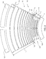
FIG. 2 is an enlarged view of a portion of the inertial sensing system taken alongarea 2 shown inFIG. 1 ; -
FIG. 3 is top view of the inertial sensing system during an oscillation. - Unless otherwise indicated, the drawings provided herein are meant to illustrate features of embodiments of this disclosure. These features are believed to be applicable in a wide variety of systems comprising one or more embodiments of this disclosure. As such, the drawings are not meant to include all conventional features known by those of ordinary skill in the art to be required for the practice of the embodiments disclosed herein.
- In the following specification and the claims, reference will be made to a number of terms, which shall be defined to have the following meanings.
- The singular forms "a", "an", and "the" include plural references unless the context clearly dictates otherwise.
- Approximating language, as used herein throughout the specification and claims, is applied to modify any quantitative representation that could permissibly vary without resulting in a change in the basic function to which it is related. Accordingly, a value modified by a term or terms, such as "about", "approximately", and "substantially", are not to be limited to the precise value specified. In at least some instances, the approximating language may correspond to the precision of an instrument for measuring the value. Here and throughout the specification and claims, range limitations are combined and interchanged, such ranges are identified and include all the sub-ranges contained therein unless context or language indicates otherwise.
- The inertial sensing systems described herein facilitate efficient methods of vibratory gyroscope and accelerometer operation co-fabricated as a unit. Specifically, in contrast to many known inertial sensing systems, the inertial sensing systems as described herein include a novel gyroscope and accelerometer configuration. More specifically, the inertial sensing systems described herein include a gyroscope that defines an inner opening such that the accelerometer is mounted within the opening. Such a configuration allows for a more efficient use of area on the substrate material to which the gyroscope and accelerometer are coupled.
- Furthermore, the inertial sensing system described herein includes a gyroscope that includes a plurality of concentric rings as a proof mass. Specifically, rings having a greater radial length are, in one embodiment, heavier and positioned radially outward from rings having a smaller radial length. As such, the overall proof mass of the gyroscope is increased to increase sensing performance. Moreover, the varying sizes of the rings enable each ring to resonate with the same oscillating amplitude as every other ring when excited by an excitation unit. The gyroscope also includes a plurality of spring elements that each includes a plurality of spring members. The spring members have varying radial lengths similar to the rings. Additionally, the inertial sensing system includes a degree of freedom to use any number of spring elements as necessary to provide for optimal sensing performance. Specifically, the number of spring elements included in the gyroscope is optimized such that the resonant frequency of a drive axis of the gyroscope exactly matches a resonant frequency of a sense axis of the gyroscope. In an alternative embodiment, the number is spring elements in the gyroscope cause the resonant frequency of the drive axis to be different from the resonant frequency of a sense axis.
-
FIG. 1 is a top view of an exemplaryinertial sensing system 100, andFIG. 2 is an enlarged view of a portion ofinertial sensing system 100 taken along area 2 (both shown inFIG. 1 ). In the exemplary embodiment,system 100 includes an axisymmetric Coriolisvibratory gyroscope 102 and anaccelerometer 104. Gyroscope 102 includes at least oneanchor 106, a plurality ofgyroscope spring elements 108, a proof mass including of a plurality ofconcentric rings 110, and an excitation/detection unit 112. In the exemplary embodiment,anchor 106 is the radially innermost component of substantiallycircular gyroscope 102 and defines acentral opening 114 into whichaccelerometer 104 is positioned or located, as described in further detail below. - In one example, the plurality of
gyroscope spring elements 108 are mechanically coupled toanchor 106. More specifically, thegyroscope spring elements 108 are circumferentially-spaced aboutanchor 106 such that thegyroscope spring elements 108 are positioned radially outward from and substantiallyencircle anchor 106. As used herein, the term "encircle" is meant to describe that plurality ofgyroscope spring elements 108, as a whole, substantiallycircumscribe anchor 106. However, because plurality ofgyroscope spring elements 108 is formed from a number of separategyroscope spring elements 108, plurality ofspring elements 108 does not form a complete circle aboutanchor 106. More specifically, plurality ofgyroscope spring elements 108 are circumferentially-spaced aboutanchor 106 such that adjacentgyroscope spring elements 108 are separated by a gap. As such, plurality ofspring elements 108 substantially encirclesanchor 106, but does not necessarily form a complete, unbroken, circle. In the exemplary embodiment,anchor 106 is a continuous substantially circular structure that forms a complete circle definingcentral opening 114. Alternatively,anchor 106 is formed from a plurality of circumferentially-spaced anchor elements (as shown inFIG. 3 ). In such a configuration, eachgyroscope spring element 108 is mechanically coupled to a respective anchor element ofanchor 106. Generally, eachspring element 108 of the plurality ofgyroscope spring elements 108 is coupled to anchor 106 in any manner that enables operation ofgyroscope 102 andinertial sensing system 100 as described herein. - In the exemplary embodiment, the excitation/
detection unit 112 includes a plurality of electrodes that are electrostatically coupled to the concentric rings 110. Alternatively, the excitation/detection unit 112 includes any of optical/photonic devices, magnetic devices, inductive devices, piezoresistive devices, tensoresistive devices, or any combination thereof. Generally, any known method of gyroscope excitation, detection, and tuning may be used withgyroscope 102 that enables operation as described herein. - Referring now to
FIG. 2 , in the exemplary embodiment, the plurality ofgyroscope spring elements 108 includes an overall radial length L1 extending betweenanchor 106 and plurality ofconcentric rings 110. Similarly, plurality ofrings 110 includes an overall radial length L2 extending betweengyroscope spring elements 108 and excitation/detection unit 112. It is noted that some features shown inFIG. 2 are exaggerated andFIG. 2 is not drawn to scale. In one example, the radial length L1 of eachgyroscope spring element 108 is greater than the radial length L2 ofrings 110. Alternatively, in another suitable embodiment, radial length L1 of eachgyroscope spring element 108 is less than or equal to radial length L2 ofrings 110. Generally,gyroscope spring elements 108 and rings 110 have any radial length that facilitates operation ofgyroscope 102 andinertial sensing system 100 as described herein. - In the exemplary embodiment,
gyroscope spring elements 108 include a plurality of foldedspring members 116.Spring members 116 of a respectivegyroscope spring element 108 are radially offset from one another and eachspring member 116 includes a different radial length such that the radial length of each spring member varies betweenanchor 106 and rings 110. More specifically,spring members 116 include afirst spring member 118 positionedadjacent anchor 106 and having a radial length L3. Additionally,spring members 116 include asecond spring member 120 positionedadjacent rings 110 and radially outward fromfirst spring member 118.Second spring member 120 also includes a radial length L4 that is greater than radial length L3. Generally, eachspring member 116 includes a radial length that is greater than a radial length of an immediately adjacent radiallyinner spring member 116 such that eachspring member 116 includes a radial length shorter than a radial length of an immediately successiveouter spring member 116. - In one embodiment, radially
outward spring members 116 are larger and heavier than radiallyinner spring members 116 to provide a larger overall proof mass ofgyroscope 102 to be sensed by excitation/detection unit 112, as described in further detail herein. - As such, when
gyroscope 102 is excited,gyroscope spring elements 108 vibrate with less amplitude in their respective radially inner portionsproximate anchor 106 and vibrate with a greater amplitude in their radially outer portionsproximate rings 110. As described herein, it is desirable thatgyroscope 102 have a large proof mass and a large excitation amplitude to provide for more accurate sensing by excitation/detection unit 112 and, therefore, facilitate improving performance ofgyroscope 102. Alternatively, in another suitable embodiment, eachspring member 116 has a substantially similar radial length. - In the exemplary embodiment, as shown in
FIG. 1 ,gyroscope 102 includes twelvegyroscope spring elements 108 circumferentially-spaced aboutanchor 106. Alternatively,gyroscope 102 includes any number ofgyroscope spring elements 108, such as 11, 15, 17, or 19gyroscope spring elements 108, that facilitate operation ofinertial sensing system 100 as described herein. More specifically, the number ofgyroscope spring elements 108 ingyroscope 102 is optimized such that the resonant frequency of a drive axis ofgyroscope 102 exactly matches a resonant frequency of a sense axis ofgyroscope 102. When the resonant frequencies of the gyroscope drive mode and the sense mode are matched, the signal-to-noise ratio is improved. Such a configuration improves the sensitivity ofinertial sensing system 100 and reduces an amount of mechanical noise sensed byinertial sensing system 100. - Furthermore, because
gyroscope spring elements 108 and rings 110 are separate components ofgyroscope 102,inertial sensing system 100 includes a degree of freedom to use a different number ofgyroscope spring elements 108 thanrings 110 and is not limited to using a gyroscope with only a one-to-one spring-to-ring ratio. The number ofgyroscope spring elements 108 can be optimized based on a number of factors to cause the resonant frequency matching described above. Generally,gyroscope 102 includes any number ofgyroscope spring elements 108 that enableinertial sensing system 100 to operate as described herein. - In the exemplary embodiment, plurality of
rings 110 serve as resonators and are positioned between and mechanically coupled to plurality ofspring elements 108 and communicatively coupled to excitation/detection unit 112.Rings 110 include a plurality ofradial braces 121 circumferentially-spaced betweenadjacent rings 110.Braces 121 are flexible to enable the gap betweenadjacent rings 110 to increase and decrease whengyroscope 102 is excited. Although elevenrings 110 are shown inFIG. 2 ,gyroscope 102 includes any number ofrings 110 that facilitates operation ofgyroscope 102 andinertial sensing system 100 as described herein. For example, the number ofrings 110 ingyroscope 102 is within a range of between approximately 5 rings to approximately 20 rings, and, more specifically, 8 rings. - Similar to
gyroscope spring elements 108, eachring 110 includes a different radial length such that the radial length of eachring 110 varies betweenspring elements 108 and excitation/detection unit 112. More specifically, rings 110 include afirst ring 122 positioned adjacentgyroscope spring elements 108 and having a radial length L5. Additionally, rings 110 include asecond ring 124 positioned adjacent excitation/detection unit 112 and radially outward fromfirst ring 122.Second ring 124 also includes a radial length L6 that is longer than radial length L5. Generally, eachring 110 includes a radial length that is greater than a radial length of an immediately adjacent radiallyinner ring 110 such that eachring 110 includes a radial length shorter than a radial length of an immediately successiveouter ring 110. - In the exemplary embodiment, rings 110 having a greater radial length are heavier than and positioned radially outward from
rings 110 having a smaller radial length to increase the overall proof mass ofgyroscope 102. As described herein, it is desirable thatgyroscope 102 have a large proof mass and a large amplitude to provide for more accurate sensing by excitation/detection unit 112 and, therefore, abetter performing gyroscope 102. Alternatively, in another suitable embodiment, eachring 110 has a substantially similar radial length. Generally, the radial lengths ofrings 110 are optimized such that eachring 110 has a substantially similar amplitude, which maximizes excitation/detection unit 112 sensing and provides for ahigher quality gyroscope 102. As such, in the exemplary embodiment, the varying sizes ofrings 110 enable eachring 110 to have the same oscillating amplitude when excited by at least one electrode of the excitation/detection unit 112. Furthermore, plurality ofrings 110 include a rigidity that is greater than a rigidity ofspring elements 108. - As shown in
FIGS 1 and2 , excitation/detection unit 112 includes electrodes that are circumferentially-spaced aboutrings 110 such that electrodes substantially encircle rings 110. Similar togyroscope spring elements 108 as described above, the term "encircle" is meant to describe that plurality of electrodes, as a whole, substantially circumscribe rings 110. However, because excitation/detection unit 112 is formed from a number of separate electrodes, excitation/detection unit 112 does not form a complete circle about rings 110. More specifically, the plurality of electrodes are circumferentially-spaced aboutrings 110 such that adjacent electrodes are separated by a gap. As such, plurality of electrodes substantially encirclesrings 110, but does not necessarily form a complete, unbroken, circle. In the exemplary embodiment, excitation/detection unit electrodes 112 include at least oneexcitation electrode 126 forexciting rings 110, at least onedetection electrode 128 for measuring an amplitude ofrings 110 during excitation, and at least oneelectrode 130 for quadrature compensating.Gyroscope 102 may also include at least onefeedback electrode 132, called force-rebalance electrode, which increases a bandwidth of the signals. In general, an alternating voltage (AC), or a combination of AC and direct voltage (DC), is applied toexcitation electrode 126 to causerings 110 to oscillate about a drive axis. Asrings 110 oscillate, rings 110 cause the capacitance ofdetection electrode 128 to change. A drive circuit (not shown) monitors the capacitance ofdetection electrode 128 to ascertain the oscillation amplitude ofrings 110. By monitoring the capacitance ofdetection electrodes 128, rings 110 can be suitably controlled to maintain relatively constant oscillation amplitude for a respective mode of operation ofgyroscope 102. -
FIG. 3 illustratesgyroscope 102 excited into resonance mode wine-glass #3. Althoughgyroscope 102 is shown as resonating in wine-glass #3,gyroscope 102 can be operated to resonate in any resonance of wine-glass #2-#5. Additionally,gyroscope 102 is not limited to wine-glass resonance shape, but may be excited into any resonance shape that facilitates operation ofgyroscope 102 as described herein. Furthermore,gyroscope 102 may operate in any known mode of operation, such as, but not limited to, force-rebalance mode, whole-angle mode, and frequency modulated mode.Rings 110 then oscillate based on the excitation mode andgyroscope spring elements 108 are compressed and/or stretched based on the operating mode. More specifically, onespring member 116 of aspring element 108 may compress and anotherspring member 116 of thesame spring element 106 may stretch. Generally,gyroscope spring elements 108 compress and/or stretch to accommodate the shape ofrings 110 as determined by the gyroscope operating mode. - Referring again to
FIG. 1 ,inertial sensing system 100 includesaccelerometer 104 positioned within opening 114 formed byanchor 106 ofgyroscope 102. In the exemplary embodiment,accelerometer 104 includes acentral body portion 134, a plurality ofaccelerometer electrodes 136, and a plurality ofaccelerometer spring elements 138. Similar to excitation/detection unit 112 ofgyroscope 102,accelerometer electrodes 136 are circumferentially-spaced aboutbody portion 134 such thataccelerometer electrodes 136 substantially encirclebody portion 134. As such,accelerometer electrodes 136 are positioned betweenbody portion 134 ofaccelerometer 104 andanchor 106 ofgyroscope 102. Additionally, in the exemplary embodiment,accelerometer spring elements 138 include twospring elements 138 oriented opposite each other with respect tobody portion 134 such thataccelerometer spring elements 138 are mechanically coupled betweenbody portion 134 andanchor 106 ofgyroscope 102. - Furthermore,
inertial sensing system 100 includes asubstrate 140 configured to support bothgyroscope 102 andaccelerometer 104.Substrate 140 may be manufactured using any known MEMS processes and materials, andgyroscope 102 andaccelerometer 104 are micromachined onsubstrate 140. For example,substrate 140 and/or portions of at least one ofgyroscope 102 andaccelerometer 104 may be constructed from silicon and/or quartz. That is, portions ofgyroscope 102 andaccelerometer 104 are co-fabricated onsubstrate 140 using a known etching process withaccelerometer 104 being positioned withincentral opening 114 ofgyroscope 102. As such,gyroscope 102 andaccelerometer 104 are mechanically anchored tosubstrate 140, but may not be mechanically or electrically connected to each other. -
Positioning accelerometer 104 withinopening 114 enables a more efficient use ofsubstrate 140 area rather than positioning an accelerometer adjacent the gyroscope, as in conventional inertial sensing systems. As such,positioning accelerometer 104 withinopening 114 enables asmaller size substrate 140 ininertial sensing system 100 to provide the same system performance as with system having adjacent gyroscopes and accelerometers. Alternatively, within the same substrate area as known inertial sensing systems, the increased proof mass and condensed configuration ofinertial sensing system 100 described herein provides for increased system performance. Furthermore,co-fabricating gyroscope 102 andaccelerometer 104 onsubstrate 140 aligns the sensitivity ofgyroscope 102 andaccelerometer 104 and provides temperature and vibration stability. As a result,gyroscope 102 is calibrated using a signal fromaccelerometer 104, or alternatively,accelerometer 104 is calibrated using a signal fromgyroscope 102. Additionally, co-locatinggyroscope 102 andaccelerometer 104 provides a stress reduction means that results in an increased system performance and cross-calibration where accelerometer calibrates gyroscope signal. - The above described inertial sensing systems facilitate efficient methods of vibratory gyroscope and accelerometer operation. Specifically, in contrast to many known inertial sensing systems, the inertial sensing systems as described herein include a novel gyroscope and accelerometer configuration. More specifically, the inertial sensing systems described herein include a gyroscope that defines an inner opening such that the accelerometer is mounted within the opening. Such a configuration allows for a more efficient use of area on the substrate material to which the gyroscope and accelerometer are coupled. The novel configuration enables a smaller substrate material to provide a substantially similar performance of some known sensing systems. As such, the package that houses the inertial sensing system may be used in smaller applications without sacrificing performance and also costs less to produce. Additionally, the novel configuration enables additional proof mass to be added to the gyroscope to increase the sensing performance of the inertial sensing system while maintaining the same overall package size.
- Furthermore, the inertial sensing system described herein includes a gyroscope that includes a plurality of concentric rings. Specifically, each ring includes a radial length that is greater than a radial length of an immediately adjacent radially inner ring. Rings having a greater radial length are, in one embodiment, heavier than rings having a smaller radial length to increase the overall proof mass of the gyroscope to increase sensing performance. Moreover, the varying sizes of the rings enable each ring to have the same oscillating amplitude as every other ring when excited by the excitation/detection unit. The gyroscope also includes a plurality of spring elements that each include a plurality of spring members. The spring members have varying radial lengths similar to the rings. Additionally, the inertial sensing system includes a degree of freedom to use any number of spring elements as necessary to provide for optimal sensing performance. Specifically, the number of spring elements included in the gyroscope is optimized such that the resonant frequency of a drive axis of the gyroscope exactly matches a resonant frequency of a sense axis.
- An exemplary technical effect of the methods, systems, and apparatus described herein includes at least one of: (a) increasing the sensing performance of the inertial sensing system by varying the size of each of the concentric rings that provide the proof mass and optimizing the number of spring elements; and (b) reducing the manufacturing costs of the inertial sensing system positioning the accelerometer within the gyroscope to enable use of a smaller substrate.
- Exemplary embodiments of methods, systems, and apparatus for manufacturing an inertial sensing system are not limited to the specific embodiments described herein, but rather, components of systems and steps of the methods may be utilized independently and separately from other components and steps described herein. For example, the methods may also be used in combination with other sensing system, and are not limited to practice with only the inertial sensing system and methods as described herein. Rather, the exemplary embodiment can be implemented and utilized in connection with many other applications, equipment, and systems that may benefit from the advantages described herein.
- Although specific features of various embodiments of the disclosure may be shown in some drawings and not in others, this is for convenience only. In accordance with the principles of the disclosure, any feature of a drawing may be referenced and claimed in combination with any feature of any other drawing.
- This written description uses examples to disclose the embodiments, including the best mode, and also to enable any person skilled in the art to practice the embodiments, including making and using any devices or systems and performing any incorporated methods. The patentable scope of the disclosure is defined by the claims, and may include other examples that occur to those skilled in the art. Such other examples are intended to be within the scope of the claims if they have structural elements that do not differ from the literal language of the claims, or if they include equivalent structural elements with insubstantial differences from the literal language of the claims.
- Various aspects and embodiments of the present invention are defined by the following numbered clauses:
- 1. A gyroscope comprising:
- at least one anchor;
- a plurality of gyroscope spring elements coupled to the at least one anchor;
- a plurality of concentric rings, wherein the concentric rings are coupled to the plurality of spring elements, said plurality of concentric rings configured to substantially encircle the plurality of gyroscope spring elements; and
- a detection/excitation unit coupled to said plurality of concentric rings.
- 2. The gyroscope in accordance with clause 1, wherein said at least one anchor defines a central opening configured to receive an accelerometer.
- 3. The gyroscope in accordance with any preceding clause, wherein each spring element of said plurality of spring elements defines a radial length that is greater than a radial length of said plurality of concentric rings.
- 4. The gyroscope in accordance with any preceding clause, wherein each concentric ring of said plurality of concentric rings resonates with a substantially similar amplitude when excited by the detection/excitation unit.
- 5. The gyroscope in accordance with any preceding clause, wherein said detection/excitation unit comprises a plurality of electrodes circumferentially-spaced about said plurality of concentric rings and configured to substantially encircle said plurality of concentric rings.
- 6. The gyroscope in accordance with any preceding clause, wherein the number of spring elements of said plurality of spring elements is based on an operating mode of said gyroscope.
- 7. The gyroscope in accordance with any preceding clause, wherein each spring element comprises a plurality of spring members, wherein a radial length of each spring member of said plurality of spring members varies between said at least one anchor and said plurality of concentric rings.
- 8. The gyroscope in accordance with any preceding clause, wherein each spring member of said plurality of spring members includes a radial length shorter than a radial length of an immediately successive spring member.
- 9. The gyroscope in accordance with any preceding clause, wherein each ring of said plurality of rings includes a radial length shorter than a radial length of an immediately successive ring.
- 10. An inertial sensing system comprising:
- a substrate;
- a gyroscope formed on said substrate, said gyroscope being substantially circular in shape and defining a central opening; and
- an accelerometer formed on said substrate, said accelerometer positioned within the central opening.
- 11. The inertial sensing system in accordance with any preceding clause, wherein said accelerometer comprises a body portion and an detection/excitation unit encircling said body portion, said detection/excitation unit positioned between said body portion and said gyroscope.
- 12. The inertial sensing system in accordance with any preceding clause, wherein said accelerometer further comprises a plurality of spring elements coupled to said body portion and said gyroscope.
- 13. The inertial sensing system in accordance with any preceding clause, wherein said gyroscope comprises:
- at least one anchor;
- a plurality of spring elements coupled to said at least one anchor;
- a plurality of concentric rings coupled to said plurality of spring elements; and
- an excitation/detection unit coupled to said plurality of concentric rings.
- 14. The inertial sensing system in accordance with any preceding clause, wherein said at least one anchor defines the central opening, said accelerometer coupled to said at least one anchor.
- 15. The inertial sensing system in accordance with any preceding clause, wherein said plurality of spring elements are circumferentially-spaced about said at least one anchor.
- 16. The inertial sensing system in accordance with any preceding clause, wherein said plurality of concentric rings substantially encircle said plurality of spring elements and said at least one anchor.
- 17. A method of manufacturing an inertial sensing system comprising a gyroscope that includes at least one anchor, a plurality of circumferentially-spaced spring elements, a plurality of concentric rings, and an excitation/detection unit, said method comprising:
- coupling the plurality of circumferentially-spaced spring elements to the at least one anchor;
- coupling the plurality of concentric rings to the plurality of circumferentially-spaced spring elements, wherein the plurality of rings substantially encircle the plurality of spring elements; and
- coupling the excitation/detection unit to the plurality of concentric rings.
- 18. The method in accordance with any preceding clause, wherein coupling the excitation/detection unit to the plurality of concentric rings comprises coupling a plurality of circumferentially-spaced electrodes to the plurality of rings such that the plurality of electrodes substantially encircle the plurality of spring elements.
- 19. The method in accordance with any preceding clause, wherein the inertial sensing system further includes an accelerometer that includes a body portion, a plurality of electrodes, and a second plurality of spring elements, said method further comprising positioning the accelerometer within a central opening defined by the at least one anchor.
- 20. The method in accordance with any preceding clause, further comprising:
- coupling the second plurality of spring elements between the body portion and the at least one anchor; and
- positioning the plurality of electrodes between the body portion and the at least one anchor.
- a body portion;
- a detection/excitation unit encircling said body portion, said detection/excitation unit positioned between said body portion and said gyroscope;
4a. The gyroscope in accordance with any preceding clause, wherein each spring element of said plurality of spring elements defines a radial length that is greater than a radial length of said plurality of concentric rings.
Claims (15)
- A gyroscope comprising:at least one anchor;a plurality of spring elements, each spring element being defined by a group of radially offset spring members;wherein each spring element of the plurality of spring elements is coupled to, and circumferentially spaced about, the at least one anchor such that adjacent groups of radially offset spring members defining each spring element of the plurality of spring elements are radially separated by a gap; andwherein each spring member of the group of radially offset spring members comprises a radial length different from the other spring members of the group of radially offset spring members;a proof mass comprising a plurality of concentric rings operatively coupled to the plurality of spring elements, the plurality of concentric rings encircling the plurality of spring elements; anda detection/excitation unit (i) coupled to the plurality of concentric rings and (ii) configured to sense an angular rate of the proof mass.
- The gyroscope in accordance with claim 1, wherein said at least one anchor defines a central opening configured to receive an accelerometer.
- The gyroscope in accordance with any preceding claim, wherein each concentric ring of the plurality of concentric rings resonates with a substantially similar amplitude when excited by the detection/excitation unit.
- The gyroscope in accordance with any preceding claim, wherein the detection/excitation unit comprises a plurality of electrodes circumferentially spaced about the plurality of concentric rings and configured to substantially encircle the plurality of concentric rings.
- The gyroscope in accordance with any preceding claim, wherein the number of spring elements of the plurality of spring elements is based on an operating mode of the gyroscope.
- The gyroscope in accordance with any preceding claim, wherein each spring member of each group of radially offset spring members includes a radial length greater than a radial length of an immediately adjacent radially inner spring member.
- The gyroscope in accordance with any preceding claim, wherein each group of radially offset spring members includes a first spring member having a first radial length and a second spring member having a second radial length, wherein the second radial length is greater than the first radial length.
- The gyroscope in accordance with claim 7, wherein the second spring member of each group of radially offset spring members is positioned radially outward from the first spring member.
- The gyroscope in accordance with claim 7, wherein the second spring member of each group of radially offset spring members is positioned proximate the proof mass and the first spring member is positioned proximate the at least one anchor.
- The gyroscope in accordance with any preceding claim, wherein the plurality each group of spring elements circumscribe the at least one anchor.
- The gyroscope in accordance with any preceding claim, wherein each concentric ring comprises a radial length different than each other concentric ring of said plurality of concentric rings.
- The gyroscope in accordance with any preceding claim, wherein a number of concentric rings of the plurality of concentric rings is based on an operating mode of the gyroscope.
- The gyroscope in accordance with any preceding claim, wherein each concentric ring of the plurality of concentric rings includes a radial length greater than a radial length of an immediately adjacent radially inner concentric ring.
- The gyroscope in accordance with any preceding claim, wherein the plurality of concentric rings includes a first concentric ring having a first radial length and a second concentric ring having a second radial length, wherein the second radial length is greater than the first radial length.
- The gyroscope in accordance with claim 14, wherein the second concentric ring is positioned radially outward from the first concentric ring; or wherein the second concentric ring is positioned proximate the excitation/detection unit, and the first concentric ring is positioned proximate the plurality of spring elements.
Applications Claiming Priority (3)
| Application Number | Priority Date | Filing Date | Title |
|---|---|---|---|
| US201562154384P | 2015-04-29 | 2015-04-29 | |
| US14/931,939 US10502568B2 (en) | 2015-04-29 | 2015-11-04 | Inertial sensing systems and methods of manufacturing the same |
| EP16167402.3A EP3091361B1 (en) | 2015-04-29 | 2016-04-28 | Inertial sensing systems and methods of manufacturing the same |
Related Parent Applications (2)
| Application Number | Title | Priority Date | Filing Date |
|---|---|---|---|
| EP16167402.3A Division-Into EP3091361B1 (en) | 2015-04-29 | 2016-04-28 | Inertial sensing systems and methods of manufacturing the same |
| EP16167402.3A Division EP3091361B1 (en) | 2015-04-29 | 2016-04-28 | Inertial sensing systems and methods of manufacturing the same |
Publications (1)
| Publication Number | Publication Date |
|---|---|
| EP4102234A1 true EP4102234A1 (en) | 2022-12-14 |
Family
ID=55854717
Family Applications (2)
| Application Number | Title | Priority Date | Filing Date |
|---|---|---|---|
| EP16167402.3A Active EP3091361B1 (en) | 2015-04-29 | 2016-04-28 | Inertial sensing systems and methods of manufacturing the same |
| EP22189348.0A Pending EP4102234A1 (en) | 2015-04-29 | 2016-04-28 | Inertial sensing systems and methods of manufacturing the same |
Family Applications Before (1)
| Application Number | Title | Priority Date | Filing Date |
|---|---|---|---|
| EP16167402.3A Active EP3091361B1 (en) | 2015-04-29 | 2016-04-28 | Inertial sensing systems and methods of manufacturing the same |
Country Status (3)
| Country | Link |
|---|---|
| US (2) | US10502568B2 (en) |
| EP (2) | EP3091361B1 (en) |
| CA (1) | CA2927495A1 (en) |
Families Citing this family (9)
| Publication number | Priority date | Publication date | Assignee | Title |
|---|---|---|---|---|
| US10180323B2 (en) * | 2014-06-09 | 2019-01-15 | The Regents Of The University Of California | Axi-symmetric small-footprint gyroscope with interchangeable whole-angle and rate operation |
| WO2017075413A1 (en) | 2015-10-28 | 2017-05-04 | Georgia Tech Research Corporation | Comb-driven substrate decoupled annulus pitch/roll baw gyroscope with slanted quadrature tuning electrode |
| ITUA20162172A1 (en) * | 2016-03-31 | 2017-10-01 | St Microelectronics Srl | ACCELEROMETRIC SENSOR MADE IN MEMS TECHNOLOGY WITH HIGH ACCURACY AND REDUCED SENSITIVITY TOWARDS TEMPERATURE AND AGING |
| WO2018057071A1 (en) | 2016-06-07 | 2018-03-29 | Georgia Tech Research Corporation | Pitch/roll annulus gyroscope with slanted quadrature tuning electrodes and related fabrication methods |
| CN109489649A (en) * | 2018-12-27 | 2019-03-19 | 瑞声声学科技(深圳)有限公司 | MEMS gyroscope and electronic equipment comprising the gyroscope |
| CN214149332U (en) * | 2020-07-09 | 2021-09-07 | 瑞声科技(南京)有限公司 | MEMS gyroscope and electronic product |
| CN213090780U (en) * | 2020-07-09 | 2021-04-30 | 瑞声科技(南京)有限公司 | MEMS gyroscope and electronic product |
| DE102022114406A1 (en) | 2022-06-08 | 2023-12-14 | Northrop Grumman Litef Gmbh | Microelectromechanical coupling device |
| DE102023117380A1 (en) * | 2023-06-30 | 2025-01-02 | Northrop Grumman Litef Gmbh | microelectromechanical coupling device |
Citations (3)
| Publication number | Priority date | Publication date | Assignee | Title |
|---|---|---|---|---|
| WO2004015372A1 (en) * | 2002-08-12 | 2004-02-19 | The Boeing Company | Isolated planar gyroscope with internal radial sensing and actuation |
| WO2011026100A1 (en) * | 2009-08-31 | 2011-03-03 | Georgia Tech Research Corporation | Bulk acoustic wave gyroscope with spoked structure |
| US20130160578A1 (en) * | 2011-05-25 | 2013-06-27 | The Regents Of The University Of Michigan | Gyroscope and method of fabricating a resonator for a gyroscope |
Family Cites Families (21)
| Publication number | Priority date | Publication date | Assignee | Title |
|---|---|---|---|---|
| US5450751A (en) | 1993-05-04 | 1995-09-19 | General Motors Corporation | Microstructure for vibratory gyroscope |
| US6584845B1 (en) * | 1999-02-10 | 2003-07-01 | California Institute Of Technology | Inertial sensor and method of use |
| WO2000068640A2 (en) | 1999-04-21 | 2000-11-16 | The Regents Of The University Of California | Micro-machined angle-measuring gyroscope |
| US7040163B2 (en) | 2002-08-12 | 2006-05-09 | The Boeing Company | Isolated planar gyroscope with internal radial sensing and actuation |
| US7581443B2 (en) | 2005-07-20 | 2009-09-01 | The Boeing Company | Disc resonator gyroscopes |
| UA79166C2 (en) | 2005-05-31 | 2007-05-25 | Yurii Oleksiiovych Yatsenko | Detecting element of a vibratory gyroscope sensitive to coriolis acceleration |
| US7281426B1 (en) | 2006-06-15 | 2007-10-16 | Innalabs Technologies, Inc. | Stemless hemispherical resonator gyroscope |
| US7493814B2 (en) | 2006-12-22 | 2009-02-24 | The Boeing Company | Vibratory gyroscope with parasitic mode damping |
| US7793541B2 (en) | 2007-06-04 | 2010-09-14 | The Boeing Company | Planar resonator gyroscope central die attachment |
| DE102007030119A1 (en) | 2007-06-29 | 2009-01-02 | Litef Gmbh | Coriolis |
| US8333112B2 (en) | 2008-06-10 | 2012-12-18 | The Boeing Company | Frequency tuning of disc resonator gyroscopes via resonator mass perturbation based on an identified model |
| US8205495B2 (en) | 2008-06-10 | 2012-06-26 | The Boeing Company | Systematic disc resonator gyroscope tuning |
| US8011246B2 (en) | 2008-09-22 | 2011-09-06 | Northrop Grumman Guidance And Electronics Company, Inc. | Apparatus and method for self-calibration of coriolis vibratory gyroscope |
| IT1394007B1 (en) * | 2009-05-11 | 2012-05-17 | St Microelectronics Rousset | MICROELETTROMECANICAL STRUCTURE WITH IMPROVED REJECTION OF ACCELERATION DISORDERS |
| US8567247B2 (en) | 2009-10-12 | 2013-10-29 | The Regents Of The University Of California | Three-dimensional wafer-scale batch-micromachined sensor and method of fabrication for the same |
| EP3009792B1 (en) | 2010-11-19 | 2018-02-14 | Innalabs Limited | Gyroscope |
| US8448513B2 (en) | 2011-10-05 | 2013-05-28 | Freescale Semiconductor, Inc. | Rotary disk gyroscope |
| US20140013845A1 (en) | 2012-07-13 | 2014-01-16 | Robert E. Stewart | Class ii coriolis vibratory rocking mode gyroscope with central fixed post |
| CN105043370B (en) * | 2014-04-29 | 2019-01-22 | 财团法人工业技术研究院 | Micro-motor device with fulcrum element |
| US10180323B2 (en) * | 2014-06-09 | 2019-01-15 | The Regents Of The University Of California | Axi-symmetric small-footprint gyroscope with interchangeable whole-angle and rate operation |
| US10746548B2 (en) * | 2014-11-04 | 2020-08-18 | Analog Devices, Inc. | Ring gyroscope structural features |
-
2015
- 2015-11-04 US US14/931,939 patent/US10502568B2/en active Active
-
2016
- 2016-04-21 CA CA2927495A patent/CA2927495A1/en not_active Abandoned
- 2016-04-28 EP EP16167402.3A patent/EP3091361B1/en active Active
- 2016-04-28 EP EP22189348.0A patent/EP4102234A1/en active Pending
-
2019
- 2019-08-23 US US16/549,760 patent/US11326883B2/en active Active
Patent Citations (3)
| Publication number | Priority date | Publication date | Assignee | Title |
|---|---|---|---|---|
| WO2004015372A1 (en) * | 2002-08-12 | 2004-02-19 | The Boeing Company | Isolated planar gyroscope with internal radial sensing and actuation |
| WO2011026100A1 (en) * | 2009-08-31 | 2011-03-03 | Georgia Tech Research Corporation | Bulk acoustic wave gyroscope with spoked structure |
| US20130160578A1 (en) * | 2011-05-25 | 2013-06-27 | The Regents Of The University Of Michigan | Gyroscope and method of fabricating a resonator for a gyroscope |
Also Published As
| Publication number | Publication date |
|---|---|
| US20200011667A1 (en) | 2020-01-09 |
| EP3091361B1 (en) | 2022-09-28 |
| US20170067742A1 (en) | 2017-03-09 |
| EP3091361A1 (en) | 2016-11-09 |
| US11326883B2 (en) | 2022-05-10 |
| CA2927495A1 (en) | 2016-10-29 |
| US10502568B2 (en) | 2019-12-10 |
Similar Documents
| Publication | Publication Date | Title |
|---|---|---|
| US11326883B2 (en) | Inertial sensing systems and methods of manufacturing the same | |
| AU2007336930B2 (en) | Vibratory gyroscope with parasitic mode damping | |
| US10809061B2 (en) | Vibratory gyroscope including a plurality of inertial bodies | |
| CN1148564C (en) | Gyroscope | |
| US5915276A (en) | Rate sensor | |
| KR100594957B1 (en) | Angular velocity sensor | |
| US20160123735A1 (en) | Ring Gyroscope Structural Features | |
| EP3574286B1 (en) | A method of optimising the performance of a mems rate gyroscope | |
| JP6997043B2 (en) | Angular velocity sensor | |
| EP3470784B1 (en) | Angular rate sensors | |
| EP1064519A1 (en) | A two axis gyroscope | |
| KR100493149B1 (en) | Symmetrical Z-axis gyroscope and fabricating method thereof | |
| EP1425553A1 (en) | Vibratory gyroscopic rate sensor | |
| KR20040031089A (en) | Vibratory gyroscopic rate sensor | |
| Kassie et al. | Geometrical Mode-Matching in a (100) Single-Crystalline Silicon, Smooth-Quatrefoil Disk Resonator |
Legal Events
| Date | Code | Title | Description |
|---|---|---|---|
| PUAI | Public reference made under article 153(3) epc to a published international application that has entered the european phase |
Free format text: ORIGINAL CODE: 0009012 |
|
| STAA | Information on the status of an ep patent application or granted ep patent |
Free format text: STATUS: THE APPLICATION HAS BEEN PUBLISHED |
|
| AC | Divisional application: reference to earlier application |
Ref document number: 3091361 Country of ref document: EP Kind code of ref document: P |
|
| AK | Designated contracting states |
Kind code of ref document: A1 Designated state(s): AL AT BE BG CH CY CZ DE DK EE ES FI FR GB GR HR HU IE IS IT LI LT LU LV MC MK MT NL NO PL PT RO RS SE SI SK SM TR |
|
| STAA | Information on the status of an ep patent application or granted ep patent |
Free format text: STATUS: REQUEST FOR EXAMINATION WAS MADE |
|
| 17P | Request for examination filed |
Effective date: 20230523 |
|
| RBV | Designated contracting states (corrected) |
Designated state(s): AL AT BE BG CH CY CZ DE DK EE ES FI FR GB GR HR HU IE IS IT LI LT LU LV MC MK MT NL NO PL PT RO RS SE SI SK SM TR |
|
| STAA | Information on the status of an ep patent application or granted ep patent |
Free format text: STATUS: EXAMINATION IS IN PROGRESS |
|
| 17Q | First examination report despatched |
Effective date: 20250721 |
|
| GRAP | Despatch of communication of intention to grant a patent |
Free format text: ORIGINAL CODE: EPIDOSNIGR1 |
|
| STAA | Information on the status of an ep patent application or granted ep patent |
Free format text: STATUS: GRANT OF PATENT IS INTENDED |