EP4102172B1 - Multi-faceted shot - Google Patents
Multi-faceted shot Download PDFInfo
- Publication number
- EP4102172B1 EP4102172B1 EP22153855.6A EP22153855A EP4102172B1 EP 4102172 B1 EP4102172 B1 EP 4102172B1 EP 22153855 A EP22153855 A EP 22153855A EP 4102172 B1 EP4102172 B1 EP 4102172B1
- Authority
- EP
- European Patent Office
- Prior art keywords
- projectile
- ring
- diameter
- sections
- pole
- Prior art date
- Legal status (The legal status is an assumption and is not a legal conclusion. Google has not performed a legal analysis and makes no representation as to the accuracy of the status listed.)
- Active
Links
Images



Classifications
-
- F—MECHANICAL ENGINEERING; LIGHTING; HEATING; WEAPONS; BLASTING
- F42—AMMUNITION; BLASTING
- F42B—EXPLOSIVE CHARGES, e.g. FOR BLASTING, FIREWORKS, AMMUNITION
- F42B7/00—Shotgun ammunition
-
- F—MECHANICAL ENGINEERING; LIGHTING; HEATING; WEAPONS; BLASTING
- F42—AMMUNITION; BLASTING
- F42B—EXPLOSIVE CHARGES, e.g. FOR BLASTING, FIREWORKS, AMMUNITION
- F42B7/00—Shotgun ammunition
- F42B7/02—Cartridges, i.e. cases with propellant charge and missile
- F42B7/04—Cartridges, i.e. cases with propellant charge and missile of pellet type
- F42B7/046—Pellets or shot therefor
-
- F—MECHANICAL ENGINEERING; LIGHTING; HEATING; WEAPONS; BLASTING
- F42—AMMUNITION; BLASTING
- F42B—EXPLOSIVE CHARGES, e.g. FOR BLASTING, FIREWORKS, AMMUNITION
- F42B12/00—Projectiles, missiles or mines characterised by the warhead, the intended effect, or the material
- F42B12/72—Projectiles, missiles or mines characterised by the warhead, the intended effect, or the material characterised by the material
- F42B12/76—Projectiles, missiles or mines characterised by the warhead, the intended effect, or the material characterised by the material of the casing
Definitions
- the present invention generally relates to projectiles, particularly shotshell pellets, for use in a shotgun.
- shotshell pellets also referred to as "shot" for a shotgun ammunition system (“cartridges” or “shotshells”).
- Shotshells are typically filled with shotshell pellet of a uniform size, classified according to the nominal diameter of the pellet along with the material (e.g., lead, steel, non-toxic alloys, and the like) and the intended target. Standard sizes have developed for different intended targets, for example ranging from 000 buckshot (0.36 inch (in.) diameter (dia.), or 9.144 millimeter (mm) dia.) to 5 (0.12 in. dia., or 3.048 mm dia.) or 6 (0.11 in. dia., or 2.794 mm dia.) to 9 (0.08 in. dia., or 2.032 mm dia.) and smaller shots.
- a plurality of such shotshell pellets are loaded in a shotshell comprising a casing defining an internal chamber that also includes propellant and a primer.
- US7765933B2 discloses a shotshell with shot pellets having multiple shapes.
- a pellet or ammunition projectile for use in a shotshell for a shotgun comprises a top pole, a bottom pole, an equator, a plurality of sections extending between the poles and equator, and a ring at the equator, as detailed in claim 1.
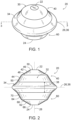
- FIGURES 1-2 show a projectile 20 constructed in accordance with embodiments of the invention.
- the projectile 20 comprises a top pole 22 and a bottom pole 24 that are generally or substantially flat disc-like sections.
- the top pole 22 and the bottom pole 24 are substantially equidistant from a vertical center 26 and that define a vertical axis 28 through the top and bottom poles 22, 24.
- the projectile 20 also includes a body 30 defining an exterior surface 32 and having a ring 34, one or more upper sections 40, and one or more lower sections 60.
- the ring 34 protrudes from an equator 36 about which the body 30 may be substantially symmetric, i.e., divided into upper and lower hemispheres.
- the ring 34 also defines a vertical ring height 38.
- the one or more upper sections 40 extend between the equator 36 and the top pole 22.
- a plurality of upper sections 40 are provided that, when viewed in cross-section ( FIGS. 3A and 3B ), are defined by first and second walls 42, 44 that are substantially flat and are disposed at different angles relative to the vertical axis 28. Any number of walls is contemplated, including embodiments with one, two, three, four, or more walls defining the one or more upper sections 40.
- the body 30 of the projectile 20 defines a plurality of corners between sections, the plurality of corners being angular and including a first corner 46 between the top pole 22 and the first wall 42, a second corner 48 between the first wall 42 and the second wall 44, and a third corner 50 between the second wall 44 and the ring 34.
- Each of the one or more upper sections 40 defines a substantially frustoconical shape.
- each of the first corner 46, second corner 48, and third corner 50 defines a substantially circular shape about the vertical axis 28.
- the plurality of upper sections 40 and the plurality of lower sections 60 constitute sides forming interrupted surfaces between the ring 34 and the respective the top pole 22 and bottom pole 24.
- the body 30 is interrupted in the upper sections 40 by the first wall 42 and the second wall 44 extending at different angles relative to the vertical axis 28, forming angular steps that define the first corner 46, second corner 48, and third corner 50.
- the body 30 is interrupted in the lower sections 60 by the first wall 62 and the second wall 64 extending at different angles relative to the vertical axis 28, forming angular steps that define the first corner 66, second corner 58, and third corner 70.
- the one or more lower sections 60 extend between the equator 36 and the bottom pole 24.
- a plurality of lower sections 60 are provided that, when viewed in cross-section ( FIGS. 3A and 3B ), are defined by first and second walls 62, 64 that are substantially flat and are disposed at different angles relative to the vertical axis 28. Any number of walls is contemplated, including embodiments with one, two, three, four, or more walls defining the one or more lower sections 60.
- the body 30 of the projectile defines a plurality of corners or inflection points between walls and poles, including a first corner 66 between the bottom pole 24 and the first wall 62, a second corner 68 between the first wall 62 and the second wall 64, and a third corner 70 between the second wall 64 and the ring 34.
- each of the first corner 66, second corner 68, and third corner 70 defines a substantially circular shape about the vertical axis 28.
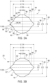
- FIGS. 3A and 3B illustrate how embodiments of the present disclosure provide a multi-faceted shot that is not spherical.
- the projectile 20 has several stepped surfaces including the frustoconical walls 42, 44, 62, 64, such surfaces together providing angular steps between the ring 34 and the poles 22, 24.
- the top and bottom poles 22, 24 are flat sections.
- the embodiment of FIGS. 1-4 provides a multi-faceted exterior surface 32 and does not include any three-dimensionally curved surfaces that could define a portion of a sphere, let alone any such curved surfaces across a majority of the exterior surface 32 of the projectile 20.
- FIG. 3A shows particular dimensions for the projectile 20 applicable to embodiments of the present disclosure.
- the illustrated projectile 20 is in the class of a #5 birdshot (0.12 in. (3.048 mm) diameter). It will be appreciated that various other sizes are contemplated while maintaining similar relative dimensions of the constituent parts of the projectile 20. These dimensions include the ring height 38, a vertical diameter 80, a second corner height 82, a horizontal diameter 84 for the ring 34 at the equator 36, a pole diameter 86 (also considered a first circle diameter 86), a second circle diameter 88, and a third circle diameter 90.
- the ring 34 also defines a ring angle 92 measured between an upper wall 94 and a lower wall 96 of the ring 34. The ring angle may be about 83 degrees, about 80 - 90 degrees, or about 75 - 95 degrees.
- the vertical diameter 80 and third circle diameter 90 are 101% and 102%, respectively, of the standard 0.12 in. diameter for a #5 shot.
- the projectile 20 is not spherical, these dimensions define the closest analogue in standard spherical shots, allowing for similar uses (e.g., hunting similar game as with the corresponding standard).
- the horizontal diameter 84 is appreciably larger and constitutes 130% of the standard diameter, which produces the ring 34, that projects out from the more "standard" dimension of a #5 shot (or another size shot). In other words, the ring 34 projects out substantially further than the dimensions 80, 90 that more closely correspond to a standard sized shot.
- embodiments applicable to the present disclosure may have vertical and third circle diameters 80, 90 within about 95% - 105% of the standard diameter of a given shot size, or within about 90% - 110% of such standard diameter.
- Table 1 Selected Standard Shot Dimensions American Size English Size European Size Pellet Diameter (in.) 000 - - 0.36 00 - - 0.34 0 - - 0.32 #1 Buck - - 0.30 #3 Buck - - 0.25 #4 Buck - - 0.24 F - - 0.22 T - - 0.20 BBB BBB - 0.19 BB BB - 0.18 1 B 1 0.16 2 1 2 0.15 3 2 3 0.14 4 3 4 0.13 5 4 5 0.12 6 5 6 0.11 7 6 7 0.10 7 1 ⁇ 2 6 1 ⁇ 2 - 0.095 8 7 8 0.09 8 1 ⁇ 2 8 - 0.085 9 9 9 0.08 9 1 ⁇ 2 - - 0.075 10 10 10 0.07
- the other dimensions shown in FIG. 3A may be derived and implemented as a function of the vertical diameter 80 and/or the third circle diameter 90.
- the vertical ring height 38 measured relative to either the vertical diameter 80 or the third circle diameter 90 may be 30-40%, about 29-31%, or about 33-36%.
- Table 1 below shows dimensions expressed as a function of another determined dimension.
- Table 2 Relative Dimensions and Prototype #5 Shot Dimensions Dimension Relative to Standard Diameter Relative to Vertical Diameter Relative to Horizontal Diameter Manufactured Size Range for #5 Shot Embodiment of This Invention
- Vertical Diameter 80 90 - 110% - 70 - 100% 0.111 ⁇ .002 in.
- Horizontal Diameter 84 100 - 140% 100 - 140% - 0.148 ⁇ .002 in.
- the variability in dimensions shown above in the last column of Table 1 is due to various manufacturing tolerances, tooling precision, material variability (e.g. degree of compaction of powdered material before pressing), and the like. Accordingly, in these manufactured embodiments the ratio of the vertical ring height 38 to the vertical diameter 80 ranges from 35-36% and the ratio of the vertical ring height 38 to the horizontal diameter 84 ranges from 33-35%. Additionally, the ring angle 92 in these manufactured embodiments can range from about 85-93 degrees.
- FIG. 3B shows particular dimensions for the projectile 20 applicable to certain embodiments of the present disclosure in the class of a #6 birdshot (0.11 in. (2.792 mm) diameter). It will be appreciated that the relative dimensions in this embodiment correspond to the ranges of values in Table 1 above. For example, the illustrated vertical diameter 80 and third circle diameter 90 are 94% and 95%, respectively, of the standard 0.11 in. diameter for a #6 shot.
- shot as described above can be formed from various selected materials including lead, steel, tungsten, alloys thereof, green materials, or the like.
- shot 20 as described herein can be made from powder components and be formed using a powder press.
- the powder press comprises a lower hemispherical cavity, an upper hemispherical cavity and a plate in between the two cavities comprising a central ring-shaped opening.
- the ring-shaped opening may be cylindrical or may have other desired shapes to form the equatorial ring 34 on the projectile 20 having a shape described above.
- Powder components placed in the cavities within the ring may be combined with lubricants and/or binders and are pressed to the desired shape.
- the shot 20 described above may be sintered.
- the equatorial ring 34 may be made larger for ease of manufacture.
- the ring height 38 may be between about 40 - 45% of the vertical height 80.
- the band can be made between about 2.0 mm and 2.25 mm in its width.
- the ring height 38 in some embodiments can be reduced to about 25 - 30% of the vertical height 80.
- shot as disclosed may be manufactured using a ball header process.
- Ball header machines are particularly suitable for forming steel shot.
- a steel wire may be fed into the header, the wire having a diameter smaller than the desired diameter of the final shot.
- the header will cut the wire, and two heading cavities will be pressed toward the ends of the wire.
- shot having the shapes described above may be formed, particularly with the desired shape and size of the ring 34.
- the ring 34 is desirably formed between the two heading cavities beyond the edges of the two cavities.
- Embodiments of the shot described above advantageously improve the manufacturing, aerodynamics, ballistics, and terminal performance of the shot.
- the disclosed embodiments are readily adaptable to high-volume and low-cost manufacturing processes, such as those discussed above.
- a user may fire a shotgun shell including the shots (projectiles) as described above.
- the equatorial ring 34 and/or the corners 46, 48, 50, 66, 68, 70 provide cutting surfaces for increased penetration.
- the ring 34 and overall shape may affect the trajectory of the shots, which can desirably improve the spray size and/or consistency, velocity, and/or distance of the shot traveling to the target.
- a projectile 520 includes top pole 522 and a bottom pole (not shown) that are arranged with a depressed circular surface 523 inside an outer ring 525.
- the outer ring may be a flat frustoconical surface, a concave surface, or a convex surface.
- the depressed circular surface 523 may be substantially flat, or (in examples not covered by the claims) convex, or concave.
- FIGS. 6-9 show a variety of alternative embodiments applicable to the present disclosure.
- Figures 7 and 8 are not covered by the claims.
- One or more of the illustrated features may be applicable to any other disclosed embodiment in part or in whole, including the embodiments of FIGS. 1-3 and 5 . It will be appreciated that these features may affect certain dimensions listed in Table 2 without significantly affecting the ring height 38, vertical height 80, second corner height 82, first circle diameter 86, and the horizontal diameter 84.
- FIG. 6 shows an embodiment of a projectile 620 comprising a top pole 602 and a single upper section 640 extending to a ring 634.
- a ring 635 has an angular waist 635 at an equator 636.
- a lower section 660 has a plurality of dimples 661 for improving aerodynamics.
- FIG. 7 shows an embodiment of a projectile 720 comprising poles and walls that are curved concave or convex, such as a concave top pole 702 and a concave wall 764 of a plurality of lower sections 760.
- the shot may include a convex bottom pole 704 or a convex wall 744 of a plurality of upper sections 740.
- a ring 734 may likewise have a convex portion 735 or a concave portion 737 formed therein.
- These various curved surfaces may be defined by different radii of curvature or substantially equal radii of curvature.
- curved inflection points may be provided between the poles and walls or between the walls and ring may be provided in lieu of the corners shown in other embodiments.
- FIG. 8 shows an embodiment of a projectile 820 with a ring 834 defined by a substantially vertical wall 835 extending between a plurality of upper sections 840 and a plurality of lower sections 860, resulting in a substantially 12-sided cross-sectional form. This embodiment may result in a reduced horizontal diameter compared to other embodiments.
- FIG. 9 shows an embodiment of a projectile 920 comprising a ring 934 formed of substantially flat walls 935, 937, and 939.
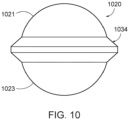
- FIG. 10 shows an embodiment not covered by the claims of a projectile 1020 comprising a ring 1034 that is substantially similar to the ring 34 of FIGS. 1-4 .
- a substantially spherical upper hemisphere 1021 and a substantially spherical lower hemisphere 1023 extend from the ring 1034, providing a rounded shape without the corners or substantially flat walls and poles of other embodiments.
- FIG. 11 shows an embodiment of a projectile 1120 shown in an exploded view that is similar to the projectile 20 of FIGS. 1-4 .
- the illustrated brackets indicate areas of selectably variable or indeterminate length formed of the same material as the rest of the projectile and otherwise having substantially the same profile.
- the projectile may be longer or shorter in horizontal and/or vertical directions as indicated by the brackets.
- Such variations in length may result in the projectile 1120 being oblong in either the vertical or horizontal direction.
Landscapes
- Engineering & Computer Science (AREA)
- General Engineering & Computer Science (AREA)
- Physics & Mathematics (AREA)
- Thermal Sciences (AREA)
- Chemical & Material Sciences (AREA)
- Combustion & Propulsion (AREA)
- Prostheses (AREA)
- Containers Having Bodies Formed In One Piece (AREA)
- Toys (AREA)
Description
- The present invention generally relates to projectiles, particularly shotshell pellets, for use in a shotgun.
- Exemplary embodiments disclosed herein relate to shotshell pellets (also referred to as "shot") for a shotgun ammunition system ("cartridges" or "shotshells"). Shotshells are typically filled with shotshell pellet of a uniform size, classified according to the nominal diameter of the pellet along with the material (e.g., lead, steel, non-toxic alloys, and the like) and the intended target. Standard sizes have developed for different intended targets, for example ranging from 000 buckshot (0.36 inch (in.) diameter (dia.), or 9.144 millimeter (mm) dia.) to 5 (0.12 in. dia., or 3.048 mm dia.) or 6 (0.11 in. dia., or 2.794 mm dia.) to 9 (0.08 in. dia., or 2.032 mm dia.) and smaller shots. Typically, a plurality of such shotshell pellets are loaded in a shotshell comprising a casing defining an internal chamber that also includes propellant and a primer.
-
US7765933B2 discloses a shotshell with shot pellets having multiple shapes. - A pellet or ammunition projectile for use in a shotshell for a shotgun comprises a top pole, a bottom pole, an equator, a plurality of sections extending between the poles and equator, and a ring at the equator, as detailed in claim 1.
- The invention can be completely understood in consideration of the following detailed description of various embodiments of the invention in connection with the accompanying drawings, in which:
-
FIG. 1 is a front perspective view of a shotgun projectile in accord with embodiments of the present disclosure. -
FIG. 2 is a side elevation view of the shotgun projectile ofFIG. 1 . -
FIG. 3A is a side cross-sectional view of the shotgun projectile ofFIG. 1 taken along the line 3-3 inFIG. 1 in accord with a #5 shot embodiment of the present disclosure. -
FIG. 3B is a side cross-sectional view of the shotgun projectile ofFIG. 1 taken along the line 3-3 inFIG. 1 in accord with a #6 shot embodiment of the present disclosure. -
FIG. 4 is a top view of the shotgun projectile ofFIG. 1 . -
FIG. 5 is a front perspective view of a shotgun projectile in accord with embodiments of the present disclosure. -
FIG. 6 is a side view of a shotgun projectile in accord with embodiments of the present disclosure. -
FIG. 7 is a side view of a shotgun projectile in accord with embodiments of the present disclosure. -
FIG. 8 is a side view of a shotgun projectile in accord with embodiments of the present disclosure. -
FIG. 9 is a side view of a shotgun projectile in accord with embodiments of the present disclosure. -
FIG. 10 is a side view of a shotgun projectile in accord with embodiments of the present disclosure. -
FIG. 11 is a perspective view of a shotgun projectile in accord with embodiments of the present disclosure. - While the invention is amenable to various modifications and alternative forms, specifics thereof have been depicted by way of example in the drawings and will be described in detail. It should be understood, however, that the intention is not to limit the invention to the particular embodiments described. On the contrary, the intention is to cover all modifications, equivalents, and alternatives falling within the scope of the invention as defined by the appended claims.
-
FIGURES 1-2 show aprojectile 20 constructed in accordance with embodiments of the invention. Theprojectile 20 comprises atop pole 22 and abottom pole 24 that are generally or substantially flat disc-like sections. Thetop pole 22 and thebottom pole 24 are substantially equidistant from a vertical center 26 and that define avertical axis 28 through the top andbottom poles projectile 20 also includes abody 30 defining anexterior surface 32 and having aring 34, one or moreupper sections 40, and one or morelower sections 60. Thering 34 protrudes from an equator 36 about which thebody 30 may be substantially symmetric, i.e., divided into upper and lower hemispheres. Thering 34 also defines avertical ring height 38. - The one or more
upper sections 40 extend between the equator 36 and thetop pole 22. In certain embodiments, a plurality ofupper sections 40 are provided that, when viewed in cross-section (FIGS. 3A and 3B ), are defined by first andsecond walls vertical axis 28. Any number of walls is contemplated, including embodiments with one, two, three, four, or more walls defining the one or moreupper sections 40. Thebody 30 of theprojectile 20 defines a plurality of corners between sections, the plurality of corners being angular and including afirst corner 46 between thetop pole 22 and thefirst wall 42, asecond corner 48 between thefirst wall 42 and thesecond wall 44, and athird corner 50 between thesecond wall 44 and thering 34. Each of the one or moreupper sections 40 defines a substantially frustoconical shape. In certain embodiments shown inFIG. 4 , each of thefirst corner 46,second corner 48, andthird corner 50 defines a substantially circular shape about thevertical axis 28. In a general sense, the plurality ofupper sections 40 and the plurality oflower sections 60 constitute sides forming interrupted surfaces between thering 34 and the respective thetop pole 22 andbottom pole 24. Thebody 30 is interrupted in theupper sections 40 by thefirst wall 42 and thesecond wall 44 extending at different angles relative to thevertical axis 28, forming angular steps that define thefirst corner 46,second corner 48, andthird corner 50. Likewise thebody 30 is interrupted in thelower sections 60 by thefirst wall 62 and thesecond wall 64 extending at different angles relative to thevertical axis 28, forming angular steps that define thefirst corner 66, second corner 58, andthird corner 70. - The one or more
lower sections 60 extend between the equator 36 and thebottom pole 24. In some embodiments, a plurality oflower sections 60 are provided that, when viewed in cross-section (FIGS. 3A and 3B ), are defined by first andsecond walls vertical axis 28. Any number of walls is contemplated, including embodiments with one, two, three, four, or more walls defining the one or morelower sections 60. Thebody 30 of the projectile defines a plurality of corners or inflection points between walls and poles, including afirst corner 66 between thebottom pole 24 and thefirst wall 62, asecond corner 68 between thefirst wall 62 and thesecond wall 64, and athird corner 70 between thesecond wall 64 and thering 34. In certain embodiments similar to theupper section 40 shown inFIG. 4 , each of thefirst corner 66,second corner 68, andthird corner 70 defines a substantially circular shape about thevertical axis 28. -
FIGS. 3A and 3B illustrate how embodiments of the present disclosure provide a multi-faceted shot that is not spherical. Theprojectile 20 has several stepped surfaces including thefrustoconical walls ring 34 and thepoles bottom poles FIGS. 1-4 provides a multi-facetedexterior surface 32 and does not include any three-dimensionally curved surfaces that could define a portion of a sphere, let alone any such curved surfaces across a majority of theexterior surface 32 of theprojectile 20. -
FIG. 3A shows particular dimensions for theprojectile 20 applicable to embodiments of the present disclosure. The illustratedprojectile 20 is in the class of a #5 birdshot (0.12 in. (3.048 mm) diameter). It will be appreciated that various other sizes are contemplated while maintaining similar relative dimensions of the constituent parts of the projectile 20. These dimensions include thering height 38, avertical diameter 80, asecond corner height 82, ahorizontal diameter 84 for thering 34 at the equator 36, a pole diameter 86 (also considered a first circle diameter 86), asecond circle diameter 88, and athird circle diameter 90. Thering 34 also defines aring angle 92 measured between anupper wall 94 and alower wall 96 of thering 34. The ring angle may be about 83 degrees, about 80 - 90 degrees, or about 75 - 95 degrees. - In the embodiment of
FIG. 3A , thevertical diameter 80 andthird circle diameter 90 are 101% and 102%, respectively, of the standard 0.12 in. diameter for a #5 shot. Although the projectile 20 is not spherical, these dimensions define the closest analogue in standard spherical shots, allowing for similar uses (e.g., hunting similar game as with the corresponding standard). In embodiments, thehorizontal diameter 84 is appreciably larger and constitutes 130% of the standard diameter, which produces thering 34, that projects out from the more "standard" dimension of a #5 shot (or another size shot). In other words, thering 34 projects out substantially further than thedimensions third circle diameters Table 1: Selected Standard Shot Dimensions American Size English Size European Size Pellet Diameter (in.) 000 - - 0.36 00 - - 0.34 0 - - 0.32 #1 Buck - - 0.30 #3 Buck - - 0.25 #4 Buck - - 0.24 F - - 0.22 T - - 0.20 BBB BBB - 0.19 BB BB - 0.18 1 B 1 0.16 2 1 2 0.15 3 2 3 0.14 4 3 4 0.13 5 4 5 0.12 6 5 6 0.11 7 6 7 0.10 7 ½ 6 ½ - 0.095 8 7 8 0.09 8 ½ 8 - 0.085 9 9 9 0.08 9 ½ - - 0.075 10 10 10 0.07 - The other dimensions shown in
FIG. 3A may be derived and implemented as a function of thevertical diameter 80 and/or thethird circle diameter 90. Notably, in embodiments not covered by the claims thevertical ring height 38 measured relative to either thevertical diameter 80 or thethird circle diameter 90 may be 30-40%, about 29-31%, or about 33-36%. As such, Table 1 below shows dimensions expressed as a function of another determined dimension. Additionally, the last column in Table 2 lists measured dimensions for manufactured prototypes of the #5 shot ofFIG. 3A , wherein 1 inch = 25,4 mm.Table 2: Relative Dimensions and Prototype #5 Shot Dimensions Dimension Relative to Standard Diameter Relative to Vertical Diameter Relative to Horizontal Diameter Manufactured Size Range for #5 Shot Embodiment of This Invention Vertical Diameter 80 90 - 110% - 70 - 100% 0.111 ± .002 in. Horizontal Diameter 84100 - 140% 100 - 140% - 0.148 ± .002 in. Pole Diameter 86 - 20 - 35% 15-25% 0.037 ± .005 in. Second Circle Diameter 88 - 70 - 80% 55 - 65% 0.084 ± .001 in. Third Circle Diameter 9090 - 110% 90 - 110% 70 - 100% 0.116 ± .002 in. Ring Height 38 - 21 - 50% 15 - 35% 0.0396 ± .010 in. Second Corner Height 82 - 65 - 80% 50 - 60% 0.083 ± .010 in. - The variability in dimensions shown above in the last column of Table 1 is due to various manufacturing tolerances, tooling precision, material variability (e.g. degree of compaction of powdered material before pressing), and the like. Accordingly, in these manufactured embodiments the ratio of the
vertical ring height 38 to thevertical diameter 80 ranges from 35-36% and the ratio of thevertical ring height 38 to thehorizontal diameter 84 ranges from 33-35%. Additionally, thering angle 92 in these manufactured embodiments can range from about 85-93 degrees. -
FIG. 3B shows particular dimensions for the projectile 20 applicable to certain embodiments of the present disclosure in the class of a #6 birdshot (0.11 in. (2.792 mm) diameter). It will be appreciated that the relative dimensions in this embodiment correspond to the ranges of values in Table 1 above. For example, the illustratedvertical diameter 80 andthird circle diameter 90 are 94% and 95%, respectively, of the standard 0.11 in. diameter for a #6 shot. - In certain embodiments, shot as described above can be formed from various selected materials including lead, steel, tungsten, alloys thereof, green materials, or the like.
- In certain embodiments, shot 20 as described herein can be made from powder components and be formed using a powder press. The powder press comprises a lower hemispherical cavity, an upper hemispherical cavity and a plate in between the two cavities comprising a central ring-shaped opening. The ring-shaped opening may be cylindrical or may have other desired shapes to form the
equatorial ring 34 on the projectile 20 having a shape described above. Powder components placed in the cavities within the ring may be combined with lubricants and/or binders and are pressed to the desired shape. - In embodiments, the
shot 20 described above may be sintered. For a sintered shot, theequatorial ring 34 may be made larger for ease of manufacture. For example, for a 3 to 5 mm diameter high density shot, thering height 38 may be between about 40 - 45% of thevertical height 80. For a 5 mm sintered shot, the band can be made between about 2.0 mm and 2.25 mm in its width. For a sintered shot larger than about 5 mm, thering height 38 in some embodiments can be reduced to about 25 - 30% of thevertical height 80. - In other embodiments, shot as disclosed may be manufactured using a ball header process. Ball header machines are particularly suitable for forming steel shot. For example, a steel wire may be fed into the header, the wire having a diameter smaller than the desired diameter of the final shot. The header will cut the wire, and two heading cavities will be pressed toward the ends of the wire. By adjusting the pressure applied by the header, shot having the shapes described above may be formed, particularly with the desired shape and size of the
ring 34. Thering 34 is desirably formed between the two heading cavities beyond the edges of the two cavities. - Embodiments of the shot described above advantageously improve the manufacturing, aerodynamics, ballistics, and terminal performance of the shot. The disclosed embodiments are readily adaptable to high-volume and low-cost manufacturing processes, such as those discussed above. For an example of ballistic improvement, in a method of using the shot, a user may fire a shotgun shell including the shots (projectiles) as described above. When the shot impacts the desired target, the
equatorial ring 34 and/or thecorners ring 34 and overall shape may affect the trajectory of the shots, which can desirably improve the spray size and/or consistency, velocity, and/or distance of the shot traveling to the target. - As shown in
FIG. 5 , a projectile 520 includestop pole 522 and a bottom pole (not shown) that are arranged with a depressedcircular surface 523 inside anouter ring 525. The outer ring may be a flat frustoconical surface, a concave surface, or a convex surface. The depressedcircular surface 523 may be substantially flat, or (in examples not covered by the claims) convex, or concave. -
FIGS. 6-9 show a variety of alternative embodiments applicable to the present disclosure.Figures 7 and8 are not covered by the claims. One or more of the illustrated features may be applicable to any other disclosed embodiment in part or in whole, including the embodiments ofFIGS. 1-3 and5 . It will be appreciated that these features may affect certain dimensions listed in Table 2 without significantly affecting thering height 38,vertical height 80,second corner height 82,first circle diameter 86, and thehorizontal diameter 84.FIG. 6 shows an embodiment of a projectile 620 comprising a top pole 602 and a singleupper section 640 extending to aring 634. Aring 635 has anangular waist 635 at anequator 636. In other embodiments, alower section 660 has a plurality ofdimples 661 for improving aerodynamics. -
FIG. 7 shows an embodiment of a projectile 720 comprising poles and walls that are curved concave or convex, such as a concavetop pole 702 and aconcave wall 764 of a plurality oflower sections 760. The shot may include a convexbottom pole 704 or aconvex wall 744 of a plurality ofupper sections 740. Aring 734 may likewise have aconvex portion 735 or aconcave portion 737 formed therein. These various curved surfaces may be defined by different radii of curvature or substantially equal radii of curvature. Likewise it will be appreciate that curved inflection points may be provided between the poles and walls or between the walls and ring may be provided in lieu of the corners shown in other embodiments. -
FIG. 8 shows an embodiment of a projectile 820 with aring 834 defined by a substantiallyvertical wall 835 extending between a plurality ofupper sections 840 and a plurality oflower sections 860, resulting in a substantially 12-sided cross-sectional form. This embodiment may result in a reduced horizontal diameter compared to other embodiments. -
FIG. 9 shows an embodiment of a projectile 920 comprising aring 934 formed of substantiallyflat walls -
FIG. 10 shows an embodiment not covered by the claims of a projectile 1020 comprising aring 1034 that is substantially similar to thering 34 ofFIGS. 1-4 . In this embodiment, a substantially sphericalupper hemisphere 1021 and a substantially sphericallower hemisphere 1023 extend from thering 1034, providing a rounded shape without the corners or substantially flat walls and poles of other embodiments. -
FIG. 11 shows an embodiment of a projectile 1120 shown in an exploded view that is similar to the projectile 20 ofFIGS. 1-4 . However, in this embodiment, the illustrated brackets indicate areas of selectably variable or indeterminate length formed of the same material as the rest of the projectile and otherwise having substantially the same profile. In this manner, the projectile may be longer or shorter in horizontal and/or vertical directions as indicated by the brackets. Such variations in length may result in the projectile 1120 being oblong in either the vertical or horizontal direction.
Claims (10)
- An ammunition projectile (20) for a shotshell, comprising:a body (30) comprising an upper section (40) having a top pole (22) comprising a substantially flat disc, a lower section (60) having a bottom pole (24) comprising a substantially flat disc, and an equator (36) between the upper and lower sections;the top and bottom poles defining a vertical axis (28) of the projectile;the body defining an exterior surface (32) and a vertical diameter (80) from the top pole to the bottom pole;a ring (34) protruding from the equator of the body, characterized in that the ring height (38) comprises about 28% - 40% of the vertical diameter (80) of the body; and in that the upper section and the lower section each have a plurality of frustoconical walls at different angles relative to the vertical axis.
- The projectile (20) of claim 1, wherein:the top pole (22) and the bottom pole (24) are equidistant from a vertical center (26) of the projectile;the body is substantially symmetric about the equator;the ring height (38) comprising about 33 - 36% of the vertical diameter of the body,the body comprising:a plurality of upper sections (40) extending between the equator and the top pole and defining a first upper corner (46) at an intersection with the top pole;a plurality of lower sections (60) extending between the equator and the bottom pole and defining a first lower corner (66) at an intersection with the bottom pole; andthe top and bottom poles being substantially circular and delineated respectively by the first upper corner and the first lower corner.
- The projectile of claim 2, the body further comprising a plurality of corners (48, 50) at intersections of the plurality of upper sections and a plurality of corners (58, 70) at intersections of the plurality of lower sections.
- The projectile (20) of any of claims 1 to 3, wherein the ring (24) encircles and is substantially symmetric about the equator (26) of the body (30).
- The projectile (20) of any of claims 1 to 4, wherein the ring (34) defines a horizontal diameter (84) that is greater than the vertical height (80) of the body (30).
- The projectile (20) of any of claims 1 to 5, wherein:the top pole (22) and the bottom pole (24) are equidistant from a center of the projectile;the ring (34) defines a horizontal diameter (84) that is greater than the vertical height of the body, the ring encircling and substantially symmetric about the equator;the upper section (740) extending between the ring and the top section and defining varying distances from the center; andthe lower section (840) extending between the ring and the bottom section and defining varying distances from the center.
- The projectile (20) of claim 3 or 6, wherein the ring (34) defines a horizontal diameter; and wherein the plurality of corners encircle the vertical axis defining diameters within a range from about 15% to about 85% of the horizontal diameter.
- The projectile of claim 3 or any of claims 6 to 7, wherein the ring defines a horizontal diameter, and wherein the plurality of corners encircle the vertical axis to definea first circle comprising a diameter (86) within a range of about 15-25% of the horizontal diameter, and/or within a range of about 0.020"-0.030" (0.020 in. to 0.030 in., or 0.508 mm to 0.762 mm); and to definea second circle comprising a diameter (88) within a range of about 55-65% of the horizontal diameter, and/or within a range of about 0.075"-0.085" (0.075 in. to 0.085 in., or 1.905 mm to 2.159 mm); and to definea third circle comprising a diameter (90) within a range of about 75-85% of the horizontal diameter, and/or within a range of about 0.100"-0.120" (0.100 in. to 0.120 in., or 2.540 mm to 3.048 mm).
- The projectile (20) of any of claims 6 to 8, wherein the one or more upper sections, when viewed in cross-section, comprise two or more upper sections formed as curved walls with different radii; and
wherein the one or more lower sections, when viewed in cross-section, comprise two or more lower sections formed as curved walls with different radii. - The projectile (20) of any of claims 6 to 9, the body further comprising an inflection point between sections of the one or more upper sections and an inflection point between sections of the one or more lower sections.
Applications Claiming Priority (1)
| Application Number | Priority Date | Filing Date | Title |
|---|---|---|---|
| US17/162,848 US11519703B2 (en) | 2021-01-29 | 2021-01-29 | Multi-faceted shot |
Publications (3)
| Publication Number | Publication Date |
|---|---|
| EP4102172A1 EP4102172A1 (en) | 2022-12-14 |
| EP4102172B1 true EP4102172B1 (en) | 2024-08-28 |
| EP4102172C0 EP4102172C0 (en) | 2024-08-28 |
Family
ID=80122884
Family Applications (1)
| Application Number | Title | Priority Date | Filing Date |
|---|---|---|---|
| EP22153855.6A Active EP4102172B1 (en) | 2021-01-29 | 2022-01-28 | Multi-faceted shot |
Country Status (5)
| Country | Link |
|---|---|
| US (3) | US11519703B2 (en) |
| EP (1) | EP4102172B1 (en) |
| CN (1) | CN114812289A (en) |
| AU (1) | AU2022200518B2 (en) |
| CA (1) | CA3146955A1 (en) |
Families Citing this family (1)
| Publication number | Priority date | Publication date | Assignee | Title |
|---|---|---|---|---|
| USD1101093S1 (en) * | 2021-01-29 | 2025-11-04 | Federal Cartridge Company | Projectile |
Family Cites Families (43)
| Publication number | Priority date | Publication date | Assignee | Title |
|---|---|---|---|---|
| US1583559A (en) * | 1925-11-02 | 1926-05-04 | Christian H Kenneweg | Shotgun cartridge |
| US2394524A (en) | 1943-04-30 | 1946-02-05 | Armstrong Cork Co | Method of making cork composition cartridge plugs |
| US3123003A (en) | 1962-01-03 | 1964-03-03 | lange | |
| US3579767A (en) | 1969-06-02 | 1971-05-25 | Gen Impact Extrusions Mfg Ltd | Method for forming flash holes in cartridge cases |
| US3756155A (en) * | 1970-12-28 | 1973-09-04 | D Smith | Shot gun shells |
| US3726218A (en) | 1971-02-02 | 1973-04-10 | Us Army | Low velocity cartridge having total propellant ignition |
| US3952659A (en) * | 1974-06-20 | 1976-04-27 | Olin Corporation | Flattened spherical shot |
| US4610205A (en) | 1984-07-30 | 1986-09-09 | Bentley John C | Bullet for black powder rifles |
| US4996924A (en) * | 1987-08-11 | 1991-03-05 | Mcclain Harry T | Aerodynamic air foil surfaces for in-flight control for projectiles |
| US5020438A (en) | 1989-10-10 | 1991-06-04 | Brown Jim W | Bladed projectile |
| US5713981A (en) * | 1992-05-05 | 1998-02-03 | Teledyne Industries, Inc. | Composite shot |
| US5831188A (en) * | 1992-05-05 | 1998-11-03 | Teledyne Industries, Inc. | Composite shots and methods of making |
| SE506479C2 (en) * | 1995-03-28 | 1997-12-22 | Boliden Mineral Ab | Hail for wet hunting and the production of such hail |
| US5798478A (en) | 1997-04-16 | 1998-08-25 | Cove Corporation | Ammunition projectile having enhanced flight characteristics |
| GB2370873B (en) | 2001-01-09 | 2004-11-17 | Eley Ltd | Ammunition cartridge |
| US6955125B1 (en) | 2002-02-26 | 2005-10-18 | The United States Of America As Represented By The Secretary Of The Army | Practice projectile with smoke signature |
| US7503260B2 (en) | 2006-02-15 | 2009-03-17 | Defense Technology Corporation Of America | Non-lethal ammunition |
| US8122832B1 (en) * | 2006-05-11 | 2012-02-28 | Spherical Precision, Inc. | Projectiles for shotgun shells and the like, and methods of manufacturing the same |
| EP1884737B1 (en) * | 2006-08-03 | 2018-05-16 | Saltech AG | Rubber pellet package |
| US7765933B2 (en) * | 2007-11-06 | 2010-08-03 | Alliant Techsystems Inc. | Shotshell with shot pellets having multiple shapes |
| RU2400696C1 (en) * | 2009-09-23 | 2010-09-27 | Общество с ограниченной ответственностью "ТехКомплект" | Armor piercing bullet core and method of its fabrication |
| US20110185936A1 (en) * | 2010-01-08 | 2011-08-04 | Richardson Matthew D | Shotshell with combination load for personal defense |
| USD633166S1 (en) * | 2010-01-15 | 2011-02-22 | Olin Corporation | Disc-shaped projectile for a shot shell |
| USD773008S1 (en) | 2010-10-20 | 2016-11-29 | Olin Corporation | Shot |
| US8726778B2 (en) * | 2011-02-16 | 2014-05-20 | Ervin Industries, Inc. | Cost-effective high-volume method to produce metal cubes with rounded edges |
| EP2686635B1 (en) * | 2011-03-16 | 2016-03-09 | Olin Corporation | Rounded cubic shot and shotshells loaded with rounded cubic shot |
| US20130263754A1 (en) | 2012-03-01 | 2013-10-10 | Richard Neme | Ammunition Rounds for Observance of Religious Beliefs and a Method of Hunting |
| USD683419S1 (en) | 2012-04-12 | 2013-05-28 | Peter D. Rebar | Lead-free airgun pellet |
| US9534876B2 (en) * | 2013-05-28 | 2017-01-03 | Ra Brands, L.L.C. | Projectile and mold to cast projectile |
| US9541362B2 (en) | 2014-01-24 | 2017-01-10 | Ward Kraft, Inc. | Customizable projectile designed to tumble |
| USD732635S1 (en) | 2014-02-11 | 2015-06-23 | Gamo Outdoor Usa | Airgun pellet |
| US10323918B2 (en) * | 2014-07-29 | 2019-06-18 | Polywad, Inc. | Auto-segmenting spherical projectile |
| RU2597431C2 (en) | 2014-08-26 | 2016-09-10 | Андрей Альбертович Половнев | Bullet ammunition for small arms |
| USD764624S1 (en) | 2014-10-13 | 2016-08-23 | Olin Corporation | Shouldered round nose bullet |
| USD782602S1 (en) | 2015-03-18 | 2017-03-28 | Sig Sauer, Inc. | Pellet |
| USD782601S1 (en) | 2015-03-18 | 2017-03-28 | Sig Sauer, Inc. | Pellet |
| USD780282S1 (en) | 2015-03-18 | 2017-02-28 | Sig Sauer, Inc. | Pellet |
| US10317178B2 (en) | 2015-04-21 | 2019-06-11 | The United States Of America, As Represented By The Secretary Of The Navy | Optimized subsonic projectiles and related methods |
| USD781993S1 (en) | 2015-07-29 | 2017-03-21 | Crosman Corporation | Domed airgun pellet |
| US10222188B2 (en) * | 2016-01-15 | 2019-03-05 | Joshua M. Kunz | Projectile with enhanced ballistic efficiency |
| US20190154421A1 (en) * | 2017-11-21 | 2019-05-23 | Amick Family Revocable Living Trust | Firearm projectiles with turbulence-inducing surfaces, firearm cartridges including the same, and associated methods |
| CN110375594A (en) * | 2019-06-28 | 2019-10-25 | 南京理工大学 | A kind of supercavity long-tail projectile entering water suitable for low-angle |
| CN211205061U (en) * | 2019-12-30 | 2020-08-07 | 中国人民解放军陆军装甲兵学院 | Novel electromagnetic weapon bullet |
-
2021
- 2021-01-29 US US17/162,848 patent/US11519703B2/en active Active
-
2022
- 2022-01-27 AU AU2022200518A patent/AU2022200518B2/en active Active
- 2022-01-28 EP EP22153855.6A patent/EP4102172B1/en active Active
- 2022-01-28 CA CA3146955A patent/CA3146955A1/en active Pending
- 2022-02-07 CN CN202210115731.5A patent/CN114812289A/en active Pending
- 2022-12-02 US US18/074,193 patent/US11940259B2/en active Active
-
2024
- 2024-02-22 US US18/584,087 patent/US12345515B2/en active Active
Also Published As
| Publication number | Publication date |
|---|---|
| CA3146955A1 (en) | 2022-07-29 |
| US20230168070A1 (en) | 2023-06-01 |
| US11519703B2 (en) | 2022-12-06 |
| EP4102172A1 (en) | 2022-12-14 |
| US11940259B2 (en) | 2024-03-26 |
| US20240247920A1 (en) | 2024-07-25 |
| US20220244026A1 (en) | 2022-08-04 |
| US12345515B2 (en) | 2025-07-01 |
| EP4102172C0 (en) | 2024-08-28 |
| AU2022200518B2 (en) | 2024-02-22 |
| AU2022200518A1 (en) | 2022-08-18 |
| CN114812289A (en) | 2022-07-29 |
Similar Documents
| Publication | Publication Date | Title |
|---|---|---|
| US7765933B2 (en) | Shotshell with shot pellets having multiple shapes | |
| US8122832B1 (en) | Projectiles for shotgun shells and the like, and methods of manufacturing the same | |
| US3877381A (en) | Shotgun pellet arrangement | |
| US6959648B2 (en) | Ammunition cartridge | |
| US3289586A (en) | Wad column | |
| EP2686635B1 (en) | Rounded cubic shot and shotshells loaded with rounded cubic shot | |
| US20070289475A1 (en) | Non-lethal munitions having densified materials | |
| JP2003524137A (en) | Powder based disc for gun ammunition | |
| US12345515B2 (en) | Multi-faceted shot | |
| WO2011085279A2 (en) | Shotshell with combination load for personal defense | |
| US11953300B2 (en) | Metallic solid projectile, tool arrangement and method for producing metallic solid projectiles | |
| US4479438A (en) | Saboted shot | |
| US5347932A (en) | Shot wad with highly collapsible hinge portion | |
| KR101916598B1 (en) | Fragmentation liner inducing formation of uniform size and method of manufacturing the same | |
| KR101808483B1 (en) | Method for manufacturing the controlled fragmentation warhead and fragmentation liner | |
| EP0779967A1 (en) | Projectiles having controllable density and mass distribution | |
| CN216205713U (en) | Projectile | |
| RU2096738C1 (en) | Bullet for guns "tandem 1pt" | |
| KR101175565B1 (en) | Fragment for shell and production method thereof | |
| CN120800103A (en) | Sniping bullet warhead with drag reduction structure | |
| WO2002090869A3 (en) | Solid outer skin powder-base disc for projectiles |
Legal Events
| Date | Code | Title | Description |
|---|---|---|---|
| PUAI | Public reference made under article 153(3) epc to a published international application that has entered the european phase |
Free format text: ORIGINAL CODE: 0009012 |
|
| STAA | Information on the status of an ep patent application or granted ep patent |
Free format text: STATUS: THE APPLICATION HAS BEEN PUBLISHED |
|
| AK | Designated contracting states |
Kind code of ref document: A1 Designated state(s): AL AT BE BG CH CY CZ DE DK EE ES FI FR GB GR HR HU IE IS IT LI LT LU LV MC MK MT NL NO PL PT RO RS SE SI SK SM TR |
|
| STAA | Information on the status of an ep patent application or granted ep patent |
Free format text: STATUS: REQUEST FOR EXAMINATION WAS MADE |
|
| RAP1 | Party data changed (applicant data changed or rights of an application transferred) |
Owner name: FEDERAL CARTRIDGE COMPANY |
|
| 17P | Request for examination filed |
Effective date: 20230605 |
|
| RBV | Designated contracting states (corrected) |
Designated state(s): AL AT BE BG CH CY CZ DE DK EE ES FI FR GB GR HR HU IE IS IT LI LT LU LV MC MK MT NL NO PL PT RO RS SE SI SK SM TR |
|
| GRAP | Despatch of communication of intention to grant a patent |
Free format text: ORIGINAL CODE: EPIDOSNIGR1 |
|
| STAA | Information on the status of an ep patent application or granted ep patent |
Free format text: STATUS: GRANT OF PATENT IS INTENDED |
|
| INTG | Intention to grant announced |
Effective date: 20240111 |
|
| GRAJ | Information related to disapproval of communication of intention to grant by the applicant or resumption of examination proceedings by the epo deleted |
Free format text: ORIGINAL CODE: EPIDOSDIGR1 |
|
| STAA | Information on the status of an ep patent application or granted ep patent |
Free format text: STATUS: REQUEST FOR EXAMINATION WAS MADE |
|
| GRAP | Despatch of communication of intention to grant a patent |
Free format text: ORIGINAL CODE: EPIDOSNIGR1 |
|
| STAA | Information on the status of an ep patent application or granted ep patent |
Free format text: STATUS: GRANT OF PATENT IS INTENDED |
|
| INTC | Intention to grant announced (deleted) | ||
| INTG | Intention to grant announced |
Effective date: 20240607 |
|
| GRAS | Grant fee paid |
Free format text: ORIGINAL CODE: EPIDOSNIGR3 |
|
| GRAA | (expected) grant |
Free format text: ORIGINAL CODE: 0009210 |
|
| STAA | Information on the status of an ep patent application or granted ep patent |
Free format text: STATUS: THE PATENT HAS BEEN GRANTED |
|
| AK | Designated contracting states |
Kind code of ref document: B1 Designated state(s): AL AT BE BG CH CY CZ DE DK EE ES FI FR GB GR HR HU IE IS IT LI LT LU LV MC MK MT NL NO PL PT RO RS SE SI SK SM TR |
|
| REG | Reference to a national code |
Ref country code: CH Ref legal event code: EP |
|
| REG | Reference to a national code |
Ref country code: DE Ref legal event code: R096 Ref document number: 602022005555 Country of ref document: DE |
|
| REG | Reference to a national code |
Ref country code: IE Ref legal event code: FG4D |
|
| U01 | Request for unitary effect filed |
Effective date: 20240906 |
|
| U07 | Unitary effect registered |
Designated state(s): AT BE BG DE DK EE FI FR IT LT LU LV MT NL PT RO SE SI Effective date: 20241002 |
|
| PG25 | Lapsed in a contracting state [announced via postgrant information from national office to epo] |
Ref country code: NO Free format text: LAPSE BECAUSE OF FAILURE TO SUBMIT A TRANSLATION OF THE DESCRIPTION OR TO PAY THE FEE WITHIN THE PRESCRIBED TIME-LIMIT Effective date: 20241128 |
|
| PG25 | Lapsed in a contracting state [announced via postgrant information from national office to epo] |
Ref country code: PL Free format text: LAPSE BECAUSE OF FAILURE TO SUBMIT A TRANSLATION OF THE DESCRIPTION OR TO PAY THE FEE WITHIN THE PRESCRIBED TIME-LIMIT Effective date: 20240828 Ref country code: GR Free format text: LAPSE BECAUSE OF FAILURE TO SUBMIT A TRANSLATION OF THE DESCRIPTION OR TO PAY THE FEE WITHIN THE PRESCRIBED TIME-LIMIT Effective date: 20241129 |
|
| PG25 | Lapsed in a contracting state [announced via postgrant information from national office to epo] |
Ref country code: IS Free format text: LAPSE BECAUSE OF FAILURE TO SUBMIT A TRANSLATION OF THE DESCRIPTION OR TO PAY THE FEE WITHIN THE PRESCRIBED TIME-LIMIT Effective date: 20241228 |
|
| PG25 | Lapsed in a contracting state [announced via postgrant information from national office to epo] |
Ref country code: HR Free format text: LAPSE BECAUSE OF FAILURE TO SUBMIT A TRANSLATION OF THE DESCRIPTION OR TO PAY THE FEE WITHIN THE PRESCRIBED TIME-LIMIT Effective date: 20240828 |
|
| PG25 | Lapsed in a contracting state [announced via postgrant information from national office to epo] |
Ref country code: ES Free format text: LAPSE BECAUSE OF FAILURE TO SUBMIT A TRANSLATION OF THE DESCRIPTION OR TO PAY THE FEE WITHIN THE PRESCRIBED TIME-LIMIT Effective date: 20240828 Ref country code: RS Free format text: LAPSE BECAUSE OF FAILURE TO SUBMIT A TRANSLATION OF THE DESCRIPTION OR TO PAY THE FEE WITHIN THE PRESCRIBED TIME-LIMIT Effective date: 20241128 |
|
| PG25 | Lapsed in a contracting state [announced via postgrant information from national office to epo] |
Ref country code: RS Free format text: LAPSE BECAUSE OF FAILURE TO SUBMIT A TRANSLATION OF THE DESCRIPTION OR TO PAY THE FEE WITHIN THE PRESCRIBED TIME-LIMIT Effective date: 20241128 Ref country code: PL Free format text: LAPSE BECAUSE OF FAILURE TO SUBMIT A TRANSLATION OF THE DESCRIPTION OR TO PAY THE FEE WITHIN THE PRESCRIBED TIME-LIMIT Effective date: 20240828 Ref country code: NO Free format text: LAPSE BECAUSE OF FAILURE TO SUBMIT A TRANSLATION OF THE DESCRIPTION OR TO PAY THE FEE WITHIN THE PRESCRIBED TIME-LIMIT Effective date: 20241128 Ref country code: IS Free format text: LAPSE BECAUSE OF FAILURE TO SUBMIT A TRANSLATION OF THE DESCRIPTION OR TO PAY THE FEE WITHIN THE PRESCRIBED TIME-LIMIT Effective date: 20241228 Ref country code: HR Free format text: LAPSE BECAUSE OF FAILURE TO SUBMIT A TRANSLATION OF THE DESCRIPTION OR TO PAY THE FEE WITHIN THE PRESCRIBED TIME-LIMIT Effective date: 20240828 Ref country code: GR Free format text: LAPSE BECAUSE OF FAILURE TO SUBMIT A TRANSLATION OF THE DESCRIPTION OR TO PAY THE FEE WITHIN THE PRESCRIBED TIME-LIMIT Effective date: 20241129 Ref country code: ES Free format text: LAPSE BECAUSE OF FAILURE TO SUBMIT A TRANSLATION OF THE DESCRIPTION OR TO PAY THE FEE WITHIN THE PRESCRIBED TIME-LIMIT Effective date: 20240828 |
|
| PG25 | Lapsed in a contracting state [announced via postgrant information from national office to epo] |
Ref country code: SM Free format text: LAPSE BECAUSE OF FAILURE TO SUBMIT A TRANSLATION OF THE DESCRIPTION OR TO PAY THE FEE WITHIN THE PRESCRIBED TIME-LIMIT Effective date: 20240828 |
|
| PG25 | Lapsed in a contracting state [announced via postgrant information from national office to epo] |
Ref country code: SK Free format text: LAPSE BECAUSE OF FAILURE TO SUBMIT A TRANSLATION OF THE DESCRIPTION OR TO PAY THE FEE WITHIN THE PRESCRIBED TIME-LIMIT Effective date: 20240828 |
|
| U21 | Renewal fee for the european patent with unitary effect paid with additional fee |
Year of fee payment: 4 Effective date: 20250416 |
|
| PLBE | No opposition filed within time limit |
Free format text: ORIGINAL CODE: 0009261 |
|
| STAA | Information on the status of an ep patent application or granted ep patent |
Free format text: STATUS: NO OPPOSITION FILED WITHIN TIME LIMIT |
|
| 26N | No opposition filed |
Effective date: 20250530 |
|
| REG | Reference to a national code |
Ref country code: CH Ref legal event code: PL |
|
| PG25 | Lapsed in a contracting state [announced via postgrant information from national office to epo] |
Ref country code: MC Free format text: LAPSE BECAUSE OF FAILURE TO SUBMIT A TRANSLATION OF THE DESCRIPTION OR TO PAY THE FEE WITHIN THE PRESCRIBED TIME-LIMIT Effective date: 20240828 |
|
| PG25 | Lapsed in a contracting state [announced via postgrant information from national office to epo] |
Ref country code: CH Free format text: LAPSE BECAUSE OF NON-PAYMENT OF DUE FEES Effective date: 20250131 |
|
| PG25 | Lapsed in a contracting state [announced via postgrant information from national office to epo] |
Ref country code: IE Free format text: LAPSE BECAUSE OF NON-PAYMENT OF DUE FEES Effective date: 20250128 |
|
| U20 | Renewal fee for the european patent with unitary effect paid |
Year of fee payment: 5 Effective date: 20260127 |
|
| PGFP | Annual fee paid to national office [announced via postgrant information from national office to epo] |
Ref country code: GB Payment date: 20260127 Year of fee payment: 5 |
|
| PGFP | Annual fee paid to national office [announced via postgrant information from national office to epo] |
Ref country code: CZ Payment date: 20260108 Year of fee payment: 5 |