EP4102144B1 - Contact wheel drive - Google Patents
Contact wheel drive Download PDFInfo
- Publication number
- EP4102144B1 EP4102144B1 EP22166879.1A EP22166879A EP4102144B1 EP 4102144 B1 EP4102144 B1 EP 4102144B1 EP 22166879 A EP22166879 A EP 22166879A EP 4102144 B1 EP4102144 B1 EP 4102144B1
- Authority
- EP
- European Patent Office
- Prior art keywords
- mount
- energy recovery
- motor
- wheel
- coupled
- Prior art date
- Legal status (The legal status is an assumption and is not a legal conclusion. Google has not performed a legal analysis and makes no representation as to the accuracy of the status listed.)
- Active
Links
Images





Classifications
-
- F—MECHANICAL ENGINEERING; LIGHTING; HEATING; WEAPONS; BLASTING
- F24—HEATING; RANGES; VENTILATING
- F24F—AIR-CONDITIONING; AIR-HUMIDIFICATION; VENTILATION; USE OF AIR CURRENTS FOR SCREENING
- F24F3/00—Air-conditioning systems in which conditioned primary air is supplied from one or more central stations to distributing units in the rooms or spaces where it may receive secondary treatment; Apparatus specially designed for such systems
- F24F3/12—Air-conditioning systems in which conditioned primary air is supplied from one or more central stations to distributing units in the rooms or spaces where it may receive secondary treatment; Apparatus specially designed for such systems characterised by the treatment of the air otherwise than by heating and cooling
- F24F3/14—Air-conditioning systems in which conditioned primary air is supplied from one or more central stations to distributing units in the rooms or spaces where it may receive secondary treatment; Apparatus specially designed for such systems characterised by the treatment of the air otherwise than by heating and cooling by humidification; by dehumidification
- F24F3/1411—Air-conditioning systems in which conditioned primary air is supplied from one or more central stations to distributing units in the rooms or spaces where it may receive secondary treatment; Apparatus specially designed for such systems characterised by the treatment of the air otherwise than by heating and cooling by humidification; by dehumidification by absorbing or adsorbing water, e.g. using an hygroscopic desiccant
- F24F3/1423—Air-conditioning systems in which conditioned primary air is supplied from one or more central stations to distributing units in the rooms or spaces where it may receive secondary treatment; Apparatus specially designed for such systems characterised by the treatment of the air otherwise than by heating and cooling by humidification; by dehumidification by absorbing or adsorbing water, e.g. using an hygroscopic desiccant with a moving bed of solid desiccants, e.g. a rotary wheel supporting solid desiccants
-
- F—MECHANICAL ENGINEERING; LIGHTING; HEATING; WEAPONS; BLASTING
- F24—HEATING; RANGES; VENTILATING
- F24F—AIR-CONDITIONING; AIR-HUMIDIFICATION; VENTILATION; USE OF AIR CURRENTS FOR SCREENING
- F24F12/00—Use of energy recovery systems in air conditioning, ventilation or screening
- F24F12/001—Use of energy recovery systems in air conditioning, ventilation or screening with heat-exchange between supplied and exhausted air
-
- F—MECHANICAL ENGINEERING; LIGHTING; HEATING; WEAPONS; BLASTING
- F24—HEATING; RANGES; VENTILATING
- F24F—AIR-CONDITIONING; AIR-HUMIDIFICATION; VENTILATION; USE OF AIR CURRENTS FOR SCREENING
- F24F12/00—Use of energy recovery systems in air conditioning, ventilation or screening
- F24F12/001—Use of energy recovery systems in air conditioning, ventilation or screening with heat-exchange between supplied and exhausted air
- F24F12/006—Use of energy recovery systems in air conditioning, ventilation or screening with heat-exchange between supplied and exhausted air using an air-to-air heat exchanger
-
- F—MECHANICAL ENGINEERING; LIGHTING; HEATING; WEAPONS; BLASTING
- F24—HEATING; RANGES; VENTILATING
- F24F—AIR-CONDITIONING; AIR-HUMIDIFICATION; VENTILATION; USE OF AIR CURRENTS FOR SCREENING
- F24F12/00—Use of energy recovery systems in air conditioning, ventilation or screening
- F24F12/001—Use of energy recovery systems in air conditioning, ventilation or screening with heat-exchange between supplied and exhausted air
- F24F2012/008—Use of energy recovery systems in air conditioning, ventilation or screening with heat-exchange between supplied and exhausted air cyclic routing supply and exhaust air
-
- F—MECHANICAL ENGINEERING; LIGHTING; HEATING; WEAPONS; BLASTING
- F24—HEATING; RANGES; VENTILATING
- F24F—AIR-CONDITIONING; AIR-HUMIDIFICATION; VENTILATION; USE OF AIR CURRENTS FOR SCREENING
- F24F2203/00—Devices or apparatus used for air treatment
- F24F2203/10—Rotary wheel
- F24F2203/1004—Bearings or driving means
-
- F—MECHANICAL ENGINEERING; LIGHTING; HEATING; WEAPONS; BLASTING
- F24—HEATING; RANGES; VENTILATING
- F24F—AIR-CONDITIONING; AIR-HUMIDIFICATION; VENTILATION; USE OF AIR CURRENTS FOR SCREENING
- F24F2203/00—Devices or apparatus used for air treatment
- F24F2203/10—Rotary wheel
- F24F2203/1032—Desiccant wheel
-
- F—MECHANICAL ENGINEERING; LIGHTING; HEATING; WEAPONS; BLASTING
- F24—HEATING; RANGES; VENTILATING
- F24F—AIR-CONDITIONING; AIR-HUMIDIFICATION; VENTILATION; USE OF AIR CURRENTS FOR SCREENING
- F24F2203/00—Devices or apparatus used for air treatment
- F24F2203/10—Rotary wheel
- F24F2203/1068—Rotary wheel comprising one rotor
-
- F—MECHANICAL ENGINEERING; LIGHTING; HEATING; WEAPONS; BLASTING
- F24—HEATING; RANGES; VENTILATING
- F24F—AIR-CONDITIONING; AIR-HUMIDIFICATION; VENTILATION; USE OF AIR CURRENTS FOR SCREENING
- F24F2203/00—Devices or apparatus used for air treatment
- F24F2203/10—Rotary wheel
- F24F2203/1096—Rotary wheel comprising sealing means
Definitions
- the present invention relates to an energy recovery system, and particularly to an energy recovery system for an air handling unit. More particularly, the present disclosure relates to an energy recovery system that includes an energy recovery wheel that is driven in rotation about an axis to exchange energy between airflows.
- an energy recovery system for an air handling unit includes an energy recovery wheel configured to rotate about a first axis, a motor, and a drive wheel coupled to the motor for rotation about a second axis that is offset from the first axis and the energy recovery wheel and having an outer surface engaged directly with an outer surface of the energy recovery wheel.
- the energy recovery system further includes an actuator mount configured to support the motor relative to the energy recovery wheel, the actuator mount including a motor mount coupled to the motor and a stationary mount coupled to the air handling unit in a fixed position and configured to support the motor mount for pivotable movement about an actuator pivot axis so that the drive wheel is pivotable into contact with the outer surface of the energy recovery wheel.
- the energy recovery system further includes a tensioning system configured to bias the motor to pivot about the actuator pivot axis to urge the drive wheel into contact with the outer surface of the energy recovery wheel.
- the tensioning system includes an adjustable spring mount coupled to the motor and a biasing spring coupled to the adjustable spring mount.
- the biasing spring is coupled to a first end of the motor mount to bias an opposite, second end of the motor mount toward the energy recovery wheel, the drive wheel being coupled to the motor at the second end of the motor mount.
- the biasing spring is coupled to an end of the spring mount spaced apart from the motor mount at the first end to bias the second end of the motor mount toward the energy recovery wheel.
- the adjustable spring mount is adjustable, in particular rotatable relative to the motor to increase or decrease a spring force provided by the biasing spring on the adjustable spring mount.
- the motor mount includes a mount plate supporting the motor, a pair of mount flanges coupled to the mount plate, and a mount rod coupled to the mount flanges and providing the actuator pivot axis.
- the energy recovery system further includes a vibration dampening bushing coupled to the mount rod and arranged to lie between the mount rod and at least one of the stationary mount and the mount plate to dampen vibrations therebetween.
- motor mount comprises a pair of flanges including a first mount flange formed to include a first flange aperture, a second mount flange spaced apart from the first mount flange along the actuator pivot axis and formed to include a second flange aperture, and a mount rod received within the first mount flange and the second mount flange, and at least one stationary-mount aperture formed in the stationary mount to couple the motor mount and the wheel actuator to the stationary mount.
- the energy recovery system further includes a first vibration dampening bushing arranged to lie between the mount rod and the first mount flange and a second vibration dampening bushing arranged to lie between the mount rod and the second mount flange.
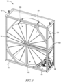
- An energy recovery system 10 in accordance with the present invention includes a support frame 12, an energy recovery wheel 14, and a wheel actuator 16 as shown in Fig. 1 .
- the support frame 12 is configured to support the wheel actuator 16 within an air handling unit (not shown).
- the support frame 12 may form a part of the air-handling unit or may be separate from the air-handling unit and coupled to the energy recovery wheel 14 such that the support frame 12, energy recovery wheel 14, and wheel actuator 16 form a removable subassembly within the air-handling unit.
- the air handling unit includes or defines an air-supply section 102 that supplies outdoor air into a building and an air-exhaust section 104 that removes indoor air from the building at the same time to ventilate the building with fresh, outdoor air.
- the indoor air and the outdoor air both pass through the energy recovery wheel 14 to exchange heat and/or moisture between the indoor air and the outdoor air.
- the energy recovery wheel 14 is driven in rotation by the wheel actuator 16 relative to the air handling unit and is arranged to lie in both the air-supply section and the air-return section to exchange heat and/or moisture between the indoor air and the outdoor air in order to reduce energy losses.
- the energy recovery wheel 14 rotates about a central rotational axis 15 relative to the support frame 12 so that portions of the energy recovery wheel 14 are continuously moved into and out of the air-supply section 102 and the air-return section 104 as the indoor and outdoor air flows therethrough.
- the energy recovery wheel 14 includes an outer shell 20 and an energy absorption media 22 arranged to lie within a perimeter of the outer shell 20.
- the outer shell 20 engages the wheel actuator 16 and is driven by the wheel actuator 16 to rotate the energy recovery wheel 14 about the central rotational axis 15 during operation of the energy recovery system 10.
- the expression "energy recovery wheel” should be interpreted to include, without limitation thereto, a rotary wheel, a thermal wheel, a sensible wheel, a heat wheel, a desiccant wheel, a dehumidification wheel, a heat and/or moisture recovery wheel, a total energy recovery wheel, a enthalpy wheel, a regeneratable rotary dehumidification wheel, a rotary enthalpy wheel, a rotating wheel exchanger and the like.
- the energy absorption media 22 may be corrugated or fluted sheets of material that absorbs heat and/or moisture from one of the indoor air and the outdoor air and releases the heat and/or moisture into the other of the indoor air and the outdoor air.
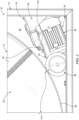
- the wheel actuator 16 is mounted to the support frame 12, or another portion of the air-handling unit, as shown in Figs. 1 and 2 .
- the wheel actuator 16 is located at a lower corner of the support frame 12 relative to the energy recovery wheel 14, however, in other embodiments the wheel actuator 16 may be located in another location relative to the energy recovery wheel 14.
- the wheel actuator 16 includes a motor 24 and a drive wheel 26 coupled to the motor 24.
- the motor 24 is configured to drive rotation of the drive wheel 26 about a wheel rotation axis 28.
- the drive wheel 26 directly engages the outer shell 20 of the energy recovery wheel 14 and drives the energy recovery wheel 14 to rotate about the central rotational axis 15 during operation.
- Some prior wheel actuators include a belt that wraps around the outer shell of the energy recovery wheel and that is driven by a drive wheel.
- the drive wheel is spaced apart from the outer shell and slots are formed in various seal members 106 separating the air-supply section 102 and the air-exhaust section 104 to provide clearance for the belt.
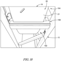
- the drive wheel 26 in the illustrated embodiment is placed in direct contact with the outer shell 20 so that the belt and the corresponding slots in the seal members 106 can be omitted thereby improving efficiency of the system 10 as shown in Fig. 10 .
- the seal member 106 interfaces with a radially-outer surface 21 of the outer shell 20 and extends generally parallel with the rotation axis 15 from a forward end of the outer shell 20 to a rear end of the outer shell 20.
- Each seal member 106 is formed without any slots opening toward the outer shell 20 between the forward end and the rear end.
- the motor 24 may include an induction motor, a permanent magnet synchronous motor (PMSM), a direct PMSM motor, a direct induction motor, or any other suitable type of motor.
- the motor 24 may be brushed or brushless.
- the motor 24 may be powered via direct current (DC) or alternating current (AC), or may be an electrically communicated (EC) motor, in some embodiments.
- the drive wheel 26 includes a wheel hub 30 and a peripheral skin 32 that circumscribes an outer surface of the wheel hub 30 as shown in Fig. 5 .
- the wheel hub 30 may be made from aluminum or any other suitable material and is solid to reduce inertia and energy consumption.
- the peripheral skin 32 may include polyurethane or another suitable material to increase friction between the drive wheel 26 and the outer shell 20.
- the peripheral skin 32 may have a flat outer surface or may be formed to include thread 34 to increase grip on the outer shell 20.
- the thread 34 is defined by a plurality of channels 36 formed into the peripheral skin 32.
- the plurality of channels 36 illustratively form a plurality of diamond-shaped pads 38, however, in other embodiments the plurality of channels 36 may define pads or structures having a different shape.
- the diamond-shaped pads 38 may reduce noise and heat and may increase durability of the peripheral skin compared to threads having pads with different shapes or no shape.
- the energy recovery system 10 further includes an actuator mount 18 configured to position and retain the wheel actuator 16 relative to the energy recovery wheel 16 as shown in Figs. 1-3 .
- the actuator mount 18 includes a stationary mount 40 and a motor mount 42 coupled to the wheel actuator 16.
- the stationary mount 40 is configured to couple to the support frame 12 in a fixed position relative to the energy recovery wheel 14.
- the motor mount 42 is coupled to the stationary mount 40 and is configured to pivot about an actuator pivot axis 44 to allow movement of the wheel actuator 16 relative to stationary mount 40. Pivoting of the motor mount 42 allows the wheel actuator 16 to move relative to the energy recovery wheel 14 or remain in contact with the energy recovery wheel 14.
- the stationary mount 40 is a part of the support frame 12 or a part of the air-handling unit.
- the actuator mount 18 further includes a tensioning system 50 configured to bias the motor mount 42 to pivot about the actuator pivot axis 44 in direction 110 so that the drive wheel 26 is biased into contact with the outer shell 20 of the energy recovery wheel 14 and applies a load 112 on the outer shell 20.
- the tensioning system 50 includes a pair of adjustable spring mounts 52 coupled to the motor mount 42 and a corresponding pair of biasing springs 54.
- Each of the biasing springs 54 extends between the motor mount 42 and a portion of the stationary mount 40, although in other embodiments, the biasing springs 54 may be coupled to a portion of the support frame 12 or another part of the air-handling unit.
- the biasing springs 54 are tension springs and are coupled to a first end 56 of the motor mount 42 to bias an opposite, second end 58 of the motor mount 42 toward the energy recovery wheel 14.
- the actuator pivot axis 44 is located between the first end 56 and the second end 58 to provide this motion.
- the illustrative embodiment includes two tension springs 54, it should be noted that any number of springs may be used to bias the second end 58 of the motor mount 42 and the drive wheel 26 toward the energy recovery wheel 14. In other embodiments, a different type of biasing element may be used in place of the tension springs 54 such as compression springs, torsion springs, leaf springs, hydraulics, elastic members, etc.
- Each biasing spring 54 is coupled to a corresponding adjustable spring mount 52 as shown in Fig. 1 and 9 .
- Each adjustable spring mount 52 is rotatable relative to the motor mount 42 to increase or decrease a spring force provided by the biasing springs 54 on the adjustable spring mount 52 and the first end 56 of the motor mount 42.
- Each adjustable spring mount 52 includes an eyelet 60 to which a respective biasing spring 54 is coupled and a threaded shaft 62 coupled to the first end 56 of the motor mount 42.
- a nut 64 threadingly engages with a respective threaded shaft 62 to retain each adjustable spring mount 52 to the motor mount 42.
- the threaded shaft 62 may threadingly engage with the motor mount 42 such that the retainer nut 64 can be omitted. Rotation of the nut 64 and/or the threaded shaft 62 of each adjustable spring mount increases or decreases a distance between the eyelet 60 and the motor mount 42 to increase or decrease the force provided by each spring 54 on each respective adjustable spring mount 52.
- the motor mount 42 includes a mount plate 70 supporting the wheel actuator 24, a mount bracket 72 coupled to the mount plate 70, and a pair of mount rods 74, 76 coupled to the mount bracket 72 and extending outwardly from the mount plate 70.
- the mount rods 74, 76 are arranged along the actuator pivot axis 44 and set within u-shaped channels 78, 80 formed in the stationary mount 40 to support the motor mount 42 on the stationary mount 40.
- the motor mount 42 may further include a vibration-dampening bushing 82, 84 coupled to each mount rod 74, 76.
- Each vibration-dampening bushing 82, 84 is at least partially received within a corresponding channel 78, 80 to lie between a corresponding mount rod 74, 76 and the stationary mount 40 to dampen vibrations produced by the wheel actuator 16 during operation.
- the stationary mount 40 includes a pair of side brackets 90, 92, a base crossbeam 94, and a motor-mount support 96 as shown in Fig. 4 .
- the pair of side brackets 90, 92 are spaced apart from one another by a distance that corresponds with a width of the support frame 12 so that each side bracket 90, 92 can be attached to corresponding frame members 98, 100 of the support frame 12 as shown in Fig. 1 .
- the base crossbeam 94 extends between the side brackets 90, 92 and is formed to include apertures 95 that can be used to attach an end of each biasing spring 54.
- the motor-mount support 96 also extends between the side brackets 90, 92 and is configured to position the motor mount 42 and the wheel actuator 16 adjacent to the energy recovery wheel 14.
- the u-shaped channels 78, 80 are formed in the motor-mount support 96 and open upwardly so that the mount rods 74, 76 can be lowered into each corresponding channel 78, 80 during installation as suggested in Figs. 6-9 .
- the biasing springs 54 can be attached to each adjustable spring mount 52 and the base crossbeam 94 via apertures 95.
- the motor mount support includes an upper crossbeam 102 located above the motor mount 42 to block over-rotation of the motor mount 42 during installation.
- the mount rods 74, 76 are held by gravity in each u-shaped channel 78, 80, but tension provided by the biasing springs 54 also helps retain the mount rods 74, 76 in the u-shaped channels 78, 80.
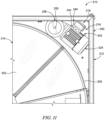
- FIG. 11 Another embodiment of an energy recovery system 210 is shown in Fig. 11 .
- the energy recovery system 210 is substantially similar to energy recovery system 10 and includes a support frame 212, an energy recovery wheel 214, and a wheel actuator 216. Similar reference numbers in the 200 series are used to describe similar features between energy recovery system 210 and energy recovery system 10. Accordingly, the disclosure of energy recovery system 10 is incorporated by reference for energy recovery system 210.
- the wheel actuator 216 includes a motor 224 and a drive wheel 226 coupled to the motor 224.
- the motor 224 is configured to drive rotation of the drive wheel 226 about a wheel rotation axis 228.
- the drive wheel 226 directly engages the outer shell 220 of the energy recovery wheel 214 and drives the energy recovery wheel 214 to rotate about a central rotational axis during operation.
- the energy recovery system 210 further includes an actuator mount 218 configured to position and retain the wheel actuator 216 relative to the energy recovery wheel 214 as shown in Fig. 11 .
- the actuator mount 218 includes a stationary mount 240, a motor mount 242 coupled to the wheel actuator 216, and a tensioning system 250.
- the stationary mount 240 is coupled to the support frame 212 in a fixed position relative to the energy recovery wheel 214.
- the stationary mount 240 is located in an upper half of the support frame 212 to use gravity to at least partially bias the wheel actuator 216 into contact with the energy recovery wheel 214.
- the motor mount 242 is coupled to the stationary mount 240 and is configured to pivot about an actuator pivot axis 244 to allow movement of the wheel actuator 216 relative to the energy recovery wheel 214 while supporting the wheel actuator 216 relative to the energy recovery wheel 214.
- the stationary mount 240 is a part of the support frame 212 or a part of the air-handling unit.
- the tensioning system 250 is optional but, if included, is configured to bias the motor mount 242 to pivot about the actuator pivot axis 244 so that the drive wheel 226 is biased into contact with the outer shell 220 of the energy recovery wheel 214.
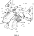
- FIG. 12 and 13 Another embodiment of a wheel actuator 316 and an actuator mount 318 that can be used with energy recovery system 10, 210 is shown in Figs. 12 and 13 .
- the wheel actuator 316 and the actuator mount 318 are substantially similar to wheel actuator 16 and actuator mount 18, respectively. Similar reference numbers in the 300 series are used to describe similar features between wheel actuator 316 and actuator mount 318 and wheel actuator 16 and actuator mount 18, respectively. Accordingly, the disclosure of wheel actuator 16 and actuator mount 18 is incorporated by reference for wheel actuator 316 and actuator mount 318.
- the wheel actuator 316 includes a motor 324 and a drive wheel 326 coupled to the motor 324.
- the motor 324 is configured to drive rotation of the drive wheel 326 about a wheel rotation axis 328.
- the drive wheel 326 directly engages the outer shell 20 of the energy recovery wheel 14 and drives the energy recovery wheel 14 to rotate about the central rotational axis 15 during operation.
- the actuator mount 318 is configured to position and retain the wheel actuator 316 relative to the energy recovery wheel 14.
- the actuator mount 318 includes a stationary mount 340, a motor mount 342 coupled to the wheel actuator 316, and a tensioning system 350.
- the stationary mount 340 is coupled to the support frame 12 in a fixed position relative to the energy recovery wheel 14.
- the tensioning system 350 includes a pair of adjustable spring mounts 352 coupled to the motor mount 342 and a corresponding pair of biasing springs 354.
- Each of the biasing springs 354 extends between the motor mount 342 and a portion of the stationary mount 340, although in other embodiments, the biasing springs 354 may be coupled to a portion of the support frame 12 or another part of the air-handling unit.
- Each biasing spring 354 is coupled to a corresponding adjustable spring mount 352.
- Each adjustable spring mount 352 is rotatable relative to the motor mount 342 to increase or decrease a spring force provided by the biasing springs 354 on the adjustable spring mount 354 and the motor mount 342.
- the motor mount 342 includes a mount plate 370 supporting the wheel actuator 324, a pair of mount flanges 372, 373 coupled to the mount plate 370, and a mount rod 374.
- the pair of mount flanges 372, 373 are coupled to opposite lateral sides of the mount plate 370 and extend upwardly away from the mount plate 370.
- Each mount flange 372, 373 is formed to include a mount aperture 379, 381.
- the mount rod 374 is arranged along the actuator pivot axis 344 and received within apertures 378, 380 formed in the stationary mount 340 and apertures 379, 381 formed in mount flanges 372, 373 to support the motor mount 342 on the stationary mount 340.
- the motor mount 342 may further include a vibration-dampening bushing 382, 384 coupled to at least one of the mount rod 374, the mount flanges 372, 373, and/or the stationary mount 340.
- Each vibration-dampening bushing 382, 384 may be at least partially received within a corresponding aperture 378, 380 to lie between the mount rod 374 and the stationary mount 340 to dampen vibrations produced by the wheel actuator 316 during operation.
- Vibration-dampening bushings 382, 384 may also be arranged to lie in apertures 379, 381 to lie between the mount flanges 372, 373 and the mount rod 374.
- the mount rod 374 has a length that is greater than a distance between apertures 378, 380 so that the mount rod extends past each aperture 378, 380.
Landscapes
- Engineering & Computer Science (AREA)
- Chemical & Material Sciences (AREA)
- Combustion & Propulsion (AREA)
- Mechanical Engineering (AREA)
- General Engineering & Computer Science (AREA)
- Connection Of Motors, Electrical Generators, Mechanical Devices, And The Like (AREA)
- Handcart (AREA)
- Vibration Prevention Devices (AREA)
- Arrangement Or Mounting Of Propulsion Units For Vehicles (AREA)
- Motorcycle And Bicycle Frame (AREA)
Description
- The present invention relates to an energy recovery system, and particularly to an energy recovery system for an air handling unit. More particularly, the present disclosure relates to an energy recovery system that includes an energy recovery wheel that is driven in rotation about an axis to exchange energy between airflows.
-
US 5 183 098 A discloses an energy recovery system having the features of the preamble of independent claim 1. - In accordance with the present invention, an energy recovery system for an air handling unit includes an energy recovery wheel configured to rotate about a first axis, a motor, and a drive wheel coupled to the motor for rotation about a second axis that is offset from the first axis and the energy recovery wheel and having an outer surface engaged directly with an outer surface of the energy recovery wheel. The energy recovery system further includes an actuator mount configured to support the motor relative to the energy recovery wheel, the actuator mount including a motor mount coupled to the motor and a stationary mount coupled to the air handling unit in a fixed position and configured to support the motor mount for pivotable movement about an actuator pivot axis so that the drive wheel is pivotable into contact with the outer surface of the energy recovery wheel.
- In some embodiments, the energy recovery system further includes a tensioning system configured to bias the motor to pivot about the actuator pivot axis to urge the drive wheel into contact with the outer surface of the energy recovery wheel. In some embodiments, the tensioning system includes an adjustable spring mount coupled to the motor and a biasing spring coupled to the adjustable spring mount. In some embodiments, the biasing spring is coupled to a first end of the motor mount to bias an opposite, second end of the motor mount toward the energy recovery wheel, the drive wheel being coupled to the motor at the second end of the motor mount. In some embodiments, the biasing spring is coupled to an end of the spring mount spaced apart from the motor mount at the first end to bias the second end of the motor mount toward the energy recovery wheel. In some embodiments, the adjustable spring mount is adjustable, in particular rotatable relative to the motor to increase or decrease a spring force provided by the biasing spring on the adjustable spring mount.
- In some embodiments, the motor mount includes a mount plate supporting the motor, a pair of mount flanges coupled to the mount plate, and a mount rod coupled to the mount flanges and providing the actuator pivot axis.
- In some embodiments, the energy recovery system further includes a vibration dampening bushing coupled to the mount rod and arranged to lie between the mount rod and at least one of the stationary mount and the mount plate to dampen vibrations therebetween.
- In some embodiments, motor mount comprises a pair of flanges including a first mount flange formed to include a first flange aperture, a second mount flange spaced apart from the first mount flange along the actuator pivot axis and formed to include a second flange aperture, and a mount rod received within the first mount flange and the second mount flange, and at least one stationary-mount aperture formed in the stationary mount to couple the motor mount and the wheel actuator to the stationary mount. In some embodiments, the energy recovery system further includes a first vibration dampening bushing arranged to lie between the mount rod and the first mount flange and a second vibration dampening bushing arranged to lie between the mount rod and the second mount flange.
- Additional features of the present invention will become apparent to those skilled in the art upon consideration of illustrative embodiments exemplifying the best mode of carrying out the invention as presently perceived.
- The detailed description particularly refers to the accompanying figures in which:
-
Fig. 1 is a perspective view of an exemplary energy recovery system for an air handling unit, the energy recovery system including an energy recovery wheel and a wheel actuator configured to rotate the energy recovery wheel about a rotation axis; -
Fig. 2 is a perspective view of a portion of the energy recovery system ofFig. 1 showing the wheel actuator engaged directly with the energy recovery wheel; -
Fig. 3 is a side elevation view of the energy recovery system ofFig. 1 showing that the wheel actuator has a motor and a drive wheel that is biased into engagement with the energy recovery wheel; -
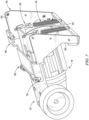
Fig. 4 is a perspective view of the wheel actuator fromFigs. 1-3 ; -
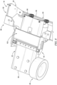
Fig. 5 is an enlarged perspective view of the drive wheel of the wheel actuator ofFig. 1 ; -
Fig. 6 is a side elevation view of the wheel actuator ofFig. 1 separated from a stationary actuator mount used to mount the motor and the drive wheel relative to the energy recovery wheel during an installation process; -
Fig. 7 is a perspective view of the wheel actuator ofFig. 1 showing a pair of mount rods coupled to the motor positioned above a pair of corresponding U-shaped channels formed in the stationary actuator mount; -
Fig. 8 is a perspective view of the wheel actuator ofFig. 1 showing the mount rods lowered into the corresponding U-shaped channels; -
Fig. 9 is a perspective view of the wheel actuator ofFig. 1 showing a tensioning system including a pair of tension springs that apply a tensile force on the motor to bias the drive wheel into engagement with the energy recovery wheel; -
Fig. 10 is a side perspective view of the energy recovery system fromFig. 1 showing an interface between a seal member and the energy recovery wheel; -
Fig. 11 is a side elevation of another energy recovery assembly including an energy recovery wheel and a second embodiment of a wheel actuator having a motor and a drive wheel that is biased, at least partially, by gravity into direct engagement with the energy recovery wheel and configured to drive the energy recovery wheel to rotate about a rotation axis; -
Fig. 12 is a perspective view of a third embodiment of a wheel actuator that can be used with the energy recovery system ofFig. 1 ; and -
Fig. 13 is an exploded assembly view of the wheel actuator shown inFig. 12 . - An
energy recovery system 10 in accordance with the present invention, includes asupport frame 12, anenergy recovery wheel 14, and awheel actuator 16 as shown inFig. 1 . Thesupport frame 12 is configured to support thewheel actuator 16 within an air handling unit (not shown). Thesupport frame 12 may form a part of the air-handling unit or may be separate from the air-handling unit and coupled to theenergy recovery wheel 14 such that thesupport frame 12,energy recovery wheel 14, andwheel actuator 16 form a removable subassembly within the air-handling unit. The air handling unit includes or defines an air-supply section 102 that supplies outdoor air into a building and an air-exhaust section 104 that removes indoor air from the building at the same time to ventilate the building with fresh, outdoor air. The indoor air and the outdoor air both pass through theenergy recovery wheel 14 to exchange heat and/or moisture between the indoor air and the outdoor air. Theenergy recovery wheel 14 is driven in rotation by thewheel actuator 16 relative to the air handling unit and is arranged to lie in both the air-supply section and the air-return section to exchange heat and/or moisture between the indoor air and the outdoor air in order to reduce energy losses. - The
energy recovery wheel 14 rotates about a centralrotational axis 15 relative to thesupport frame 12 so that portions of theenergy recovery wheel 14 are continuously moved into and out of the air-supply section 102 and the air-return section 104 as the indoor and outdoor air flows therethrough. Theenergy recovery wheel 14 includes anouter shell 20 and anenergy absorption media 22 arranged to lie within a perimeter of theouter shell 20. Theouter shell 20 engages thewheel actuator 16 and is driven by thewheel actuator 16 to rotate theenergy recovery wheel 14 about the centralrotational axis 15 during operation of theenergy recovery system 10. The expression "energy recovery wheel" should be interpreted to include, without limitation thereto, a rotary wheel, a thermal wheel, a sensible wheel, a heat wheel, a desiccant wheel, a dehumidification wheel, a heat and/or moisture recovery wheel, a total energy recovery wheel, a enthalpy wheel, a regeneratable rotary dehumidification wheel, a rotary enthalpy wheel, a rotating wheel exchanger and the like. Theenergy absorption media 22 may be corrugated or fluted sheets of material that absorbs heat and/or moisture from one of the indoor air and the outdoor air and releases the heat and/or moisture into the other of the indoor air and the outdoor air. - The
wheel actuator 16 is mounted to thesupport frame 12, or another portion of the air-handling unit, as shown inFigs. 1 and2 . In the illustrative embodiment, thewheel actuator 16 is located at a lower corner of thesupport frame 12 relative to theenergy recovery wheel 14, however, in other embodiments thewheel actuator 16 may be located in another location relative to theenergy recovery wheel 14. Thewheel actuator 16 includes amotor 24 and adrive wheel 26 coupled to themotor 24. Themotor 24 is configured to drive rotation of thedrive wheel 26 about awheel rotation axis 28. Thedrive wheel 26 directly engages theouter shell 20 of theenergy recovery wheel 14 and drives theenergy recovery wheel 14 to rotate about the centralrotational axis 15 during operation. - Some prior wheel actuators include a belt that wraps around the outer shell of the energy recovery wheel and that is driven by a drive wheel. However, in this instance the drive wheel is spaced apart from the outer shell and slots are formed in
various seal members 106 separating the air-supply section 102 and the air-exhaust section 104 to provide clearance for the belt. Unlike systems using those prior wheel actuators, thedrive wheel 26 in the illustrated embodiment is placed in direct contact with theouter shell 20 so that the belt and the corresponding slots in theseal members 106 can be omitted thereby improving efficiency of thesystem 10 as shown inFig. 10 . Theseal member 106 interfaces with a radially-outer surface 21 of theouter shell 20 and extends generally parallel with therotation axis 15 from a forward end of theouter shell 20 to a rear end of theouter shell 20. Eachseal member 106 is formed without any slots opening toward theouter shell 20 between the forward end and the rear end. - The
motor 24 may include an induction motor, a permanent magnet synchronous motor (PMSM), a direct PMSM motor, a direct induction motor, or any other suitable type of motor. Themotor 24 may be brushed or brushless. Themotor 24 may be powered via direct current (DC) or alternating current (AC), or may be an electrically communicated (EC) motor, in some embodiments. - The
drive wheel 26 includes awheel hub 30 and aperipheral skin 32 that circumscribes an outer surface of thewheel hub 30 as shown inFig. 5 . Thewheel hub 30 may be made from aluminum or any other suitable material and is solid to reduce inertia and energy consumption. Theperipheral skin 32 may include polyurethane or another suitable material to increase friction between thedrive wheel 26 and theouter shell 20. Theperipheral skin 32 may have a flat outer surface or may be formed to includethread 34 to increase grip on theouter shell 20. Thethread 34 is defined by a plurality ofchannels 36 formed into theperipheral skin 32. The plurality ofchannels 36 illustratively form a plurality of diamond-shaped pads 38, however, in other embodiments the plurality ofchannels 36 may define pads or structures having a different shape. The diamond-shaped pads 38 may reduce noise and heat and may increase durability of the peripheral skin compared to threads having pads with different shapes or no shape. - The
energy recovery system 10 further includes anactuator mount 18 configured to position and retain thewheel actuator 16 relative to theenergy recovery wheel 16 as shown inFigs. 1-3 . Theactuator mount 18 includes astationary mount 40 and amotor mount 42 coupled to thewheel actuator 16. Thestationary mount 40 is configured to couple to thesupport frame 12 in a fixed position relative to theenergy recovery wheel 14. Themotor mount 42 is coupled to thestationary mount 40 and is configured to pivot about anactuator pivot axis 44 to allow movement of thewheel actuator 16 relative tostationary mount 40. Pivoting of themotor mount 42 allows thewheel actuator 16 to move relative to theenergy recovery wheel 14 or remain in contact with theenergy recovery wheel 14. In some embodiments, thestationary mount 40 is a part of thesupport frame 12 or a part of the air-handling unit. - The
actuator mount 18 further includes atensioning system 50 configured to bias themotor mount 42 to pivot about theactuator pivot axis 44 indirection 110 so that thedrive wheel 26 is biased into contact with theouter shell 20 of theenergy recovery wheel 14 and applies aload 112 on theouter shell 20. Thetensioning system 50 includes a pair of adjustable spring mounts 52 coupled to themotor mount 42 and a corresponding pair of biasing springs 54. Each of the biasing springs 54 extends between themotor mount 42 and a portion of thestationary mount 40, although in other embodiments, the biasing springs 54 may be coupled to a portion of thesupport frame 12 or another part of the air-handling unit. Illustratively, the biasing springs 54 are tension springs and are coupled to afirst end 56 of themotor mount 42 to bias an opposite,second end 58 of themotor mount 42 toward theenergy recovery wheel 14. Theactuator pivot axis 44 is located between thefirst end 56 and thesecond end 58 to provide this motion. - Although the illustrative embodiment includes two tension springs 54, it should be noted that any number of springs may be used to bias the
second end 58 of themotor mount 42 and thedrive wheel 26 toward theenergy recovery wheel 14. In other embodiments, a different type of biasing element may be used in place of the tension springs 54 such as compression springs, torsion springs, leaf springs, hydraulics, elastic members, etc. - Each biasing
spring 54 is coupled to a correspondingadjustable spring mount 52 as shown inFig. 1 and9 . Eachadjustable spring mount 52 is rotatable relative to themotor mount 42 to increase or decrease a spring force provided by the biasing springs 54 on theadjustable spring mount 52 and thefirst end 56 of themotor mount 42. Eachadjustable spring mount 52 includes aneyelet 60 to which arespective biasing spring 54 is coupled and a threadedshaft 62 coupled to thefirst end 56 of themotor mount 42. Anut 64 threadingly engages with a respective threadedshaft 62 to retain eachadjustable spring mount 52 to themotor mount 42. The threadedshaft 62 may threadingly engage with themotor mount 42 such that theretainer nut 64 can be omitted. Rotation of thenut 64 and/or the threadedshaft 62 of each adjustable spring mount increases or decreases a distance between theeyelet 60 and themotor mount 42 to increase or decrease the force provided by eachspring 54 on each respectiveadjustable spring mount 52. - The
motor mount 42 includes amount plate 70 supporting thewheel actuator 24, amount bracket 72 coupled to themount plate 70, and a pair ofmount rods mount bracket 72 and extending outwardly from themount plate 70. Themount rods actuator pivot axis 44 and set withinu-shaped channels stationary mount 40 to support themotor mount 42 on thestationary mount 40. - The
motor mount 42 may further include a vibration-dampeningbushing mount rod bushing channel corresponding mount rod stationary mount 40 to dampen vibrations produced by thewheel actuator 16 during operation. - The
stationary mount 40 includes a pair ofside brackets base crossbeam 94, and a motor-mount support 96 as shown inFig. 4 . The pair ofside brackets support frame 12 so that eachside bracket frame members support frame 12 as shown inFig. 1 . Thebase crossbeam 94 extends between theside brackets apertures 95 that can be used to attach an end of each biasingspring 54. The motor-mount support 96 also extends between theside brackets motor mount 42 and thewheel actuator 16 adjacent to theenergy recovery wheel 14. - The
u-shaped channels mount support 96 and open upwardly so that themount rods channel Figs. 6-9 . Once themount rods u-shaped channels adjustable spring mount 52 and thebase crossbeam 94 viaapertures 95. The motor mount support includes anupper crossbeam 102 located above themotor mount 42 to block over-rotation of themotor mount 42 during installation. Themount rods u-shaped channel mount rods u-shaped channels - Another embodiment of an
energy recovery system 210 is shown inFig. 11 . Theenergy recovery system 210 is substantially similar toenergy recovery system 10 and includes asupport frame 212, anenergy recovery wheel 214, and awheel actuator 216. Similar reference numbers in the 200 series are used to describe similar features betweenenergy recovery system 210 andenergy recovery system 10. Accordingly, the disclosure ofenergy recovery system 10 is incorporated by reference forenergy recovery system 210. - The
wheel actuator 216 includes amotor 224 and adrive wheel 226 coupled to themotor 224. Themotor 224 is configured to drive rotation of thedrive wheel 226 about awheel rotation axis 228. Thedrive wheel 226 directly engages theouter shell 220 of theenergy recovery wheel 214 and drives theenergy recovery wheel 214 to rotate about a central rotational axis during operation. - The
energy recovery system 210 further includes anactuator mount 218 configured to position and retain thewheel actuator 216 relative to theenergy recovery wheel 214 as shown inFig. 11 . Theactuator mount 218 includes astationary mount 240, amotor mount 242 coupled to thewheel actuator 216, and atensioning system 250. Thestationary mount 240 is coupled to thesupport frame 212 in a fixed position relative to theenergy recovery wheel 214. Thestationary mount 240 is located in an upper half of thesupport frame 212 to use gravity to at least partially bias thewheel actuator 216 into contact with theenergy recovery wheel 214. Themotor mount 242 is coupled to thestationary mount 240 and is configured to pivot about anactuator pivot axis 244 to allow movement of thewheel actuator 216 relative to theenergy recovery wheel 214 while supporting thewheel actuator 216 relative to theenergy recovery wheel 214. In some embodiments, thestationary mount 240 is a part of thesupport frame 212 or a part of the air-handling unit. Thetensioning system 250 is optional but, if included, is configured to bias themotor mount 242 to pivot about theactuator pivot axis 244 so that thedrive wheel 226 is biased into contact with theouter shell 220 of theenergy recovery wheel 214. - Another embodiment of a
wheel actuator 316 and anactuator mount 318 that can be used withenergy recovery system Figs. 12 and13 . Thewheel actuator 316 and theactuator mount 318 are substantially similar towheel actuator 16 andactuator mount 18, respectively. Similar reference numbers in the 300 series are used to describe similar features betweenwheel actuator 316 andactuator mount 318 andwheel actuator 16 andactuator mount 18, respectively. Accordingly, the disclosure ofwheel actuator 16 andactuator mount 18 is incorporated by reference forwheel actuator 316 andactuator mount 318. - The
wheel actuator 316 includes amotor 324 and adrive wheel 326 coupled to themotor 324. Themotor 324 is configured to drive rotation of thedrive wheel 326 about awheel rotation axis 328. Thedrive wheel 326 directly engages theouter shell 20 of theenergy recovery wheel 14 and drives theenergy recovery wheel 14 to rotate about the centralrotational axis 15 during operation. - The
actuator mount 318 is configured to position and retain thewheel actuator 316 relative to theenergy recovery wheel 14. Theactuator mount 318 includes astationary mount 340, amotor mount 342 coupled to thewheel actuator 316, and atensioning system 350. Thestationary mount 340 is coupled to thesupport frame 12 in a fixed position relative to theenergy recovery wheel 14. - The
tensioning system 350 includes a pair of adjustable spring mounts 352 coupled to themotor mount 342 and a corresponding pair of biasing springs 354. Each of the biasing springs 354 extends between themotor mount 342 and a portion of thestationary mount 340, although in other embodiments, the biasing springs 354 may be coupled to a portion of thesupport frame 12 or another part of the air-handling unit. Each biasingspring 354 is coupled to a correspondingadjustable spring mount 352. Eachadjustable spring mount 352 is rotatable relative to themotor mount 342 to increase or decrease a spring force provided by the biasing springs 354 on theadjustable spring mount 354 and themotor mount 342. - The
motor mount 342 includes amount plate 370 supporting thewheel actuator 324, a pair ofmount flanges mount plate 370, and amount rod 374. The pair ofmount flanges mount plate 370 and extend upwardly away from themount plate 370. Eachmount flange mount aperture mount rod 374 is arranged along theactuator pivot axis 344 and received withinapertures stationary mount 340 andapertures mount flanges motor mount 342 on thestationary mount 340. - The
motor mount 342 may further include a vibration-dampeningbushing mount rod 374, themount flanges stationary mount 340. Each vibration-dampeningbushing aperture mount rod 374 and thestationary mount 340 to dampen vibrations produced by thewheel actuator 316 during operation. Vibration-dampeningbushings apertures mount flanges mount rod 374. Themount rod 374 has a length that is greater than a distance betweenapertures aperture
Claims (10)
- An energy recovery system (10, 210) for an air handling unit comprising:an energy recovery wheel (14, 214) configured to rotate about a first axis (15),a motor (24, 224, 324), anda drive wheel (26, 226, 326) coupled to the motor (24, 224, 324) for rotation about a second axis (28, 228, 328) that is offset from the first axis (15) and the energy recovery wheel (14, 214) and having an outer surface engaged directly with an outer surface (21) of the energy recovery wheel (14, 214),characterized byan actuator mount (18, 218, 318) configured to support the motor (24, 224, 324) relative to the energy recovery wheel (14, 214), the actuator mount (18, 218, 318) including a motor mount (42, 242, 342) coupled to the motor (24, 224, 324) and a stationary mount (40, 240, 340) coupled to the air handling unit in a fixed position and configured to support the motor mount (42, 242, 342) for pivotable movement about an actuator pivot axis (44, 244, 344) so that the drive wheel (26, 226, 326) is pivotable into contact with the outer surface (21) of the energy recovery wheel (14, 214).
- The energy recovery system (10, 210) of claim 1, further comprising a tensioning system (50, 250, 350) configured to bias the motor (24, 224, 324) to pivot about the actuator pivot axis (44, 244, 344) to urge the drive wheel (26, 226, 326) into contact with the outer surface (21) of the energy recovery wheel (14, 214).
- The energy recovery system (10, 210) of claim 2, wherein the tensioning system (50, 250, 350) includes an adjustable spring mount (52, 352) coupled to the motor (24, 224, 324) and a biasing spring (54, 354) coupled to the adjustable spring mount (52, 352).
- The energy recovery system (10, 210) of claim 3, wherein the biasing spring (54, 354) is coupled to a first end (56) of the motor mount (42, 242, 342) to bias an opposite, second end (58) of the motor mount (42, 242, 342) toward the energy recovery wheel (14, 214), the drive wheel (26, 226, 326) being coupled to the motor (24, 224, 324) at the second end (58) of the motor mount (42, 242, 342).
- The energy recovery system (10, 210) of claim 4, wherein the biasing spring (54, 354) is coupled to an end of the spring mount (42, 242, 342) spaced apart from the motor mount (42, 242, 342) at the first end (56) to bias the second end (58) of the motor mount (42, 242, 342) toward the energy recovery wheel (14, 214).
- The energy recovery system of claim 5, wherein the adjustable spring mount (52, 352) is rotatable relative to the motor mount (42, 242, 342) to increase or decrease a spring force provided by the biasing spring (54, 354) on the adjustable spring mount (52, 352).
- The energy recovery system (10, 210) of claim 1, wherein the motor mount (42, 242, 342) includes a mount plate (70, 370) supporting the motor (24, 224, 324), a pair of mount flanges (372, 373) coupled to the mount plate (70, 370), and a mount rod (374) coupled to the mount flanges (372, 373) and providing the actuator pivot axis (344).
- The energy recovery system (10, 210) of claim 7, further comprising a vibration dampening bushing (382, 384) coupled to the mount rod (374) and arranged to lie between the mount rod (374) and at least one of the stationary mount (340) and the mount plate (70, 370) to dampen vibrations therebetween.
- The energy recovery system (10, 210) of claim 7, wherein the pair of mount flanges (372, 373) includes a first mount flange (372) formed to include a first flange aperture (379), a second mount flange (373) spaced apart from the first mount flange (372) along the actuator pivot axis (344) and formed to include a second flange aperture (381), the mount rod (374) received within the first mount flange (372), the second mount flange (373), and at least one stationary-mount aperture (378, 380) formed in the stationary mount (40, 240, 340) to couple the motor mount (42, 242, 342) and the motor (24, 224, 324) to the stationary mount (40, 240, 340).
- The energy recovery system (10, 210) of claim 9, further comprising a first vibration dampening bushing (382) arranged to lie between the mount rod (374) and the first mount flange (372) and a second vibration dampening bushing (384) arranged to lie between the mount rod (374) and the second mount flange (373).
Applications Claiming Priority (2)
| Application Number | Priority Date | Filing Date | Title |
|---|---|---|---|
| US202163175391P | 2021-04-15 | 2021-04-15 | |
| US17/675,572 US11619417B2 (en) | 2021-04-15 | 2022-02-18 | Contact wheel drive |
Publications (3)
| Publication Number | Publication Date |
|---|---|
| EP4102144A2 EP4102144A2 (en) | 2022-12-14 |
| EP4102144A3 EP4102144A3 (en) | 2023-01-11 |
| EP4102144B1 true EP4102144B1 (en) | 2025-03-12 |
Family
ID=81326453
Family Applications (1)
| Application Number | Title | Priority Date | Filing Date |
|---|---|---|---|
| EP22166879.1A Active EP4102144B1 (en) | 2021-04-15 | 2022-04-06 | Contact wheel drive |
Country Status (4)
| Country | Link |
|---|---|
| US (1) | US11619417B2 (en) |
| EP (1) | EP4102144B1 (en) |
| CA (1) | CA3150883C (en) |
| ES (1) | ES3027765T3 (en) |
Family Cites Families (10)
| Publication number | Priority date | Publication date | Assignee | Title |
|---|---|---|---|---|
| US4188993A (en) | 1977-06-09 | 1980-02-19 | Thermal Transfer Division of Kleinewefers | Heat recovery systems |
| US4589892A (en) * | 1983-04-07 | 1986-05-20 | Bry-Air, Inc. | Sequenced modular bed carousel dehumidifier |
| US5183098A (en) | 1989-08-17 | 1993-02-02 | Stirling Technology, Inc. | Air to air heat recovery ventilator |
| JP3152609B2 (en) | 1996-02-26 | 2001-04-03 | 三洋電機株式会社 | Dehumidifying and drying equipment |
| JP3222778B2 (en) | 1996-08-22 | 2001-10-29 | シャープ株式会社 | Humidifier |
| US5937667A (en) * | 1997-04-24 | 1999-08-17 | Advanced Thermal Technologies, Llc | System for the dehumidification of cooled air |
| US6422299B1 (en) | 2001-11-06 | 2002-07-23 | Thermotech Enterprises, Inc. | Wheel system for an air handling unit |
| WO2005103576A2 (en) * | 2004-04-22 | 2005-11-03 | Stirling Technology, Inc. | Heat and energy recovery ventilators and methods of use |
| JP5701738B2 (en) | 2011-12-20 | 2015-04-15 | ダイキン工業株式会社 | Humidifier |
| US9353868B2 (en) | 2011-12-22 | 2016-05-31 | Innergy Tech Inc. | Seal for energy recovery wheels having spaced apart lateral walls |
-
2022
- 2022-02-18 US US17/675,572 patent/US11619417B2/en active Active
- 2022-03-03 CA CA3150883A patent/CA3150883C/en active Active
- 2022-04-06 EP EP22166879.1A patent/EP4102144B1/en active Active
- 2022-04-06 ES ES22166879T patent/ES3027765T3/en active Active
Also Published As
| Publication number | Publication date |
|---|---|
| EP4102144A2 (en) | 2022-12-14 |
| CA3150883C (en) | 2023-11-21 |
| CA3150883A1 (en) | 2022-10-15 |
| US20220333812A1 (en) | 2022-10-20 |
| US11619417B2 (en) | 2023-04-04 |
| ES3027765T3 (en) | 2025-06-17 |
| EP4102144A3 (en) | 2023-01-11 |
Similar Documents
| Publication | Publication Date | Title |
|---|---|---|
| US6039109A (en) | Air to air heat and moisture recovery ventilator | |
| CN1135789A (en) | Rotatably supported regenerative fluid treatment wheel assembies | |
| KR102620428B1 (en) | Dehumidification rotor | |
| CN213846032U (en) | A constant temperature and humidity control cabinet | |
| EP1046012B1 (en) | Rotary heat exchange wheel | |
| EP4102144A2 (en) | Contact wheel drive | |
| JP7566169B2 (en) | Air conditioning equipment | |
| JP3154925U (en) | Desiccant rotor | |
| PL185289B1 (en) | Recuperative heat exchanger | |
| CN120760515B (en) | Energy-saving plate heat exchanger for ship | |
| JP5945685B2 (en) | Air conditioner | |
| JP4682667B2 (en) | Humidity control device | |
| CN219096443U (en) | Warm air system installation assembly | |
| CN222776034U (en) | Motor bracket for air conditioner, air conditioner | |
| CN113659238B (en) | A lightweight new energy battery cooling device | |
| SE2350815A1 (en) | A connection arrangement for attaching a rotor, and a dehumidifier comprising such a connection arrangement | |
| CN215398080U (en) | Vehicle-mounted air conditioner radiator convenient to assemble and disassemble | |
| CN217274545U (en) | A outer machine of mounting structure and air conditioner for air condensing units | |
| CN214333028U (en) | Movable louver support convenient to be connected with louvers | |
| CN217761812U (en) | New construction carbon pottery brake disc, wheel and vehicle | |
| KR102865820B1 (en) | Dehumidifying rotor | |
| CN121229429A (en) | A DC brushless fan with ventilation and heat dissipation structure | |
| CN221443328U (en) | Fireproof valve | |
| KR200278507Y1 (en) | Cooling-fan assembly structure of condensor-assembly for vehicle | |
| CN114961962A (en) | Fan fan protecting cover and control method thereof |
Legal Events
| Date | Code | Title | Description |
|---|---|---|---|
| PUAI | Public reference made under article 153(3) epc to a published international application that has entered the european phase |
Free format text: ORIGINAL CODE: 0009012 |
|
| STAA | Information on the status of an ep patent application or granted ep patent |
Free format text: STATUS: THE APPLICATION HAS BEEN PUBLISHED |
|
| PUAL | Search report despatched |
Free format text: ORIGINAL CODE: 0009013 |
|
| AK | Designated contracting states |
Kind code of ref document: A2 Designated state(s): AL AT BE BG CH CY CZ DE DK EE ES FI FR GB GR HR HU IE IS IT LI LT LU LV MC MK MT NL NO PL PT RO RS SE SI SK SM TR |
|
| AK | Designated contracting states |
Kind code of ref document: A3 Designated state(s): AL AT BE BG CH CY CZ DE DK EE ES FI FR GB GR HR HU IE IS IT LI LT LU LV MC MK MT NL NO PL PT RO RS SE SI SK SM TR |
|
| RIC1 | Information provided on ipc code assigned before grant |
Ipc: F24F 12/00 20060101ALI20221202BHEP Ipc: F24F 3/14 20060101AFI20221202BHEP |
|
| STAA | Information on the status of an ep patent application or granted ep patent |
Free format text: STATUS: REQUEST FOR EXAMINATION WAS MADE |
|
| 17P | Request for examination filed |
Effective date: 20230215 |
|
| RBV | Designated contracting states (corrected) |
Designated state(s): AL AT BE BG CH CY CZ DE DK EE ES FI FR GB GR HR HU IE IS IT LI LT LU LV MC MK MT NL NO PL PT RO RS SE SI SK SM TR |
|
| GRAP | Despatch of communication of intention to grant a patent |
Free format text: ORIGINAL CODE: EPIDOSNIGR1 |
|
| STAA | Information on the status of an ep patent application or granted ep patent |
Free format text: STATUS: GRANT OF PATENT IS INTENDED |
|
| INTG | Intention to grant announced |
Effective date: 20241114 |
|
| GRAS | Grant fee paid |
Free format text: ORIGINAL CODE: EPIDOSNIGR3 |
|
| GRAA | (expected) grant |
Free format text: ORIGINAL CODE: 0009210 |
|
| STAA | Information on the status of an ep patent application or granted ep patent |
Free format text: STATUS: THE PATENT HAS BEEN GRANTED |
|
| AK | Designated contracting states |
Kind code of ref document: B1 Designated state(s): AL AT BE BG CH CY CZ DE DK EE ES FI FR GB GR HR HU IE IS IT LI LT LU LV MC MK MT NL NO PL PT RO RS SE SI SK SM TR |
|
| REG | Reference to a national code |
Ref country code: GB Ref legal event code: FG4D |
|
| REG | Reference to a national code |
Ref country code: CH Ref legal event code: EP |
|
| REG | Reference to a national code |
Ref country code: DE Ref legal event code: R096 Ref document number: 602022011590 Country of ref document: DE |
|
| REG | Reference to a national code |
Ref country code: IE Ref legal event code: FG4D |
|
| REG | Reference to a national code |
Ref country code: ES Ref legal event code: FG2A Ref document number: 3027765 Country of ref document: ES Kind code of ref document: T3 Effective date: 20250617 |
|
| PG25 | Lapsed in a contracting state [announced via postgrant information from national office to epo] |
Ref country code: RS Free format text: LAPSE BECAUSE OF FAILURE TO SUBMIT A TRANSLATION OF THE DESCRIPTION OR TO PAY THE FEE WITHIN THE PRESCRIBED TIME-LIMIT Effective date: 20250612 |
|
| PG25 | Lapsed in a contracting state [announced via postgrant information from national office to epo] |
Ref country code: FI Free format text: LAPSE BECAUSE OF FAILURE TO SUBMIT A TRANSLATION OF THE DESCRIPTION OR TO PAY THE FEE WITHIN THE PRESCRIBED TIME-LIMIT Effective date: 20250312 |
|
| REG | Reference to a national code |
Ref country code: LT Ref legal event code: MG9D |
|
| PG25 | Lapsed in a contracting state [announced via postgrant information from national office to epo] |
Ref country code: NO Free format text: LAPSE BECAUSE OF FAILURE TO SUBMIT A TRANSLATION OF THE DESCRIPTION OR TO PAY THE FEE WITHIN THE PRESCRIBED TIME-LIMIT Effective date: 20250612 |
|
| PG25 | Lapsed in a contracting state [announced via postgrant information from national office to epo] |
Ref country code: HR Free format text: LAPSE BECAUSE OF FAILURE TO SUBMIT A TRANSLATION OF THE DESCRIPTION OR TO PAY THE FEE WITHIN THE PRESCRIBED TIME-LIMIT Effective date: 20250312 |
|
| REG | Reference to a national code |
Ref country code: NL Ref legal event code: MP Effective date: 20250312 |
|
| PG25 | Lapsed in a contracting state [announced via postgrant information from national office to epo] |
Ref country code: LV Free format text: LAPSE BECAUSE OF FAILURE TO SUBMIT A TRANSLATION OF THE DESCRIPTION OR TO PAY THE FEE WITHIN THE PRESCRIBED TIME-LIMIT Effective date: 20250312 |
|
| PG25 | Lapsed in a contracting state [announced via postgrant information from national office to epo] |
Ref country code: GR Free format text: LAPSE BECAUSE OF FAILURE TO SUBMIT A TRANSLATION OF THE DESCRIPTION OR TO PAY THE FEE WITHIN THE PRESCRIBED TIME-LIMIT Effective date: 20250613 Ref country code: BG Free format text: LAPSE BECAUSE OF FAILURE TO SUBMIT A TRANSLATION OF THE DESCRIPTION OR TO PAY THE FEE WITHIN THE PRESCRIBED TIME-LIMIT Effective date: 20250312 |
|
| REG | Reference to a national code |
Ref country code: AT Ref legal event code: MK05 Ref document number: 1775274 Country of ref document: AT Kind code of ref document: T Effective date: 20250312 |
|
| PG25 | Lapsed in a contracting state [announced via postgrant information from national office to epo] |
Ref country code: NL Free format text: LAPSE BECAUSE OF FAILURE TO SUBMIT A TRANSLATION OF THE DESCRIPTION OR TO PAY THE FEE WITHIN THE PRESCRIBED TIME-LIMIT Effective date: 20250312 |
|
| PG25 | Lapsed in a contracting state [announced via postgrant information from national office to epo] |
Ref country code: SE Free format text: LAPSE BECAUSE OF FAILURE TO SUBMIT A TRANSLATION OF THE DESCRIPTION OR TO PAY THE FEE WITHIN THE PRESCRIBED TIME-LIMIT Effective date: 20250312 |
|
| PG25 | Lapsed in a contracting state [announced via postgrant information from national office to epo] |
Ref country code: SM Free format text: LAPSE BECAUSE OF FAILURE TO SUBMIT A TRANSLATION OF THE DESCRIPTION OR TO PAY THE FEE WITHIN THE PRESCRIBED TIME-LIMIT Effective date: 20250312 |
|
| PG25 | Lapsed in a contracting state [announced via postgrant information from national office to epo] |
Ref country code: PT Free format text: LAPSE BECAUSE OF FAILURE TO SUBMIT A TRANSLATION OF THE DESCRIPTION OR TO PAY THE FEE WITHIN THE PRESCRIBED TIME-LIMIT Effective date: 20250714 |
|
| PG25 | Lapsed in a contracting state [announced via postgrant information from national office to epo] |
Ref country code: IT Free format text: LAPSE BECAUSE OF FAILURE TO SUBMIT A TRANSLATION OF THE DESCRIPTION OR TO PAY THE FEE WITHIN THE PRESCRIBED TIME-LIMIT Effective date: 20250312 Ref country code: PL Free format text: LAPSE BECAUSE OF FAILURE TO SUBMIT A TRANSLATION OF THE DESCRIPTION OR TO PAY THE FEE WITHIN THE PRESCRIBED TIME-LIMIT Effective date: 20250312 |
|
| PG25 | Lapsed in a contracting state [announced via postgrant information from national office to epo] |
Ref country code: AT Free format text: LAPSE BECAUSE OF FAILURE TO SUBMIT A TRANSLATION OF THE DESCRIPTION OR TO PAY THE FEE WITHIN THE PRESCRIBED TIME-LIMIT Effective date: 20250312 |
|
| PG25 | Lapsed in a contracting state [announced via postgrant information from national office to epo] |
Ref country code: EE Free format text: LAPSE BECAUSE OF FAILURE TO SUBMIT A TRANSLATION OF THE DESCRIPTION OR TO PAY THE FEE WITHIN THE PRESCRIBED TIME-LIMIT Effective date: 20250312 Ref country code: CZ Free format text: LAPSE BECAUSE OF FAILURE TO SUBMIT A TRANSLATION OF THE DESCRIPTION OR TO PAY THE FEE WITHIN THE PRESCRIBED TIME-LIMIT Effective date: 20250312 |
|
| PG25 | Lapsed in a contracting state [announced via postgrant information from national office to epo] |
Ref country code: RO Free format text: LAPSE BECAUSE OF FAILURE TO SUBMIT A TRANSLATION OF THE DESCRIPTION OR TO PAY THE FEE WITHIN THE PRESCRIBED TIME-LIMIT Effective date: 20250312 |
|
| PG25 | Lapsed in a contracting state [announced via postgrant information from national office to epo] |
Ref country code: SK Free format text: LAPSE BECAUSE OF FAILURE TO SUBMIT A TRANSLATION OF THE DESCRIPTION OR TO PAY THE FEE WITHIN THE PRESCRIBED TIME-LIMIT Effective date: 20250312 |
|
| PG25 | Lapsed in a contracting state [announced via postgrant information from national office to epo] |
Ref country code: IS Free format text: LAPSE BECAUSE OF FAILURE TO SUBMIT A TRANSLATION OF THE DESCRIPTION OR TO PAY THE FEE WITHIN THE PRESCRIBED TIME-LIMIT Effective date: 20250712 |
|
| REG | Reference to a national code |
Ref country code: CH Ref legal event code: H13 Free format text: ST27 STATUS EVENT CODE: U-0-0-H10-H13 (AS PROVIDED BY THE NATIONAL OFFICE) Effective date: 20251125 |
|
| PG25 | Lapsed in a contracting state [announced via postgrant information from national office to epo] |
Ref country code: LU Free format text: LAPSE BECAUSE OF NON-PAYMENT OF DUE FEES Effective date: 20250406 |
|
| REG | Reference to a national code |
Ref country code: DE Ref legal event code: R097 Ref document number: 602022011590 Country of ref document: DE |
|
| PG25 | Lapsed in a contracting state [announced via postgrant information from national office to epo] |
Ref country code: MC Free format text: LAPSE BECAUSE OF FAILURE TO SUBMIT A TRANSLATION OF THE DESCRIPTION OR TO PAY THE FEE WITHIN THE PRESCRIBED TIME-LIMIT Effective date: 20250312 |
|
| REG | Reference to a national code |
Ref country code: BE Ref legal event code: MM Effective date: 20250430 |
|
| PG25 | Lapsed in a contracting state [announced via postgrant information from national office to epo] |
Ref country code: DK Free format text: LAPSE BECAUSE OF FAILURE TO SUBMIT A TRANSLATION OF THE DESCRIPTION OR TO PAY THE FEE WITHIN THE PRESCRIBED TIME-LIMIT Effective date: 20250312 |
|
| PG25 | Lapsed in a contracting state [announced via postgrant information from national office to epo] |
Ref country code: BE Free format text: LAPSE BECAUSE OF NON-PAYMENT OF DUE FEES Effective date: 20250430 |
|
| PLBE | No opposition filed within time limit |
Free format text: ORIGINAL CODE: 0009261 |
|
| STAA | Information on the status of an ep patent application or granted ep patent |
Free format text: STATUS: NO OPPOSITION FILED WITHIN TIME LIMIT |
|
| PG25 | Lapsed in a contracting state [announced via postgrant information from national office to epo] |
Ref country code: CH Free format text: LAPSE BECAUSE OF NON-PAYMENT OF DUE FEES Effective date: 20250430 |
|
| REG | Reference to a national code |
Ref country code: CH Ref legal event code: L10 Free format text: ST27 STATUS EVENT CODE: U-0-0-L10-L00 (AS PROVIDED BY THE NATIONAL OFFICE) Effective date: 20260121 |
|
| 26N | No opposition filed |
Effective date: 20251215 |
|
| PG25 | Lapsed in a contracting state [announced via postgrant information from national office to epo] |
Ref country code: IE Free format text: LAPSE BECAUSE OF NON-PAYMENT OF DUE FEES Effective date: 20250406 |
|
| PG25 | Lapsed in a contracting state [announced via postgrant information from national office to epo] |
Ref country code: CY Free format text: LAPSE BECAUSE OF FAILURE TO SUBMIT A TRANSLATION OF THE DESCRIPTION OR TO PAY THE FEE WITHIN THE PRESCRIBED TIME-LIMIT Effective date: 20250312 |
|
| PG25 | Lapsed in a contracting state [announced via postgrant information from national office to epo] |
Ref country code: LT Free format text: LAPSE BECAUSE OF FAILURE TO SUBMIT A TRANSLATION OF THE DESCRIPTION OR TO PAY THE FEE WITHIN THE PRESCRIBED TIME-LIMIT Effective date: 20250312 |
|
| PGFP | Annual fee paid to national office [announced via postgrant information from national office to epo] |
Ref country code: ES Payment date: 20260615 Year of fee payment: 5 |
|
| PGFP | Annual fee paid to national office [announced via postgrant information from national office to epo] |
Ref country code: DE Payment date: 20260422 Year of fee payment: 5 |
|
| PGFP | Annual fee paid to national office [announced via postgrant information from national office to epo] |
Ref country code: FR Payment date: 20260420 Year of fee payment: 5 |