EP4102137B1 - Zwischenscheibe für brennkammeranordnung - Google Patents
Zwischenscheibe für brennkammeranordnung Download PDFInfo
- Publication number
- EP4102137B1 EP4102137B1 EP22188403.4A EP22188403A EP4102137B1 EP 4102137 B1 EP4102137 B1 EP 4102137B1 EP 22188403 A EP22188403 A EP 22188403A EP 4102137 B1 EP4102137 B1 EP 4102137B1
- Authority
- EP
- European Patent Office
- Prior art keywords
- washer
- combustor
- passage
- stud
- shell
- Prior art date
- Legal status (The legal status is an assumption and is not a legal conclusion. Google has not performed a legal analysis and makes no representation as to the accuracy of the status listed.)
- Active
Links
Images





Classifications
-
- F—MECHANICAL ENGINEERING; LIGHTING; HEATING; WEAPONS; BLASTING
- F23—COMBUSTION APPARATUS; COMBUSTION PROCESSES
- F23R—GENERATING COMBUSTION PRODUCTS OF HIGH PRESSURE OR HIGH VELOCITY, e.g. GAS-TURBINE COMBUSTION CHAMBERS
- F23R3/00—Continuous combustion chambers using liquid or gaseous fuel
- F23R3/002—Wall structures
-
- F—MECHANICAL ENGINEERING; LIGHTING; HEATING; WEAPONS; BLASTING
- F23—COMBUSTION APPARATUS; COMBUSTION PROCESSES
- F23R—GENERATING COMBUSTION PRODUCTS OF HIGH PRESSURE OR HIGH VELOCITY, e.g. GAS-TURBINE COMBUSTION CHAMBERS
- F23R3/00—Continuous combustion chambers using liquid or gaseous fuel
- F23R3/02—Continuous combustion chambers using liquid or gaseous fuel characterised by the air-flow or gas-flow configuration
- F23R3/04—Air inlet arrangements
- F23R3/06—Arrangement of apertures along the flame tube
-
- F—MECHANICAL ENGINEERING; LIGHTING; HEATING; WEAPONS; BLASTING
- F23—COMBUSTION APPARATUS; COMBUSTION PROCESSES
- F23R—GENERATING COMBUSTION PRODUCTS OF HIGH PRESSURE OR HIGH VELOCITY, e.g. GAS-TURBINE COMBUSTION CHAMBERS
- F23R3/00—Continuous combustion chambers using liquid or gaseous fuel
- F23R3/42—Continuous combustion chambers using liquid or gaseous fuel characterised by the arrangement or form of the flame tubes or combustion chambers
- F23R3/60—Support structures; Attaching or mounting means
-
- F—MECHANICAL ENGINEERING; LIGHTING; HEATING; WEAPONS; BLASTING
- F16—ENGINEERING ELEMENTS AND UNITS; GENERAL MEASURES FOR PRODUCING AND MAINTAINING EFFECTIVE FUNCTIONING OF MACHINES OR INSTALLATIONS; THERMAL INSULATION IN GENERAL
- F16B—DEVICES FOR FASTENING OR SECURING CONSTRUCTIONAL ELEMENTS OR MACHINE PARTS TOGETHER, e.g. NAILS, BOLTS, CIRCLIPS, CLAMPS, CLIPS OR WEDGES; JOINTS OR JOINTING
- F16B43/00—Washers or equivalent devices; Other devices for supporting bolt-heads or nuts
-
- F—MECHANICAL ENGINEERING; LIGHTING; HEATING; WEAPONS; BLASTING
- F23—COMBUSTION APPARATUS; COMBUSTION PROCESSES
- F23R—GENERATING COMBUSTION PRODUCTS OF HIGH PRESSURE OR HIGH VELOCITY, e.g. GAS-TURBINE COMBUSTION CHAMBERS
- F23R2900/00—Special features of, or arrangements for continuous combustion chambers; Combustion processes therefor
- F23R2900/03044—Impingement cooled combustion chamber walls or subassemblies
-
- Y—GENERAL TAGGING OF NEW TECHNOLOGICAL DEVELOPMENTS; GENERAL TAGGING OF CROSS-SECTIONAL TECHNOLOGIES SPANNING OVER SEVERAL SECTIONS OF THE IPC; TECHNICAL SUBJECTS COVERED BY FORMER USPC CROSS-REFERENCE ART COLLECTIONS [XRACs] AND DIGESTS
- Y02—TECHNOLOGIES OR APPLICATIONS FOR MITIGATION OR ADAPTATION AGAINST CLIMATE CHANGE
- Y02T—CLIMATE CHANGE MITIGATION TECHNOLOGIES RELATED TO TRANSPORTATION
- Y02T50/00—Aeronautics or air transport
- Y02T50/60—Efficient propulsion technologies, e.g. for aircraft
Definitions
- Exemplary embodiments pertain to the art of gas turbine engines. More particularly, the present invention relates to combustor assemblies of gas turbine engines, and cooling structures thereof.
- Gas turbine engine combustors are subject to high thermal loads for prolonged periods of time. To alleviate the accompanying thermal stresses, the walls of the combustors are typically cooled to extend the usable service life of the combustor components and therefore improve reliability of the gas turbine engine.
- An annular combustor typically includes an outer combustor shell and a set of inner combustor panels secured to the combustor shell to thermally protect the combustor shell from hot combustion gases.
- the combustor panels are typically secured to the combustor shell by a plurality of mechanical fastener arrangements.
- the mechanical fastener arrangement often includes a stud that extends from the combustor panel through a stud opening in the combustor shell, and is secured at the combustor shell via a nut or similar component. Such arrangements subject the studs to high temperatures, reducing the service life of the combustor panels.
- EP 3196553 A1 which is prior art in the sense of Article 54(3) EPC, discloses a combustor for a gas turbine engine, comprising: a combustor shell having a shell opening therethrough; a combustor panel having a stud attached thereto, the stud extending through the shell opening, the stud including a standoff to define an intermediate passage between the combustor shell and the combustor panel; a retainer attached to the stud; and a washer surrounding the stud and positioned between the retainer and the combustor shell, the washer defining a cooling flow passage configured to direct a cooling airflow through the shell opening to impinge the cooling flow on the stud and on the standoff.
- the washer according to the above-mentioned document comprises: a first washer surface; a second washer surface opposite the first washer surface; an outer perimeter surface extending between the first washer surface and the second washer surface; and a cooling flow passage to direct a cooling airflow therethrough.
- EP 2886961 A1 discloses a washer for a stud in a combustion chamber, the washer comprising a cooling channel to supply coolant to the stud.
- EP 2743585 A1 discloses a combustion chamber arrangement comprising a plurality of tiles secured to an outer annular wall by at least one stud and a cooperating nut.
- An associated washer comprises one or more passages extending therethrough from the rim to the bore of the washer to supply coolant to the stud.
- US 2016/208704 A1 discloses a combustor lining comprising holes for cooling elements of the combustor section
- US 2016/290167 A1 discloses a washer comprising a plurality of lobes and being for a mid turbine frame assembly.
- US 2011/011095 A1 discloses a washer for a turbine engine combustor comprising a cooling passage.
- US 2010/263386 A1 discloses a washer for a mounting stud for securing a heat shield in a combustor.
- US 5628587 A1 discloses a bearer plate for use with rock bolts or friction rock stabilisers.
- the invention provides a combustor for a gas turbine engine comprising a combustor shell having a shell opening therethrough, a combustor panel having a stud attached thereto, the stud extending through the shell opening.
- the stud includes a standoff to define an intermediate passage between the combustor shell and the combustor panel.
- a retainer is attached to the stud.
- a washer surrounds the stud and is positioned between the retainer and the combustor shell. The washer at least partially defines a cooling flow passage configured to direct a cooling airflow through the shell opening to impinge the cooling flow on at least one of the stud or the standoff.
- the washer may include a groove to define the cooling flow passage between the washer and the combustor shell and/or between the washer and the retainer.
- the washer may be wave-shaped around an outer perimeter of the washer.
- the cooling flow passage extends from a passage inlet located at an outer perimeter of the washer to a passage outlet located at an inner perimeter of the washer.
- the cooling flow passage tapers from the passage inlet to the passage outlet.
- the washer may include a plurality of washer arms extending radially inwardly from an outer perimeter of the washer, the cooling flow passage defined between adjacent washer arms of the plurality of washer arms.
- Each washer arm may include a web portion and a relatively circumferentially wide end portion located radially inboard of the web portion.
- Adjacent washer arms may not contact each other.
- the washer may include a washer sleeve extending through the shell opening, the cooling flow passage at least partially defined by the washer sleeve.
- the cooling flow passage may include a passage inlet located at an outer perimeter of the washer, and a passage outlet located at an axial end of the washer sleeve.
- the washer may include a plurality of ribs to define the passage inlet between the washer and the combustor shell.
- the present invention provides a washer for a combustor of a gas turbine engine includes a first washer surface, a second washer surface opposite the first washer surface, an outer perimeter surface extending between the first washer surface and the second washer surface, and a cooling flow passage to direct a cooling airflow therethrough.
- a groove may be located at one of the first washer surface or the second washer surface to at least partially define the cooling flow passage.
- the cooling flow passage extends from a passage inlet located at the outer perimeter surface to a passage outlet located at an inner perimeter of the washer, wherein the cooling flow passage tapers from the passage inlet to the passage outlet.
- a plurality of washer arms may extend radially inwardly from the outer perimeter surface of the washer, the cooling flow passage may be defined between adjacent washer arms of the plurality of washer arms.
- a washer sleeve may extend from the first surface, the cooling flow passage may at least be partially defined by the washer sleeve.
- the invention provides a gas turbine engine includes a turbine section, and a combustor according to the first aspect above
- a gas turbine engine includes a turbine section, and a combustor according to the first aspect above
- FIG. 1 schematically illustrates a gas turbine engine 20.
- the gas turbine engine 20 is disclosed herein as a two-spool turbofan that generally incorporates a fan section 22, a compressor section 24, a combustor section 26 and a turbine section 28.
- Alternative engines might include an augmentor section (not shown) among other systems or features.
- the fan section 22 drives air along a bypass flow path B in a bypass duct, while the compressor section 24 drives air along a core flow path C for compression and communication into the combustor section 26 then expansion through the turbine section 28.
- the exemplary engine 20 generally includes a low speed spool 30 and a high speed spool 32 mounted for rotation about an engine central longitudinal axis A relative to an engine static structure 36 via several bearing systems 38. It should be understood that various bearing systems 38 at various locations may alternatively or additionally be provided, and the location of bearing systems 38 may be varied as appropriate to the application.
- the low speed spool 30 generally includes an inner shaft 40 that interconnects a fan 42, a low pressure compressor 44 and a low pressure turbine 46.
- the inner shaft 40 is connected to the fan 42 through a speed change mechanism, which in exemplary gas turbine engine 20 is illustrated as a geared architecture 48 to drive the fan 42 at a lower speed than the low speed spool 30.
- the high speed spool 32 includes an outer shaft 50 that interconnects a high pressure compressor 52 and high pressure turbine 54.
- a combustor 56 is arranged in exemplary gas turbine 20 between the high pressure compressor 52 and the high pressure turbine 54.
- An engine static structure 36 is arranged generally between the high pressure turbine 54 and the low pressure turbine 46.
- the engine static structure 36 further supports bearing systems 38 in the turbine section 28.
- the inner shaft 40 and the outer shaft 50 are concentric and rotate via bearing systems 38 about the engine central longitudinal axis A which is collinear with their longitudinal axes.
- each of the positions of the fan section 22, compressor section 24, combustor section 26, turbine section 28, and fan drive gear system 48 may be varied.
- gear system 48 may be located aft of combustor section 26 or even aft of turbine section 28, and fan section 22 may be positioned forward or aft of the location of gear system 48.
- the engine 20 in one example is a high-bypass geared aircraft engine.
- the engine 20 bypass ratio is greater than about six (6), with an example embodiment being greater than about ten (10)
- the geared architecture 48 is an epicyclic gear train, such as a planetary gear system or other gear system, with a gear reduction ratio of greater than about 2.3 and the low pressure turbine 46 has a pressure ratio that is greater than about five.
- the engine 20 bypass ratio is greater than about ten (10:1)
- the fan diameter is significantly larger than that of the low pressure compressor 44
- the low pressure turbine 46 has a pressure ratio that is greater than about five (5:1).
- Low pressure turbine 46 pressure ratio is pressure measured prior to inlet of low pressure turbine 46 as related to the pressure at the outlet of the low pressure turbine 46 prior to an exhaust nozzle.
- the geared architecture 48 may be an epicycle gear train, such as a planetary gear system or other gear system, with a gear reduction ratio of greater than about 2.3:1. It should be understood, however, that the above parameters are only exemplary of one embodiment of a geared architecture engine and that the present invention is applicable to other gas turbine engines including direct drive turbofans.
- the fan section 22 of the engine 20 is designed for a particular flight condition--typically cruise at about 0.8 Mach and about 35,000 feet (10,668 meters).
- 'TSFC' Thrust Specific Fuel Consumption
- Low fan pressure ratio is the pressure ratio across the fan blade alone, without a Fan Exit Guide Vane (“FEGV”) system.
- the low fan pressure ratio as disclosed herein according to one non-limiting embodiment is less than about 1.45.
- Low corrected fan tip speed is the actual fan tip speed in ft/sec divided by an industry standard temperature correction of [(Tram °R)/(518.7 °R)]0.5.
- the "Low corrected fan tip speed” as disclosed herein according to one non-limiting embodiment is less than about 1150 ft/second (350.5 m/sec).
- the combustor 26 includes a combustor shell 58 having an inboard side 60 and an outboard side 62.
- a plurality of combustor liner panels 64 are located at the inboard side 60 and are secured to the combustor shell 58 and define a combustion chamber 66.
- the combustor 26 includes one or more fuel nozzles (not shown), which in some embodiments extend into the combustion chamber 66.
- the combustor liner panels 64 are formed and configured to shield or protect the combustor shell 58, in particular the inboard side 60 from heat generated in the combustor chamber 66 by combustion of fuel from the fuel nozzle.
- compressed cooling air is circulated at the outboard side 62 of the combustor shell 58 to provide cooling thereto.
- a portion of the cooling air shown schematically at 70, passes through shell cooling openings 72 in the combustor shell 58 and into intermediate passage 74 between the combustor shell 58 and the combustor liner panels 64. Further, a portion of the cooling air 70 may pass through one or more panel openings 76 in the combustor liner panels 64 to cool an inboard liner surface 78 by, for example, film cooling.
- the combustor liner panel 64 includes at least one stud 80 extending from a back surface 82 of the combustor liner panel 64 across the intermediate passage 74 and through a shell stud opening 84 (shown in FIG. 2 ) in the combustor shell 58.
- the stud 80 includes a stud head 86 located at the combustor liner panel 64 with a stud shaft 88 extending therefrom. In some embodiments, the stud shaft 88 is threaded.
- a washer 90 is located over the stud shaft 88 and a nut 92 is installed to the stud shaft 88 to retain the combustor liner panel 64 to the combustor shell 58.
- standoffs 94 are arranged around the stud shaft 88 and extend from the stud head 86 toward the combustor shell 58.
- the washer 90, the stud 80 and the shell stud opening 84 define stud cooling passages 96 to allow cooling air 70 to pass therethrough and impinge on the stud shaft 88 and the standoffs 94 to reduce the temperatures of the stud shaft 88 and the standoffs 94, thereby extending their useful life.
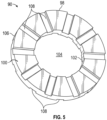
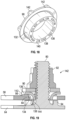
- the washer 90 has a first washer side 98 and a second washer side 100 opposite the first washer side 98 and is annular in shape, having an inner perimeter 102 defining a washer opening 104 and an outer perimeter 106.
- the washer 90 includes washer grooves 108 formed in the first washer side 98 and/or the second washer side 100, extending radially inwardly from the outer perimeter 106 to the inner perimeter 102.
- the inner perimeter 102 and the outer perimeter 106 are circular.
- the washer grooves 108 define cooling passages 96 between the washer 90 and the combustor shell 58 as shown in FIG. 4 , and cooling passages 96 between the washer 90 and the nut 92 as shown in FIG. 6 .
- the cooling flow 70 flows through the cooling passages 96 and between the stud shaft 88 and the shell stud opening 84 to impinge on the stud 80 and the standoffs 94.
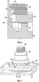
- the washer 90 may be formed as a "wavy washer" with the first washer side 98 and the second washer side 100 each having a wave shape, while maintaining a substantially constant washer thickness 110.
- cooling passages 96 are defined between the first washer side 98 and the combustor shell 58 and between the second washer side 100 and the nut 92 in an alternating pattern around the outer perimeter 106.
- the cooling flow 70 flows through the cooling passages 96 and between the stud shaft 88 and the shell stud opening 84 (both shown in FIG. 4 ) to impinge on the stud 80 and the standoffs 94.
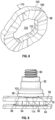
- the washer 90 includes a plurality of dimples formed therein, exhibited as a plurality of protrusions 114 in the first washer side 98 and corresponding recesses 112 at the second washer side 100.
- the protrusions 114 define the cooling passages 96 between the first washer side 98 and the combustor shell 58 around the outer perimeter 106.
- the cooling flow 70 flows through the cooling passages 96 and between the stud shaft 88 and the shell stud opening 84 (both shown in FIG. 4 ) to impinge on the stud 80 and the standoffs 94.
- the washer includes a plurality of through passages 116 extending from the outer perimeter 106 to the inner perimeter 102.
- Each through passage has a passage inlet 118 located at the outer perimeter 106, and a passage outlet 120 located at the inner perimeter 102.
- a cross-sectional size of the through passage 116 decreases with distance from the passage inlet 118.
- the through passage 116 extends along a passage central axis 122 non-perpendicular to the stud shaft 88.
- the passage inlet 118 and/or the passage outlet 120 are circular in cross-section, but it is to be appreciated that other cross-sectional shapes such as oval or elliptical may be utilized.
- the cooling flow 70 flows through the through passages 116 and between the stud shaft 88 and the shell stud opening 84 to impinge on the stud 80 and the standoffs 94.
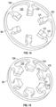
- the washer 90 includes a continuous outer perimeter 106 and a plurality of washer arms 124 extending radially inwardly from the outer perimeter 106.
- Airflow passages 126 are defined between adjacent washer arms 124 and the washer arms 124 further define the inner perimeter 102 of the washer 90. In some embodiments, adjacent washer arms 124 do not contact each other.
- the airflow passages 126 extend through the washer 90 from the first washer side 98 to the second washer side 100 and allow the cooling flow 70 to flow through the airflow passages 126 and then between the stud shaft 88 and the shell stud opening 84 to impinge on the stud 80 and the standoffs 94.
- the washer arms 124 include a web portion 128 and a relatively circumferentially wide end portion 130 located radially inboard of the web portion 128.
- the end portion 130 is substantially rectangular in an axial cross-section. It is to be appreciated, however, that the end portion 130 may be shapes other than rectangular such as a curvilinear shape as shown in FIG. 15 , depending on cooling flow 70 requirements and other factors. Further, in other embodiments, the washer arms 124 may be a constant width along their radial extent. In the embodiments of FIGs. 14 and 15 , six washer arms 124 are illustrated, while it is to be appreciated that other quantities of washer arms 124, such as 4, 5 or 8 washer arms 124, may be utilized in other embodiments.
- the washer 90 includes a sleeve 132, in some embodiments formed integrally with the washer 90.
- the sleeve 132 extends in an axial direction and in some embodiments through the shell stud opening 84 and in some embodiments extends at least partially into the intermediate passage 74 as shown.
- the sleeve 132 includes one or more sleeve passages 134 extending from a passage inlet 136 at the outer perimeter 106 of the washer 90, to a passage outlet 138 at a sleeve end 140 of the sleeve 132.
- the sleeve passages 134 allow the cooling flow 70 to flow through the shell stud opening 84 and out of the passage outlets 138 to impinge on the stud 80 and the standoffs 94.
- the passage inlets 136 are defined between adjacent washer ribs 142 that define the outer perimeter 106 of the washer 90.
- the washer 90 includes 6 washer ribs 142 and thus 5 passage inlets 136, while in other embodiments other quantities of washer ribs 142 and thus other quantities of passage inlets 136 may be utilized.
- the passage outlets 138 in the sleeve end 140 of the sleeve 132 may have an oval, elliptical, rectangular or other polygonal and/or curvilinear shape. In the embodiment illustrated, 12 passage outlets 138 are shown, but one skilled in the art will readily appreciate that other quantities of passage outlets 138, such as 1, 6, 8, or 10 or more passage outlets 138 may be utilized.
- the washer ribs 142 are located at the first washer side 98 and define the passage inlets 136 between the first washer side 98 and the combustor shell 58, and the sleeve passages 134 are similarly defined between a sleeve outer surface 144 and the combustor shell 58 and extend to passage outlets 138.
- the sleeve passages 134 allow the cooling flow 70 to flow through the shell stud opening 84 and out of the passage outlets 138 to impinge on the stud 80 and the standoffs 94.
Landscapes
- Engineering & Computer Science (AREA)
- Chemical & Material Sciences (AREA)
- Combustion & Propulsion (AREA)
- Mechanical Engineering (AREA)
- General Engineering & Computer Science (AREA)
- Turbine Rotor Nozzle Sealing (AREA)
Claims (9)
- Brennkammer (26) für ein Gasturbinentriebwerk (20), Folgendes umfassend:ein Brennkammergehäuse (58), das eine Gehäuseöffnung (84) durch dieses aufweist;eine Brennkammerplatte (64) mit einem daran befestigten Bolzen (80), wobei sich der Bolzen durch die Gehäuseöffnung erstreckt und der Bolzen einen Abstandshalter (94) beinhaltet, um einen Zwischendurchgang (74) zwischen dem Brennkammergehäuse und der Brennkammerplatte zu definieren;eine an dem Bolzen befestigte Halterung (92); undeine Zwischenscheibe (90), die den Bolzen umgibt und zwischen der Halterung und dem Brennkammergehäuse positioniert ist, wobei die Zwischenscheibe mindestens teilweise einen Kühlströmungsdurchgang (96) definiert, der dazu konfiguriert ist, einen Kühlluftstrom (70) durch die Gehäuseöffnung zu leiten, um den Kühlstrom auf mindestens einen von dem Bolzen oder dem Abstandshalter auftreffen zu lassen,wobei sich der Kühlströmungsdurchgang von einem Durchgangseinlass (118), der sich an einem äußeren Umfang (106) der Zwischenscheibe befindet, zu einem Durchgangsauslass (120) erstreckt, der sich an einem inneren Umfang (102) der Zwischenscheibe befindet, und wobei sich der Kühlströmungsdurchgang von dem Durchgangseinlass zu dem Durchgangsauslass verjüngt.
- Brennkammer nach Anspruch 1, wobei die Zwischenscheibe eine Nut (108) beinhaltet, um den Kühlströmungsdurchgang zwischen der Zwischenscheibe und dem Brennkammergehäuse und/oder zwischen der Zwischenscheibe und der Halterung zu definieren.
- Brennkammer nach Anspruch 1, wobei die Zwischenscheibe um einen äußeren Umfang (106) der Zwischenscheibe wellenförmig ist.
- Brennkammer nach Anspruch 1, wobei die Zwischenscheibe eine Zwischenscheibenhülse (132) beinhaltet, die sich durch die Gehäuseöffnung erstreckt, wobei der Kühlströmungsdurchgang mindestens teilweise durch die Zwischenscheibenhülse definiert ist, optional wobei der Kühlströmungsdurchgang einen Durchgangseinlass (136), der an einem äußeren Umfang (106) der Zwischenscheibe angeordnet ist, und einen Durchgangsauslass (138), der an einem axialen Ende (140) der Zwischenscheibenhülse angeordnet ist, beinhaltet.
- Brennkammer nach Anspruch 4, wobei die Zwischenscheibe eine Vielzahl von Rippen (142) beinhaltet, um den Durchgangseinlass zwischen der Zwischenscheibe und dem Brennkammergehäuse zu definieren.
- Zwischenscheibe (90) für eine Brennkammer (26) eines Gasturbinentriebwerks (20), Folgendes umfassend:eine erste Zwischenscheibenoberfläche (98);eine zweite Zwischenscheibenoberfläche (100) gegenüber der ersten Zwischenscheibenoberfläche;eine äußere Umfangsoberfläche (106), die sich zwischen der ersten Zwischenscheibenoberfläche und der zweiten Zwischenscheibenoberfläche erstreckt; undeinen Kühlströmungsdurchgang (96), um einen Kühlluftstrom (70) durch diesen durchzuleiten,wobei sich der Kühlströmungsdurchgang von einem Durchgangseinlass (118), der sich an einer äußeren Umfangsoberfläche (106) der Zwischenscheibe befindet, zu einem Durchgangsauslass (120), der sich an einer inneren Umfangsoberfläche (102) der Zwischenscheibe befindet, erstreckt und wobei sich der Kühlströmungsdurchgang von dem Durchgangseinlass zu dem Durchgangsauslass verjüngt.
- Zwischenscheibe nach Anspruch 6, beinhaltend eine Nut (108) an mindestens einer von der ersten Zwischenscheibenoberfläche oder der zweiten Zwischenscheibenoberfläche, um den Kühlströmungsdurchgang mindestens teilweise zu definieren.
- Zwischenscheibe nach Anspruch 6, ferner eine Zwischenscheibenhülse (132) umfassend, die sich von der ersten Oberfläche erstreckt, wobei der Kühlströmungsdurchgang mindestens teilweise durch die Zwischenscheibenhülse definiert ist.
- Gasturbinentriebwerk (20), Folgendes umfassend:einen Turbinenabschnitt (28); undeine beliebige Brennkammer nach den Ansprüchen 1 bis 5, die so konfiguriert ist, dass sie Kraftstoff verbrennt und Verbrennungsprodukte zu dem Turbinenabschnitt leitet.
Applications Claiming Priority (2)
| Application Number | Priority Date | Filing Date | Title |
|---|---|---|---|
| US15/476,431 US10690346B2 (en) | 2017-03-31 | 2017-03-31 | Washer for combustor assembly |
| EP18165053.2A EP3382279B1 (de) | 2017-03-31 | 2018-03-29 | Zwischenscheibe für brennkammeranordnung |
Related Parent Applications (2)
| Application Number | Title | Priority Date | Filing Date |
|---|---|---|---|
| EP18165053.2A Division EP3382279B1 (de) | 2017-03-31 | 2018-03-29 | Zwischenscheibe für brennkammeranordnung |
| EP18165053.2A Division-Into EP3382279B1 (de) | 2017-03-31 | 2018-03-29 | Zwischenscheibe für brennkammeranordnung |
Publications (2)
| Publication Number | Publication Date |
|---|---|
| EP4102137A1 EP4102137A1 (de) | 2022-12-14 |
| EP4102137B1 true EP4102137B1 (de) | 2025-05-07 |
Family
ID=61868253
Family Applications (2)
| Application Number | Title | Priority Date | Filing Date |
|---|---|---|---|
| EP22188403.4A Active EP4102137B1 (de) | 2017-03-31 | 2018-03-29 | Zwischenscheibe für brennkammeranordnung |
| EP18165053.2A Active EP3382279B1 (de) | 2017-03-31 | 2018-03-29 | Zwischenscheibe für brennkammeranordnung |
Family Applications After (1)
| Application Number | Title | Priority Date | Filing Date |
|---|---|---|---|
| EP18165053.2A Active EP3382279B1 (de) | 2017-03-31 | 2018-03-29 | Zwischenscheibe für brennkammeranordnung |
Country Status (2)
| Country | Link |
|---|---|
| US (1) | US10690346B2 (de) |
| EP (2) | EP4102137B1 (de) |
Families Citing this family (5)
| Publication number | Priority date | Publication date | Assignee | Title |
|---|---|---|---|---|
| KR102072101B1 (ko) * | 2017-10-30 | 2020-01-31 | 두산중공업 주식회사 | 연료 노즐 조립체 및 이를 포함하는 가스 터빈 |
| US11359810B2 (en) * | 2017-12-22 | 2022-06-14 | Raytheon Technologies Corporation | Apparatus and method for mitigating particulate accumulation on a component of a gas turbine |
| US11852184B2 (en) * | 2020-08-21 | 2023-12-26 | Rtx Corporation | Fastener element bonded to another fastener element |
| CN113530707A (zh) * | 2021-08-16 | 2021-10-22 | 中国航发贵阳发动机设计研究所 | 喷管隔热层结构及安装方法 |
| CN121739408A (zh) | 2022-04-06 | 2026-03-27 | 通用电气公司 | 燃烧器偏转器组件 |
Family Cites Families (12)
| Publication number | Priority date | Publication date | Assignee | Title |
|---|---|---|---|---|
| DD235699A1 (de) * | 1985-03-22 | 1986-05-14 | Oppach Schaltelektronik | Klemmscheibe zur beweglichen lagerung, sicherung oder befestigung von bauteilen auf wellen und dgl., vorzugsweise mit axialspiel |
| AUPM722194A0 (en) | 1994-08-02 | 1994-08-25 | Ani Corporation Limited, The | Bearer plate |
| US5707192A (en) * | 1996-11-06 | 1998-01-13 | Ford Motor Company | Panel--fastener connector clip |
| US20100263386A1 (en) | 2009-04-16 | 2010-10-21 | General Electric Company | Turbine engine having a liner |
| US8800298B2 (en) | 2009-07-17 | 2014-08-12 | United Technologies Corporation | Washer with cooling passage for a turbine engine combustor |
| GB0913580D0 (en) | 2009-08-05 | 2009-09-16 | Rolls Royce Plc | Combustor tile |
| FR2995041B1 (fr) * | 2012-08-28 | 2015-03-20 | Raymond A & Cie | Bague de fixation d'une tige sur un support et assemblage obtenu |
| GB201222311D0 (en) * | 2012-12-12 | 2013-01-23 | Rolls Royce Plc | A combusiton chamber |
| WO2015039075A1 (en) | 2013-09-16 | 2015-03-19 | United Technologies Corporation | Angled combustor liner cooling holes through transverse structure within a gas turbine engine combustor |
| DE102013226488A1 (de) | 2013-12-18 | 2015-06-18 | Rolls-Royce Deutschland Ltd & Co Kg | Unterlegscheibe einer Brennkammerschindel einer Gasturbine |
| US9822667B2 (en) | 2015-04-06 | 2017-11-21 | United Technologies Corporation | Tri-tab lock washer |
| GB201600760D0 (en) | 2016-01-15 | 2016-03-02 | Rolls Royce Plc | A combustion chamber arrangement |
-
2017
- 2017-03-31 US US15/476,431 patent/US10690346B2/en active Active
-
2018
- 2018-03-29 EP EP22188403.4A patent/EP4102137B1/de active Active
- 2018-03-29 EP EP18165053.2A patent/EP3382279B1/de active Active
Also Published As
| Publication number | Publication date |
|---|---|
| EP3382279B1 (de) | 2022-09-14 |
| EP4102137A1 (de) | 2022-12-14 |
| EP3382279A1 (de) | 2018-10-03 |
| US20180283687A1 (en) | 2018-10-04 |
| US10690346B2 (en) | 2020-06-23 |
Similar Documents
| Publication | Publication Date | Title |
|---|---|---|
| US10551065B2 (en) | Heat shield for a combustor | |
| EP2930428B1 (de) | Brennkammerwand für einen turbinenmotor | |
| EP3026343B1 (de) | Selbstkühlende düsenstruktur | |
| EP3447384B1 (de) | Brennkammerplattenkühlanordnungen | |
| EP3382279B1 (de) | Zwischenscheibe für brennkammeranordnung | |
| EP2932070B1 (de) | Gasturbinenbrennkammer-hitzeschild mit erhöhter filmkühlwirksamkeit | |
| EP3502562B1 (de) | Vorrichtung und verfahren zur verringerung der partikelansammlung auf einer komponente eines gasturbinentriebwerks | |
| EP4060236B1 (de) | Abgestufte cmc-brennkammerauskleidung | |
| EP2963346A1 (de) | Selbstkühlende öffnungsstruktur | |
| EP3042060B1 (de) | Gasturbinenmotor mit einer hitzeschild enthaltenden verbrennungsskammer | |
| EP2927597B1 (de) | Thermisch konforme durchführung | |
| EP2971973B1 (de) | Brennkammerplatte und brennkammer mit hitzeschild mit erhöhter beständigkeit | |
| US20180266686A1 (en) | Regulated combustor liner panel for a gas turbine engine combustor | |
| EP3511624B1 (de) | Brennkammer für eine gasturbine welche partikelansammlung verringert | |
| EP4071409B1 (de) | Gasturbinenmotor mit cmc-brennkammerplatte | |
| EP3748131B1 (de) | Anordnung zur strömungslenkung von einer äussere laufschaufelluftdichtung (boas) | |
| EP3640542B1 (de) | Brennkammerwand für einen gasturbinenmotor mit einer kühllochanordnung | |
| EP3611352B1 (de) | Befestigungsblock für die äussere luftdichtung einer schaufel mit konvektionskühlung | |
| EP3438538A2 (de) | Gasturbinenmotorkühlanordnung |
Legal Events
| Date | Code | Title | Description |
|---|---|---|---|
| PUAI | Public reference made under article 153(3) epc to a published international application that has entered the european phase |
Free format text: ORIGINAL CODE: 0009012 |
|
| STAA | Information on the status of an ep patent application or granted ep patent |
Free format text: STATUS: THE APPLICATION HAS BEEN PUBLISHED |
|
| AC | Divisional application: reference to earlier application |
Ref document number: 3382279 Country of ref document: EP Kind code of ref document: P |
|
| AK | Designated contracting states |
Kind code of ref document: A1 Designated state(s): AL AT BE BG CH CY CZ DE DK EE ES FI FR GB GR HR HU IE IS IT LI LT LU LV MC MK MT NL NO PL PT RO RS SE SI SK SM TR |
|
| STAA | Information on the status of an ep patent application or granted ep patent |
Free format text: STATUS: REQUEST FOR EXAMINATION WAS MADE |
|
| 17P | Request for examination filed |
Effective date: 20230613 |
|
| RBV | Designated contracting states (corrected) |
Designated state(s): AL AT BE BG CH CY CZ DE DK EE ES FI FR GB GR HR HU IE IS IT LI LT LU LV MC MK MT NL NO PL PT RO RS SE SI SK SM TR |
|
| RAP3 | Party data changed (applicant data changed or rights of an application transferred) |
Owner name: RTX CORPORATION |
|
| GRAP | Despatch of communication of intention to grant a patent |
Free format text: ORIGINAL CODE: EPIDOSNIGR1 |
|
| STAA | Information on the status of an ep patent application or granted ep patent |
Free format text: STATUS: GRANT OF PATENT IS INTENDED |
|
| INTG | Intention to grant announced |
Effective date: 20241202 |
|
| GRAS | Grant fee paid |
Free format text: ORIGINAL CODE: EPIDOSNIGR3 |
|
| GRAA | (expected) grant |
Free format text: ORIGINAL CODE: 0009210 |
|
| STAA | Information on the status of an ep patent application or granted ep patent |
Free format text: STATUS: THE PATENT HAS BEEN GRANTED |
|
| AC | Divisional application: reference to earlier application |
Ref document number: 3382279 Country of ref document: EP Kind code of ref document: P |
|
| AK | Designated contracting states |
Kind code of ref document: B1 Designated state(s): AL AT BE BG CH CY CZ DE DK EE ES FI FR GB GR HR HU IE IS IT LI LT LU LV MC MK MT NL NO PL PT RO RS SE SI SK SM TR |
|
| REG | Reference to a national code |
Ref country code: GB Ref legal event code: FG4D |
|
| REG | Reference to a national code |
Ref country code: CH Ref legal event code: EP |
|
| REG | Reference to a national code |
Ref country code: DE Ref legal event code: R096 Ref document number: 602018081859 Country of ref document: DE |
|
| REG | Reference to a national code |
Ref country code: IE Ref legal event code: FG4D |
|
| REG | Reference to a national code |
Ref country code: NL Ref legal event code: MP Effective date: 20250507 |
|
| PG25 | Lapsed in a contracting state [announced via postgrant information from national office to epo] |
Ref country code: FI Free format text: LAPSE BECAUSE OF FAILURE TO SUBMIT A TRANSLATION OF THE DESCRIPTION OR TO PAY THE FEE WITHIN THE PRESCRIBED TIME-LIMIT Effective date: 20250507 Ref country code: ES Free format text: LAPSE BECAUSE OF FAILURE TO SUBMIT A TRANSLATION OF THE DESCRIPTION OR TO PAY THE FEE WITHIN THE PRESCRIBED TIME-LIMIT Effective date: 20250507 Ref country code: PT Free format text: LAPSE BECAUSE OF FAILURE TO SUBMIT A TRANSLATION OF THE DESCRIPTION OR TO PAY THE FEE WITHIN THE PRESCRIBED TIME-LIMIT Effective date: 20250908 |
|
| REG | Reference to a national code |
Ref country code: LT Ref legal event code: MG9D |
|
| PG25 | Lapsed in a contracting state [announced via postgrant information from national office to epo] |
Ref country code: NO Free format text: LAPSE BECAUSE OF FAILURE TO SUBMIT A TRANSLATION OF THE DESCRIPTION OR TO PAY THE FEE WITHIN THE PRESCRIBED TIME-LIMIT Effective date: 20250807 Ref country code: GR Free format text: LAPSE BECAUSE OF FAILURE TO SUBMIT A TRANSLATION OF THE DESCRIPTION OR TO PAY THE FEE WITHIN THE PRESCRIBED TIME-LIMIT Effective date: 20250808 |
|
| PG25 | Lapsed in a contracting state [announced via postgrant information from national office to epo] |
Ref country code: NL Free format text: LAPSE BECAUSE OF FAILURE TO SUBMIT A TRANSLATION OF THE DESCRIPTION OR TO PAY THE FEE WITHIN THE PRESCRIBED TIME-LIMIT Effective date: 20250507 Ref country code: PL Free format text: LAPSE BECAUSE OF FAILURE TO SUBMIT A TRANSLATION OF THE DESCRIPTION OR TO PAY THE FEE WITHIN THE PRESCRIBED TIME-LIMIT Effective date: 20250507 |
|
| REG | Reference to a national code |
Ref country code: AT Ref legal event code: MK05 Ref document number: 1792826 Country of ref document: AT Kind code of ref document: T Effective date: 20250507 |
|
| PG25 | Lapsed in a contracting state [announced via postgrant information from national office to epo] |
Ref country code: BG Free format text: LAPSE BECAUSE OF FAILURE TO SUBMIT A TRANSLATION OF THE DESCRIPTION OR TO PAY THE FEE WITHIN THE PRESCRIBED TIME-LIMIT Effective date: 20250507 |
|
| PG25 | Lapsed in a contracting state [announced via postgrant information from national office to epo] |
Ref country code: HR Free format text: LAPSE BECAUSE OF FAILURE TO SUBMIT A TRANSLATION OF THE DESCRIPTION OR TO PAY THE FEE WITHIN THE PRESCRIBED TIME-LIMIT Effective date: 20250507 |
|
| PG25 | Lapsed in a contracting state [announced via postgrant information from national office to epo] |
Ref country code: AT Free format text: LAPSE BECAUSE OF FAILURE TO SUBMIT A TRANSLATION OF THE DESCRIPTION OR TO PAY THE FEE WITHIN THE PRESCRIBED TIME-LIMIT Effective date: 20250507 |
|
| PG25 | Lapsed in a contracting state [announced via postgrant information from national office to epo] |
Ref country code: RS Free format text: LAPSE BECAUSE OF FAILURE TO SUBMIT A TRANSLATION OF THE DESCRIPTION OR TO PAY THE FEE WITHIN THE PRESCRIBED TIME-LIMIT Effective date: 20250807 |
|
| PG25 | Lapsed in a contracting state [announced via postgrant information from national office to epo] |
Ref country code: IS Free format text: LAPSE BECAUSE OF FAILURE TO SUBMIT A TRANSLATION OF THE DESCRIPTION OR TO PAY THE FEE WITHIN THE PRESCRIBED TIME-LIMIT Effective date: 20250907 |
|
| PG25 | Lapsed in a contracting state [announced via postgrant information from national office to epo] |
Ref country code: LV Free format text: LAPSE BECAUSE OF FAILURE TO SUBMIT A TRANSLATION OF THE DESCRIPTION OR TO PAY THE FEE WITHIN THE PRESCRIBED TIME-LIMIT Effective date: 20250507 |
|
| PG25 | Lapsed in a contracting state [announced via postgrant information from national office to epo] |
Ref country code: SM Free format text: LAPSE BECAUSE OF FAILURE TO SUBMIT A TRANSLATION OF THE DESCRIPTION OR TO PAY THE FEE WITHIN THE PRESCRIBED TIME-LIMIT Effective date: 20250507 Ref country code: DK Free format text: LAPSE BECAUSE OF FAILURE TO SUBMIT A TRANSLATION OF THE DESCRIPTION OR TO PAY THE FEE WITHIN THE PRESCRIBED TIME-LIMIT Effective date: 20250507 |
|
| PG25 | Lapsed in a contracting state [announced via postgrant information from national office to epo] |
Ref country code: CZ Free format text: LAPSE BECAUSE OF FAILURE TO SUBMIT A TRANSLATION OF THE DESCRIPTION OR TO PAY THE FEE WITHIN THE PRESCRIBED TIME-LIMIT Effective date: 20250507 |
|
| PG25 | Lapsed in a contracting state [announced via postgrant information from national office to epo] |
Ref country code: EE Free format text: LAPSE BECAUSE OF FAILURE TO SUBMIT A TRANSLATION OF THE DESCRIPTION OR TO PAY THE FEE WITHIN THE PRESCRIBED TIME-LIMIT Effective date: 20250507 |
|
| PG25 | Lapsed in a contracting state [announced via postgrant information from national office to epo] |
Ref country code: SK Free format text: LAPSE BECAUSE OF FAILURE TO SUBMIT A TRANSLATION OF THE DESCRIPTION OR TO PAY THE FEE WITHIN THE PRESCRIBED TIME-LIMIT Effective date: 20250507 |
|
| PG25 | Lapsed in a contracting state [announced via postgrant information from national office to epo] |
Ref country code: IT Free format text: LAPSE BECAUSE OF FAILURE TO SUBMIT A TRANSLATION OF THE DESCRIPTION OR TO PAY THE FEE WITHIN THE PRESCRIBED TIME-LIMIT Effective date: 20250507 |
|
| REG | Reference to a national code |
Ref country code: DE Ref legal event code: R097 Ref document number: 602018081859 Country of ref document: DE |
|
| PLBE | No opposition filed within time limit |
Free format text: ORIGINAL CODE: 0009261 |
|
| STAA | Information on the status of an ep patent application or granted ep patent |
Free format text: STATUS: NO OPPOSITION FILED WITHIN TIME LIMIT |
|
| REG | Reference to a national code |
Ref country code: CH Ref legal event code: L10 Free format text: ST27 STATUS EVENT CODE: U-0-0-L10-L00 (AS PROVIDED BY THE NATIONAL OFFICE) Effective date: 20260318 |
|
| PGFP | Annual fee paid to national office [announced via postgrant information from national office to epo] |
Ref country code: GB Payment date: 20260219 Year of fee payment: 9 |
|
| PGFP | Annual fee paid to national office [announced via postgrant information from national office to epo] |
Ref country code: DE Payment date: 20260219 Year of fee payment: 9 |
|
| 26N | No opposition filed |
Effective date: 20260210 |
|
| PGFP | Annual fee paid to national office [announced via postgrant information from national office to epo] |
Ref country code: FR Payment date: 20260219 Year of fee payment: 9 |