EP4102087A1 - Sliding member, production method of sliding member, and evaluation method of sliding member - Google Patents
Sliding member, production method of sliding member, and evaluation method of sliding member Download PDFInfo
- Publication number
- EP4102087A1 EP4102087A1 EP22173518.6A EP22173518A EP4102087A1 EP 4102087 A1 EP4102087 A1 EP 4102087A1 EP 22173518 A EP22173518 A EP 22173518A EP 4102087 A1 EP4102087 A1 EP 4102087A1
- Authority
- EP
- European Patent Office
- Prior art keywords
- sliding face
- roughness
- sliding
- denoted
- face
- Prior art date
- Legal status (The legal status is an assumption and is not a legal conclusion. Google has not performed a legal analysis and makes no representation as to the accuracy of the status listed.)
- Granted
Links
Images


Classifications
-
- F—MECHANICAL ENGINEERING; LIGHTING; HEATING; WEAPONS; BLASTING
- F16—ENGINEERING ELEMENTS AND UNITS; GENERAL MEASURES FOR PRODUCING AND MAINTAINING EFFECTIVE FUNCTIONING OF MACHINES OR INSTALLATIONS; THERMAL INSULATION IN GENERAL
- F16C—SHAFTS; FLEXIBLE SHAFTS; ELEMENTS OR CRANKSHAFT MECHANISMS; ROTARY BODIES OTHER THAN GEARING ELEMENTS; BEARINGS
- F16C17/00—Sliding-contact bearings for exclusively rotary movement
- F16C17/12—Sliding-contact bearings for exclusively rotary movement characterised by features not related to the direction of the load
-
- F—MECHANICAL ENGINEERING; LIGHTING; HEATING; WEAPONS; BLASTING
- F16—ENGINEERING ELEMENTS AND UNITS; GENERAL MEASURES FOR PRODUCING AND MAINTAINING EFFECTIVE FUNCTIONING OF MACHINES OR INSTALLATIONS; THERMAL INSULATION IN GENERAL
- F16C—SHAFTS; FLEXIBLE SHAFTS; ELEMENTS OR CRANKSHAFT MECHANISMS; ROTARY BODIES OTHER THAN GEARING ELEMENTS; BEARINGS
- F16C17/00—Sliding-contact bearings for exclusively rotary movement
- F16C17/02—Sliding-contact bearings for exclusively rotary movement for radial load only
-
- F—MECHANICAL ENGINEERING; LIGHTING; HEATING; WEAPONS; BLASTING
- F16—ENGINEERING ELEMENTS AND UNITS; GENERAL MEASURES FOR PRODUCING AND MAINTAINING EFFECTIVE FUNCTIONING OF MACHINES OR INSTALLATIONS; THERMAL INSULATION IN GENERAL
- F16C—SHAFTS; FLEXIBLE SHAFTS; ELEMENTS OR CRANKSHAFT MECHANISMS; ROTARY BODIES OTHER THAN GEARING ELEMENTS; BEARINGS
- F16C33/00—Parts of bearings; Special methods for making bearings or parts thereof
- F16C33/02—Parts of sliding-contact bearings
-
- F—MECHANICAL ENGINEERING; LIGHTING; HEATING; WEAPONS; BLASTING
- F16—ENGINEERING ELEMENTS AND UNITS; GENERAL MEASURES FOR PRODUCING AND MAINTAINING EFFECTIVE FUNCTIONING OF MACHINES OR INSTALLATIONS; THERMAL INSULATION IN GENERAL
- F16C—SHAFTS; FLEXIBLE SHAFTS; ELEMENTS OR CRANKSHAFT MECHANISMS; ROTARY BODIES OTHER THAN GEARING ELEMENTS; BEARINGS
- F16C33/00—Parts of bearings; Special methods for making bearings or parts thereof
- F16C33/02—Parts of sliding-contact bearings
- F16C33/04—Brasses; Bushes; Linings
- F16C33/06—Sliding surface mainly made of metal
-
- F—MECHANICAL ENGINEERING; LIGHTING; HEATING; WEAPONS; BLASTING
- F16—ENGINEERING ELEMENTS AND UNITS; GENERAL MEASURES FOR PRODUCING AND MAINTAINING EFFECTIVE FUNCTIONING OF MACHINES OR INSTALLATIONS; THERMAL INSULATION IN GENERAL
- F16C—SHAFTS; FLEXIBLE SHAFTS; ELEMENTS OR CRANKSHAFT MECHANISMS; ROTARY BODIES OTHER THAN GEARING ELEMENTS; BEARINGS
- F16C33/00—Parts of bearings; Special methods for making bearings or parts thereof
- F16C33/02—Parts of sliding-contact bearings
- F16C33/04—Brasses; Bushes; Linings
- F16C33/06—Sliding surface mainly made of metal
- F16C33/12—Structural composition; Use of special materials or surface treatments, e.g. for rust-proofing
-
- G—PHYSICS
- G06—COMPUTING OR CALCULATING; COUNTING
- G06F—ELECTRIC DIGITAL DATA PROCESSING
- G06F17/00—Digital computing or data processing equipment or methods, specially adapted for specific functions
- G06F17/10—Complex mathematical operations
- G06F17/11—Complex mathematical operations for solving equations, e.g. nonlinear equations, general mathematical optimization problems
-
- F—MECHANICAL ENGINEERING; LIGHTING; HEATING; WEAPONS; BLASTING
- F16—ENGINEERING ELEMENTS AND UNITS; GENERAL MEASURES FOR PRODUCING AND MAINTAINING EFFECTIVE FUNCTIONING OF MACHINES OR INSTALLATIONS; THERMAL INSULATION IN GENERAL
- F16C—SHAFTS; FLEXIBLE SHAFTS; ELEMENTS OR CRANKSHAFT MECHANISMS; ROTARY BODIES OTHER THAN GEARING ELEMENTS; BEARINGS
- F16C2202/00—Solid materials defined by their properties
- F16C2202/02—Mechanical properties
- F16C2202/04—Hardness
-
- F—MECHANICAL ENGINEERING; LIGHTING; HEATING; WEAPONS; BLASTING
- F16—ENGINEERING ELEMENTS AND UNITS; GENERAL MEASURES FOR PRODUCING AND MAINTAINING EFFECTIVE FUNCTIONING OF MACHINES OR INSTALLATIONS; THERMAL INSULATION IN GENERAL
- F16C—SHAFTS; FLEXIBLE SHAFTS; ELEMENTS OR CRANKSHAFT MECHANISMS; ROTARY BODIES OTHER THAN GEARING ELEMENTS; BEARINGS
- F16C2240/00—Specified values or numerical ranges of parameters; Relations between them
- F16C2240/40—Linear dimensions, e.g. length, radius, thickness, gap
- F16C2240/54—Surface roughness
Definitions
- the present invention relates to a sliding member, a production method of a sliding member, and an evaluation method of a sliding member.
- a shaft member such as a crankshaft, an intermediate shaft, a propulsion shaft, or the like for ship is slidably supported by a bearing member such as a slide bearing or the like. Furthermore, a lubricating liquid is supplied to a gap between the shaft member and the bearing member. The lubricating liquid forms a lubricating film between the shaft member and the bearing member to inhibit a seizure therebetween. Meanwhile, even in a case in which the lubricating film is formed between the shaft member and the bearing member, if the surface roughness of the shaft member and the bearing member is high as compared with the thickness of the lubricating film, a possibility of a seizure between these members is increased.
- Patent Document 1 discloses a combined sliding member adapted to a reduction in friction of an internal combustion engine.
- Patent Document 1 Japanese Unexamined Patent Application, Publication No. 2004-116707
- a sliding face of the shaft member may be manually polished after mechanical processing for the purpose of achieving sufficient dimension accuracy.
- the sliding face which has been manually polished may have an increased radius of curvature of roughness projections, and thus it may be likely that a seizure occurs on the sliding face.
- the radius of curvature of roughness projections on the sliding face is not sufficiently considered, and thus it may be difficult to sufficiently inhibit a seizure of the sliding face.
- the present invention was made in view of the foregoing circumstances, and an object of the present invention is to provide a sliding member which enables inhibition of a seizure on a sliding face.
- R ac ⁇ + 4 ⁇ ⁇ 20 1.045 ⁇ 10 ⁇ 4 ⁇ ⁇ 4.3 ⁇ 1.5 ⁇ 2 E * 0.147
- ⁇ represents a value [ ⁇ m] calculated according to formula 2 in a case in which an average value of heights of roughness projection apices of the first sliding face is denoted by ⁇ A [ ⁇ m], and an average value of heights of roughness projection apices of the second sliding face is denoted by ⁇ B [ ⁇ m];
- ⁇ represents a value [ ⁇ m] calculated according to formula 3 in a case in which a root mean square of the heights of the roughness projection apices of the first sliding face is denoted by ⁇ A [ ⁇ m], and a root mean square of the heights of the roughness projection apices of the second sliding face is denoted by ⁇ B [ ⁇ m];
- ⁇ represents a value [ ⁇ m -2 ] calculated according to formula 4 in a case in which a roughness projection density per unit area of the first sliding face is denoted by ⁇ A [ ⁇ m -2 ], and a roughness projection density per unit area of the second sliding face is denoted by ⁇ B
- the sliding member according to the one aspect of the present invention enables inhibition of a seizure on the sliding face.
- a sliding member comprises: a shaft member having a first sliding face; and a bearing member having a second sliding face which slidably supports the first sliding face, wherein the first sliding face and the second sliding face differ in hardness, and a roughness parameter R ac calculated according to the following formula 1 is less than or equal to 0.276.
- R ac ⁇ + 4 ⁇ ⁇ 20 1.045 ⁇ 10 ⁇ 4 ⁇ ⁇ 4.3 ⁇ 1.5 ⁇ 2 E * 0.147
- ⁇ represents a value [ ⁇ m] calculated according to the following formula 2 in a case in which an average value of heights of roughness projection apices of the first sliding face is denoted by ⁇ A [ ⁇ m], and an average value of heights of roughness projection apices of the second sliding face is denoted by ⁇ B [ ⁇ m];
- ⁇ represents a value [ ⁇ m] calculated according to the following formula 3 in a case in which a root mean square of the heights of the roughness projection apices of the first sliding face is denoted by ⁇ A [ ⁇ m], and a root mean square of the heights of the roughness projection apices of the second sliding face is denoted by ⁇ B [ ⁇ m];
- ⁇ represents a value [ ⁇ m -2 ] calculated according to the following formula 4 in a case in which a roughness projection density per unit area of the first sliding face is denoted by ⁇ A [ ⁇ m -2 ], and a roughness projection density per unit area of the second sliding face is de
- a roughness contact stress P a [GPa] between two sliding faces is calculated according to the following formula 5 using a model of Greenwood-Tripp, in a case in which a distance between the sliding faces is denoted by h [ ⁇ m].
- h is represented by the following formula 6 based on the following formula 5.
- P lim a limit roughness contact stress at which a seizure occurs
- h is represented by the following formula 7 as a distance h lim between the sliding faces which is a limit of occurrence of a seizure.
- the distance h lim is determined by only roughness characteristics and material properties of the two sliding faces, and thus h lim can be defined as the roughness parameter R ac . Accordingly, the sliding member enables inhibition of a seizure on the sliding face by controlling the roughness parameter R ac in the formula 1 obtained by setting P lim to an appropriate value, to be less than or equal to the above value.
- the first sliding face and the second sliding face of the sliding member differ in hardness
- the first sliding face comes into contact with the second sliding face
- microscopic projections on a surface having a higher hardness of these sliding faces are likely to be maintained.
- a surface having a lower hardness of the first sliding face and the second sliding face is easily plastically deformed.
- the sliding face having a lower hardness can be polished by the contact between the first sliding face and the second sliding face, and it is easy to control the roughness parameter R ac to be less than or equal to the lower limit.
- the roughness parameter R ac is preferably calculated such that, of the first sliding face and the second sliding face, the sliding face having a lower hardness is defined as a mirror surface having no roughness projection.
- R ac in the formula 1 can be calculated more easily.
- a lubricating liquid is preferably supplied between the first sliding face and the second sliding face.
- a shaft diameter of the first sliding face of the shaft member may be greater than or equal to 180 mm.
- ⁇ is less than or equal to 0.232, and ⁇ is less than or equal to 0.209. Setting ⁇ and ⁇ to be less than or equal to the respective upper limit values enables easy inhibition of a seizure on the sliding face.
- An other aspect of the present invention is a production method of a sliding member comprising: a shaft member having a first sliding face; and a bearing member having a second sliding face which slidably supports the first sliding face, wherein the first sliding face and the second sliding face differ in hardness, the production method comprising: a smoothing step of smoothing, of the first sliding face and the second sliding face, a sliding face having a higher hardness such that a roughness parameter R ac calculated according to the following formula 1 is less than or equal to 0.276.
- R ac ⁇ + 4 ⁇ ⁇ 20 1.045 ⁇ 10 ⁇ 4 ⁇ ⁇ 4.3 ⁇ 1.5 ⁇ 2 E * 0.147
- ⁇ represents a value [ ⁇ m] calculated according to the following formula 2 in a case in which an average value of heights of roughness projection apices of the first sliding face is denoted by ⁇ A [ ⁇ m], and an average value of heights of roughness projection apices of the second sliding face is denoted by ⁇ B [ ⁇ m];
- ⁇ represents a value [ ⁇ m] calculated according to the following formula 3 in a case in which a root mean square of the heights of the roughness projection apices of the first sliding face is denoted by ⁇ A [ ⁇ m], and a root mean square of the heights of the roughness projection apices of the second sliding face is denoted by ⁇ B [ ⁇ m];
- ⁇ represents a value [ ⁇ m -2 ] calculated according to the following formula 4 in a case in which a roughness projection density per unit area of the first sliding face is denoted by ⁇ A [ ⁇ m -2 ], and a roughness projection density per unit area of the second sliding face is de
- a sliding member by smoothing in the smoothing step, of the first sliding face and the second sliding face, the sliding face having a higher hardness such that the roughness parameter R ac in the formula 1 is less than or equal to the above value, a sliding member which enables inhibition of a seizure on a sliding face can be produced.
- An other aspect of the present invention is an evaluation method of a sliding member comprising: a shaft member having a first sliding face; and a bearing member having a second sliding face which slidably supports the first sliding face, the evaluation method comprising: an evaluating step of evaluating a possibility of occurrence of a seizure between the first sliding face and the second sliding face based on a roughness parameter R ac calculated according to the following formula 1.
- R ac ⁇ + 4 ⁇ ⁇ 20 1.045 ⁇ 10 ⁇ 4 ⁇ ⁇ 4.3 ⁇ 1.5 ⁇ 2 E * 0.147
- ⁇ represents a value [ ⁇ m] calculated according to the following formula 2 in a case in which an average value of heights of roughness projection apices of the first sliding face is denoted by ⁇ A [ ⁇ m], and an average value of heights of roughness projection apices of the second sliding face is denoted by ⁇ B [ ⁇ m];
- ⁇ represents a value [ ⁇ m] calculated according to the following formula 3 in a case in which a root mean square of the heights of the roughness projection apices of the first sliding face is denoted by ⁇ A [ ⁇ m], and a root mean square of the heights of the roughness projection apices of the second sliding face is denoted by ⁇ B [ ⁇ m];
- ⁇ represents a value [( ⁇ m -2 ] calculated according to the following formula 4 in a case in which a roughness projection density per unit area of the first sliding face is denoted by ⁇ A [ ⁇ m -2 ], and a roughness projection density per unit area of the second sliding face is
- the "roughness projection apices" are determined by the following procedure based on a roughness curve with a measured length of 4.0 mm which is measured at a cut-off value of 0.25 mm according to JIS-B0601 (2013). Firstly, an average line of the roughness curve is set according to JIS-B0601 (2013), and with the average line as a reference, heights of measurement points above the average line are defined as positive values, while heights of measurement points below the average line are defined as negative values. An average value of the heights of all the measurement points having positive values is denoted by Thr0.
- a measurement point which is higher than measurement points adjacent thereto on both sides and has a height greater than -Thr0 is assumed to be a temporary apex.
- a measurement point having a smallest height is defined as a valley.
- height differences between a temporary apex and left and right valleys adjacent to the temporary apex are respectively determined; in a case in which either of these height differences is less than 0.2 ⁇ Thr0, the corresponding temporary apex is excluded.
- remaining temporary apices are determined as roughness projection apices.
- a measurement point having a largest gradient of the straight line is determined for each of the left and right sides of the roughness projection apex and defined as an end of the roughness projection apex.
- a "height of a roughness projection apex” refers to a height of a roughness projection apex with the above-mentioned average line as a reference.
- the "average value of the heights of the roughness projection apices” as referred to herein means an arithmetic mean value of the heights of all the roughness projection apices on the roughness curve.
- the "root mean square of the heights of the roughness projection apices” as referred to herein means a square root of the arithmetic mean of squares of the heights of the roughness projection apices relative to the average value of the heights of all the roughness projection apices on the roughness curve.
- the "radius of curvature of roughness projections" is calculated by the following procedure. Firstly, a roughness curve between both ends of each roughness projection apex is approximated by the method of least squares. Then, in a case in which a quadratic coefficient of a quadratic function obtained as a result of the approximation by the method of least squares is denoted by a, the radius of curvature of each roughness projection apex is calculated as -0.5/a.
- the "median of radius of curvature of roughness projections in an entirety of the first sliding face and the second sliding face" as referred to herein means a median of radius of curvature of all the roughness projection apices on the roughness curve of the first sliding face and the roughness curve of the second sliding face.
- the "roughness projection density per unit area” refers to a density calculated as (m/L) 2 in a case in which a measured length of the roughness curve, i.e. a length of the horizontal axis of the roughness curve is denoted by L, and a number of roughness projection apices on the roughness curve is denoted by m.
- the "equivalent longitudinal elastic modulus” refers to a value of E [GPa] calculated according to the following formula 8 in a case in which a Poisson's ratio of the first sliding face is denoted by v A , a longitudinal elastic modulus of the first sliding face is denoted by E A [GPa], a Poisson's ratio of the second sliding face is denoted by v B , and a longitudinal elastic modulus of the second sliding face is denoted by E B [GPa].
- E * 2 1 ⁇ ⁇ A 2 E A + 1 ⁇ ⁇ B 2 E B
- a sliding face having a lower hardness is defined as a mirror surface having no roughness projection
- the average value of the heights of the roughness projection apices, the root mean square of the heights of the roughness projection apices, and the roughness projection density per unit area of the sliding face having a lower hardness are converted to 0, and the median of radius of curvature of roughness projections in the entirety of the first sliding face and the second sliding face is converted to a median of radius of curvature of roughness projections on the sliding face having a higher hardness.
- a sliding member in FIG. 1 is, for example, a sliding member for ship which is disposed on a ship.
- the sliding member comprises: a shaft member 1 having a first sliding face 11; and a bearing member 2 having a second sliding face 21 which slidably supports the first sliding face 11.
- the first sliding face 11 and the second sliding face 21 face each other.
- the second sliding face 21 surrounds an outer peripheral face of the first sliding face 11.
- a lubricating liquid 3 is supplied between the first sliding face 11 and the second sliding face 21.
- the shaft member 1 is a rotating body which rotates in a circumferential direction with respect to the bearing member 2.
- the shaft member 1 is exemplified by a crankshaft, an intermediate shaft, a propulsion shaft, and the like for ship.
- Examples of a material of the shaft member 1 include carbon steel, low-alloy steel, and the like.
- a shaft diameter d of the first sliding face 11 is not particularly limited, and may be greater than or equal to 180 mm. Furthermore, the shaft diameter d of the first sliding face 11 may be greater than or equal to 280 mm, and may be greater than or equal to 360 mm. In the shaft member 1 having a large diameter in which the shaft diameter d of the first sliding face 11 is greater than or equal to the lower limit value, it may be desirable that the first sliding face 11 is manually polished. Even in such a case, the sliding member enables easy inhibition of a seizure between the first sliding face 11 and the second sliding face 21.
- the upper limit of the shaft diameter d of the first sliding face 11 is preferably 1,500 mm, more preferably 1,400 mm, and still more preferably 1,300 mm.
- the shaft diameter d of the first sliding face 11 is greater than the upper limit value, the sliding member becomes too large, and a demand for reduction in device size may be contradicted.
- the bearing member 2 is exemplified by a crank bearing, an intermediate bearing, a propulsion bearing, and the like for ship.
- Examples of a material of the bearing member 2 include white metal, trimetal, kelmet, aluminum alloy, and the like.
- the roughness parameter R ac which is calculated according to the following formula 1 and relates to the first sliding face 11 and the second sliding face 21 is less than or equal to 0.276.
- R ac ⁇ + 4 ⁇ ⁇ 20 1.045 ⁇ 10 ⁇ 4 ⁇ ⁇ 4.3 ⁇ 1.5 ⁇ 2 E ⁇ 0.147
- ⁇ represents a value [ ⁇ m] calculated according to the following formula 2 in a case in which an average value of heights of roughness projection apices of the first sliding face 11 is denoted by ⁇ A [ ⁇ m], and an average value of heights of roughness projection apices of the second sliding face 21 is denoted by ⁇ B [ ⁇ m];
- ⁇ represents a value [ ⁇ m] calculated according to the following formula 3 in a case in which a root mean square of the heights of the roughness projection apices of the first sliding face 11 is denoted by ⁇ A [ ⁇ m], and a root mean square of the heights of the roughness projection apices of the second sliding face 21 is denoted by ⁇ B [ ⁇ m];
- ⁇ represents a value [ ⁇ m 2 ] calculated according to the following formula 4 in a case in which a roughness projection density per unit area of the first sliding face 11 is denoted by ⁇ A [ ⁇ m -2 ], and a roughness projection density per unit area of the second
- the upper limit of the roughness parameter R ac is preferably 0.185, and more preferably 0.141. When the roughness parameter R ac is greater than the upper limit, it may be difficult to inhibit a seizure between the first sliding face 11 and the second sliding face 21.
- the lower limit of ⁇ is not particularly limited, and may be, for example, greater than 51, may be greater than 55, and may be greater than 58.
- the value of ⁇ is likely to be increased in the case in which the first sliding face 11 manually polished. Even in such a case, the sliding member enables easy inhibition of a seizure between the first sliding face 11 and the second sliding face 21.
- the upper limit of ⁇ is preferably 338, more preferably 330, and still more preferably 320.
- ⁇ is greater than the upper limit value, it may be difficult to inhibit a seizure between the first sliding face 11 and the second sliding face 21.
- ⁇ is less than or equal to 0.232, and ⁇ is less than or equal to 0.209.
- Setting ⁇ and ⁇ to be less than or equal to the respective upper limit values enables easy inhibition of a seizure between the first sliding face 11 and the second sliding face 21. More specifically, the value of ⁇ is increased when the first sliding face 11 is manually polished; as a result, the value of the roughness parameter R ac in the formula 1 is likely to be increased. Even in such a case, by controlling ⁇ and ⁇ to be less than or equal to the respective upper limit values, the value of the roughness parameter R ac can be easily decreased. Thus, a seizure between the first sliding face 11 and the second sliding face 21 is easily inhibited.
- the upper limit of ⁇ is more preferably 0.181, and still more preferably 0.166.
- the lower limit of ⁇ is preferably 0.034, more preferably 0.040, and still more preferably 0.050.
- ⁇ is greater than the upper limit value, it may be difficult to inhibit a seizure between the first sliding face 11 and the second sliding face 21.
- ⁇ is less than the lower limit value, polishing other than the manual polishing is further required, and thus the production cost of the sliding member may be increased.
- the upper limit of ⁇ is more preferably 0.166, and still more preferably 0.130.
- the lower limit of ⁇ is preferably 0.052, more preferably 0.060, and still more preferably 0.070.
- ⁇ is greater than the upper limit value, it may be difficult to inhibit a seizure between the first sliding face 11 and the second sliding face 21.
- ⁇ is less than the lower limit value, polishing other than the manual polishing is further required, and thus the production cost of the sliding member may be increased.
- the first sliding face 11 and the second sliding face 21 differ in hardness.
- the hardness of the first sliding face 11 may be higher than the hardness of the second sliding face 21.
- the first sliding face 11 and the second sliding face 21 differ in hardness, in a case in which the first sliding face 11 comes into contact with the second sliding face 21, microscopic projections on a surface having a higher hardness of these sliding faces are likely to be maintained.
- a surface having a lower hardness of the first sliding face 11 and the second sliding face 21 is easily plastically deformed due to rotational contact between the sliding faces.
- the sliding face having a lower hardness can be regarded as a surface having substantially the same level of roughness projections as the sliding face having a higher hardness, or as a mirror surface having substantially no roughness projection.
- the average value of the heights of the roughness projection apices, the root mean square of the heights of the roughness projection apices, and the roughness projection density per unit area of the sliding face having a lower hardness of the first sliding face 11 and the second sliding face 21 may be converted to values of the sliding face having a higher hardness, and these values may be converted to 0.
- ⁇ may be converted to the median of radius of curvature of roughness projections on the sliding face having a higher hardness.
- R ac in the formula 1 can be calculated more easily in consideration of future plastic deformation of the sliding face having a lower hardness.
- Ra c an effect of inhibiting a seizure between the first sliding face 11 and the second sliding face 21 is easily obtained in a case in which, of the first sliding face 11 and the second sliding face 21, the sliding face having a higher hardness is manually polished.
- the "hardness” as referred to herein means a Brinell hardness as defined in JIS-Z2243 (2016).
- a difference in hardness between the first sliding face 11 and the second sliding face 21 is preferably large.
- the lower limit of the difference in hardness between the first sliding face 11 and the second sliding face 21 is preferably 100 HB, more preferably 130 HB, and still more preferably 150 HB.
- the lubricating liquid 3 forms a lubricating film between the first sliding face 11 and the second sliding face 21 to increase slipperiness between the first sliding face 11 and the second sliding face 21.
- the lubricating liquid 3 is exemplified by a lubricating oil such as a paraffin base oil, seawater, and the like.
- the lubricating liquid 3 facilitates maintaining a space between the first sliding face 11 and the second sliding face 21 in a fluid lubrication state.
- the fluid lubrication state between the first sliding face 11 and the second sliding face 21 enables inhibition of a seizure between the first sliding face 11 and the second sliding face 21.
- the "fluid lubrication state" as referred to herein means a state of fluid lubrication which is sorted using a Stribeck curve.
- the sliding member enables inhibition of a seizure on the sliding face by controlling the roughness parameter R ac in the formula 1 to be less than or equal to the above value.
- the sliding member for example, in a case in which the shaft member 1 is a crankshaft for ship, a crankpin is eccentric to a journal, and thus the dimension accuracy of the sliding face due to mechanical processing is likely to be insufficient. More specifically, for example, in a case in which the first sliding face 11 is provided on a peripheral face of the crankpin, manual polishing of the first sliding face 11 is likely to be required.
- the first sliding face 11 which has been manually polished may have an increased radius of curvature of roughness projections, and thus it may be likely that a seizure occurs on the first sliding face 11. In other words, in the case in which the shaft member 1 is a crankshaft for ship, the value of ⁇ is likely to be increased.
- the sliding member Even in such a case, in the sliding member, other roughness parameters such as ⁇ , ⁇ , and the like are controlled such that the roughness parameter R ac in the formula 1 is less than or equal to the above value. Accordingly, even in the case in which the shaft member 1 is a crankshaft for ship, the sliding member enables appropriate inhibition of a seizure on the sliding face.
- the production method of the sliding member comprising: the shaft member 1 having the first sliding face 11; and the bearing member 2 having the second sliding face 21 which slidably supports the first sliding face 11, wherein the first sliding face 11 and the second sliding face 21 differ in hardness, comprises: a smoothing step S1 of smoothing, of the first sliding face 11 and the second sliding face 21, the sliding face having a higher hardness.
- the smoothing step S1 is performed after the shaft member 1 and the bearing member 2 are formed by mechanical processing.
- the dimension accuracy of the shaft member 1 and the bearing member 2 after the mechanical processing may be insufficient, and thus manual polishing of the sliding face having a higher hardness of the first sliding face 11 and the second sliding face 21 (for example, the first sliding face 11 of the shaft member 1) may be required in order to improve the dimension accuracy.
- the radius of curvature of roughness projections on the first sliding face 11 is likely to be increased.
- the value of ⁇ after the mechanical processing is within a range of greater than or equal to 23.78 and less than or equal to 51.00
- the value of ⁇ after the manual polishing of the first sliding face 11 may be increased to be within a range of greater than or equal to 55.79 and less than or equal to 337.9.
- the roughness parameter R ac calculated according to the formula 1 is increased, and therefore a seizure is likely to occur between the shaft member 1 and the bearing member 2.
- the sliding face having a higher hardness is smoothed such that the roughness parameter R ac calculated according to the formula 1 is less than or equal to 0.276.
- the values such as ⁇ , ⁇ , and the like of the sliding face having a higher hardness of the first sliding face 11 and the second sliding face 21 are decreased such that the roughness parameter R ac is less than or equal to 0.276 even in the case in which the value of ⁇ is large.
- the sliding face is preferably manually polished.
- the sliding face having a lower hardness can be regarded as a surface having substantially the same level of roughness projections as the sliding face having a higher hardness, or as a mirror surface having substantially no roughness projection.
- the average value of the heights of the roughness projection apices, the root mean square of the heights of the roughness projection apices, and the roughness projection density per unit area of the sliding face having a lower hardness of the first sliding face 11 and the second sliding face 21 may be converted to values of the sliding face having a higher hardness, and these values may be converted to 0.
- ⁇ may be converted to the median of radius of curvature of roughness projections on the sliding face having a higher hardness.
- the sliding face having a lower hardness as a surface having the same level of roughness projections as the sliding face having a higher hardness, or as a mirror surface having no roughness projection R ac in the formula 1 can be calculated more easily.
- At least one of the first sliding face 11 and the second sliding face 21 is preferably polished such that the value of ⁇ is less than or equal to 0.232 and the value of ⁇ is less than or equal to 0.209.
- a method of smoothing at least one of the first sliding face 11 of the shaft member 1 and the second sliding face 21 is not particularly limited, and is exemplified by polishing of at least one of the first sliding face 11 and the second sliding face 21 with sandpaper, and the like.
- sandpaper having a roughness of greater than or equal to 240 mesh is preferably used.
- sandpaper of an appropriate mesh the values of ⁇ and ⁇ are easily controlled to be small, while the value of ⁇ is likely to be increased. As a result, a seizure between the first sliding face 11 and the second sliding face 21 is easily inhibited.
- the roughness parameter R ac in the formula 1 is controlled by controlling in the smoothing step S1, the roughness parameter R ac in the formula 1 to be less than or equal to the above value, a sliding member which enables inhibition of a seizure on a sliding face can be produced.
- the evaluation method of the sliding member comprising: the shaft member having the first sliding face; and the bearing member having the second sliding face which slidably supports the first sliding face, comprises: an evaluating step S1 of evaluating a possibility of occurrence of a seizure between the first sliding face and the second sliding face based on a roughness parameter R ac calculated according to the following formula 1.
- the evaluation method is suitable for evaluating, whether a seizure occurs between the first sliding face 11 and the second sliding face 21 of the sliding member in FIG. 1 .
- a case in which the roughness parameter R ac is less than or equal to a threshold value is evaluated as a low possibility of occurrence of the seizure; conversely, a case in which the roughness parameter R ac is greater than the threshold value is evaluated as a high possibility of occurrence of the seizure.
- R ac ⁇ + 4 ⁇ ⁇ 20 1.045 ⁇ 10 ⁇ 4 ⁇ ⁇ 4.3 ⁇ 1.5 ⁇ 2 E ⁇ 0.147
- ⁇ represents a value [ ⁇ m] calculated according to the following formula 2 in a case in which an average value of heights of roughness projection apices of the first sliding face is denoted by ⁇ A [ ⁇ m], and an average value of heights of roughness projection apices of the second sliding face is denoted by ⁇ B [ ⁇ m];
- ⁇ represents a value [ ⁇ m] calculated according to the following formula 3 in a case in which a root mean square of the heights of the roughness projection apices of the first sliding face is denoted by ⁇ A [ ⁇ m], and a root mean square of the heights of the roughness projection apices of the second sliding face is denoted by ⁇ B [ ⁇ m];
- ⁇ represents a value [ ⁇ m -2 ] calculated according to the following formula 4 in a case in which a roughness projection density per unit area of the first sliding face is denoted by ⁇ A [ ⁇ m -2 ], and a roughness projection density per unit area of the second sliding face is de
- the evaluating step S1 is performed after the shaft member and the bearing member are formed by mechanical processing. Furthermore, the evaluating step S1 may be performed after the first sliding face is brought into rotational contact with the second sliding face to a certain degree.
- the threshold value is preferably 0.276, more preferably 0.185, and still more preferably 0.141.
- the average value of the heights of the roughness projection apices, the root mean square of the heights of the roughness projection apices, and the roughness projection density per unit area of the sliding face having a lower hardness of the first sliding face and the second sliding face may be converted to values of the sliding face having a higher hardness, and these values may be converted to 0.
- ⁇ may be converted to the median of radius of curvature of roughness projections on the sliding face having a higher hardness.
- the sliding face having a lower hardness as a surface having the same level of roughness projections as the sliding face having a higher hardness, or as a mirror surface having no roughness projection R ac in the formula 1 can be calculated more easily.
- the evaluation method of a sliding member by evaluating in the evaluating step S1, the possibility of occurrence of a seizure between the first sliding face and the second sliding face based on the roughness parameter R ac in the formula 1, the possibility of occurrence of a seizure can be easily evaluated.
- the sliding member may also adopt a configuration in which the lubricating liquid is not supplied between the first sliding face and the second sliding face.
- the roughness parameter R ac may be calculated based on the shapes of the roughness projections on the respective sliding faces.
- a lubricating oil was supplied to the first sliding face of the shaft member by circulation oil supply at a supply temperature of 70 °C. Furthermore, at this time, the temperature [°C] was measured with a thermocouple equipped at a depth of 2 mm from the second sliding face of the bearing member, and this temperature was determined as a temperature of the lubricating oil.
- the shaft member was rotated under the following conditions.
- a load of the shaft member applied to the bearing member was set to 10 kN.
- a rotation speed of the shaft member was set to 3,000 rpm at the start of the rotation of the shaft member, and was decreased by 250 rpm in each 5 minutes.
- the rotation of the shaft member was terminated when the rotation speed of the shaft member reached 0 rpm, or when a seizure occurred between the shaft member and the bearing member.
- Table 1 shows results of confirming whether a seizure occurred between the shaft member and the bearing member.
- the roughness parameter R ac [ ⁇ m] in Table 1 was calculated according to the formula 1 in such a manner that the average value of the heights of the roughness projection apices, the root mean square of the heights of the roughness projection apices, and the roughness projection density per unit area of the second sliding face were set to 0, and the median of radius of curvature of roughness projections in the entirety of the first sliding face and the second sliding face was converted to the median of radius of curvature of roughness projections on the first sliding face.
- an arithmetic mean roughness Ra [ ⁇ m] and a protruding peak height Rpk [ ⁇ m] in Table 1 are an arithmetic mean roughness Ra of the first sliding face as defined in JIS-B0601 (2013) and a protruding peak height Rpk of the first sliding face as defined in JIS-B0671-2 (2002), respectively.
- the roughness parameter R ac , the arithmetic mean roughness Ra, and the protruding peak height Rpk in Table 1 were determined by averaging values calculated through a plurality of measurements.
- an oil film thickness h [mm] at a time of occurrence of the seizure in Table 1 was calculated using the Ertel-Grubin equation represented by the following formula 9.
- ⁇ [Pa ⁇ sec] represents a viscosity of the lubricating oil which is calculated from the temperature of the lubricating oil at the time of occurrence of the seizure
- R [m] represents an equivalent radius calculated according to the following formula 10 from a radius R 1 of the shaft member and a radius R 2 of the bearing member
- ⁇ [1/GPa] represents a viscosity-pressure coefficient of the lubricating oil
- u [m/sec] represents a peripheral speed of the shaft member which is calculated from the rotation speed of the shaft member
- w [N/m] represents a load per unit contact length in a bearing width direction, the load per unit being determined by dividing the load of the shaft member applied to the bearing member by the bearing width.
- ⁇ was set to 0.02 to calculate the oil film thickness h at the time of occurrence of the seizure.
- the calculation methods of the roughness parameter R ac and the oil film thickness h at the time of occurrence of the seizure were similarly applied to No. 2 to No. 8 described later.
- h 1.95 R ⁇ ⁇ u R 0.73 w ER ⁇ 0.09 ⁇ 10 3
- R R 2 R 1 R 2 ⁇ R 1
- the average value of the heights of the roughness projection apices, the root mean square of the heights of the roughness projection apices, the radius of curvature of roughness projections, and the roughness projection density per unit area of the first sliding face were determined by averaging values calculated through a plurality of measurements.
- the calculation methods of the average value of the heights of the roughness projection apices, the root mean square of the heights of the roughness projection apices, the radius of curvature of roughness projections, and the roughness projection density per unit area of the first sliding face were similarly applied to No. 2 to No. 8 described later.
- white metal WJ2 as defined in JIS-H5401 (1958), which has a Young's modulus of 55,000 MPa, a Poisson's ratio of 0.33, a diameter of the second sliding face of 40.2 mm, a bearing width of 35 mm, and a hardness of approximately 27 HB, was used as the bearing member.
- FBK oil RO32 available from ENEOS Corporation, which has a kinetic viscosity at 40 °C of 32.1 mm 2 /sec and a density at 15 °C of 0.871 g/cm 3 , was used as the lubricating oil.
- the shaft member was rotated under the following conditions using a shaft member below, a bearing member similar to that in No. 1, and a lubricating oil similar to that in No. 1.
- a load of the shaft member applied to the bearing member was set to 10 kN.
- the rotation speed of the shaft member was set to 3,000 rpm at the start of the rotation of the shaft member, and was decreased by 100 rpm in each 5 minutes. After the rotation speed of the shaft member reached less than or equal to 300 rpm, the rotation speed of the shaft member was decreased by 50 rpm in each 5 minutes.
- the rotation of the shaft member was terminated when the rotation speed of the shaft member reached 0 rpm, or when a seizure occurred between the shaft member and the bearing member. Table 1 shows results of confirming whether a seizure occurred between the shaft member and the bearing member.
- the first sliding face was manually polished after mechanical processing to adjust, for the first sliding face, the average value of the heights of the roughness projection apices to 0.166 ⁇ m, the root mean square of the heights of the roughness projection apices to 0.130 ⁇ m, the radius of curvature of roughness projections to 17.88 ⁇ m, and the roughness projection density per unit area to 0.0158 ⁇ m -2 .
- the configuration was similar to that of the shaft member in No. 1.
- the first sliding face was manually polished after mechanical processing to adjust, for the first sliding face, the average value of the heights of the roughness projection apices to 0.181 ⁇ m, the root mean square of the heights of the roughness projection apices to 0.166 ⁇ m, the radius of curvature of roughness projections to 29.53 ⁇ m, and the roughness projection density per unit area to 0.0096 ⁇ m -2 .
- the configuration was similar to that of No. 1, and the shaft member was rotated under conditions similar to those in No. 1. Table 1 shows results of confirming whether a seizure occurred.
- the first sliding face was manually polished after mechanical processing to adjust, for the first sliding face, the average value of the heights of the roughness projection apices to 0.232 ⁇ m, the root mean square of the heights of the roughness projection apices to 0.209 ⁇ m, the radius of curvature of roughness projections to 18.78 ⁇ m, and the roughness projection density per unit area to 0.0119 ⁇ m -2 .
- the configuration was similar to that of No. 2, and the shaft member was rotated under conditions similar to those in No. 2. Table 1 shows results of confirming whether a seizure occurred.
- the first sliding face was manually polished after mechanical processing; the configuration was similar to that of No. 2 except that, for the first sliding face, the average value of the heights of the roughness projection apices was set to 0.272 ⁇ m, the root mean square of the heights of the roughness projection apices was set to 0.203 ⁇ m, the radius of curvature of roughness projections was set to 16.20 ⁇ m, and the roughness projection density per unit area was set to 0.0121 ⁇ m -2 , and the shaft member was rotated under conditions similar to those in No. 2. Table 1 shows results of confirming whether a seizure occurred.
- the first sliding face was manually polished after mechanical processing; the configuration was similar to that of No. 2 except that, for the first sliding face, the average value of the heights of the roughness projection apices was set to 0.544 ⁇ m, the root mean square of the heights of the roughness projection apices was set to 0.320 ⁇ m, the radius of curvature of roughness projections was set to 9.40 ⁇ m, and the roughness projection density per unit area was set to 0.0075 ⁇ m -2 , and the shaft member was rotated under conditions similar to those in No. 2. Table 1 shows results of confirming whether a seizure occurred.
- the first sliding face was manually polished after mechanical processing; the configuration was similar to that of No. 2 except that, for the first sliding face, the average value of the heights of the roughness projection apices was set to 0.634 ⁇ m, the root mean square of the heights of the roughness projection apices was set to 0.298 ⁇ m, the radius of curvature of roughness projections was set to 13.94 ⁇ m, and the roughness projection density per unit area was set to 0.0049 ⁇ m -2 , and the shaft member was rotated under conditions similar to those in No. 2. Table 1 shows results of confirming whether a seizure occurred.
- the first sliding face was manually polished after mechanical processing; the configuration was similar to that of No. 1 except that, for the first sliding face, the average value of the heights of the roughness projection apices was set to 0.460 ⁇ m, the root mean square of the heights of the roughness projection apices was set to 0.534 ⁇ m, the radius of curvature of roughness projections was set to 18.94 ⁇ m, and the roughness projection density per unit area was set to 0.0055 ⁇ m -2 , and the shaft member was rotated under conditions similar to those in No. 1. Table 1 shows results of confirming whether a seizure occurred. Table 1 No. 1 No. 2 No. 3 No. 4 No. 5 No. 6 No. 7 No.
- a seizure is inhibited in No. 1 to No. 4 in which the roughness parameter R ac is less than or equal to 0.276. Furthermore, the roughness parameter R ac is positively correlated with the oil film thickness h at the time of occurrence of the seizure.
- the correlation between the roughness parameter R ac and the oil film thickness h at the time of occurrence of the seizure is higher than a correlation between the arithmetic mean roughness Ra and the oil film thickness h at the time of occurrence of the seizure and a correlation between the protruding peak height Rpk and the oil film thickness h at the time of occurrence of the seizure.
- the roughness parameter R ac is a parameter suitable for evaluating the likelihood of occurrence of a seizure.
- the carbon steel and the white metal WJ2 were used as the shaft member and the bearing member, respectively; however, it is considered that, for example, also in a case in which carbon steel S45C and an Al-Sn alloy are used as the shaft member and the bearing member, respectively, a seizure can be inhibited by satisfying the roughness parameter R ac of less than or equal to 0.276.
- the hardness after annealing of the carbon steel S45C as defined in JIS-G4051 (2016) is typically greater than or equal to 137 HB and less than or equal to 170 HB
- the hardness of AlSn6Cu is greater than or equal to 35 HB and less than or equal to 45 HB
- the hardness of AlSn20Cu is greater than or equal to 30 HB and less than or equal to 45 HB, and thus a difference in hardness between the carbon steel S45C and the Al-Sn alloy is approximately 100 HB.
- the difference in hardness between the carbon steel S45C and the Al-Sn alloy is a value close to the difference in hardness between the carbon steel S45C and the white metal WJ2 in the Examples, and thus it is considered that R ac which is determined only by the roughness characteristics and material properties of the sliding faces also has a similar value.
- the sliding member according to the one aspect of the present invention enables inhibition of a seizure on the sliding face; thus, the sliding member can be applied to, for example, a crankshaft, an intermediate shaft, a propulsion shaft, and the like for ship.
Landscapes
- Engineering & Computer Science (AREA)
- General Engineering & Computer Science (AREA)
- Mechanical Engineering (AREA)
- Physics & Mathematics (AREA)
- Mathematical Physics (AREA)
- General Physics & Mathematics (AREA)
- Computational Mathematics (AREA)
- Mathematical Optimization (AREA)
- Mathematical Analysis (AREA)
- Pure & Applied Mathematics (AREA)
- Data Mining & Analysis (AREA)
- Theoretical Computer Science (AREA)
- Operations Research (AREA)
- Algebra (AREA)
- Databases & Information Systems (AREA)
- Software Systems (AREA)
- Sliding-Contact Bearings (AREA)
- Shafts, Cranks, Connecting Bars, And Related Bearings (AREA)
- Rolling Contact Bearings (AREA)
Abstract
Description
- The present invention relates to a sliding member, a production method of a sliding member, and an evaluation method of a sliding member.
- A shaft member such as a crankshaft, an intermediate shaft, a propulsion shaft, or the like for ship is slidably supported by a bearing member such as a slide bearing or the like. Furthermore, a lubricating liquid is supplied to a gap between the shaft member and the bearing member. The lubricating liquid forms a lubricating film between the shaft member and the bearing member to inhibit a seizure therebetween. Meanwhile, even in a case in which the lubricating film is formed between the shaft member and the bearing member, if the surface roughness of the shaft member and the bearing member is high as compared with the thickness of the lubricating film, a possibility of a seizure between these members is increased.
- Thus, it is effective to reduce the surface roughness of a sliding face in order to inhibit a seizure of the shaft member and/or the like. For example,
Patent Document 1 discloses a combined sliding member adapted to a reduction in friction of an internal combustion engine. - Patent Document 1:
Japanese Unexamined Patent Application, Publication No. 2004-116707 - In producing a sliding member comprising a large shaft member, a sliding face of the shaft member may be manually polished after mechanical processing for the purpose of achieving sufficient dimension accuracy. The sliding face which has been manually polished may have an increased radius of curvature of roughness projections, and thus it may be likely that a seizure occurs on the sliding face. Meanwhile, in the sliding member disclosed in
Patent Document 1, the radius of curvature of roughness projections on the sliding face is not sufficiently considered, and thus it may be difficult to sufficiently inhibit a seizure of the sliding face. - The present invention was made in view of the foregoing circumstances, and an object of the present invention is to provide a sliding member which enables inhibition of a seizure on a sliding face.
- A sliding member according to one aspect of the present invention made to solve the aforementioned problems comprises: a shaft member having a first sliding face; and a bearing member having a second sliding face which slidably supports the first sliding face, wherein the first sliding face and the second sliding face differ in hardness, and a roughness parameter Rac calculated according to
formula 1 is less than or equal to 0.276.
- In the
formula 1, δ represents a value [µm] calculated according toformula 2 in a case in which an average value of heights of roughness projection apices of the first sliding face is denoted by δA [µm], and an average value of heights of roughness projection apices of the second sliding face is denoted by δB [µm]; σ represents a value [µm] calculated according toformula 3 in a case in which a root mean square of the heights of the roughness projection apices of the first sliding face is denoted by σA [µm], and a root mean square of the heights of the roughness projection apices of the second sliding face is denoted by σB [µm]; η represents a value [µm-2] calculated according to formula 4 in a case in which a roughness projection density per unit area of the first sliding face is denoted by ηA [µm-2], and a roughness projection density per unit area of the second sliding face is denoted by ηB [µm-2]; β represents a median [µm] of radius of curvature of roughness projections in an entirety of the first sliding face and the second sliding face; and E∗ represents an equivalent longitudinal elastic modulus [GPa] of the first sliding face and the second sliding face.


- The sliding member according to the one aspect of the present invention enables inhibition of a seizure on the sliding face.
-
-
FIG. 1 is a schematic cross-sectional view illustrating a section perpendicular to a central axis of a shaft member in a sliding member according to an embodiment of the present invention. -
FIG. 2 is a flowchart illustrating a production method of a sliding member according to an embodiment of the present invention. -
FIG. 3 is a flowchart illustrating an evaluation method of a sliding member according to an embodiment of the present invention. - Firstly, embodiments of the present invention are listed and described.
- A sliding member according to one aspect of the present invention comprises: a shaft member having a first sliding face; and a bearing member having a second sliding face which slidably supports the first sliding face, wherein the first sliding face and the second sliding face differ in hardness, and a roughness parameter Rac calculated according to the following
formula 1 is less than or equal to 0.276.
- In the
formula 1, δ represents a value [µm] calculated according to the followingformula 2 in a case in which an average value of heights of roughness projection apices of the first sliding face is denoted by δA [µm], and an average value of heights of roughness projection apices of the second sliding face is denoted by δB [µm]; σ represents a value [µm] calculated according to the followingformula 3 in a case in which a root mean square of the heights of the roughness projection apices of the first sliding face is denoted by σA [µm], and a root mean square of the heights of the roughness projection apices of the second sliding face is denoted by σB [µm]; η represents a value [µm-2] calculated according to the following formula 4 in a case in which a roughness projection density per unit area of the first sliding face is denoted by ηA [µm-2], and a roughness projection density per unit area of the second sliding face is denoted by ηB [µm-2]; β represents a median [µm] of radius of curvature of roughness projections in an entirety of the first sliding face and the second sliding face; and E∗ represents an equivalent longitudinal elastic modulus [GPa] of the first sliding face and the second sliding face.


- Typically, a roughness contact stress Pa [GPa] between two sliding faces is calculated according to the following formula 5 using a model of Greenwood-Tripp, in a case in which a distance between the sliding faces is denoted by h [µm]. Furthermore, h is represented by the following formula 6 based on the following formula 5. In a case in which a limit roughness contact stress at which a seizure occurs is denoted by Plim [GPa], under a condition in which Pa = Plim is satisfied in the following formula 6, h is represented by the following formula 7 as a distance hlim between the sliding faces which is a limit of occurrence of a seizure. The distance hlim is determined by only roughness characteristics and material properties of the two sliding faces, and thus hlim can be defined as the roughness parameter Rac. Accordingly, the sliding member enables inhibition of a seizure on the sliding face by controlling the roughness parameter Rac in the
formula 1 obtained by setting Plim to an appropriate value, to be less than or equal to the above value.


- Furthermore, since the first sliding face and the second sliding face of the sliding member differ in hardness, in a case in which the first sliding face comes into contact with the second sliding face, microscopic projections on a surface having a higher hardness of these sliding faces are likely to be maintained. On the other hand, a surface having a lower hardness of the first sliding face and the second sliding face is easily plastically deformed. Thus, in the sliding member, the sliding face having a lower hardness can be polished by the contact between the first sliding face and the second sliding face, and it is easy to control the roughness parameter Rac to be less than or equal to the lower limit.
- The roughness parameter Rac is preferably calculated such that, of the first sliding face and the second sliding face, the sliding face having a lower hardness is defined as a mirror surface having no roughness projection. In the sliding member, by regarding, of the first sliding face and the second sliding face, the sliding face having a lower hardness as a mirror surface having no roughness projection, Rac in the
formula 1 can be calculated more easily. - A lubricating liquid is preferably supplied between the first sliding face and the second sliding face. By thus supplying the lubricating liquid between the first sliding face and the second sliding face, a seizure on the sliding face can be further inhibited.
- A shaft diameter of the first sliding face of the shaft member may be greater than or equal to 180 mm. In a shaft member having a large diameter in which the shaft diameter of the first sliding face is greater than or equal to the lower limit value, it may be desirable that the first sliding face is manually polished. Even in such a case, the sliding member enables easy inhibition of a seizure on the sliding face.
- It is preferred that δ is less than or equal to 0.232, and σ is less than or equal to 0.209. Setting δ and σ to be less than or equal to the respective upper limit values enables easy inhibition of a seizure on the sliding face.
- An other aspect of the present invention is a production method of a sliding member comprising: a shaft member having a first sliding face; and a bearing member having a second sliding face which slidably supports the first sliding face, wherein the first sliding face and the second sliding face differ in hardness, the production method comprising: a smoothing step of smoothing, of the first sliding face and the second sliding face, a sliding face having a higher hardness such that a roughness parameter Rac calculated according to the following
formula 1 is less than or equal to 0.276.
- In the
formula 1, δ represents a value [µm] calculated according to the followingformula 2 in a case in which an average value of heights of roughness projection apices of the first sliding face is denoted by δA [µm], and an average value of heights of roughness projection apices of the second sliding face is denoted by δB [µm]; σ represents a value [µm] calculated according to the followingformula 3 in a case in which a root mean square of the heights of the roughness projection apices of the first sliding face is denoted by σA [µm], and a root mean square of the heights of the roughness projection apices of the second sliding face is denoted by σB [µm]; η represents a value [µm-2] calculated according to the following formula 4 in a case in which a roughness projection density per unit area of the first sliding face is denoted by ηA [µm-2], and a roughness projection density per unit area of the second sliding face is denoted by ηB [µm-2]; β represents a median [µm] of radius of curvature of roughness projections in an entirety of the first sliding face and the second sliding face; and E∗ represents an equivalent longitudinal elastic modulus [GPa] of the first sliding face and the second sliding face.


- According to the production method of a sliding member, by smoothing in the smoothing step, of the first sliding face and the second sliding face, the sliding face having a higher hardness such that the roughness parameter Rac in the
formula 1 is less than or equal to the above value, a sliding member which enables inhibition of a seizure on a sliding face can be produced. - An other aspect of the present invention is an evaluation method of a sliding member comprising: a shaft member having a first sliding face; and a bearing member having a second sliding face which slidably supports the first sliding face, the evaluation method comprising: an evaluating step of evaluating a possibility of occurrence of a seizure between the first sliding face and the second sliding face based on a roughness parameter Rac calculated according to the following
formula 1.
- In the
formula 1, δ represents a value [µm] calculated according to the followingformula 2 in a case in which an average value of heights of roughness projection apices of the first sliding face is denoted by δA [µm], and an average value of heights of roughness projection apices of the second sliding face is denoted by δB [µm]; σ represents a value [µm] calculated according to the followingformula 3 in a case in which a root mean square of the heights of the roughness projection apices of the first sliding face is denoted by σA [µm], and a root mean square of the heights of the roughness projection apices of the second sliding face is denoted by σB [µm]; η represents a value [(µm-2] calculated according to the following formula 4 in a case in which a roughness projection density per unit area of the first sliding face is denoted by ηA [µm-2], and a roughness projection density per unit area of the second sliding face is denoted by ηB [µm-2]; β represents a median [µm] of radius of curvature of roughness projections in an entirety of the first sliding face and the second sliding face; and E∗ represents an equivalent longitudinal elastic modulus [GPa] of the first sliding face and the second sliding face.
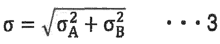

- According to the evaluation method of a sliding member, by evaluating in the evaluating step, the possibility of occurrence of a seizure between the first sliding face and the second sliding face based on the roughness parameter Rac in the
formula 1, the possibility of occurrence of a seizure can be easily evaluated. - It is to be noted that in the present invention, the "roughness projection apices" are determined by the following procedure based on a roughness curve with a measured length of 4.0 mm which is measured at a cut-off value of 0.25 mm according to JIS-B0601 (2013). Firstly, an average line of the roughness curve is set according to JIS-B0601 (2013), and with the average line as a reference, heights of measurement points above the average line are defined as positive values, while heights of measurement points below the average line are defined as negative values. An average value of the heights of all the measurement points having positive values is denoted by Thr0. Next, of the measurement points on the roughness curve, a measurement point which is higher than measurement points adjacent thereto on both sides and has a height greater than -Thr0 is assumed to be a temporary apex. Of measurement points between temporary apices adjacent to each other, a measurement point having a smallest height is defined as a valley. Then, for all the temporary apices, height differences between a temporary apex and left and right valleys adjacent to the temporary apex are respectively determined; in a case in which either of these height differences is less than 0.2 × Thr0, the corresponding temporary apex is excluded. As a result, remaining temporary apices are determined as roughness projection apices. It is to be noted that when straight lines are drawn toward a roughness projection apex from all the measurement points on a roughness curve which connects the roughness projection apex to a valley adjacent to the roughness projection apex, a measurement point having a largest gradient of the straight line is determined for each of the left and right sides of the roughness projection apex and defined as an end of the roughness projection apex.
- In the present invention, a "height of a roughness projection apex" refers to a height of a roughness projection apex with the above-mentioned average line as a reference. The "average value of the heights of the roughness projection apices" as referred to herein means an arithmetic mean value of the heights of all the roughness projection apices on the roughness curve. The "root mean square of the heights of the roughness projection apices" as referred to herein means a square root of the arithmetic mean of squares of the heights of the roughness projection apices relative to the average value of the heights of all the roughness projection apices on the roughness curve.
- In the present invention, the "radius of curvature of roughness projections" is calculated by the following procedure. Firstly, a roughness curve between both ends of each roughness projection apex is approximated by the method of least squares. Then, in a case in which a quadratic coefficient of a quadratic function obtained as a result of the approximation by the method of least squares is denoted by a, the radius of curvature of each roughness projection apex is calculated as -0.5/a. Furthermore, the "median of radius of curvature of roughness projections in an entirety of the first sliding face and the second sliding face" as referred to herein means a median of radius of curvature of all the roughness projection apices on the roughness curve of the first sliding face and the roughness curve of the second sliding face.
- In the present invention, the "roughness projection density per unit area" refers to a density calculated as (m/L)2 in a case in which a measured length of the roughness curve, i.e. a length of the horizontal axis of the roughness curve is denoted by L, and a number of roughness projection apices on the roughness curve is denoted by m.
- In the present invention, the "equivalent longitudinal elastic modulus" refers to a value of E [GPa] calculated according to the following formula 8 in a case in which a Poisson's ratio of the first sliding face is denoted by vA, a longitudinal elastic modulus of the first sliding face is denoted by EA [GPa], a Poisson's ratio of the second sliding face is denoted by vB, and a longitudinal elastic modulus of the second sliding face is denoted by EB [GPa].

- In the present invention, that "a sliding face having a lower hardness is defined as a mirror surface having no roughness projection" means that the average value of the heights of the roughness projection apices, the root mean square of the heights of the roughness projection apices, and the roughness projection density per unit area of the sliding face having a lower hardness are converted to 0, and the median of radius of curvature of roughness projections in the entirety of the first sliding face and the second sliding face is converted to a median of radius of curvature of roughness projections on the sliding face having a higher hardness.
- Hereinafter, embodiments of the present invention are described in detail with reference to the drawings.
- A sliding member in
FIG. 1 is, for example, a sliding member for ship which is disposed on a ship. The sliding member comprises: ashaft member 1 having a first slidingface 11; and a bearingmember 2 having a second slidingface 21 which slidably supports the first slidingface 11. The first slidingface 11 and the second slidingface 21 face each other. The second slidingface 21 surrounds an outer peripheral face of the first slidingface 11. A lubricatingliquid 3 is supplied between the first slidingface 11 and the second slidingface 21. - The
shaft member 1 is a rotating body which rotates in a circumferential direction with respect to the bearingmember 2. Theshaft member 1 is exemplified by a crankshaft, an intermediate shaft, a propulsion shaft, and the like for ship. Examples of a material of theshaft member 1 include carbon steel, low-alloy steel, and the like. - A shaft diameter d of the first sliding
face 11 is not particularly limited, and may be greater than or equal to 180 mm. Furthermore, the shaft diameter d of the first slidingface 11 may be greater than or equal to 280 mm, and may be greater than or equal to 360 mm. In theshaft member 1 having a large diameter in which the shaft diameter d of the first slidingface 11 is greater than or equal to the lower limit value, it may be desirable that the first slidingface 11 is manually polished. Even in such a case, the sliding member enables easy inhibition of a seizure between the first slidingface 11 and the second slidingface 21. - The upper limit of the shaft diameter d of the first sliding
face 11 is preferably 1,500 mm, more preferably 1,400 mm, and still more preferably 1,300 mm. When the shaft diameter d of the first slidingface 11 is greater than the upper limit value, the sliding member becomes too large, and a demand for reduction in device size may be contradicted. - The bearing
member 2 is exemplified by a crank bearing, an intermediate bearing, a propulsion bearing, and the like for ship. Examples of a material of the bearingmember 2 include white metal, trimetal, kelmet, aluminum alloy, and the like. - In the sliding member, the roughness parameter Rac which is calculated according to the following
formula 1 and relates to the first slidingface 11 and the second slidingface 21 is less than or equal to 0.276.
- In the formula 1, δ represents a value [µm] calculated according to the following formula 2 in a case in which an average value of heights of roughness projection apices of the first sliding face 11 is denoted by δA [µm], and an average value of heights of roughness projection apices of the second sliding face 21 is denoted by δB [µm]; σ represents a value [µm] calculated according to the following formula 3 in a case in which a root mean square of the heights of the roughness projection apices of the first sliding face 11 is denoted by σA [µm], and a root mean square of the heights of the roughness projection apices of the second sliding face 21 is denoted by σB [µm]; η represents a value [µm2] calculated according to the following formula 4 in a case in which a roughness projection density per unit area of the first sliding face 11 is denoted by ηA [µm-2], and a roughness projection density per unit area of the second sliding face 21 is denoted by ηB [µm-2]; β represents a median [µm] of radius of curvature of roughness projections in an entirety of the first sliding face 11 and the second sliding face 21; and E∗ represents an equivalent longitudinal elastic modulus [GPa] of the first sliding face 11 and the second sliding face 21.


- The upper limit of the roughness parameter Rac is preferably 0.185, and more preferably 0.141. When the roughness parameter Rac is greater than the upper limit, it may be difficult to inhibit a seizure between the first sliding
face 11 and the second slidingface 21. - The lower limit of β is not particularly limited, and may be, for example, greater than 51, may be greater than 55, and may be greater than 58. In the sliding member, the value of β is likely to be increased in the case in which the first sliding
face 11 manually polished. Even in such a case, the sliding member enables easy inhibition of a seizure between the first slidingface 11 and the second slidingface 21. - Meanwhile, the upper limit of β is preferably 338, more preferably 330, and still more preferably 320. When β is greater than the upper limit value, it may be difficult to inhibit a seizure between the first sliding
face 11 and the second slidingface 21. - It is preferred that δ is less than or equal to 0.232, and σ is less than or equal to 0.209. Setting δ and σ to be less than or equal to the respective upper limit values enables easy inhibition of a seizure between the first sliding
face 11 and the second slidingface 21. More specifically, the value of β is increased when the first slidingface 11 is manually polished; as a result, the value of the roughness parameter Rac in theformula 1 is likely to be increased. Even in such a case, by controlling δ and σ to be less than or equal to the respective upper limit values, the value of the roughness parameter Rac can be easily decreased. Thus, a seizure between the first slidingface 11 and the second slidingface 21 is easily inhibited. - The upper limit of δ is more preferably 0.181, and still more preferably 0.166. Meanwhile, the lower limit of δ is preferably 0.034, more preferably 0.040, and still more preferably 0.050. When δ is greater than the upper limit value, it may be difficult to inhibit a seizure between the first sliding
face 11 and the second slidingface 21. Conversely, when δ is less than the lower limit value, polishing other than the manual polishing is further required, and thus the production cost of the sliding member may be increased. - The upper limit of σ is more preferably 0.166, and still more preferably 0.130. The lower limit of σ is preferably 0.052, more preferably 0.060, and still more preferably 0.070. When σ is greater than the upper limit value, it may be difficult to inhibit a seizure between the first sliding
face 11 and the second slidingface 21. Conversely, when σ is less than the lower limit value, polishing other than the manual polishing is further required, and thus the production cost of the sliding member may be increased. - The first sliding
face 11 and the second slidingface 21 differ in hardness. For example, the hardness of the first slidingface 11 may be higher than the hardness of the second slidingface 21. In the sliding member, since the first slidingface 11 and the second slidingface 21 differ in hardness, in a case in which the first slidingface 11 comes into contact with the second slidingface 21, microscopic projections on a surface having a higher hardness of these sliding faces are likely to be maintained. On the other hand, a surface having a lower hardness of the first slidingface 11 and the second slidingface 21 is easily plastically deformed due to rotational contact between the sliding faces. Hence, of the first slidingface 11 and the second slidingface 21, the sliding face having a lower hardness can be regarded as a surface having substantially the same level of roughness projections as the sliding face having a higher hardness, or as a mirror surface having substantially no roughness projection. In other words, in calculating the roughness parameter Rac according to theformula 1, the average value of the heights of the roughness projection apices, the root mean square of the heights of the roughness projection apices, and the roughness projection density per unit area of the sliding face having a lower hardness of the first slidingface 11 and the second slidingface 21 may be converted to values of the sliding face having a higher hardness, and these values may be converted to 0. Furthermore, β may be converted to the median of radius of curvature of roughness projections on the sliding face having a higher hardness. By thus regarding, of the first slidingface 11 and the second slidingface 21, the sliding face having a lower hardness as a surface having the same level of roughness projections as the sliding face having a higher hardness, or as a mirror surface having no roughness projection, Rac in theformula 1 can be calculated more easily in consideration of future plastic deformation of the sliding face having a lower hardness. Furthermore, by thus calculating Rac, an effect of inhibiting a seizure between the first slidingface 11 and the second slidingface 21 is easily obtained in a case in which, of the first slidingface 11 and the second slidingface 21, the sliding face having a higher hardness is manually polished. It is to be noted that the "hardness" as referred to herein means a Brinell hardness as defined in JIS-Z2243 (2018). - A difference in hardness between the first sliding
face 11 and the second slidingface 21 is preferably large. The lower limit of the difference in hardness between the first slidingface 11 and the second slidingface 21 is preferably 100 HB, more preferably 130 HB, and still more preferably 150 HB. - The lubricating liquid 3 forms a lubricating film between the first sliding
face 11 and the second slidingface 21 to increase slipperiness between the first slidingface 11 and the second slidingface 21. The lubricatingliquid 3 is exemplified by a lubricating oil such as a paraffin base oil, seawater, and the like. - By forming the above-mentioned lubricating film, the lubricating
liquid 3 facilitates maintaining a space between the first slidingface 11 and the second slidingface 21 in a fluid lubrication state. The fluid lubrication state between the first slidingface 11 and the second slidingface 21 enables inhibition of a seizure between the first slidingface 11 and the second slidingface 21. It is to be noted that the "fluid lubrication state" as referred to herein means a state of fluid lubrication which is sorted using a Stribeck curve. - The sliding member enables inhibition of a seizure on the sliding face by controlling the roughness parameter Rac in the
formula 1 to be less than or equal to the above value. - In the sliding member, for example, in a case in which the
shaft member 1 is a crankshaft for ship, a crankpin is eccentric to a journal, and thus the dimension accuracy of the sliding face due to mechanical processing is likely to be insufficient. More specifically, for example, in a case in which the first slidingface 11 is provided on a peripheral face of the crankpin, manual polishing of the first slidingface 11 is likely to be required. The first slidingface 11 which has been manually polished may have an increased radius of curvature of roughness projections, and thus it may be likely that a seizure occurs on the first slidingface 11. In other words, in the case in which theshaft member 1 is a crankshaft for ship, the value of β is likely to be increased. Even in such a case, in the sliding member, other roughness parameters such as δ, σ, and the like are controlled such that the roughness parameter Rac in theformula 1 is less than or equal to the above value. Accordingly, even in the case in which theshaft member 1 is a crankshaft for ship, the sliding member enables appropriate inhibition of a seizure on the sliding face. - An example of a production method of the sliding member in
FIG. 1 is described with reference toFIG. 2 . The production method of the sliding member comprising: theshaft member 1 having the first slidingface 11; and the bearingmember 2 having the second slidingface 21 which slidably supports the first slidingface 11, wherein the first slidingface 11 and the second slidingface 21 differ in hardness, comprises: a smoothing step S1 of smoothing, of the first slidingface 11 and the second slidingface 21, the sliding face having a higher hardness. - The smoothing step S1 is performed after the
shaft member 1 and the bearingmember 2 are formed by mechanical processing. The dimension accuracy of theshaft member 1 and the bearingmember 2 after the mechanical processing may be insufficient, and thus manual polishing of the sliding face having a higher hardness of the first slidingface 11 and the second sliding face 21 (for example, the first slidingface 11 of the shaft member 1) may be required in order to improve the dimension accuracy. When the first slidingface 11 is manually polished, the radius of curvature of roughness projections on the first slidingface 11 is likely to be increased. More specifically, for example, in a case in which the value of β after the mechanical processing is within a range of greater than or equal to 23.78 and less than or equal to 51.00, the value of β after the manual polishing of the first slidingface 11 may be increased to be within a range of greater than or equal to 55.79 and less than or equal to 337.9. When the value of β is increased in this way, the roughness parameter Rac calculated according to theformula 1 is increased, and therefore a seizure is likely to occur between theshaft member 1 and the bearingmember 2. Thus, in the smoothing step S1, of the first slidingface 11 and the second slidingface 21, the sliding face having a higher hardness is smoothed such that the roughness parameter Rac calculated according to theformula 1 is less than or equal to 0.276. In other words, in the smoothing step S1, the values such as δ, σ, and the like of the sliding face having a higher hardness of the first slidingface 11 and the second slidingface 21 are decreased such that the roughness parameter Rac is less than or equal to 0.276 even in the case in which the value of σ is large. In the smoothing step S1, the sliding face is preferably manually polished. - In the production method of a sliding member, since the first sliding
face 11 and the second slidingface 21 differ in hardness, of the first slidingface 11 and the second slidingface 21, the sliding face having a lower hardness can be regarded as a surface having substantially the same level of roughness projections as the sliding face having a higher hardness, or as a mirror surface having substantially no roughness projection. In other words, in calculating the roughness parameter Rac according to theformula 1, the average value of the heights of the roughness projection apices, the root mean square of the heights of the roughness projection apices, and the roughness projection density per unit area of the sliding face having a lower hardness of the first slidingface 11 and the second slidingface 21 may be converted to values of the sliding face having a higher hardness, and these values may be converted to 0. Furthermore, β may be converted to the median of radius of curvature of roughness projections on the sliding face having a higher hardness. By thus regarding, of the first slidingface 11 and the second slidingface 21, the sliding face having a lower hardness as a surface having the same level of roughness projections as the sliding face having a higher hardness, or as a mirror surface having no roughness projection, Rac in theformula 1 can be calculated more easily. - In the smoothing step S1, at least one of the first sliding
face 11 and the second slidingface 21 is preferably polished such that the value of δ is less than or equal to 0.232 and the value of σ is less than or equal to 0.209. By polishing at least one of the first slidingface 11 and the second slidingface 21 such that δ and σ are less than or equal to the respective upper limit values, even in the case in which the value of β is large, the value of the roughness parameter Rac can be easily decreased. - A method of smoothing at least one of the first sliding
face 11 of theshaft member 1 and the second slidingface 21 is not particularly limited, and is exemplified by polishing of at least one of the first slidingface 11 and the second slidingface 21 with sandpaper, and the like. - In the case in which at least one of the first sliding
face 11 and the second slidingface 21 is polished with sandpaper, for example, sandpaper having a roughness of greater than or equal to 240 mesh is preferably used. By thus using sandpaper of an appropriate mesh, the values of δ and σ are easily controlled to be small, while the value of β is likely to be increased. As a result, a seizure between the first slidingface 11 and the second slidingface 21 is easily inhibited. - According to the production method of a sliding member, by controlling in the smoothing step S1, the roughness parameter Rac in the
formula 1 to be less than or equal to the above value, a sliding member which enables inhibition of a seizure on a sliding face can be produced. - An example of an evaluation method of the sliding member is described with reference to
FIG. 3 . The evaluation method of the sliding member comprising: the shaft member having the first sliding face; and the bearing member having the second sliding face which slidably supports the first sliding face, comprises: an evaluating step S1 of evaluating a possibility of occurrence of a seizure between the first sliding face and the second sliding face based on a roughness parameter Rac calculated according to the followingformula 1. The evaluation method is suitable for evaluating, whether a seizure occurs between the first slidingface 11 and the second slidingface 21 of the sliding member inFIG. 1 . In the evaluating step S1, a case in which the roughness parameter Rac is less than or equal to a threshold value is evaluated as a low possibility of occurrence of the seizure; conversely, a case in which the roughness parameter Rac is greater than the threshold value is evaluated as a high possibility of occurrence of the seizure.
- In the
formula 1, δ represents a value [µm] calculated according to the followingformula 2 in a case in which an average value of heights of roughness projection apices of the first sliding face is denoted by δA [µm], and an average value of heights of roughness projection apices of the second sliding face is denoted by δB [µm]; σ represents a value [µm] calculated according to the followingformula 3 in a case in which a root mean square of the heights of the roughness projection apices of the first sliding face is denoted by σA [µm], and a root mean square of the heights of the roughness projection apices of the second sliding face is denoted by σB [µm]; η represents a value [µm-2] calculated according to the following formula 4 in a case in which a roughness projection density per unit area of the first sliding face is denoted by ηA [µm-2], and a roughness projection density per unit area of the second sliding face is denoted by ηB [µm-2]; β represents a median [µm] of radius of curvature of roughness projections in an entirety of the first sliding face and the second sliding face; and E∗ represents an equivalent longitudinal elastic modulus [GPa] of the first sliding face and the second sliding face.


- The evaluating step S1 is performed after the shaft member and the bearing member are formed by mechanical processing. Furthermore, the evaluating step S1 may be performed after the first sliding face is brought into rotational contact with the second sliding face to a certain degree.
- The threshold value is preferably 0.276, more preferably 0.185, and still more preferably 0.141.
- In the evaluating step S1, in calculating the roughness parameter Rac according to the
formula 1, the average value of the heights of the roughness projection apices, the root mean square of the heights of the roughness projection apices, and the roughness projection density per unit area of the sliding face having a lower hardness of the first sliding face and the second sliding face may be converted to values of the sliding face having a higher hardness, and these values may be converted to 0. Furthermore, β may be converted to the median of radius of curvature of roughness projections on the sliding face having a higher hardness. By thus regarding, of the first sliding face and the second sliding face, the sliding face having a lower hardness as a surface having the same level of roughness projections as the sliding face having a higher hardness, or as a mirror surface having no roughness projection, Rac in theformula 1 can be calculated more easily. - According to the evaluation method of a sliding member, by evaluating in the evaluating step S1, the possibility of occurrence of a seizure between the first sliding face and the second sliding face based on the roughness parameter Rac in the
formula 1, the possibility of occurrence of a seizure can be easily evaluated. - The above-described embodiment does not limit the configuration of the present invention. Therefore, in the above-described embodiment, the components of each part of the above-described embodiment can be omitted, replaced, or added based on the description in the present specification and general technical knowledge, and such omission, replacement, or addition should be construed as falling within the scope of the present invention.
- For example, the sliding member may also adopt a configuration in which the lubricating liquid is not supplied between the first sliding face and the second sliding face.
- Furthermore, in the sliding member, even in the case in which the first sliding face and the second sliding face differ in hardness, the roughness parameter Rac may be calculated based on the shapes of the roughness projections on the respective sliding faces.
- Hereinafter, the present invention is described in detail by way of Examples; the present invention should not be construed as being limited to description in the Examples.
- By fixing a shaft member and a bearing member to a bearing lifetime tester available from KOBELCO MACHINERY ENGINEERING Co., Ltd., it was confirmed whether a seizure occurred between the shaft member and the bearing member. In the bearing lifetime tester, in a case in which a sliding part of the shaft member with respect to the bearing member on an outer peripheral face of the shaft member is defined as a first sliding face, and a sliding part of the bearing member with respect to the shaft member on an inner peripheral face of the bearing member is defined as a second sliding face, the shaft member was rotated while the first sliding face of the shaft member was pressed against the second sliding face of the bearing member with a constant load. In rotating the shaft member, a lubricating oil was supplied to the first sliding face of the shaft member by circulation oil supply at a supply temperature of 70 °C. Furthermore, at this time, the temperature [°C] was measured with a thermocouple equipped at a depth of 2 mm from the second sliding face of the bearing member, and this temperature was determined as a temperature of the lubricating oil.
- In No. 1, the shaft member was rotated under the following conditions. A load of the shaft member applied to the bearing member was set to 10 kN. A rotation speed of the shaft member was set to 3,000 rpm at the start of the rotation of the shaft member, and was decreased by 250 rpm in each 5 minutes. The rotation of the shaft member was terminated when the rotation speed of the shaft member reached 0 rpm, or when a seizure occurred between the shaft member and the bearing member. Table 1 shows results of confirming whether a seizure occurred between the shaft member and the bearing member. It is to be noted that the roughness parameter Rac [µm] in Table 1 was calculated according to the
formula 1 in such a manner that the average value of the heights of the roughness projection apices, the root mean square of the heights of the roughness projection apices, and the roughness projection density per unit area of the second sliding face were set to 0, and the median of radius of curvature of roughness projections in the entirety of the first sliding face and the second sliding face was converted to the median of radius of curvature of roughness projections on the first sliding face. Furthermore, an arithmetic mean roughness Ra [µm] and a protruding peak height Rpk [µm] in Table 1 are an arithmetic mean roughness Ra of the first sliding face as defined in JIS-B0601 (2013) and a protruding peak height Rpk of the first sliding face as defined in JIS-B0671-2 (2002), respectively. It is to be noted that the roughness parameter Rac, the arithmetic mean roughness Ra, and the protruding peak height Rpk in Table 1 were determined by averaging values calculated through a plurality of measurements. Furthermore, an oil film thickness h [mm] at a time of occurrence of the seizure in Table 1 was calculated using the Ertel-Grubin equation represented by the following formula 9. Here, γ [Pa·sec] represents a viscosity of the lubricating oil which is calculated from the temperature of the lubricating oil at the time of occurrence of the seizure; R [m] represents an equivalent radius calculated according to the following formula 10 from a radius R1 of the shaft member and a radius R2 of the bearing member; α [1/GPa] represents a viscosity-pressure coefficient of the lubricating oil; u [m/sec] represents a peripheral speed of the shaft member which is calculated from the rotation speed of the shaft member; and w [N/m] represents a load per unit contact length in a bearing width direction, the load per unit being determined by dividing the load of the shaft member applied to the bearing member by the bearing width. In the Examples, α was set to 0.02 to calculate the oil film thickness h at the time of occurrence of the seizure. The calculation methods of the roughness parameter Rac and the oil film thickness h at the time of occurrence of the seizure were similarly applied to No. 2 to No. 8 described later.

- In No. 1, carbon steel S45C as defined in JIS-G4051 (2016), which has a Young's modulus of 210,000 MPa, a Poisson's ratio of 0.3, a shaft diameter of the first sliding face of 39.96 mm, and a hardness of approximately 172 HB, was used as the shaft member. In No. 1, the first sliding face was manually polished after mechanical processing to adjust, for the first sliding face, the average value of the heights of the roughness projection apices to 0.074 µm, the root mean square of the heights of the roughness projection apices to 0.078 µm, the radius of curvature of roughness projections to 60.91 µm, and the roughness projection density per unit area to 0.0134 gm-2. It is to be noted that the average value of the heights of the roughness projection apices, the root mean square of the heights of the roughness projection apices, the radius of curvature of roughness projections, and the roughness projection density per unit area of the first sliding face were determined by averaging values calculated through a plurality of measurements. The calculation methods of the average value of the heights of the roughness projection apices, the root mean square of the heights of the roughness projection apices, the radius of curvature of roughness projections, and the roughness projection density per unit area of the first sliding face were similarly applied to No. 2 to No. 8 described later.
- In No. 1, white metal WJ2 as defined in JIS-H5401 (1958), which has a Young's modulus of 55,000 MPa, a Poisson's ratio of 0.33, a diameter of the second sliding face of 40.2 mm, a bearing width of 35 mm, and a hardness of approximately 27 HB, was used as the bearing member.
- In No. 1, "FBK oil RO32", available from ENEOS Corporation, which has a kinetic viscosity at 40 °C of 32.1 mm2/sec and a density at 15 °C of 0.871 g/cm3, was used as the lubricating oil.
- In No. 2, the shaft member was rotated under the following conditions using a shaft member below, a bearing member similar to that in No. 1, and a lubricating oil similar to that in No. 1. A load of the shaft member applied to the bearing member was set to 10 kN. The rotation speed of the shaft member was set to 3,000 rpm at the start of the rotation of the shaft member, and was decreased by 100 rpm in each 5 minutes. After the rotation speed of the shaft member reached less than or equal to 300 rpm, the rotation speed of the shaft member was decreased by 50 rpm in each 5 minutes. The rotation of the shaft member was terminated when the rotation speed of the shaft member reached 0 rpm, or when a seizure occurred between the shaft member and the bearing member. Table 1 shows results of confirming whether a seizure occurred between the shaft member and the bearing member.
- In No. 2, the first sliding face was manually polished after mechanical processing to adjust, for the first sliding face, the average value of the heights of the roughness projection apices to 0.166 µm, the root mean square of the heights of the roughness projection apices to 0.130 µm, the radius of curvature of roughness projections to 17.88 µm, and the roughness projection density per unit area to 0.0158 µm-2. In terms of the other points, the configuration was similar to that of the shaft member in No. 1.
- In No. 3, the first sliding face was manually polished after mechanical processing to adjust, for the first sliding face, the average value of the heights of the roughness projection apices to 0.181 µm, the root mean square of the heights of the roughness projection apices to 0.166 µm, the radius of curvature of roughness projections to 29.53 µm, and the roughness projection density per unit area to 0.0096 µm-2. In terms of the other points, the configuration was similar to that of No. 1, and the shaft member was rotated under conditions similar to those in No. 1. Table 1 shows results of confirming whether a seizure occurred.
- In No. 4, the first sliding face was manually polished after mechanical processing to adjust, for the first sliding face, the average value of the heights of the roughness projection apices to 0.232 µm, the root mean square of the heights of the roughness projection apices to 0.209 µm, the radius of curvature of roughness projections to 18.78 µm, and the roughness projection density per unit area to 0.0119 µm-2. In terms of the other points, the configuration was similar to that of No. 2, and the shaft member was rotated under conditions similar to those in No. 2. Table 1 shows results of confirming whether a seizure occurred.
- In No. 5, the first sliding face was manually polished after mechanical processing; the configuration was similar to that of No. 2 except that, for the first sliding face, the average value of the heights of the roughness projection apices was set to 0.272 µm, the root mean square of the heights of the roughness projection apices was set to 0.203 µm, the radius of curvature of roughness projections was set to 16.20 µm, and the roughness projection density per unit area was set to 0.0121 µm-2, and the shaft member was rotated under conditions similar to those in No. 2. Table 1 shows results of confirming whether a seizure occurred.
- In No. 6, the first sliding face was manually polished after mechanical processing; the configuration was similar to that of No. 2 except that, for the first sliding face, the average value of the heights of the roughness projection apices was set to 0.544 µm, the root mean square of the heights of the roughness projection apices was set to 0.320 µm, the radius of curvature of roughness projections was set to 9.40 µm, and the roughness projection density per unit area was set to 0.0075 µm-2, and the shaft member was rotated under conditions similar to those in No. 2. Table 1 shows results of confirming whether a seizure occurred.
- In No. 7, the first sliding face was manually polished after mechanical processing; the configuration was similar to that of No. 2 except that, for the first sliding face, the average value of the heights of the roughness projection apices was set to 0.634 µm, the root mean square of the heights of the roughness projection apices was set to 0.298 µm, the radius of curvature of roughness projections was set to 13.94 µm, and the roughness projection density per unit area was set to 0.0049 µm-2, and the shaft member was rotated under conditions similar to those in No. 2. Table 1 shows results of confirming whether a seizure occurred.
- In No. 8, the first sliding face was manually polished after mechanical processing; the configuration was similar to that of No. 1 except that, for the first sliding face, the average value of the heights of the roughness projection apices was set to 0.460 µm, the root mean square of the heights of the roughness projection apices was set to 0.534 µm, the radius of curvature of roughness projections was set to 18.94 µm, and the roughness projection density per unit area was set to 0.0055 µm-2, and the shaft member was rotated under conditions similar to those in No. 1. Table 1 shows results of confirming whether a seizure occurred.
Table 1 No. 1 No. 2 No. 3 No. 4 No. 5 No. 6 No. 7 No. 8 Roughness parameter Rac [µm] 0.067 0.141 0.185 0.276 0.283 0.439 0.452 0.795 Arithmetic mean roughness Ra [µm] 0.091 0.153 0.202 0.231 0.266 0.475 0.569 0.488 Protruding peak height Rpk [µm] 0.097 0.202 0.186 0.238 0.231 0.235 0.248 0.809 Seizure occurred? No No No No Yes Yes Yes Yes Rotation speed at time of occurrence of seizure [rpm] - - - - 270 500 500 500 Temperature at time of occurrence of seizure [°C] - - - - 71.5 78.7 73.5 93.7 Oil film thickness h at time of occurrence of seizure [mm] - - - - 0.326 0.441 0.491 0.771 - As seen from Table 1, a seizure is inhibited in No. 1 to No. 4 in which the roughness parameter Rac is less than or equal to 0.276. Furthermore, the roughness parameter Rac is positively correlated with the oil film thickness h at the time of occurrence of the seizure. The correlation between the roughness parameter Rac and the oil film thickness h at the time of occurrence of the seizure is higher than a correlation between the arithmetic mean roughness Ra and the oil film thickness h at the time of occurrence of the seizure and a correlation between the protruding peak height Rpk and the oil film thickness h at the time of occurrence of the seizure. This indicates that the roughness parameter Rac is a parameter suitable for evaluating the likelihood of occurrence of a seizure.
- It is to be noted that in the Examples, the carbon steel and the white metal WJ2 were used as the shaft member and the bearing member, respectively; however, it is considered that, for example, also in a case in which carbon steel S45C and an Al-Sn alloy are used as the shaft member and the bearing member, respectively, a seizure can be inhibited by satisfying the roughness parameter Rac of less than or equal to 0.276. A reason for this is as follows: the hardness after annealing of the carbon steel S45C as defined in JIS-G4051 (2016) is typically greater than or equal to 137 HB and less than or equal to 170 HB, whereas as defined in Table 2 of ISO 3547-4, the hardness of AlSn6Cu is greater than or equal to 35 HB and less than or equal to 45 HB and the hardness of AlSn20Cu is greater than or equal to 30 HB and less than or equal to 45 HB, and thus a difference in hardness between the carbon steel S45C and the Al-Sn alloy is approximately 100 HB. That is to say, the difference in hardness between the carbon steel S45C and the Al-Sn alloy is a value close to the difference in hardness between the carbon steel S45C and the white metal WJ2 in the Examples, and thus it is considered that Rac which is determined only by the roughness characteristics and material properties of the sliding faces also has a similar value.
- The sliding member according to the one aspect of the present invention enables inhibition of a seizure on the sliding face; thus, the sliding member can be applied to, for example, a crankshaft, an intermediate shaft, a propulsion shaft, and the like for ship.
-
- 1
- Shaft member
- 11
- First sliding face
- 2
- Bearing member
- 21
- Second sliding face
- 3
- Lubricating liquid
- d
- Shaft diameter of first sliding face
Claims (7)
- A sliding member comprising:a shaft member having a first sliding face; anda bearing member having a second sliding face which slidably supports the first sliding face, wherein,the first sliding face and the second sliding face differ in hardness, anda roughness parameter Rac calculated according to formula 1 is less than or equal to 0.276,
 wherein, in the formula 1, δ represents a value [µm] calculated according to formula 2 in a case in which an average value of heights of roughness projection apices of the first sliding face is denoted by δA [µm], and an average value of heights of roughness projection apices of the second sliding face is denoted by δB [µm]; σ represents a value [µm] calculated according to formula 3 in a case in which a root mean square of the heights of the roughness projection apices of the first sliding face is denoted by σA [µm], and a root mean square of the heights of the roughness projection apices of the second sliding face is denoted by σB [µm]; η represents a value [µm-2] calculated according to formula 4 in a case in which a roughness projection density per unit area of the first sliding face is denoted by ηA [µm-2], and a roughness projection density per unit area of the second sliding face is denoted by ηB [µm-2]; β represents a median [µm] of radius of curvature of roughness projections in an entirety of the first sliding face and the second sliding face; and E∗ represents an equivalent longitudinal elastic modulus [GPa] of the first sliding face and the second sliding face,


- The sliding member according to claim 1, wherein the roughness parameter Rac is calculated in such a manner that, of the first sliding face and the second sliding face, a sliding face having a lower hardness is defined as a mirror surface having no roughness projection.
- The sliding member according to claim 1 or 2, wherein a lubricating liquid is supplied between the first sliding face and the second sliding face.
- The sliding member according to claim 1 or 2, wherein a shaft diameter of the first sliding face of the shaft member is greater than or equal to 180 mm.
- The sliding member according to claim 1 or 2, whereinδ is less than or equal to 0.232, andσ is less than or equal to 0.209.
- A production method of a sliding member comprising: a shaft member having a first sliding face; and a bearing member having a second sliding face which slidably supports the first sliding face, wherein the first sliding face and the second sliding face differ in hardness, the production method comprising:
smoothing, of the first sliding face and the second sliding face, a sliding face having a higher hardness such that a roughness parameter Rac calculated according to formula 1 is less than or equal to 0.276,


- An evaluation method of a sliding member comprising: a shaft member having a first sliding face; and a bearing member having a second sliding face which slidably supports the first sliding face, the evaluation method comprising:
evaluating a possibility of occurrence of a seizure between the first sliding face and the second sliding face based on a roughness parameter Rac calculated according to formula 1,


Applications Claiming Priority (1)
| Application Number | Priority Date | Filing Date | Title |
|---|---|---|---|
| JP2021098028A JP7487146B2 (en) | 2021-06-11 | 2021-06-11 | SLIDING MEMBER, MANUFACTURING METHOD OF SLIDING MEMBER, AND EVALUATION METHOD OF SLIDING MEMBER |
Publications (2)
| Publication Number | Publication Date |
|---|---|
| EP4102087A1 true EP4102087A1 (en) | 2022-12-14 |
| EP4102087B1 EP4102087B1 (en) | 2026-02-25 |
Family
ID=81655012
Family Applications (1)
| Application Number | Title | Priority Date | Filing Date |
|---|---|---|---|
| EP22173518.6A Active EP4102087B1 (en) | 2021-06-11 | 2022-05-16 | Sliding member, production method of sliding member, and evaluation method of sliding member |
Country Status (5)
| Country | Link |
|---|---|
| EP (1) | EP4102087B1 (en) |
| JP (1) | JP7487146B2 (en) |
| CN (1) | CN115467895B (en) |
| ES (1) | ES3064581T3 (en) |
| FI (1) | FI4102087T3 (en) |
Cited By (1)
| Publication number | Priority date | Publication date | Assignee | Title |
|---|---|---|---|---|
| EP4145008A1 (en) * | 2021-09-07 | 2023-03-08 | Kabushiki Kaisha Kobe Seiko Sho (Kobe Steel, Ltd.) | Sliding member and method for manufacturing sliding member |
Citations (4)
| Publication number | Priority date | Publication date | Assignee | Title |
|---|---|---|---|---|
| US5161898A (en) * | 1991-07-05 | 1992-11-10 | Camco International Inc. | Aluminide coated bearing elements for roller cutter drill bits |
| JP2004116707A (en) | 2002-09-27 | 2004-04-15 | Nippon Piston Ring Co Ltd | Combined sliding member |
| US20200256277A1 (en) * | 2018-07-26 | 2020-08-13 | Tpr Co., Ltd. | Cast iron cylinder liner, and internal combustion engine |
| EP3767119A1 (en) * | 2018-03-12 | 2021-01-20 | Nissan Motor Co., Ltd. | Bearing member |
Family Cites Families (5)
| Publication number | Priority date | Publication date | Assignee | Title |
|---|---|---|---|---|
| DE19824310C1 (en) * | 1998-06-02 | 1999-08-12 | Fraunhofer Ges Forschung | Bearing surface for metal bearing |
| JP4462077B2 (en) * | 2005-03-15 | 2010-05-12 | トヨタ自動車株式会社 | Combination sliding member |
| CN101910653A (en) * | 2007-12-28 | 2010-12-08 | 日产自动车株式会社 | Sliding devices including plain bearings |
| WO2013146108A1 (en) * | 2012-03-27 | 2013-10-03 | 千住金属工業株式会社 | Sliding member |
| JPWO2016143741A1 (en) * | 2015-03-10 | 2017-12-21 | 住友重機械工業株式会社 | Sliding member, sliding mechanism, and manufacturing method of sliding member |
-
2021
- 2021-06-11 JP JP2021098028A patent/JP7487146B2/en active Active
-
2022
- 2022-05-16 FI FIEP22173518.6T patent/FI4102087T3/en active
- 2022-05-16 EP EP22173518.6A patent/EP4102087B1/en active Active
- 2022-05-16 ES ES22173518T patent/ES3064581T3/en active Active
- 2022-05-30 CN CN202210597649.0A patent/CN115467895B/en active Active
Patent Citations (4)
| Publication number | Priority date | Publication date | Assignee | Title |
|---|---|---|---|---|
| US5161898A (en) * | 1991-07-05 | 1992-11-10 | Camco International Inc. | Aluminide coated bearing elements for roller cutter drill bits |
| JP2004116707A (en) | 2002-09-27 | 2004-04-15 | Nippon Piston Ring Co Ltd | Combined sliding member |
| EP3767119A1 (en) * | 2018-03-12 | 2021-01-20 | Nissan Motor Co., Ltd. | Bearing member |
| US20200256277A1 (en) * | 2018-07-26 | 2020-08-13 | Tpr Co., Ltd. | Cast iron cylinder liner, and internal combustion engine |
Cited By (1)
| Publication number | Priority date | Publication date | Assignee | Title |
|---|---|---|---|---|
| EP4145008A1 (en) * | 2021-09-07 | 2023-03-08 | Kabushiki Kaisha Kobe Seiko Sho (Kobe Steel, Ltd.) | Sliding member and method for manufacturing sliding member |
Also Published As
| Publication number | Publication date |
|---|---|
| ES3064581T3 (en) | 2026-04-27 |
| CN115467895A (en) | 2022-12-13 |
| CN115467895B (en) | 2025-10-21 |
| JP2022189450A (en) | 2022-12-22 |
| EP4102087B1 (en) | 2026-02-25 |
| FI4102087T3 (en) | 2026-04-07 |
| JP7487146B2 (en) | 2024-05-20 |
Similar Documents
| Publication | Publication Date | Title |
|---|---|---|
| JP5057578B2 (en) | Thrust roller type thrust roller bearing | |
| JP4273462B2 (en) | Self-lubricating sliding part material and piston ring wire | |
| EP4102087B1 (en) | Sliding member, production method of sliding member, and evaluation method of sliding member | |
| Jamari et al. | Running-in analysis of transmission gear | |
| US12031577B2 (en) | Crankshaft and method of manufacturing the same | |
| US11739788B2 (en) | Crankshaft and method of manufacturing the same | |
| JP6965005B2 (en) | Conical roller bearing | |
| EP4130500B1 (en) | Bearing device and method for driving bearing device | |
| EP4130498B1 (en) | Sliding member and method for driving sliding member | |
| JP2009150508A (en) | Thrust roller bearing | |
| JP2009150507A (en) | Thrust roller bearing | |
| EP4145008B1 (en) | Sliding member and method for manufacturing sliding member | |
| JP2023021900A (en) | Bearing device and driving method of bearing device | |
| JP5876759B2 (en) | Gears with excellent tooth surface fatigue life | |
| Winkelmann et al. | Impact of isotropic superfinishing on contact and bending fatigue of carburized steel | |
| Alshareef | Investigation and Modeling of Ball-Burnishing Factors Affecting Residual Stress of AISI 8620 Steel | |
| RU2011499C1 (en) | Method for repairs of bearing assembly of boosted internal combustion engine crankshaft and sliding bearing shell for realization thereof | |
| JP2009168066A (en) | Thrust roller bearing | |
| Joshi et al. | Essential mechanical properties of work roll for effective rolling using 20 Hi-cold rolling mill | |
| Rave et al. | Tribological behavior of concave bronze surfaces textured by CNC micromachining | |
| Ishida et al. | Improvement of Seizure Properties on Edge Bell-Mouth Geometry of Journal Bearing | |
| WO2021220749A1 (en) | Indentation resistance measurement method, indentation resistance prediction method for rolling bearings, machining condition selection method, bearing material quality selection method, burnishing condition selection method, and bearing manufacturing method | |
| Asai et al. | Anti-Peeling Rolling Bearing with Manganase Phosphate Coating | |
| JP5014289B2 (en) | Combination of sliding materials | |
| Sroka et al. | Chemically Accelerated Vibratory Finishing for the Elimination of Wear and Pitting of Alloy Steel Gears |
Legal Events
| Date | Code | Title | Description |
|---|---|---|---|
| PUAI | Public reference made under article 153(3) epc to a published international application that has entered the european phase |
Free format text: ORIGINAL CODE: 0009012 |
|
| STAA | Information on the status of an ep patent application or granted ep patent |
Free format text: STATUS: REQUEST FOR EXAMINATION WAS MADE |
|
| 17P | Request for examination filed |
Effective date: 20220516 |
|
| AK | Designated contracting states |
Kind code of ref document: A1 Designated state(s): AL AT BE BG CH CY CZ DE DK EE ES FI FR GB GR HR HU IE IS IT LI LT LU LV MC MK MT NL NO PL PT RO RS SE SI SK SM TR |
|
| RBV | Designated contracting states (corrected) |
Designated state(s): AL AT BE BG CH CY CZ DE DK EE ES FI FR GB GR HR HU IE IS IT LI LT LU LV MC MK MT NL NO PL PT RO RS SE SI SK SM TR |
|
| STAA | Information on the status of an ep patent application or granted ep patent |
Free format text: STATUS: EXAMINATION IS IN PROGRESS |
|
| 17Q | First examination report despatched |
Effective date: 20231113 |
|
| GRAP | Despatch of communication of intention to grant a patent |
Free format text: ORIGINAL CODE: EPIDOSNIGR1 |
|
| STAA | Information on the status of an ep patent application or granted ep patent |
Free format text: STATUS: GRANT OF PATENT IS INTENDED |
|
| GRAJ | Information related to disapproval of communication of intention to grant by the applicant or resumption of examination proceedings by the epo deleted |
Free format text: ORIGINAL CODE: EPIDOSDIGR1 |
|
| STAA | Information on the status of an ep patent application or granted ep patent |
Free format text: STATUS: EXAMINATION IS IN PROGRESS |
|
| INTG | Intention to grant announced |
Effective date: 20250903 |
|
| GRAP | Despatch of communication of intention to grant a patent |
Free format text: ORIGINAL CODE: EPIDOSNIGR1 |
|
| STAA | Information on the status of an ep patent application or granted ep patent |
Free format text: STATUS: GRANT OF PATENT IS INTENDED |
|
| INTC | Intention to grant announced (deleted) | ||
| INTG | Intention to grant announced |
Effective date: 20251029 |
|
| P01 | Opt-out of the competence of the unified patent court (upc) registered |
Free format text: CASE NUMBER: UPC_APP_0014545_4102087/2025 Effective date: 20251124 |
|
| GRAS | Grant fee paid |
Free format text: ORIGINAL CODE: EPIDOSNIGR3 |
|
| GRAA | (expected) grant |
Free format text: ORIGINAL CODE: 0009210 |
|
| STAA | Information on the status of an ep patent application or granted ep patent |
Free format text: STATUS: THE PATENT HAS BEEN GRANTED |
|
| AK | Designated contracting states |
Kind code of ref document: B1 Designated state(s): AL AT BE BG CH CY CZ DE DK EE ES FI FR GB GR HR HU IE IS IT LI LT LU LV MC MK MT NL NO PL PT RO RS SE SI SK SM TR |
|
| REG | Reference to a national code |
Ref country code: CH Ref legal event code: F10 Free format text: ST27 STATUS EVENT CODE: U-0-0-F10-F00 (AS PROVIDED BY THE NATIONAL OFFICE) Effective date: 20260225 Ref country code: GB Ref legal event code: FG4D |
|
| REG | Reference to a national code |
Ref country code: DE Ref legal event code: R096 Ref document number: 602022030950 Country of ref document: DE |
|
| REG | Reference to a national code |
Ref country code: IE Ref legal event code: FG4D |
|
| REG | Reference to a national code |
Ref country code: FI Ref legal event code: FGE |
|
| REG | Reference to a national code |
Ref country code: ES Ref legal event code: FG2A Ref document number: 3064581 Country of ref document: ES Kind code of ref document: T3 Effective date: 20260427 |
|
| REG | Reference to a national code |
Ref country code: NL Ref legal event code: MP Effective date: 20260225 |
|
| PG25 | Lapsed in a contracting state [announced via postgrant information from national office to epo] |
Ref country code: RS Free format text: LAPSE BECAUSE OF FAILURE TO SUBMIT A TRANSLATION OF THE DESCRIPTION OR TO PAY THE FEE WITHIN THE PRESCRIBED TIME-LIMIT Effective date: 20260525 |
|
| PGFP | Annual fee paid to national office [announced via postgrant information from national office to epo] |
Ref country code: ES Payment date: 20260601 Year of fee payment: 5 |
|
| PG25 | Lapsed in a contracting state [announced via postgrant information from national office to epo] |
Ref country code: PL Free format text: LAPSE BECAUSE OF FAILURE TO SUBMIT A TRANSLATION OF THE DESCRIPTION OR TO PAY THE FEE WITHIN THE PRESCRIBED TIME-LIMIT Effective date: 20260225 |
|
| PG25 | Lapsed in a contracting state [announced via postgrant information from national office to epo] |
Ref country code: GR Free format text: LAPSE BECAUSE OF FAILURE TO SUBMIT A TRANSLATION OF THE DESCRIPTION OR TO PAY THE FEE WITHIN THE PRESCRIBED TIME-LIMIT Effective date: 20260526 |
|
| REG | Reference to a national code |
Ref country code: LT Ref legal event code: MG9D |
|
| PG25 | Lapsed in a contracting state [announced via postgrant information from national office to epo] |
Ref country code: LT Free format text: LAPSE BECAUSE OF FAILURE TO SUBMIT A TRANSLATION OF THE DESCRIPTION OR TO PAY THE FEE WITHIN THE PRESCRIBED TIME-LIMIT Effective date: 20260225 |
|
| PGFP | Annual fee paid to national office [announced via postgrant information from national office to epo] |
Ref country code: DE Payment date: 20260527 Year of fee payment: 5 |
|
| PGFP | Annual fee paid to national office [announced via postgrant information from national office to epo] |
Ref country code: NO Payment date: 20260408 Year of fee payment: 5 |
|
| PG25 | Lapsed in a contracting state [announced via postgrant information from national office to epo] |
Ref country code: AT Free format text: LAPSE BECAUSE OF FAILURE TO SUBMIT A TRANSLATION OF THE DESCRIPTION OR TO PAY THE FEE WITHIN THE PRESCRIBED TIME-LIMIT Effective date: 20260225 Ref country code: SE Free format text: LAPSE BECAUSE OF FAILURE TO SUBMIT A TRANSLATION OF THE DESCRIPTION OR TO PAY THE FEE WITHIN THE PRESCRIBED TIME-LIMIT Effective date: 20260225 |
|
| PGFP | Annual fee paid to national office [announced via postgrant information from national office to epo] |
Ref country code: FI Payment date: 20260421 Year of fee payment: 5 |
|
| REG | Reference to a national code |
Ref country code: AT Ref legal event code: MK05 Ref document number: 1891114 Country of ref document: AT Kind code of ref document: T Effective date: 20260225 |
|
| PG25 | Lapsed in a contracting state [announced via postgrant information from national office to epo] |
Ref country code: HR Free format text: LAPSE BECAUSE OF FAILURE TO SUBMIT A TRANSLATION OF THE DESCRIPTION OR TO PAY THE FEE WITHIN THE PRESCRIBED TIME-LIMIT Effective date: 20260225 |
|
| PG25 | Lapsed in a contracting state [announced via postgrant information from national office to epo] |
Ref country code: PT Free format text: LAPSE BECAUSE OF FAILURE TO SUBMIT A TRANSLATION OF THE DESCRIPTION OR TO PAY THE FEE WITHIN THE PRESCRIBED TIME-LIMIT Effective date: 20260625 Ref country code: IS Free format text: LAPSE BECAUSE OF FAILURE TO SUBMIT A TRANSLATION OF THE DESCRIPTION OR TO PAY THE FEE WITHIN THE PRESCRIBED TIME-LIMIT Effective date: 20260625 |
|
| PG25 | Lapsed in a contracting state [announced via postgrant information from national office to epo] |
Ref country code: NL Free format text: LAPSE BECAUSE OF FAILURE TO SUBMIT A TRANSLATION OF THE DESCRIPTION OR TO PAY THE FEE WITHIN THE PRESCRIBED TIME-LIMIT Effective date: 20260225 |
|
| PG25 | Lapsed in a contracting state [announced via postgrant information from national office to epo] |
Ref country code: LV Free format text: LAPSE BECAUSE OF FAILURE TO SUBMIT A TRANSLATION OF THE DESCRIPTION OR TO PAY THE FEE WITHIN THE PRESCRIBED TIME-LIMIT Effective date: 20260225 |
|
| PG25 | Lapsed in a contracting state [announced via postgrant information from national office to epo] |
Ref country code: BG Free format text: LAPSE BECAUSE OF FAILURE TO SUBMIT A TRANSLATION OF THE DESCRIPTION OR TO PAY THE FEE WITHIN THE PRESCRIBED TIME-LIMIT Effective date: 20260225 |