EP4102076A1 - Pump casing - Google Patents
Pump casing Download PDFInfo
- Publication number
- EP4102076A1 EP4102076A1 EP22177040.7A EP22177040A EP4102076A1 EP 4102076 A1 EP4102076 A1 EP 4102076A1 EP 22177040 A EP22177040 A EP 22177040A EP 4102076 A1 EP4102076 A1 EP 4102076A1
- Authority
- EP
- European Patent Office
- Prior art keywords
- passage portion
- pump
- pump casing
- discharge passage
- discharge
- Prior art date
- Legal status (The legal status is an assumption and is not a legal conclusion. Google has not performed a legal analysis and makes no representation as to the accuracy of the status listed.)
- Pending
Links
Images



Classifications
-
- F—MECHANICAL ENGINEERING; LIGHTING; HEATING; WEAPONS; BLASTING
- F04—POSITIVE - DISPLACEMENT MACHINES FOR LIQUIDS; PUMPS FOR LIQUIDS OR ELASTIC FLUIDS
- F04D—NON-POSITIVE-DISPLACEMENT PUMPS
- F04D13/00—Pumping installations or systems
- F04D13/12—Combinations of two or more pumps
- F04D13/14—Combinations of two or more pumps the pumps being all of centrifugal type
-
- F—MECHANICAL ENGINEERING; LIGHTING; HEATING; WEAPONS; BLASTING
- F04—POSITIVE - DISPLACEMENT MACHINES FOR LIQUIDS; PUMPS FOR LIQUIDS OR ELASTIC FLUIDS
- F04D—NON-POSITIVE-DISPLACEMENT PUMPS
- F04D15/00—Control, e.g. regulation, of pumps, pumping installations or systems
- F04D15/02—Stopping of pumps, or operating valves, on occurrence of unwanted conditions
- F04D15/029—Stopping of pumps, or operating valves, on occurrence of unwanted conditions for pumps operating in parallel
-
- F—MECHANICAL ENGINEERING; LIGHTING; HEATING; WEAPONS; BLASTING
- F04—POSITIVE - DISPLACEMENT MACHINES FOR LIQUIDS; PUMPS FOR LIQUIDS OR ELASTIC FLUIDS
- F04D—NON-POSITIVE-DISPLACEMENT PUMPS
- F04D29/00—Details, component parts, or accessories
- F04D29/40—Casings; Connections of working fluid
- F04D29/42—Casings; Connections of working fluid for radial or helico-centrifugal pumps
- F04D29/426—Casings; Connections of working fluid for radial or helico-centrifugal pumps especially adapted for liquid pumps
Definitions
- the present invention relates to a pump casing.
- a pump apparatus is conventionally used for various applications in various kinds of houses and in a site such as a factory.
- an inline pump in which a pump section and a motor section are integrated, and a suction port and a discharge port of a pump are arranged on the same line is widely used because the inline pump is easily attachable in a middle of a pipe.
- the inline pump is installed in a construction facility, it is desirable to avoid stoppage of liquid supply when one inline pump has failed or one inline pump is subjected to periodic inspection.
- twin pump in which two inline pumps are arranged in parallel, one suction port and one discharge port are connected to the two inline pumps, and the two inline pumps share one suction port and one discharge port. Note that, in the following, in a case where the two inline pumps do not share one suction port and one discharge port, namely, in a case where each of the two inline pumps includes one suction port and one discharge port, each of the pumps is called a single pump.
- twin pump In the case where the twin pump is installed, if trouble occurs on one of the pumps, or the like, parts other than a casing of the pump having the trouble are detached, and an upper part of the casing is covered with a blank flange.
- the parts other than the casing include an electric motor disposed on the upper part of the casing, a rotary shaft coupled to the electric motor, and an impeller fixed to the rotary shaft and housed in the casing.
- operation can be continued by the other pump during a pump maintenance period or during a period when a spare part for the failed pump is prepared.
- a pump manufacturer requires downsizing of devices to be incorporated in an own product in order to downsize the own product as much as possible.
- a length of a header pipe to branch a pipe into pipes for two single pumps or to merge pipes can be reduced as compared with a case where the two single pumps are arranged in parallel.
- a valve such as a check valve for backflow prevention is shared by the two pumps configuring the twin pump, which makes it possible to achieve space saving.
- the twin pump manufacturer can meet space saving required by a customer. Further, alternately operating the two pumps configuring the twin pump makes it possible to simply double the pump lifetime.
- a reference value is determined for performance difference between the two pumps configuring the twin pump. Further, positional relationship between the suction port and the discharge port, a distance between the suction port and the discharge port, and the like are preferably set to the same as those of the single pump in terms of installation and operation of the pump. Therefore, PTL 1 discloses a technique in which two pumps configuring a twin pump are rotated in directions opposite to each other, to suppress performance difference between the two pumps. In PTL 1, since the pumps rotated in the opposite directions are used, it is possible to minimize the performance difference. However, it is necessary to fabricate two types pumps different in structure, which disadvantageously increases design/manufacturing/management costs and stock.
- PTL 2 discloses a technique in which a passage is suitably designed to suppress performance difference between two pumps different in shape.
- rotary shafts of the two pumps are arranged such that the rotary shafts of the two pumps are located at positions symmetrical about a line connecting a center of a suction port and a center of a discharge port. Therefore, it is considered that efficiency of the pumps is sacrificed.
- An aspect of the present invention is made to solve such issues, and an object thereof is to provide a pump casing eliminating a disadvantage that the design/manufacturing/management costs are increased.
- a pump casing used for a pump apparatus to transfer a liquid includes: a first pump casing; a first suction passage portion connected to the first pump casing; a first discharge passage portion connected to the first pump casing; a second pump casing; a second suction passage portion connected to the second pump casing; a second discharge passage portion connected to the second pump casing; a suction branching portion connected to the first suction passage portion and the second suction passage portion; and a discharge merging portion connected to the first discharge passage portion and the second discharge passage portion, in which the first pump casing and the second pump casing have substantially a same shape, and the first discharge passage portion and the second discharge passage portion have substantially a same shape.
- the first pump casing and the second pump casing have substantially the same shape, and the first discharge passage portion and the second discharge passage portion have substantially the same shape. Therefore, an impeller, a casing, and the like configuring the pump, and the discharge passage portion can be made common to the two pumps.
- the two pumps can use a motor of the same rotation direction, which makes it possible to make a rotating body common to the two pumps. Accordingly, it is possible to provide the pump casing that eliminates a disadvantage of increase in design/manufacturing/management costs and a disadvantage of increase in stock.
- the first discharge passage portion and the first pump casing are separately independent of each other and/or the second discharge passage portion and the second pump casing are separately independent of each other.
- a cross-sectional shape of a passage of the first discharge passage portion at a connection portion between the first discharge passage portion and the discharge merging portion is a rectangular shape
- a cross-sectional shape of a passage of the second discharge passage portion at a connection portion between the second discharge passage portion and the discharge merging portion is a rectangular shape
- a pump apparatus includes: a first electric motor; a first rotary shaft coupled to the first electric motor; a first impeller fixed to the first rotary shaft and housed in the first pump casing; a second electric motor; a second rotary shaft coupled to the second electric motor; a second impeller fixed to the second rotary shaft and housed in the second pump casing; and the pump casing according to any one of the first to third aspects.
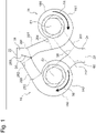
- Fig. 1 is a schematic view illustrating an embodiment of a pump casing 18 according to the present invention.
- the pump casing 18 is used for a pump apparatus 16 to transfer a liquid.
- One pump casing 18 includes a first pump casing 181, a first suction passage portion 201 connected to the first pump casing 181, and a first discharge passage portion 221 connected to the first pump casing 181.
- the pump casing 18 further includes a second pump casing 182, a second suction passage portion 202 connected to the second pump casing 182, and a second discharge passage portion 222 connected to the second pump casing 182.
- the pump casing 18 further includes a suction branching portion 24 connected to the first suction passage portion 201 and the second suction passage portion 202, and a discharge merging portion 26 connected to the first discharge passage portion 221 and the second discharge passage portion 222.
- the first pump casing 181, the first suction passage portion 201, the first discharge passage portion 221, the second pump casing 182, the second suction passage portion 202, the second discharge passage portion 222, the suction branching portion 24, and the discharge merging portion 26 are integrally formed as a casting. Some of these portions, for example, the first discharge passage portion 221, the second discharge passage portion 222, and the discharge merging portion 26 may be manufactured as castings other than the other portions. In other words, the first discharge passage portion 221 and the first pump casing 181 can be formed as an independent part, and/or the second discharge passage portion 222 and the second pump casing 182 can be formed as an independent part.
- the first pump casing 181 and the second pump casing 182 substantially have the same shape.
- the first discharge passage portion 221 and the second discharge passage portion 222 substantially have the same shape.
- the first pump casing and the second pump casing have substantially the same shape, and the first discharge passage portion and the second discharge passage portion have substantially the same shape. Therefore, an impeller, a casing, and the like configuring the pump, and the discharge passage portion can be made common to the two pumps.
- the two pumps can use a motor of the same rotation direction, which makes it possible to make a rotation body common to the two pumps.
- the pump casing that eliminates a disadvantage of increase in design/manufacturing/management costs and a disadvantage of increase in stock that occur in a case where the shapes are different. Since the shapes are the same as each other, design data and parts of one of the pumps can be diverted in a design stage, a manufacturing stage, and a maintenance stage, which makes it possible to reduce the cost in each of the stages.
- the suction branching portion 24 corresponds to a section from a suction port 20 to a part branched to the first suction passage portion 201 and the second suction passage portion 202. More specifically, the suction branching portion 24 corresponds to a section from the suction port 20 to a start end part 58 of the first suction passage portion 201, and a section from the suction port 20 to a start end part 60 of the second suction passage portion 202.
- the discharge merging portion 26 corresponds to a section from a part where the first discharge passage portion 221 and the second discharge passage portion 222 merge with each other to a discharge port 22.
- the discharge merging portion 26 corresponds to a section from a terminal end part 281 of the first discharge passage portion 221 to the discharge port 22, and a section from a terminal end part 282 of the second discharge passage portion 222 to the discharge port 22.
- the suction port 20 of the pump apparatus 16 is a connection portion between the pump apparatus 16 and a pipe (not illustrated) on a suction side of the pump apparatus 16.
- the discharge port 22 of the pump apparatus 16 is a connection portion between the pump apparatus 16 and a pipe (not illustrated) on a discharge side of the pump apparatus 16.
- the first discharge passage portion 221 and the first pump casing 181 can be formed as an independent part, and/or the second discharge passage portion 222 and the second pump casing 182 can be formed as an independent part.
- a boundary between the first discharge passage portion 221 and the first pump casing 181 is, for example, a connection portion 284 illustrated in Fig. 1 .
- a boundary between the second discharge passage portion 222 and the second pump casing 182 is, for example, a connection portion 285 illustrated in Fig. 1 .
- Positions of the connection portion 284 and the connection portion 285 are illustrative.
- the boundaries may be provided at positions close to the discharge port 22 more than the positions of the connection portion 284 and the connection portion 285, or the boundaries may be provided at positions far from the discharge port 22 more than the positions of the connection portion 284 and the connection portion 285.
- the pump apparatus 16 includes a first pump apparatus 161 and a second pump apparatus 162.
- the first pump apparatus 161 and the second pump apparatus 162 may have the same configuration or different configurations. In terms of compatibility, however, the first pump apparatus 161 and the second pump apparatus 162 preferably have the same configuration.
- the first pump apparatus 161 and the second pump apparatus 162 substantially have the same configuration.
- a first impeller 51, the first pump casing 181, and the first discharge passage portion 221 respectively have the same dimensional shapes as a second impeller 52, the second pump casing 182, and the second discharge passage portion 222.
- a rotation direction 54 of the first impeller 51 is the same as a rotation direction 56 of the second impeller 52.
- the dimensional shape of the first suction passage portion 201 and the dimensional shape of the second suction passage portion 202 are slightly different from each other.
- the first pump apparatus 161 and the second pump apparatus 162 are centrifugal pumps; however, the first pump apparatus 161 and the second pump apparatus 162 are not limited to the centrifugal pumps as long as the first pump apparatus 161 and the second pump apparatus 162 are non-positive displacement pumps.
- the first pump apparatus 161 and the second pump apparatus 162 may be turbine pumps, axial-flow pumps, or mixed flow pumps.
- Fig. 2 is a schematic view illustrating an embodiment of the first pump apparatus 161.
- the first pump apparatus 161 includes a first electric motor 101, a first rotary shaft 121 coupled to the first electric motor 101, and the first impeller 51 that is fixed to the first rotary shaft 121 and is housed in the first pump casing 181.
- the second pump apparatus 162 also have a second electric motor, a second rotary shaft coupled to the second electric motor, and the second impeller 52 that is fixed to the second rotary shaft and is housed in the second pump casing 182, as with the first pump apparatus 161.
- the first impeller 51 is a centrifugal impeller.
- the rotary shaft 121 is rotatably supported by a bearing (not illustrated).
- the rotary shaft 121 and the first impeller 51 are integrally rotatable.
- the rotary shaft 121 and the first impeller 51 are rotated by the electric motor 101.
- a liner ring 102 is disposed around a fluid inlet 51a of the first impeller 51.
- the liner ring 102 is fixed to the first pump casing 181.
- a casing cover 122 is disposed between the electric motor 101 and the first pump casing 181. An opening at an upper part of the first pump casing 181 is closed by the casing cover 122.
- the electric motor 101 is fixed to the casing cover 122.
- the first pump casing 181 and the casing cover 122 are formed as castings.
- a shaft sealing device 15 sealing a gap between the rotary shaft 121 and the casing cover 122 is disposed on a rear side of the first impeller 51.
- the shaft sealing device 15 is held by the casing cover 122. Examples of the shaft sealing device 15 include a mechanical seal.
- the blank flange (not illustrated) is disposed at a position of the casing cover 122 at maintenance or the like.
- the blank flange is attached by using screw holes 62 (see Fig. 3 ) circumferentially arranged for attachment of the casing cover 122.
- the blank flange has a disk shape, and includes, on an outer edge of the blank flange, attachment holes circumferentially arranged at positions corresponding to the screw holes 62.
- the pump casing 18 includes the suction branching portion 24 including the suction port 20, and the discharge merging portion 26 including the discharge port 22.
- the first impeller 51 is disposed inside the first pump casing 181.
- the suction port 20 and the discharge port 22 are arranged on one straight line.
- the pump apparatus 16 in which the suction port 20 and the discharge port 22 are arranged on one straight line is called an inline pump apparatus.
- two inline pumps are arranged in parallel, one suction port and one discharge port are connected to the two inline pumps, and the two inline pumps share one suction port and one discharge port. When the two inline pumps share one suction port and one discharge port, these pumps configure one twin pump as a whole.
- a difference between one inline pump as a twin pump and two inline pumps (two single pumps) arranged in parallel is described.
- discharge ports of the single pumps are connected to respective pipes on a discharge side, and the two pipes are then merged to form one pipe on a downstream side.
- one pipe is branched into two pipes, and the two pipes are connected to suction ports of the respective single pumps.
- twin pump two discharge passage portions are merged at the discharge merging portion 26 on the discharge side, and the merged passage portion is connected to a pipe at the discharge port 22 of the twin pump.
- a pipe is connected to the suction port 20 of the pump, and is then branched into two suction passage portions through the suction branching portion 24.
- the liquid flows into the pump casing 18 from the suction port 20. More specifically, the liquid flows into the first suction passage portion 201 from the suction port 20, and then flows into the fluid inlet 51a of the first impeller 51 through the first suction passage portion 201.
- the rotating first impeller 51 applies velocity energy to the liquid, and the velocity energy of the liquid flowing through the first pump casing 181 is converted into pressure.
- the pressurized liquid is discharged from the pump casing 18 through the discharge port 22.
- the discharge merging portion 26 includes an on-off valve 28.
- the on-off valve 28 closes the discharge passage portion connected to the stopped pump apparatus based on operation states of the first pump apparatus 161 and the second pump apparatus 162.
- the on-off valve 28 is moved to a position 282 illustrated by a dotted line by hydraulic pressure from the first discharge passage portion 221, to close the second discharge passage portion 222.
- the on-off valve 28 is moved to a position 281 illustrated by a dashed line by hydraulic pressure from the second discharge passage portion 222, to close the first discharge passage portion 221.
- the on-off valve 28 is moved to an intermediate position 283 illustrated by a solid line by hydraulic pressure from the first discharge passage portion 221 and hydraulic pressure from the second discharge passage portion 222.
- Figs. 3 to 5 each illustrate a configuration of the single pump casing 18.
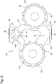
- Fig. 3 is a top view of the pump casing 18.
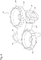
- Fig. 4 is a perspective view of the pump casing 18.
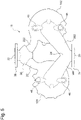
- Fig. 5 is a bottom view of the pump casing 18.
- Figs. 3 to 5 each illustrate the pump casing 18 in a state where the components other than the pump casing 18, namely, the first electric motor 101, the first rotary shaft 121, the first impeller 51, the second electric motor, the second rotary shaft, the second impeller 52, and the like are detached from the pump apparatus 16.
- the suction port 20 is provided in a suction flange 34.
- the suction flange 34 is to connect the pump casing 18 to a pipe.
- the discharge port 22 is provided in a discharge flange 36.
- the discharge flange 36 is to connect the pump casing 18 to a pipe.
- the pump casing 18 can include leg portions 46 and 48 provided in the first pump casing 181 and the second pump casing 182. The reason why the leg portions 46 and 48 are provided at these positions is because a bottom part of the first pump casing 181 and a bottom part of the second pump casing 182 are located at the lowest positions in the pump apparatus 16 as illustrated in Fig. 2 .
- a cross-sectional shape 64 of the passage of the first discharge passage portion 221 at the connection portion 281 between the first discharge passage portion 221 and the discharge merging portion 26 can be formed in a rectangular shape, and/or the cross-sectional shape 64 of the passage of the second discharge passage portion 222 at the connection portion 282 between the second discharge passage portion 222 and the discharge merging portion 26 can be formed in a rectangular shape.
- Fig. 6 is a diagram illustrating the terminal end part 282 (connection portion 282) of the second discharge passage portion 222 as viewed from a direction 66 illustrated in Fig. 3 .
- the cross-sectional shape 64 of the passage of the first discharge passage portion 221 at the terminal end part 281 and the cross-sectional shape 64 of the passage of the second discharge passage portion 222 at the terminal end part 282 are both formed in a rectangular shape.
- an outer shape of the second discharge passage portion 222 is a circular tube shape
- the cross-sectional shape of the passage inside the second discharge passage portion 222 is a circular shape.
- the outer shape of the second discharge passage portion 222 is changed from the circular tube shape to a rectangular tube shape from the connection portion 285 between the second pump casing 182 and the second discharge passage portion 222 toward the connection portion 282 between the discharge merging portion 26 and the second discharge passage portion 222.
- the cross-sectional shape of the passage inside the second discharge passage portion 222 is also changed from the circular shape to the rectangular shape.
- the shape of the first discharge passage portion 221 is also changed in a manner similar to the shape of the second discharge passage portion 222.
- Fig. 7 illustrates a case where a cross-sectional shape 68 of the inner diameter of the second discharge passage portion 222 connected to the discharge merging portion 26 is a circular shape.
- Fig. 7 is a diagram illustrating the terminal end part 282 of the second discharge passage portion 222 as viewed from the direction 66 in Fig. 3 in the case where the cross-sectional shape 68 of the inner diameter is the circular shape.
- Figs. 8 to 10 illustrate comparative examples of the present invention. These comparative examples are examples in which the first pump casing and the second pump casing do not have the same shape, or the first discharge passage portion and the second discharge passage portion do not have the same shape.
- Fig. 8 illustrates an example in which a first discharge passage portion 223 and a second discharge passage portion 224 do not have the same shape.
- a first pump casing 183 and a second pump casing 184 have the same shape.
- Rotary shafts 74 and 76 of the two pumps are arranged such that the rotary shafts 74 and 76 of the two pumps are located at positions symmetrical about a line 72 connecting a center of the suction port 20 and a center of the discharge port 22.
- rotary shafts 74 and 76 of the two pumps are arranged such that an intersection 84 between the line 72 and a line 78 connecting the rotary shaft 74 and the rotary shaft 76 is equally distanced from the center of the suction port 20 and the center of the discharge port 22.
- Fig. 8 illustrates that the intersection 84 is equally distanced from the center of the suction port 20 and the center of the discharge port 22. In other words, a distance 88 and a distance 90 are equal to each other.
- the discharge merging portion 26 is disposed so as to be symmetrical about the line 72 as in Fig. 3 .
- the first pump casing 183, the second pump casing 184, and the discharge merging portion 26 are arranged so as to have such symmetricity, the fluid flowing from the second discharge passage portion 224 on a left side into the discharge merging portion 26 is large in pressure loss inside the discharge merging portion 26.
- performance difference occurs between the right and left pumps.
- the second pump casing 184 on the left side is first disposed at a position where the pressure loss is small, and the discharge merging portion 26 and the first pump casing 183 are suitably disposed.
- the first pump casing 181 and the second pump casing 182 have substantially the same shape, and the first discharge passage portion 221 and the second discharge passage portion 222 have substantially the same shape.
- performance of the two pumps can be advantageously brought close to each other irrespective of a diameter and a shape of the passage.
- performance difference occurs between the two pumps with high possibility.
- an angle of the discharge merging portion 26 is inclined slightly, for example, by 15 degrees in a clockwise direction in Fig. 8 .
- a contact surface between the first discharge passage portion 223 and the discharge merging portion 26 is parallel.
- the fluid from the first discharge passage portion 223 flows into the connection portion 281 (see Fig. 1 ) in a perpendicular direction.
- the discharge merging portion 26 is not changed in shape but is slightly inclined in the clockwise direction.
- Inner walls 80 (see Fig. 3 together) of the discharge merging portion 26 illustrated in Fig. 8 indicate positions before the inclination, and inner walls 82 of the discharge merging portion 26 illustrated in Fig. 8 indicate positions after the inclination.
- the outer shape of the discharge merging portion 26 after the inclination is not illustrated in Fig. 8 for clarity of the drawing.
- the shape of the first discharge passage portion 223 is changed so as to match with the inclined discharge merging portion 26.
- the rotary shaft 74 and the rotary shaft 76 can be disposed so as to be equally distanced from the intersection 84 as a center of the whole apparatus. This stabilizes a centroid position.
- Fig. 8 The characteristics in Fig. 8 are organized as follows. (i) The rotary shafts 74 and 76 of the two pumps are located at the positions substantially symmetrical about the line 72 connecting the suction port 20 and the discharge port 22. (ii) The intersection 84 between the line 72 and the line 78 connecting the rotary shaft 74 and the rotary shaft 76 is substantially equally distanced from the suction port 20 and the discharge port 22.
- the discharge merging portion 26 is disposed at the position that is rotated from the position symmetrical about the line 72 in the clockwise direction (in other words, toward first pump casing 183 of first pump when pressure loss of first pump out of first pump and second pump is large) or in the counterclockwise direction (in other words, toward second pump casing 184 of second pump when pressure loss of second pump out of first pump and second pump is large) with a base part 92 of the discharge merging portion 26 as a rotation center.
- Fig. 9 illustrates a second comparative example.
- a first discharge passage portion 2231 is disposed substantially in parallel with the line 72 in Fig. 9 .
- a first pump casing 1831 is disposed at a position close to the line 72 more than the first pump casing 183 illustrated in Fig. 8 .
- the first pump casing 183 is moved toward the intersection 84 substantially in parallel with the line 78 connecting the rotary shaft 74 and the rotary shaft 76. Note that the first pump casing 183 and the first discharge passage portion 223 illustrated in Fig.
- FIG. 9 are the same as the first pump casing 183 and the first discharge passage portion 223 illustrated in Fig. 8 .
- the first pump casing 183 and the first discharge passage portion 223 illustrated in Fig. 8 are illustrated again in order to illustrate change of the first pump casing 183 and the first discharge passage portion 223.
- Disposing the first discharge passage portion 2231 substantially in parallel with the line 72 means that the arrangement of the first pump casing 1831 gets close to the arrangement of the above-described single pump. As a result, an angle of the passage of the fluid flowing from the first pump casing 1831 into the discharge merging portion 26 becomes gentle inside the discharge merging portion 26. Therefore, pressure loss of the first pump casing 1831 is reduced.
- the arrangement illustrated in Fig. 9 can be used.
- the characteristics in Fig. 9 are organized as follows.
- the first discharge passage portion 2231 is located at a position close to the line connecting the suction port 20 and the discharge port 22 more than the rotary shaft 74 of the first pump, and the first discharge passage portion 2231 is substantially parallel to the line connecting the suction port 20 and the discharge port 22.
- Fig. 10 illustrates a third comparative example.
- a first discharge passage portion 2232 is made longer than the second discharge passage portion 224 in Fig. 10 .
- the first discharge passage portion 223 and the first pump casing 183 illustrated in Fig. 10 are rotated around the rotary shaft 74 in the counterclockwise direction, and are then moved in a positive X direction and a positive Y direction such that an end part of the first discharge passage portion 223 is located at the position of the discharge merging portion 26.
- Fig. 10 illustrates a first pump casing 1832 and the first discharge passage portion 2232 that are the first discharge passage portion 223 and the first pump casing 183 rotated by 29 degrees in the counterclockwise direction and then moved in the positive X direction and the positive Y direction.
- first discharge passage portion 2232 is longer than the second discharge passage portion 224, it is possible to gently expand the diameter of the passage of the first discharge passage portion 2232 in a direction from the first pump casing 1832 toward the discharge merging portion 26, as compared with the second discharge passage portion 224.
- the first discharge passage portion 2232 is relatively small in an expansion amount of the diameter of the passage per unit length (in other words, expansion ratio). Therefore, pressure loss caused by abrupt expansion is reduced. As a result, performance of the first pump on the right side is improved to reduce the performance difference from the second pump on the left side.
- Fig. 10 The characteristics in Fig. 10 are organized as follows. (i) When pressure loss of the first pump out of the first pump and the second pump is large, the length of the first discharge passage portion 2232 is made longer than the length of the second discharge passage portion 224.
Landscapes
- Engineering & Computer Science (AREA)
- Mechanical Engineering (AREA)
- General Engineering & Computer Science (AREA)
- Structures Of Non-Positive Displacement Pumps (AREA)
Abstract
Description
- The present invention relates to a pump casing.
- A pump apparatus is conventionally used for various applications in various kinds of houses and in a site such as a factory. For example, an inline pump in which a pump section and a motor section are integrated, and a suction port and a discharge port of a pump are arranged on the same line is widely used because the inline pump is easily attachable in a middle of a pipe. In a case where the inline pump is installed in a construction facility, it is desirable to avoid stoppage of liquid supply when one inline pump has failed or one inline pump is subjected to periodic inspection.
- To avoid stoppage of liquid supply, a case where two inline pumps are arranged in parallel such that one of the inline pumps backs up the other inline pump can be seen in markets of various countries. There is a product that is called a twin pump in which two inline pumps are arranged in parallel, one suction port and one discharge port are connected to the two inline pumps, and the two inline pumps share one suction port and one discharge port. Note that, in the following, in a case where the two inline pumps do not share one suction port and one discharge port, namely, in a case where each of the two inline pumps includes one suction port and one discharge port, each of the pumps is called a single pump.
- In the case where the twin pump is installed, if trouble occurs on one of the pumps, or the like, parts other than a casing of the pump having the trouble are detached, and an upper part of the casing is covered with a blank flange. Examples of the parts other than the casing include an electric motor disposed on the upper part of the casing, a rotary shaft coupled to the electric motor, and an impeller fixed to the rotary shaft and housed in the casing. In the twin pump, operation can be continued by the other pump during a pump maintenance period or during a period when a spare part for the failed pump is prepared.
- It is desirable to provide a pump requiring a small space and having a long lifetime. A pump manufacturer requires downsizing of devices to be incorporated in an own product in order to downsize the own product as much as possible. To meet the request, in a case of the twin pump, a length of a header pipe to branch a pipe into pipes for two single pumps or to merge pipes can be reduced as compared with a case where the two single pumps are arranged in parallel. Further, a valve such as a check valve for backflow prevention is shared by the two pumps configuring the twin pump, which makes it possible to achieve space saving. As a result, the twin pump manufacturer can meet space saving required by a customer. Further, alternately operating the two pumps configuring the twin pump makes it possible to simply double the pump lifetime.
- A reference value is determined for performance difference between the two pumps configuring the twin pump. Further, positional relationship between the suction port and the discharge port, a distance between the suction port and the discharge port, and the like are preferably set to the same as those of the single pump in terms of installation and operation of the pump. Therefore, PTL 1 discloses a technique in which two pumps configuring a twin pump are rotated in directions opposite to each other, to suppress performance difference between the two pumps. In PTL 1, since the pumps rotated in the opposite directions are used, it is possible to minimize the performance difference. However, it is necessary to fabricate two types pumps different in structure, which disadvantageously increases
design/manufacturing/management costs and stock. - PTL 2 discloses a technique in which a passage is suitably designed to suppress performance difference between two pumps different in shape. In PTL 2, rotary shafts of the two pumps are arranged such that the rotary shafts of the two pumps are located at positions symmetrical about a line connecting a center of a suction port and a center of a discharge port. Therefore, it is considered that efficiency of the pumps is sacrificed.
- PTL 1: International Publication No.
WO 2018/137019 - PTL 2:
European Patent Laid-Open No. 2161455A - An aspect of the present invention is made to solve such issues, and an object thereof is to provide a pump casing eliminating a disadvantage that the design/manufacturing/management costs are increased.
- To solve the above-described issues, according to a first aspect, a pump casing used for a pump apparatus to transfer a liquid, includes: a first pump casing; a first suction passage portion connected to the first pump casing; a first discharge passage portion connected to the first pump casing; a second pump casing; a second suction passage portion connected to the second pump casing; a second discharge passage portion connected to the second pump casing; a suction branching portion connected to the first suction passage portion and the second suction passage portion; and a discharge merging portion connected to the first discharge passage portion and the second discharge passage portion, in which the first pump casing and the second pump casing have substantially a same shape, and the first discharge passage portion and the second discharge passage portion have substantially a same shape.
- In the present aspect, the first pump casing and the second pump casing have substantially the same shape, and the first discharge passage portion and the second discharge passage portion have substantially the same shape. Therefore, an impeller, a casing, and the like configuring the pump, and the discharge passage portion can be made common to the two pumps. The two pumps can use a motor of the same rotation direction, which makes it possible to make a rotating body common to the two pumps. Accordingly, it is possible to provide the pump casing that eliminates a disadvantage of increase in design/manufacturing/management costs and a disadvantage of increase in stock.
- According to a second aspect, in the pump casing according to the first aspect, the first discharge passage portion and the first pump casing are separately independent of each other and/or the second discharge passage portion and the second pump casing are separately independent of each other.
- According to a third aspect, in the pump casing according to the first or second aspect, a cross-sectional shape of a passage of the first discharge passage portion at a connection portion between the first discharge passage portion and the discharge merging portion is a rectangular shape, and/or a cross-sectional shape of a passage of the second discharge passage portion at a connection portion between the second discharge passage portion and the discharge merging portion is a rectangular shape.
- According to a fourth aspect, a pump apparatus includes: a first electric motor; a first rotary shaft coupled to the first electric motor; a first impeller fixed to the first rotary shaft and housed in the first pump casing; a second electric motor; a second rotary shaft coupled to the second electric motor; a second impeller fixed to the second rotary shaft and housed in the second pump casing; and the pump casing according to any one of the first to third aspects.
-
Fig. 1 is a schematic view illustrating an embodiment of a pump casing; -
Fig. 2 is a schematic view illustrating an embodiment of a first pump apparatus; -
Fig. 3 is a top view of the pump casing; -
Fig. 4 is a perspective view of the pump casing; -
Fig. 5 is a bottom view of the pump casing; -
Fig. 6 is a diagram illustrating a terminal end part of a second discharge passage portion as viewed from adirection 66 illustrated inFig. 3 ; -
Fig. 7 is a diagram illustrating the terminal end portion of the second discharge passage portion as viewed from thedirection 66 illustrated inFig. 3 in a case where a cross-section of an inner diameter is a circular shape; -
Fig. 8 is a diagram illustrating an example in which a first discharge passage portion and the second discharge passage portion do not have the same shape; -
Fig. 9 is a diagram illustrating another example in which the first discharge passage portion and the second discharge passage portion do not have the same shape; and -
Fig. 10 is a diagram illustrating still another example in which the first discharge passage portion and the second discharge passage portion do not have the same shape. - Some embodiments of the present invention are described below with reference to drawings. Note that, in the following embodiments, the same or equivalent members are denoted by the same reference numerals, and repetitive descriptions are omitted in some cases. Further, characteristics described in each of the embodiments are applicable to another embodiment without conflicting with each other.
-
Fig. 1 is a schematic view illustrating an embodiment of apump casing 18 according to the present invention. Thepump casing 18 is used for apump apparatus 16 to transfer a liquid. Onepump casing 18 includes afirst pump casing 181, a firstsuction passage portion 201 connected to thefirst pump casing 181, and a firstdischarge passage portion 221 connected to thefirst pump casing 181. Thepump casing 18 further includes asecond pump casing 182, a secondsuction passage portion 202 connected to thesecond pump casing 182, and a seconddischarge passage portion 222 connected to thesecond pump casing 182. - The
pump casing 18 further includes asuction branching portion 24 connected to the firstsuction passage portion 201 and the secondsuction passage portion 202, and adischarge merging portion 26 connected to the firstdischarge passage portion 221 and the seconddischarge passage portion 222. Thefirst pump casing 181, the firstsuction passage portion 201, the firstdischarge passage portion 221, thesecond pump casing 182, the secondsuction passage portion 202, the seconddischarge passage portion 222, thesuction branching portion 24, and thedischarge merging portion 26 are integrally formed as a casting. Some of these portions, for example, the firstdischarge passage portion 221, the seconddischarge passage portion 222, and thedischarge merging portion 26 may be manufactured as castings other than the other portions. In other words, the firstdischarge passage portion 221 and thefirst pump casing 181 can be formed as an independent part, and/or the seconddischarge passage portion 222 and thesecond pump casing 182 can be formed as an independent part. - The
first pump casing 181 and thesecond pump casing 182 substantially have the same shape. The firstdischarge passage portion 221 and the seconddischarge passage portion 222 substantially have the same shape. In the present embodiment, the first pump casing and the second pump casing have substantially the same shape, and the first discharge passage portion and the second discharge passage portion have substantially the same shape. Therefore, an impeller, a casing, and the like configuring the pump, and the discharge passage portion can be made common to the two pumps. The two pumps can use a motor of the same rotation direction, which makes it possible to make a rotation body common to the two pumps. Accordingly, it is possible to provide the pump casing that eliminates a disadvantage of increase in design/manufacturing/management costs and a disadvantage of increase in stock that occur in a case where the shapes are different. Since the shapes are the same as each other, design data and parts of one of the pumps can be diverted in a design stage, a manufacturing stage, and a maintenance stage, which makes it possible to reduce the cost in each of the stages. - Since the shapes are the same as each other, it is possible to easily settle performance difference of the two pumps within an ISO reference value, as compared with an existing technique. Various ISO reference values are present depending on a type of the pump and a grade of the pump. For example, a flow rate difference (m3/minute) between the two pumps is within ±9%, and a total pump head difference (m) is within ±7%. Examples of an ISO standard include ISO 9906. Note that ISO 9906 is illustrative, and the present embodiment can adapt a similar standard other than ISO 9906.
- The
suction branching portion 24 corresponds to a section from asuction port 20 to a part branched to the firstsuction passage portion 201 and the secondsuction passage portion 202. More specifically, thesuction branching portion 24 corresponds to a section from thesuction port 20 to astart end part 58 of the firstsuction passage portion 201, and a section from thesuction port 20 to astart end part 60 of the secondsuction passage portion 202. Thedischarge merging portion 26 corresponds to a section from a part where the firstdischarge passage portion 221 and the seconddischarge passage portion 222 merge with each other to adischarge port 22. More specifically, thedischarge merging portion 26 corresponds to a section from aterminal end part 281 of the firstdischarge passage portion 221 to thedischarge port 22, and a section from aterminal end part 282 of the seconddischarge passage portion 222 to thedischarge port 22. Thesuction port 20 of thepump apparatus 16 is a connection portion between thepump apparatus 16 and a pipe (not illustrated) on a suction side of thepump apparatus 16. Thedischarge port 22 of thepump apparatus 16 is a connection portion between thepump apparatus 16 and a pipe (not illustrated) on a discharge side of thepump apparatus 16. - As described above, the first
discharge passage portion 221 and thefirst pump casing 181 can be formed as an independent part, and/or the seconddischarge passage portion 222 and thesecond pump casing 182 can be formed as an independent part. In the case where the firstdischarge passage portion 221 and thefirst pump casing 181 are formed as an independent part, a boundary between the firstdischarge passage portion 221 and thefirst pump casing 181 is, for example, aconnection portion 284 illustrated inFig. 1 . In the case where the seconddischarge passage portion 222 and thesecond pump casing 182 are formed as an independent part, a boundary between the seconddischarge passage portion 222 and thesecond pump casing 182 is, for example, aconnection portion 285 illustrated inFig. 1 . Positions of theconnection portion 284 and theconnection portion 285 are illustrative. The boundaries may be provided at positions close to thedischarge port 22 more than the positions of theconnection portion 284 and theconnection portion 285, or the boundaries may be provided at positions far from thedischarge port 22 more than the positions of theconnection portion 284 and theconnection portion 285. - The
pump apparatus 16 includes afirst pump apparatus 161 and asecond pump apparatus 162. Thefirst pump apparatus 161 and thesecond pump apparatus 162 may have the same configuration or different configurations. In terms of compatibility, however, thefirst pump apparatus 161 and thesecond pump apparatus 162 preferably have the same configuration. In the present embodiment, thefirst pump apparatus 161 and thesecond pump apparatus 162 substantially have the same configuration. In other words, afirst impeller 51, thefirst pump casing 181, and the firstdischarge passage portion 221 respectively have the same dimensional shapes as asecond impeller 52, thesecond pump casing 182, and the seconddischarge passage portion 222. Arotation direction 54 of thefirst impeller 51 is the same as arotation direction 56 of thesecond impeller 52. On the other hand, the dimensional shape of the firstsuction passage portion 201 and the dimensional shape of the secondsuction passage portion 202 are slightly different from each other. - In the present embodiment, the
first pump apparatus 161 and thesecond pump apparatus 162 are centrifugal pumps; however, thefirst pump apparatus 161 and thesecond pump apparatus 162 are not limited to the centrifugal pumps as long as thefirst pump apparatus 161 and thesecond pump apparatus 162 are non-positive displacement pumps. In other words, thefirst pump apparatus 161 and thesecond pump apparatus 162 may be turbine pumps, axial-flow pumps, or mixed flow pumps. - Since the
first pump apparatus 161 and thesecond pump apparatus 162 substantially have the same configuration, the configuration of thefirst pump apparatus 161 is described with reference toFig. 2. Fig. 2 is a schematic view illustrating an embodiment of thefirst pump apparatus 161. Thefirst pump apparatus 161 includes a firstelectric motor 101, a firstrotary shaft 121 coupled to the firstelectric motor 101, and thefirst impeller 51 that is fixed to the firstrotary shaft 121 and is housed in thefirst pump casing 181. - Although not illustrated, the
second pump apparatus 162 also have a second electric motor, a second rotary shaft coupled to the second electric motor, and thesecond impeller 52 that is fixed to the second rotary shaft and is housed in thesecond pump casing 182, as with thefirst pump apparatus 161. - In the
first pump apparatus 161, thefirst impeller 51 is a centrifugal impeller. Therotary shaft 121 is rotatably supported by a bearing (not illustrated). Therotary shaft 121 and thefirst impeller 51 are integrally rotatable. Therotary shaft 121 and thefirst impeller 51 are rotated by theelectric motor 101. Aliner ring 102 is disposed around afluid inlet 51a of thefirst impeller 51. Theliner ring 102 is fixed to thefirst pump casing 181. - A
casing cover 122 is disposed between theelectric motor 101 and thefirst pump casing 181. An opening at an upper part of thefirst pump casing 181 is closed by thecasing cover 122. Theelectric motor 101 is fixed to thecasing cover 122. Thefirst pump casing 181 and thecasing cover 122 are formed as castings. Ashaft sealing device 15 sealing a gap between therotary shaft 121 and thecasing cover 122 is disposed on a rear side of thefirst impeller 51. Theshaft sealing device 15 is held by thecasing cover 122. Examples of theshaft sealing device 15 include a mechanical seal. The blank flange (not illustrated) is disposed at a position of thecasing cover 122 at maintenance or the like. The blank flange is attached by using screw holes 62 (seeFig. 3 ) circumferentially arranged for attachment of thecasing cover 122. The blank flange has a disk shape, and includes, on an outer edge of the blank flange, attachment holes circumferentially arranged at positions corresponding to the screw holes 62. - The
pump casing 18 includes thesuction branching portion 24 including thesuction port 20, and thedischarge merging portion 26 including thedischarge port 22. Thefirst impeller 51 is disposed inside thefirst pump casing 181. Thesuction port 20 and thedischarge port 22 are arranged on one straight line. Thepump apparatus 16 in which thesuction port 20 and thedischarge port 22 are arranged on one straight line is called an inline pump apparatus. In the present embodiment, two inline pumps are arranged in parallel, one suction port and one discharge port are connected to the two inline pumps, and the two inline pumps share one suction port and one discharge port. When the two inline pumps share one suction port and one discharge port, these pumps configure one twin pump as a whole. - A difference between one inline pump as a twin pump and two inline pumps (two single pumps) arranged in parallel is described. In the two single pumps arranged in parallel, discharge ports of the single pumps are connected to respective pipes on a discharge side, and the two pipes are then merged to form one pipe on a downstream side. Further, on a suction side, one pipe is branched into two pipes, and the two pipes are connected to suction ports of the respective single pumps. In contrast, in the twin pump, two discharge passage portions are merged at the
discharge merging portion 26 on the discharge side, and the merged passage portion is connected to a pipe at thedischarge port 22 of the twin pump. Further, on the suction side of the twin pump, a pipe is connected to thesuction port 20 of the pump, and is then branched into two suction passage portions through thesuction branching portion 24. - When the
electric motor 101 rotates thefirst impeller 51, the liquid flows into thepump casing 18 from thesuction port 20. More specifically, the liquid flows into the firstsuction passage portion 201 from thesuction port 20, and then flows into thefluid inlet 51a of thefirst impeller 51 through the firstsuction passage portion 201. The rotatingfirst impeller 51 applies velocity energy to the liquid, and the velocity energy of the liquid flowing through thefirst pump casing 181 is converted into pressure. The pressurized liquid is discharged from thepump casing 18 through thedischarge port 22. - Various methods of operating the
first pump apparatus 161 and thesecond pump apparatus 162 are usable. A method of operating only one of thefirst pump apparatus 161 and thesecond pump apparatus 162 and stopping the other pump apparatus, or a method of operating both of thefirst pump apparatus 161 and thesecond pump apparatus 162 at the same time is usable. As illustrated inFig. 1 , thedischarge merging portion 26 includes an on-offvalve 28. The on-offvalve 28 closes the discharge passage portion connected to the stopped pump apparatus based on operation states of thefirst pump apparatus 161 and thesecond pump apparatus 162. - For example, when the
first pump apparatus 161 operates and thesecond pump apparatus 162 stops, the on-offvalve 28 is moved to aposition 282 illustrated by a dotted line by hydraulic pressure from the firstdischarge passage portion 221, to close the seconddischarge passage portion 222. When thesecond pump apparatus 162 operates and thefirst pump apparatus 161 stops, the on-offvalve 28 is moved to aposition 281 illustrated by a dashed line by hydraulic pressure from the seconddischarge passage portion 222, to close the firstdischarge passage portion 221. When thefirst pump apparatus 161 and thesecond pump apparatus 162 both operate at the same time, the on-offvalve 28 is moved to anintermediate position 283 illustrated by a solid line by hydraulic pressure from the firstdischarge passage portion 221 and hydraulic pressure from the seconddischarge passage portion 222. -
Figs. 3 to 5 each illustrate a configuration of thesingle pump casing 18.Fig. 3 is a top view of thepump casing 18.Fig. 4 is a perspective view of thepump casing 18.Fig. 5 is a bottom view of thepump casing 18.Figs. 3 to 5 each illustrate thepump casing 18 in a state where the components other than thepump casing 18, namely, the firstelectric motor 101, the firstrotary shaft 121, thefirst impeller 51, the second electric motor, the second rotary shaft, thesecond impeller 52, and the like are detached from thepump apparatus 16. Thesuction port 20 is provided in asuction flange 34. Thesuction flange 34 is to connect thepump casing 18 to a pipe. Thedischarge port 22 is provided in adischarge flange 36. Thedischarge flange 36 is to connect thepump casing 18 to a pipe. - The
pump casing 18 can includeleg portions first pump casing 181 and thesecond pump casing 182. The reason why theleg portions first pump casing 181 and a bottom part of thesecond pump casing 182 are located at the lowest positions in thepump apparatus 16 as illustrated inFig. 2 . - As illustrated in
Fig. 6 , across-sectional shape 64 of the passage of the firstdischarge passage portion 221 at theconnection portion 281 between the firstdischarge passage portion 221 and thedischarge merging portion 26 can be formed in a rectangular shape, and/or thecross-sectional shape 64 of the passage of the seconddischarge passage portion 222 at theconnection portion 282 between the seconddischarge passage portion 222 and thedischarge merging portion 26 can be formed in a rectangular shape.Fig. 6 is a diagram illustrating the terminal end part 282 (connection portion 282) of the seconddischarge passage portion 222 as viewed from adirection 66 illustrated inFig. 3 . In the present embodiment, thecross-sectional shape 64 of the passage of the firstdischarge passage portion 221 at theterminal end part 281 and thecross-sectional shape 64 of the passage of the seconddischarge passage portion 222 at theterminal end part 282 are both formed in a rectangular shape. - At the
connection portion 285, an outer shape of the seconddischarge passage portion 222 is a circular tube shape, and the cross-sectional shape of the passage inside the seconddischarge passage portion 222 is a circular shape. The outer shape of the seconddischarge passage portion 222 is changed from the circular tube shape to a rectangular tube shape from theconnection portion 285 between thesecond pump casing 182 and the seconddischarge passage portion 222 toward theconnection portion 282 between thedischarge merging portion 26 and the seconddischarge passage portion 222. At this time, the cross-sectional shape of the passage inside the seconddischarge passage portion 222 is also changed from the circular shape to the rectangular shape. The shape of the firstdischarge passage portion 221 is also changed in a manner similar to the shape of the seconddischarge passage portion 222. - Since the cross-section of an inner diameter of the second
discharge passage portion 222 connected to thedischarge merging portion 26 is formed in the rectangular shape, it is possible to reduce pressure loss inside thedischarge merging portion 26. For comparison,Fig. 7 illustrates a case where across-sectional shape 68 of the inner diameter of the seconddischarge passage portion 222 connected to thedischarge merging portion 26 is a circular shape.Fig. 7 is a diagram illustrating theterminal end part 282 of the seconddischarge passage portion 222 as viewed from thedirection 66 inFig. 3 in the case where thecross-sectional shape 68 of the inner diameter is the circular shape. In comparison between thecross-sectional shape 64 inFig. 6 and thecross-sectional shape 68 inFig. 7 , in the case of thecross-sectional shape 64, a dead space inside thedischarge merging portion 26 is reduced, and the pressure loss inside thedischarge merging portion 26 is reduced. In other words, when the cross-sectional shape is the rectangular shape, a dead space of a hatchedportion 70 is reduced, and backflow and friction inside thedischarge merging portion 26 are reduced to reduce the pressure loss. - Next,
Figs. 8 to 10 illustrate comparative examples of the present invention. These comparative examples are examples in which the first pump casing and the second pump casing do not have the same shape, or the first discharge passage portion and the second discharge passage portion do not have the same shape.Fig. 8 illustrates an example in which a firstdischarge passage portion 223 and a seconddischarge passage portion 224 do not have the same shape. Afirst pump casing 183 and asecond pump casing 184 have the same shape.Rotary shafts rotary shafts line 72 connecting a center of thesuction port 20 and a center of thedischarge port 22. Further, therotary shafts intersection 84 between theline 72 and aline 78 connecting therotary shaft 74 and therotary shaft 76 is equally distanced from the center of thesuction port 20 and the center of thedischarge port 22.Fig. 8 illustrates that theintersection 84 is equally distanced from the center of thesuction port 20 and the center of thedischarge port 22. In other words, adistance 88 and adistance 90 are equal to each other. - The
discharge merging portion 26 is disposed so as to be symmetrical about theline 72 as inFig. 3 . In a case where thefirst pump casing 183, thesecond pump casing 184, and thedischarge merging portion 26 are arranged so as to have such symmetricity, the fluid flowing from the seconddischarge passage portion 224 on a left side into thedischarge merging portion 26 is large in pressure loss inside thedischarge merging portion 26. As a result, performance difference occurs between the right and left pumps. As countermeasures, the second pump casing 184 on the left side is first disposed at a position where the pressure loss is small, and thedischarge merging portion 26 and thefirst pump casing 183 are suitably disposed. - In
Fig. 3 described above, as the countermeasures, thefirst pump casing 181 and thesecond pump casing 182 have substantially the same shape, and the firstdischarge passage portion 221 and the seconddischarge passage portion 222 have substantially the same shape. When the shape of one of the members is diverted to the shape of the other member, performance of the two pumps can be advantageously brought close to each other irrespective of a diameter and a shape of the passage. When the two pumps each having the passage are changed in design, performance difference occurs between the two pumps with high possibility. - As countermeasures against the issue that the pressure loss is large on the left side, an angle of the
discharge merging portion 26 is inclined slightly, for example, by 15 degrees in a clockwise direction inFig. 8 . A contact surface between the firstdischarge passage portion 223 and thedischarge merging portion 26 is parallel. In other words, the fluid from the firstdischarge passage portion 223 flows into the connection portion 281 (seeFig. 1 ) in a perpendicular direction. Thedischarge merging portion 26 is not changed in shape but is slightly inclined in the clockwise direction. Inner walls 80 (seeFig. 3 together) of thedischarge merging portion 26 illustrated inFig. 8 indicate positions before the inclination, andinner walls 82 of thedischarge merging portion 26 illustrated inFig. 8 indicate positions after the inclination. The outer shape of thedischarge merging portion 26 after the inclination is not illustrated inFig. 8 for clarity of the drawing. Along with the inclination of thedischarge merging portion 26, the shape of the firstdischarge passage portion 223 is changed so as to match with the inclineddischarge merging portion 26. As advantages of the countermeasures inFig. 8 , therotary shaft 74 and therotary shaft 76 can be disposed so as to be equally distanced from theintersection 84 as a center of the whole apparatus. This stabilizes a centroid position. - The characteristics in
Fig. 8 are organized as follows. (i) Therotary shafts line 72 connecting thesuction port 20 and thedischarge port 22. (ii) Theintersection 84 between theline 72 and theline 78 connecting therotary shaft 74 and therotary shaft 76 is substantially equally distanced from thesuction port 20 and thedischarge port 22. (iii) Thedischarge merging portion 26 is disposed at the position that is rotated from the position symmetrical about theline 72 in the clockwise direction (in other words, towardfirst pump casing 183 of first pump when pressure loss of first pump out of first pump and second pump is large) or in the counterclockwise direction (in other words, toward second pump casing 184 of second pump when pressure loss of second pump out of first pump and second pump is large) with a base part 92 of thedischarge merging portion 26 as a rotation center. -
Fig. 9 illustrates a second comparative example. As countermeasures against the issue described with reference toFig. 8 , a firstdischarge passage portion 2231 is disposed substantially in parallel with theline 72 inFig. 9 . To dispose the firstdischarge passage portion 2231 substantially in parallel with theline 72, for example, afirst pump casing 1831 is disposed at a position close to theline 72 more than thefirst pump casing 183 illustrated inFig. 8 . To dispose thefirst pump casing 1831 at the position close to theline 72, for example, thefirst pump casing 183 is moved toward theintersection 84 substantially in parallel with theline 78 connecting therotary shaft 74 and therotary shaft 76. Note that thefirst pump casing 183 and the firstdischarge passage portion 223 illustrated inFig. 9 are the same as thefirst pump casing 183 and the firstdischarge passage portion 223 illustrated inFig. 8 . InFigs. 9 and10 , thefirst pump casing 183 and the firstdischarge passage portion 223 illustrated inFig. 8 are illustrated again in order to illustrate change of thefirst pump casing 183 and the firstdischarge passage portion 223. - Disposing the first
discharge passage portion 2231 substantially in parallel with theline 72 means that the arrangement of thefirst pump casing 1831 gets close to the arrangement of the above-described single pump. As a result, an angle of the passage of the fluid flowing from thefirst pump casing 1831 into thedischarge merging portion 26 becomes gentle inside thedischarge merging portion 26. Therefore, pressure loss of thefirst pump casing 1831 is reduced. In a case where the pump performance by thefirst pump casing 183 and the firstdischarge passage portion 223 on the right side is largely different from the pump performance by thesecond pump casing 184 and the seconddischarge passage portion 224 on the left side, the arrangement illustrated inFig. 9 can be used. - The characteristics in
Fig. 9 are organized as follows. In a case where the pressure loss of the first pump out of the first pump and the second pump is large, the firstdischarge passage portion 2231 is located at a position close to the line connecting thesuction port 20 and thedischarge port 22 more than therotary shaft 74 of the first pump, and the firstdischarge passage portion 2231 is substantially parallel to the line connecting thesuction port 20 and thedischarge port 22. -
Fig. 10 illustrates a third comparative example. As the countermeasures against the issue described with reference toFig. 8 , a firstdischarge passage portion 2232 is made longer than the seconddischarge passage portion 224 inFig. 10 . To make the firstdischarge passage portion 2232 longer than the seconddischarge passage portion 224, for example, the firstdischarge passage portion 223 and thefirst pump casing 183 illustrated inFig. 10 are rotated around therotary shaft 74 in the counterclockwise direction, and are then moved in a positive X direction and a positive Y direction such that an end part of the firstdischarge passage portion 223 is located at the position of thedischarge merging portion 26.Fig. 10 illustrates afirst pump casing 1832 and the firstdischarge passage portion 2232 that are the firstdischarge passage portion 223 and thefirst pump casing 183 rotated by 29 degrees in the counterclockwise direction and then moved in the positive X direction and the positive Y direction. - Since the first
discharge passage portion 2232 is longer than the seconddischarge passage portion 224, it is possible to gently expand the diameter of the passage of the firstdischarge passage portion 2232 in a direction from thefirst pump casing 1832 toward thedischarge merging portion 26, as compared with the seconddischarge passage portion 224. The firstdischarge passage portion 2232 is relatively small in an expansion amount of the diameter of the passage per unit length (in other words, expansion ratio). Therefore, pressure loss caused by abrupt expansion is reduced. As a result, performance of the first pump on the right side is improved to reduce the performance difference from the second pump on the left side. - The characteristics in
Fig. 10 are organized as follows. (i) When pressure loss of the first pump out of the first pump and the second pump is large, the length of the firstdischarge passage portion 2232 is made longer than the length of the seconddischarge passage portion 224. - Although the exemplary embodiments of the present invention are described above, the above-described embodiments of the present invention are to facilitate understanding of the present invention, and do not limit the present invention. Needless to say, the present invention can be modified and improved without departing from the spirit of the present invention, and includes equivalents thereof. Further, the components described in the claims and the specification can be optionally combined or omitted within a range where at least a part of the above-described issues is solved or within a range where at least a part of the effects is achieved.
- 16
- Pump apparatus
- 18
- Pump casing
- 20
- Suction port
- 22
- Discharge port
- 24
- Suction branching portion
- 26
- Discharge merging portion
- 28
- On-off valve
- 34
- Suction flange
- 36
- Discharge flange
- 51
- First impeller
- 52
- Second impeller
- 101
- Electric motor
- 101
- First electric motor
- 121
- Rotary shaft
- 121
- First rotary shaft
- 161
- First pump apparatus
- 162
- Second pump apparatus
- 181
- Pump casing
- 181
- First pump casing
- 182
- Second pump casing
- 201
- First suction passage portion
- 202
- Second suction passage portion
- 221
- First discharge passage portion
- 222
- Second discharge passage portion
Claims (4)
- A pump casing used for a pump apparatus to transfer a liquid, the pump casing comprising:a first pump casing;a first suction passage portion connected to the first pump casing;a first discharge passage portion connected to the first pump casing;a second pump casing;a second suction passage portion connected to the second pump casing;a second discharge passage portion connected to the second pump casing;a suction branching portion connected to the first suction passage portion and the second suction passage portion; anda discharge merging portion connected to the first discharge passage portion and the second discharge passage portion, whereinthe first pump casing and the second pump casing have substantially a same shape, andthe first discharge passage portion and the second discharge passage portion have substantially a same shape.
- The pump casing according to claim 1, wherein the first discharge passage portion and the first pump casing are separately independent of each other and/or the second discharge passage portion and the second pump casing are separately independent of each other.
- The pump casing according to claim 1 or 2, wherein a cross-sectional shape of a passage of the first discharge passage portion at a connection portion between the first discharge passage portion and the discharge merging portion is a rectangular shape, and/or a cross-sectional shape of a passage of the second discharge passage portion at a connection portion between the second discharge passage portion and the discharge merging portion is a rectangular shape.
- A pump apparatus, comprising:a first electric motor;a first rotary shaft coupled to the first electric motor;a first impeller fixed to the first rotary shaft and housed in the first pump casing;a second electric motor;a second rotary shaft coupled to the second electric motor;a second impeller fixed to the second rotary shaft and housed in the second pump casing; andthe pump casing according to any one of claims 1 to 3.
Applications Claiming Priority (1)
| Application Number | Priority Date | Filing Date | Title |
|---|---|---|---|
| JP2021095049A JP2022187176A (en) | 2021-06-07 | 2021-06-07 | pump casing |
Publications (1)
| Publication Number | Publication Date |
|---|---|
| EP4102076A1 true EP4102076A1 (en) | 2022-12-14 |
Family
ID=81877752
Family Applications (1)
| Application Number | Title | Priority Date | Filing Date |
|---|---|---|---|
| EP22177040.7A Pending EP4102076A1 (en) | 2021-06-07 | 2022-06-02 | Pump casing |
Country Status (2)
| Country | Link |
|---|---|
| EP (1) | EP4102076A1 (en) |
| JP (1) | JP2022187176A (en) |
Cited By (1)
| Publication number | Priority date | Publication date | Assignee | Title |
|---|---|---|---|---|
| LU503228B1 (en) | 2022-12-21 | 2024-06-21 | Wilo Se | Double pump with insulating cover and associated assembly procedure |
Citations (5)
| Publication number | Priority date | Publication date | Assignee | Title |
|---|---|---|---|---|
| CN2434454Y (en) * | 2000-07-18 | 2001-06-13 | 上海凯泉泵业(集团)有限公司 | Single-stage single-sucking vertical split centrifugal pump set |
| EP2161455A1 (en) | 2008-09-04 | 2010-03-10 | Grundfos Management A/S | Double pump |
| DE102014006258A1 (en) * | 2014-04-30 | 2015-11-05 | Wilo Se | Method for controlling a pump system and regulated pump system |
| WO2018137019A1 (en) | 2017-01-27 | 2018-08-02 | S. A. Armstrong Limited | Dual body variable duty performance optimizing pump unit |
| WO2020113113A1 (en) * | 2018-11-28 | 2020-06-04 | Bjm Pumps Llc | In-line pumping apparatus, system and method for increasing liquid flow in gravity networks |
-
2021
- 2021-06-07 JP JP2021095049A patent/JP2022187176A/en active Pending
-
2022
- 2022-06-02 EP EP22177040.7A patent/EP4102076A1/en active Pending
Patent Citations (5)
| Publication number | Priority date | Publication date | Assignee | Title |
|---|---|---|---|---|
| CN2434454Y (en) * | 2000-07-18 | 2001-06-13 | 上海凯泉泵业(集团)有限公司 | Single-stage single-sucking vertical split centrifugal pump set |
| EP2161455A1 (en) | 2008-09-04 | 2010-03-10 | Grundfos Management A/S | Double pump |
| DE102014006258A1 (en) * | 2014-04-30 | 2015-11-05 | Wilo Se | Method for controlling a pump system and regulated pump system |
| WO2018137019A1 (en) | 2017-01-27 | 2018-08-02 | S. A. Armstrong Limited | Dual body variable duty performance optimizing pump unit |
| WO2020113113A1 (en) * | 2018-11-28 | 2020-06-04 | Bjm Pumps Llc | In-line pumping apparatus, system and method for increasing liquid flow in gravity networks |
Cited By (2)
| Publication number | Priority date | Publication date | Assignee | Title |
|---|---|---|---|---|
| LU503228B1 (en) | 2022-12-21 | 2024-06-21 | Wilo Se | Double pump with insulating cover and associated assembly procedure |
| EP4390140A1 (en) | 2022-12-21 | 2024-06-26 | Wilo Se | Double pump with insulating liner and related assembly method |
Also Published As
| Publication number | Publication date |
|---|---|
| JP2022187176A (en) | 2022-12-19 |
Similar Documents
| Publication | Publication Date | Title |
|---|---|---|
| US10605270B2 (en) | Side-channel blower for an internal combustion engine, comprising a wide interrupting gap | |
| CN107842507B (en) | Gear-driven flow-through pitot tube pump | |
| EP2520804A1 (en) | Pump impeller and submersible pump having such pump impeller | |
| JPH0468480B2 (en) | ||
| CN102135100B (en) | Centrifugal pump assembly | |
| JP5546469B2 (en) | Multistage turbine impeller pump assembly | |
| JP2016031064A (en) | Multiple stage pump | |
| JP2012184758A (en) | Rotary machine | |
| GB2255591A (en) | Pump seal. | |
| US4097186A (en) | Multi-stage ring type centrifugal pumps with inducer means | |
| CN102135103A (en) | Refrigerant pump assembly | |
| JP2022187176A (en) | pump casing | |
| EP4102078A2 (en) | Discharge merging portion, pump casing, and pump apparatus | |
| EP4102077A1 (en) | Pump casing | |
| US11378096B2 (en) | Centrifugal compressor | |
| JP2019044659A (en) | Centrifugal compressor | |
| CN108779784A (en) | Multi-stage axial compressors and gas turbines | |
| JP6758358B2 (en) | pump | |
| CN112283120A (en) | Water pump module | |
| EP3828417B1 (en) | Bridged stage piece | |
| US11739750B2 (en) | Gear pump | |
| JP3059575B2 (en) | Sheet metal inline pump | |
| EP0408992B1 (en) | Rotating fluid machine for reversible operation from turbine to pump and vice-versa | |
| WO2025135121A1 (en) | Fluid machine and thermal cycling system | |
| KR101818038B1 (en) | Centrifugal pump |
Legal Events
| Date | Code | Title | Description |
|---|---|---|---|
| PUAI | Public reference made under article 153(3) epc to a published international application that has entered the european phase |
Free format text: ORIGINAL CODE: 0009012 |
|
| STAA | Information on the status of an ep patent application or granted ep patent |
Free format text: STATUS: THE APPLICATION HAS BEEN PUBLISHED |
|
| AK | Designated contracting states |
Kind code of ref document: A1 Designated state(s): AL AT BE BG CH CY CZ DE DK EE ES FI FR GB GR HR HU IE IS IT LI LT LU LV MC MK MT NL NO PL PT RO RS SE SI SK SM TR |
|
| STAA | Information on the status of an ep patent application or granted ep patent |
Free format text: STATUS: REQUEST FOR EXAMINATION WAS MADE |
|
| 17P | Request for examination filed |
Effective date: 20230614 |
|
| RBV | Designated contracting states (corrected) |
Designated state(s): AL AT BE BG CH CY CZ DE DK EE ES FI FR GB GR HR HU IE IS IT LI LT LU LV MC MK MT NL NO PL PT RO RS SE SI SK SM TR |
|
| RAP3 | Party data changed (applicant data changed or rights of an application transferred) |
Owner name: EBARA CORPORATION |
|
| STAA | Information on the status of an ep patent application or granted ep patent |
Free format text: STATUS: EXAMINATION IS IN PROGRESS |
|
| 17Q | First examination report despatched |
Effective date: 20240523 |
|
| GRAP | Despatch of communication of intention to grant a patent |
Free format text: ORIGINAL CODE: EPIDOSNIGR1 |
|
| STAA | Information on the status of an ep patent application or granted ep patent |
Free format text: STATUS: GRANT OF PATENT IS INTENDED |
|
| INTG | Intention to grant announced |
Effective date: 20260123 |