EP4102074A1 - Scroll compressor - Google Patents
Scroll compressor Download PDFInfo
- Publication number
- EP4102074A1 EP4102074A1 EP21751392.8A EP21751392A EP4102074A1 EP 4102074 A1 EP4102074 A1 EP 4102074A1 EP 21751392 A EP21751392 A EP 21751392A EP 4102074 A1 EP4102074 A1 EP 4102074A1
- Authority
- EP
- European Patent Office
- Prior art keywords
- orbiting
- scroll
- bearing
- tapered shape
- eccentric shaft
- Prior art date
- Legal status (The legal status is an assumption and is not a legal conclusion. Google has not performed a legal analysis and makes no representation as to the accuracy of the status listed.)
- Granted
Links
Images




Classifications
-
- F—MECHANICAL ENGINEERING; LIGHTING; HEATING; WEAPONS; BLASTING
- F04—POSITIVE - DISPLACEMENT MACHINES FOR LIQUIDS; PUMPS FOR LIQUIDS OR ELASTIC FLUIDS
- F04C—ROTARY-PISTON, OR OSCILLATING-PISTON, POSITIVE-DISPLACEMENT MACHINES FOR LIQUIDS; ROTARY-PISTON, OR OSCILLATING-PISTON, POSITIVE-DISPLACEMENT PUMPS
- F04C18/00—Rotary-piston pumps specially adapted for elastic fluids
- F04C18/02—Rotary-piston pumps specially adapted for elastic fluids of arcuate-engagement type, i.e. with circular translatory movement of co-operating members, each member having the same number of teeth or tooth-equivalents
- F04C18/0207—Rotary-piston pumps specially adapted for elastic fluids of arcuate-engagement type, i.e. with circular translatory movement of co-operating members, each member having the same number of teeth or tooth-equivalents both members having co-operating elements in spiral form
- F04C18/0215—Rotary-piston pumps specially adapted for elastic fluids of arcuate-engagement type, i.e. with circular translatory movement of co-operating members, each member having the same number of teeth or tooth-equivalents both members having co-operating elements in spiral form where only one member is moving
-
- F—MECHANICAL ENGINEERING; LIGHTING; HEATING; WEAPONS; BLASTING
- F04—POSITIVE - DISPLACEMENT MACHINES FOR LIQUIDS; PUMPS FOR LIQUIDS OR ELASTIC FLUIDS
- F04C—ROTARY-PISTON, OR OSCILLATING-PISTON, POSITIVE-DISPLACEMENT MACHINES FOR LIQUIDS; ROTARY-PISTON, OR OSCILLATING-PISTON, POSITIVE-DISPLACEMENT PUMPS
- F04C29/00—Component parts, details or accessories of pumps or pumping installations, not provided for in groups F04C18/00 - F04C28/00
- F04C29/0042—Driving elements, brakes, couplings, transmissions specially adapted for pumps
- F04C29/005—Means for transmitting movement from the prime mover to driven parts of the pump, e.g. clutches, couplings, transmissions
- F04C29/0057—Means for transmitting movement from the prime mover to driven parts of the pump, e.g. clutches, couplings, transmissions for eccentric movement
-
- F—MECHANICAL ENGINEERING; LIGHTING; HEATING; WEAPONS; BLASTING
- F04—POSITIVE - DISPLACEMENT MACHINES FOR LIQUIDS; PUMPS FOR LIQUIDS OR ELASTIC FLUIDS
- F04C—ROTARY-PISTON, OR OSCILLATING-PISTON, POSITIVE-DISPLACEMENT MACHINES FOR LIQUIDS; ROTARY-PISTON, OR OSCILLATING-PISTON, POSITIVE-DISPLACEMENT PUMPS
- F04C2230/00—Manufacture
- F04C2230/60—Assembly methods
- F04C2230/603—Centering; Aligning
-
- F—MECHANICAL ENGINEERING; LIGHTING; HEATING; WEAPONS; BLASTING
- F04—POSITIVE - DISPLACEMENT MACHINES FOR LIQUIDS; PUMPS FOR LIQUIDS OR ELASTIC FLUIDS
- F04C—ROTARY-PISTON, OR OSCILLATING-PISTON, POSITIVE-DISPLACEMENT MACHINES FOR LIQUIDS; ROTARY-PISTON, OR OSCILLATING-PISTON, POSITIVE-DISPLACEMENT PUMPS
- F04C2240/00—Components
- F04C2240/50—Bearings
- F04C2240/56—Bearing bushings or details thereof
-
- F—MECHANICAL ENGINEERING; LIGHTING; HEATING; WEAPONS; BLASTING
- F04—POSITIVE - DISPLACEMENT MACHINES FOR LIQUIDS; PUMPS FOR LIQUIDS OR ELASTIC FLUIDS
- F04C—ROTARY-PISTON, OR OSCILLATING-PISTON, POSITIVE-DISPLACEMENT MACHINES FOR LIQUIDS; ROTARY-PISTON, OR OSCILLATING-PISTON, POSITIVE-DISPLACEMENT PUMPS
- F04C2240/00—Components
- F04C2240/60—Shafts
- F04C2240/601—Shaft flexion
-
- F—MECHANICAL ENGINEERING; LIGHTING; HEATING; WEAPONS; BLASTING
- F04—POSITIVE - DISPLACEMENT MACHINES FOR LIQUIDS; PUMPS FOR LIQUIDS OR ELASTIC FLUIDS
- F04C—ROTARY-PISTON, OR OSCILLATING-PISTON, POSITIVE-DISPLACEMENT MACHINES FOR LIQUIDS; ROTARY-PISTON, OR OSCILLATING-PISTON, POSITIVE-DISPLACEMENT PUMPS
- F04C2240/00—Components
- F04C2240/60—Shafts
- F04C2240/605—Shaft sleeves or details thereof
-
- F—MECHANICAL ENGINEERING; LIGHTING; HEATING; WEAPONS; BLASTING
- F04—POSITIVE - DISPLACEMENT MACHINES FOR LIQUIDS; PUMPS FOR LIQUIDS OR ELASTIC FLUIDS
- F04C—ROTARY-PISTON, OR OSCILLATING-PISTON, POSITIVE-DISPLACEMENT MACHINES FOR LIQUIDS; ROTARY-PISTON, OR OSCILLATING-PISTON, POSITIVE-DISPLACEMENT PUMPS
- F04C23/00—Combinations of two or more pumps, each being of rotary-piston or oscillating-piston type, specially adapted for elastic fluids; Pumping installations specially adapted for elastic fluids; Multi-stage pumps specially adapted for elastic fluids
- F04C23/008—Hermetic pumps
Definitions
- the present disclosure relates to a scroll compressor used for, in particular, an air conditioner, a water heater, or a freezing machine of a refrigerator or the like.
- PTL 1 discloses a scroll compressor used for an air conditioner or the like.
- a back pressure region is provided on an anti-wrap surface of an orbiting scroll end plate, and an orbiting scroll is pressed against a fixed scroll, thereby suppressing turning of the orbiting scroll and reducing leakage loss to improve theoretical efficiency and capability of cooling and heating.
- the present disclosure provides a highly efficient and highly reliable scroll compressor in which turning of an orbiting scroll is further reliably suppressed.
- a back pressure region is formed on an anti-wrap surface of an orbiting scroll end plate, and an orbiting scroll is pressed against a fixed scroll.
- the wrap side of an orbiting bearing of the orbiting scroll is closed by an end plate, and the crank shaft side is opened.
- the orbiting bearing of the orbiting scroll has a tapered shape of which diameter gradually increases toward an open side of the orbiting bearing, or an eccentric shaft inserted in the orbiting bearing has a tapered shape of which diameter gradually decreases toward the open side of the orbiting bearing.
- scroll compressors have been configured to press an orbiting scroll against a fixed scroll using back pressure to further stabilize the behavior of the orbiting scroll.
- the inventors have found that such a configuration has a disadvantage in that the orbiting scroll may separate from the fixed scroll when the turning moment created by the tangential gas load acting on the side surface of the wrap of the orbiting scroll becomes larger than the stabilizing moment created by the back pressure acting on the orbiting scroll.
- the performance of the scroll compressor is deteriorated due to leakage of refrigerant between adjacent compression chambers or between an intermediate pressure region and a compression chamber.
- the inventors have come to construct the subject matter of the present disclosure in order to solve the problem.
- the present disclosure provides a highly efficient and highly reliable scroll compressor that suppresses turning of an orbiting scroll.
- scroll compressor 100 includes compression mechanism unit 10 that compresses a refrigerant and motor mechanism unit 20 that drives compression mechanism unit 10, compression mechanism unit 10 and motor mechanism unit 20 being disposed in hermetic container 1.
- Hermetic container 1 includes barrel 1a having a cylindrical shape extending in the up-down direction, lower lid 1b closing a lower opening of barrel 1a, and upper lid 1c closing an upper opening of barrel 1a.
- Hermetic container 1 is provided with refrigerant suction pipe 2 for introducing the refrigerant into compression mechanism unit 10, and refrigerant discharge pipe 3 for discharging the refrigerant compressed by compression mechanism unit 10 to the outside of hermetic container 1.
- Compression mechanism unit 10 includes fixed scroll 11, orbiting scroll 12, and rotary shaft 13 for driving orbiting scroll 12 to orbit.
- Motor mechanism unit 20 includes stator 21 fixed to hermetic container 1, and rotor 22 disposed inside stator 21.
- Rotary shaft 13 is fixed to rotor 22.
- Eccentric shaft 13a is provided at an upper end of rotary shaft 13 to be eccentric to rotary shaft 13.
- an oil reservoir which is a recess opened to an upper surface of eccentric shaft 13a is provided.
- Main bearing 30 that supports fixed scroll 11 and orbiting scroll 12 is provided below fixed scroll 11 and orbiting scroll 12.
- Main bearing 30 includes bearing 31 that rotatably supports rotary shaft 13, and boss housing 32.
- Main bearing 30 is fixed to hermetic container 1 by welding, shrink fit, or the like.
- Fixed scroll 11 includes fixed scroll end plate 11a having a disk shape, fixed spiral wrap 11b having a spiral shape and erecting from fixed scroll end plate 11a, and outer peripheral wall portion 11c erecting so as to surround the circumference of fixed spiral wrap 11b.
- Discharge port 14 is provided substantially at a center portion of fixed scroll end plate 11a.
- Orbiting scroll 12 includes orbiting scroll end plate 12a having a disk shape, orbiting spiral wrap 12b erecting from one surface (wrap-side end surface) of orbiting scroll end plate 12a, and cylindrical boss portion 12c formed on the other surface (anti-wrap-side end surface) of orbiting scroll end plate 12a.
- the other surface of orbiting scroll end plate 12a is a surface opposite to the wrap-side end surface of orbiting scroll end plate 12a.
- orbiting bearing 13d is fit in cylindrical boss portion 12c.
- the wrap side of orbiting bearing 13d is closed by orbiting scroll end plate 12a, and the anti-wrap side is opened.
- Eccentric shaft 13a of rotary shaft 13 is inserted from the open side of orbiting bearing 13d.
- first end 13da the end on the wrap side of orbiting bearing 13d
- second end 13db the end on the open side
- Fixed spiral wrap 11b of fixed scroll 11 and orbiting spiral wrap 12b of orbiting scroll 12 mesh with each other, and a plurality of compression chambers 15 is formed between fixed spiral wrap 11b and orbiting spiral wrap 12b.
- Boss portion 12c is formed substantially at the center of orbiting scroll end plate 12a. Boss portion 12c is accommodated in boss housing 32 with eccentric shaft 13a inserted in boss portion 12c.
- Fixed scroll 11 is fixed to main bearing 30 by outer peripheral wall 11c using a plurality of bolts (not shown). Meanwhile, the movement of orbiting scroll 12 with respect to fixed scroll 11 is restricted by spin-restraining member 17 such as an Oldham ring. Spin-restraining member 17 that restrains spinning of orbiting scroll 12 is provided between fixed scroll 11 and main bearing 30. This makes orbiting scroll 12 to orbit without spinning with respect to fixed scroll 11 as eccentric shaft 13a of rotary shaft 13 orbits.
- Oil storage part 4 that stores lubricating oil is formed at the bottom of hermetic container 1.
- Lower end 13b of rotary shaft 13 is rotatably supported by sub-bearing 18 disposed at the lower portion of hermetic container 1.
- Oil pump 5 of a displacement type is provided at the lower end of rotary shaft 13. Oil pump 5 is disposed so as a suction port of oil pump 5 to be in oil storage part 4. Oil pump 5 is driven by rotary shaft 13 and reliably sucks up lubricating oil in oil storage part 4 provided at the bottom of hermetic container 1 at any pressure condition and operating speed, which eliminates concern about loss of oil.
- Rotary shaft oil supply hole 13c extending from lower end 13b of rotary shaft 13 to eccentric shaft 13a is formed in rotary shaft 13.
- the lubricating oil sucked up by oil pump 5 is supplied to a bearing of sub-bearing 18 and bearing 31, and into boss portion 12c through rotary shaft oil supply hole 13c in rotary shaft 13.
- the refrigerant suctioned from refrigerant suction pipe 2 is introduced from suction port 15a to compression chamber 15.
- Compression chamber 15 moves from the outer peripheral side toward the central portion while reducing its volume.
- the refrigerant that has reached a predetermined pressure in compression chamber 15 is discharged to discharge chamber 6 from discharge port 14 provided at the central portion of fixed scroll 11.
- Discharge port 14 is provided with a discharge reed valve (not shown).
- the refrigerant that has reached a predetermined pressure in compression chamber 15 pushes open the discharge reed valve and is discharged to discharge chamber 6.
- the refrigerant discharged to discharge chamber 6 is led out to the upper portion of hermetic container 1, and is then discharged through refrigerant discharge pipe 3.
- boss housing 32 serves as high-pressure region A
- the outer peripheral portion of orbiting scroll 12 in which spin-restraining member 17 is disposed serves as intermediate-pressure region B.
- Orbiting scroll 12 is pressed against fixed scroll 11. The configuration will be described below.
- Eccentric shaft 13a is inserted in boss portion 12c via orbiting bearing 13d so as to be driven to orbit.
- Oil groove 13e is formed in an outer peripheral surface of eccentric shaft 13a.
- Sealing member 33 having a ring shape is provided on a thrust surface of main bearing 30 that receives a thrust force from orbiting scroll end plate 12a. Sealing member 33 is disposed on the outer periphery of boss housing 32.
- hermetic container 1 The inside of hermetic container 1 is filled with refrigerant of the same high pressure as the refrigerant discharged to discharge chamber 6.
- Rotary shaft oil supply hole 13c is opened at the upper end of eccentric shaft 13a.
- boss portion 12c serves as a high-pressure region A of which pressure is equivalent to the pressure of the discharged refrigerant.
- boss portion 12c The lubricating oil introduced into boss portion 12c through rotary shaft oil supply hole 13c is supplied to orbiting bearing 13d and boss housing 32 through oil groove 13e formed in the outer peripheral surface of eccentric shaft 13a. Since sealing member 33 is provided at the outer periphery of boss housing 32, the inside of boss housing 32 serves as high-pressure region A.
- Orbiting scroll end plate 12a is provided with first oil introduction hole 51 directed to the inside of boss portion 12c, first oil lead-out hole 52 which is a through hole in the outer peripheral portion of the wrap-side end surface, and first end plate oil communication passage 53 that provides communication between first oil introduction hole 51 and first oil lead-out hole 52.
- Orbiting scroll end plate 12a is provided with second oil introduction hole 61 that opens to intermediate-pressure region B at the outer peripheral portion of orbiting scroll 12, second oil lead-out hole 62 that opens to compression chamber 15, and second end plate oil communication passage 63 that provides communication between second oil introduction hole 61 and second oil lead-out hole 62.
- second oil introduction hole 61 opens at the upper surface of orbiting scroll end plate 12a.
- second oil lead-out hole 62 of orbiting scroll 12 intermittently provides communication between intermediate-pressure region B and compression chamber 15. This introduces the intermediate pressure in compression chamber 15 to intermediate-pressure region B, and orbiting scroll 12 can be pressed against fixed scroll 11 with a minimum necessary load under various operating conditions. Accordingly, separation of orbiting scroll 12 from fixed scroll 11 can be prevented while reducing friction loss of the compressor, and thereby the airtightness of compression chamber 15 can be improved.
- Figs. 3A to 3D are views illustrating the volumetric change of the compression chamber caused by the orbiting motion in the scroll compressor according to the present exemplary embodiment, where the views each illustrates a meshing state of orbiting scroll 12 and fixed scroll 11 looking from the back surface of orbiting scroll 12.
- Fig. 3B illustrates a state in which the rotation is advanced by 90 degrees from Fig. 3A
- Fig. 3C illustrates a state in which the rotation is further advanced by 90 degrees from Fig. 3B
- Fig. 3D illustrates a state in which the rotation is further advanced by 90 degrees from Fig. 3C .
- first compression chamber 15A is formed on an outer wall side of orbiting spiral wrap 12b
- second compression chamber 15B is formed on an inner wall side of orbiting spiral wrap 12b.
- first compression chamber 15A confines the refrigerant in a place that is shifted by approximately 180 degrees from the place where second compression chamber 15B confines the refrigerant.
- the suction volume of first compression chamber 15A is larger than the suction volume of second compression chamber 15B.
- bore surface 13dc of orbiting bearing 13d has a tapered shape (first tapered shape T1) of which diameter increases toward the open end (second end 13db) as illustrated in Fig. 5A .
- eccentric shaft 13a may have a tapered shape (second tapered shape T2) of which diameter decreases toward the open side of orbiting bearing 13d as illustrated in Fig. 5B .
- an angle ⁇ between first tapered shape T1 or second tapered shape T2 and the axis of orbiting bearing 13d may be set to an angle equal to or larger than the maximum angle at which rotary shaft 13 can tilt and to satisfy the following relational expression
- L is the distance between the upper end of orbiting bearing 13d (first end 13da) and the start point of taper
- d is the diameter of the eccentric shaft
- D is the diameter of the inner wall of an eccentric bearing.
- the maximum angle at which rotary shaft 13 can tilt is defined by the clearance between main bearing 30 and rotary shaft 13 and the clearance between sub-bearing 18 and rotary shaft 13 illustrated in Figs. 4A and 4B .
- the tapered shape of orbiting bearing 13d or the tapered shape of eccentric shaft 13a may start from a position at a midway within a range along the axial direction of eccentric bearing 13d, in which range inner wall 13dc of eccentric bearing 13d and outer periphery 13ab of eccentric shaft 13a slide against each other.
- the tapered shape of orbiting bearing 13d or eccentric shaft 13a may include a straight line, a continuous curve, or a combination thereof.
- Figs. 4A and 4B illustrate the rotating state of rotary shaft 13 that makes the orbiting scroll orbit.
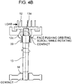
- Fig. 4A illustrates a state with no compression load
- Fig. 4B illustrates a state with a compression load.
- eccentric shaft 13a located at an end of rotary shaft 13 rotates while pushing orbiting bearing 13d of orbiting scroll 12.
- the back pressure acting on the anti-wrap surface of orbiting scroll end plate 12a of orbiting scroll 12 keeps orbiting scroll 12 pressed against fixed scroll 11.
- eccentric shaft 13a receives a force in a direction substantially opposite to the direction in which the refrigerant is compressed, and rotary shaft 13 rotates with a tilt allowed by the clearance between rotary shaft 13 and main bearing 30 and the clearance between rotary shaft 13 and sub-bearing 18.
- Figs. 6A and 6B The load and turning moment acting on orbiting bearing 13d in the gas compression process are as shown in Figs. 6A and 6B.
- Fig. 6A illustrates a case where orbiting bearing 13d has no taper
- Fig. 6B illustrates a case where orbiting bearing 13d has a taper. Illustrated in a lower left area in each of Figs. 6A and 6B is the magnitude of reaction force by gas compression (bearing load) acting on orbiting bearing 13d for each case.
- the tapered shape of orbiting bearing 13d starts from a midway of the sliding surface of eccentric shaft 13a or the tapered shape of eccentric shaft 13a starts from a midway of the sliding surface of orbiting bearing 13d, so that the gap between eccentric shaft 13a and orbiting bearing 13d can be minimized at the start point of the taper. This prevents the surface pressure locally becoming large at the lower end on the open side of orbiting bearing 13d (second end 13db), which promotes formation of an oil film at the sliding portion.
- the tapered shape of orbiting bearing 13d or eccentric shaft 13a may include a straight line, a continuous curve, or a combination thereof. This further distributes surface pressure to moderate a local surface pressure, and a scroll compressor with further lower input and higher efficiency can be provided.
- the scroll compressor includes compression mechanism unit 10 that compresses the refrigerant, motor mechanism unit 20 that drives compression mechanism unit 10, and hermetic container 1 that accommodates compression mechanism unit 10 and motor mechanism unit 20.
- Compression mechanism unit 10 includes fixed scroll 11, orbiting scroll 12, and rotary shaft 13 that drives orbiting scroll 12 to orbit.
- Fixed scroll 11 includes fixed scroll end plate 11a having a disk shape and fixed spiral wrap 11b erecting from fixed scroll end plate 11a
- orbiting scroll 12 includes orbiting scroll end plate 12a having a disk shape and orbiting spiral wrap 12b erecting from the wrap-side end surface of orbiting scroll end plate 12a.
- Compression chamber 15 includes first compression chamber 15A formed on the outer wall side of the orbiting spiral wrap and second compression chamber 15B formed on the inner wall side of orbiting spiral wrap 12b.
- Orbiting scroll 12 is pressed against fixed scroll 11 by back pressure created on the anti-wrap surface side of orbiting scroll end plate 12a.
- the wrap side of orbiting bearing 13d of orbiting scroll 12 is closed by an end plate, and eccentric shaft 13a side of rotary shaft 13 is opened.
- orbiting bearing 13d has a tapered shape of which diameter gradually increases toward the open side of orbiting bearing 13d, or eccentric shaft 13a of rotary shaft 13 inserted in orbiting bearing 13d has a tapered shape of which diameter gradually decreases toward the open side of orbiting bearing 13d.
- the tapered shape of orbiting bearing 13d or eccentric shaft 13a shortens the distance between the point of effort, when the side surface of the wrap of the orbiting scroll receives a tangential gas load, and the point at which the orbiting bearing receives the reaction force, and thereby the turning moment that causes orbiting scroll 12 to turn can be suppressed.
- the behavior of orbiting scroll 12 easily becomes unstable due to, for example, first compression chamber 15A having a larger suction volume than second compression chamber 15B as in the present exemplary embodiment, the behavior of orbiting scroll 12 can be stabilized more effectively.
- the tapered shape of orbiting bearing 13d or eccentric shaft 13a starts from a midway of the sliding surface between orbiting bearing 13d and eccentric shaft 13a. This prevents the surface pressure from locally becoming large at the lower end on the opened side of orbiting bearing 13d (second end 13db), and promotes formation of an oil film between the sliding portions.
- the tapered shape of orbiting bearing 13d or eccentric shaft 13a includes a straight line, a continuous curve, or a combination thereof. This further distributes surface pressure to moderate a local surface pressure, and a scroll compressor with further lower input and higher efficiency can be provided.
- orbiting bearing 13d has a tapered shape of which diameter increases toward the open side of orbiting bearing 13d.
- the angle ⁇ between the tapered shape and the axis of orbiting bearing 13d is set so as to satisfy the following relational expression, where L is the distance between the upper end of orbiting bearing 13d (first end 13da) and the start point of the taper, d is the diameter of the eccentric shaft, and D is the diameter of the orbiting bearing.
- R32 carbon dioxide, or a refrigerant having a double bond between carbons can be used.
- a scroll compressor according to the present disclosure can achieve high efficiency, and is therefore useful for various refrigeration cycle devices such as a hot water heating device, an air conditioner, a water heater, a freezing machine, or the like.
Landscapes
- Engineering & Computer Science (AREA)
- Mechanical Engineering (AREA)
- General Engineering & Computer Science (AREA)
- Rotary Pumps (AREA)
- Applications Or Details Of Rotary Compressors (AREA)
Abstract
Description
- The present disclosure relates to a scroll compressor used for, in particular, an air conditioner, a water heater, or a freezing machine of a refrigerator or the like.
-
PTL 1 discloses a scroll compressor used for an air conditioner or the like. In the scroll compressor, a back pressure region is provided on an anti-wrap surface of an orbiting scroll end plate, and an orbiting scroll is pressed against a fixed scroll, thereby suppressing turning of the orbiting scroll and reducing leakage loss to improve theoretical efficiency and capability of cooling and heating. - PTL 1:
Japanese Patent No. 4892238 - The present disclosure provides a highly efficient and highly reliable scroll compressor in which turning of an orbiting scroll is further reliably suppressed.
- In the scroll compressor of the present disclosure, a back pressure region is formed on an anti-wrap surface of an orbiting scroll end plate, and an orbiting scroll is pressed against a fixed scroll. The wrap side of an orbiting bearing of the orbiting scroll is closed by an end plate, and the crank shaft side is opened. In the scroll compressor, the orbiting bearing of the orbiting scroll has a tapered shape of which diameter gradually increases toward an open side of the orbiting bearing, or an eccentric shaft inserted in the orbiting bearing has a tapered shape of which diameter gradually decreases toward the open side of the orbiting bearing.
-
-
Fig. 1 is a longitudinal sectional view of a scroll compressor according to a first exemplary embodiment. -
Fig. 2 is an enlarged sectional view of an essential part of a compression mechanism unit of the scroll compressor. -
Fig. 3A is a view illustrating a volumetric change of a compression chamber that happens with an orbiting motion of the scroll compressor. -
Fig. 3B is another view illustrating the volumetric change of the compression chamber that happens with the orbiting motion of the scroll compressor. -
Fig. 3C is yet another view illustrating the volumetric change of the compression chamber that happens with the orbiting motion of the scroll compressor. -
Fig. 3D is yet another view illustrating the volumetric change of the compression chamber that happens with the orbiting motion of the scroll compressor. -
Fig. 4A is a view illustrating a rotary shaft where the scroll compressor is performing a compression operation. -
Fig. 4B is a view illustrating a tilt of the rotary shaft where the scroll compressor is performing a compression operation. -
Fig. 5A is a view illustrating an exemplary tapered shape provided to an orbiting bearing of the scroll compressor and a tilt of the rotary shaft. -
Fig. 5B is an explanatory view illustrating a load and a turning moment acting on an eccentric bearing in a gas compression process of the scroll compressor. -
Fig. 6A is an explanatory view illustrating a load and a turning moment acting on the eccentric bearing in a gas compression process in a configuration in which an orbiting bearing or an eccentric shaft of the scroll compressor is tapered; -
Fig. 6B is an explanatory view illustrating a turning moment being suppressed by a tapered shape provided to the orbiting bearing or the eccentric shaft of the scroll compressor. - At the time when the inventors have arrived at the present disclosure, scroll compressors have been configured to press an orbiting scroll against a fixed scroll using back pressure to further stabilize the behavior of the orbiting scroll. The inventors have found that such a configuration has a disadvantage in that the orbiting scroll may separate from the fixed scroll when the turning moment created by the tangential gas load acting on the side surface of the wrap of the orbiting scroll becomes larger than the stabilizing moment created by the back pressure acting on the orbiting scroll. When the orbiting scroll separates from the fixed scroll, the performance of the scroll compressor is deteriorated due to leakage of refrigerant between adjacent compression chambers or between an intermediate pressure region and a compression chamber. The inventors have come to construct the subject matter of the present disclosure in order to solve the problem.
- The present disclosure provides a highly efficient and highly reliable scroll compressor that suppresses turning of an orbiting scroll.
- Hereinafter, an exemplary embodiment will be described in detail with reference to the accompanying drawings. Unnecessary detailed description may be omitted. For example, detailed description of already well-known matters and repeated description of substantially the same configuration may be omitted. This is to avoid an unnecessary redundancy in the following description and to facilitate understanding of a person skilled in the art.
- Note that, the accompanying drawings and the following description are merely presented to help those skilled in the art fully understand the present disclosure, and are not intended to limit the subject matters described in the claims.
- A first exemplary embodiment will be described below with reference to
Figs. 1 to 6B . - As illustrated in
Fig. 1 ,scroll compressor 100 includescompression mechanism unit 10 that compresses a refrigerant and motor mechanism unit 20 that drivescompression mechanism unit 10,compression mechanism unit 10 and motor mechanism unit 20 being disposed inhermetic container 1. -
Hermetic container 1 includesbarrel 1a having a cylindrical shape extending in the up-down direction,lower lid 1b closing a lower opening ofbarrel 1a, andupper lid 1c closing an upper opening ofbarrel 1a.Hermetic container 1 is provided withrefrigerant suction pipe 2 for introducing the refrigerant intocompression mechanism unit 10, andrefrigerant discharge pipe 3 for discharging the refrigerant compressed bycompression mechanism unit 10 to the outside ofhermetic container 1. -
Compression mechanism unit 10 includesfixed scroll 11, orbitingscroll 12, androtary shaft 13 for driving orbitingscroll 12 to orbit. - Motor mechanism unit 20 includes
stator 21 fixed tohermetic container 1, and rotor 22 disposed insidestator 21.Rotary shaft 13 is fixed to rotor 22.Eccentric shaft 13a is provided at an upper end ofrotary shaft 13 to be eccentric torotary shaft 13. Oneccentric shaft 13a, an oil reservoir which is a recess opened to an upper surface ofeccentric shaft 13a is provided. - Main bearing 30 that supports
fixed scroll 11 and orbitingscroll 12 is provided belowfixed scroll 11 and orbitingscroll 12. - Main bearing 30 includes bearing 31 that rotatably supports
rotary shaft 13, andboss housing 32. Main bearing 30 is fixed tohermetic container 1 by welding, shrink fit, or the like. - Fixed
scroll 11 includes fixedscroll end plate 11a having a disk shape, fixedspiral wrap 11b having a spiral shape and erecting from fixedscroll end plate 11a, and outerperipheral wall portion 11c erecting so as to surround the circumference of fixedspiral wrap 11b.Discharge port 14 is provided substantially at a center portion of fixedscroll end plate 11a. -
Orbiting scroll 12 includes orbitingscroll end plate 12a having a disk shape, orbitingspiral wrap 12b erecting from one surface (wrap-side end surface) of orbitingscroll end plate 12a, andcylindrical boss portion 12c formed on the other surface (anti-wrap-side end surface) of orbitingscroll end plate 12a. The other surface of orbitingscroll end plate 12a is a surface opposite to the wrap-side end surface of orbitingscroll end plate 12a. - As illustrated in
Fig. 2 , orbitingbearing 13d is fit incylindrical boss portion 12c. The wrap side of orbitingbearing 13d is closed by orbitingscroll end plate 12a, and the anti-wrap side is opened.Eccentric shaft 13a ofrotary shaft 13 is inserted from the open side of orbitingbearing 13d. In the following description, the end on the wrap side of orbitingbearing 13d may be referred to as first end 13da, and the end on the open side may be referred to as second end 13db. -
Fixed spiral wrap 11b of fixedscroll 11 and orbitingspiral wrap 12b of orbitingscroll 12 mesh with each other, and a plurality ofcompression chambers 15 is formed between fixedspiral wrap 11b and orbitingspiral wrap 12b. -
Boss portion 12c is formed substantially at the center of orbitingscroll end plate 12a.Boss portion 12c is accommodated inboss housing 32 witheccentric shaft 13a inserted inboss portion 12c. - Fixed
scroll 11 is fixed tomain bearing 30 by outerperipheral wall 11c using a plurality of bolts (not shown). Meanwhile, the movement of orbitingscroll 12 with respect to fixedscroll 11 is restricted by spin-restrainingmember 17 such as an Oldham ring. Spin-restrainingmember 17 that restrains spinning of orbitingscroll 12 is provided betweenfixed scroll 11 andmain bearing 30. This makes orbitingscroll 12 to orbit without spinning with respect to fixedscroll 11 aseccentric shaft 13a ofrotary shaft 13 orbits. -
Oil storage part 4 that stores lubricating oil is formed at the bottom ofhermetic container 1.Lower end 13b ofrotary shaft 13 is rotatably supported by sub-bearing 18 disposed at the lower portion ofhermetic container 1. -
Oil pump 5 of a displacement type is provided at the lower end ofrotary shaft 13.Oil pump 5 is disposed so as a suction port ofoil pump 5 to be inoil storage part 4.Oil pump 5 is driven byrotary shaft 13 and reliably sucks up lubricating oil inoil storage part 4 provided at the bottom ofhermetic container 1 at any pressure condition and operating speed, which eliminates concern about loss of oil. - Rotary shaft
oil supply hole 13c extending fromlower end 13b ofrotary shaft 13 toeccentric shaft 13a is formed inrotary shaft 13. The lubricating oil sucked up byoil pump 5 is supplied to a bearing ofsub-bearing 18 andbearing 31, and intoboss portion 12c through rotary shaftoil supply hole 13c inrotary shaft 13. - The refrigerant suctioned from
refrigerant suction pipe 2 is introduced fromsuction port 15a tocompression chamber 15.Compression chamber 15 moves from the outer peripheral side toward the central portion while reducing its volume. The refrigerant that has reached a predetermined pressure incompression chamber 15 is discharged to dischargechamber 6 fromdischarge port 14 provided at the central portion of fixedscroll 11.Discharge port 14 is provided with a discharge reed valve (not shown). The refrigerant that has reached a predetermined pressure incompression chamber 15 pushes open the discharge reed valve and is discharged to dischargechamber 6. The refrigerant discharged to dischargechamber 6 is led out to the upper portion ofhermetic container 1, and is then discharged throughrefrigerant discharge pipe 3. - In
scroll compressor 100 according to the present exemplary embodiment, as shown in the enlarged sectional view of the essential part inFig. 2 ,boss housing 32 serves as high-pressure region A, and the outer peripheral portion of orbitingscroll 12 in which spin-restrainingmember 17 is disposed serves as intermediate-pressure regionB. Orbiting scroll 12 is pressed against fixedscroll 11. The configuration will be described below. -
Eccentric shaft 13a is inserted inboss portion 12c via orbitingbearing 13d so as to be driven to orbit.Oil groove 13e is formed in an outer peripheral surface ofeccentric shaft 13a. - Sealing
member 33 having a ring shape is provided on a thrust surface ofmain bearing 30 that receives a thrust force from orbitingscroll end plate 12a. Sealingmember 33 is disposed on the outer periphery ofboss housing 32. - The inside of
hermetic container 1 is filled with refrigerant of the same high pressure as the refrigerant discharged to dischargechamber 6. Rotary shaftoil supply hole 13c is opened at the upper end ofeccentric shaft 13a. Thus, the inside ofboss portion 12c serves as a high-pressure region A of which pressure is equivalent to the pressure of the discharged refrigerant. - The lubricating oil introduced into
boss portion 12c through rotary shaftoil supply hole 13c is supplied to orbitingbearing 13d andboss housing 32 throughoil groove 13e formed in the outer peripheral surface ofeccentric shaft 13a. Since sealingmember 33 is provided at the outer periphery ofboss housing 32, the inside ofboss housing 32 serves as high-pressure region A. - Orbiting
scroll end plate 12a is provided with firstoil introduction hole 51 directed to the inside ofboss portion 12c, first oil lead-out hole 52 which is a through hole in the outer peripheral portion of the wrap-side end surface, and first end plateoil communication passage 53 that provides communication between firstoil introduction hole 51 and first oil lead-out hole 52. - Orbiting
scroll end plate 12a is provided with secondoil introduction hole 61 that opens to intermediate-pressure region B at the outer peripheral portion of orbitingscroll 12, second oil lead-out hole 62 that opens tocompression chamber 15, and second end plateoil communication passage 63 that provides communication between secondoil introduction hole 61 and second oil lead-out hole 62. In the example of the present exemplary embodiment, secondoil introduction hole 61 opens at the upper surface of orbitingscroll end plate 12a. - In this configuration, second oil lead-
out hole 62 of orbitingscroll 12 intermittently provides communication between intermediate-pressure region B andcompression chamber 15. This introduces the intermediate pressure incompression chamber 15 to intermediate-pressure region B, and orbitingscroll 12 can be pressed against fixedscroll 11 with a minimum necessary load under various operating conditions. Accordingly, separation of orbitingscroll 12 from fixedscroll 11 can be prevented while reducing friction loss of the compressor, and thereby the airtightness ofcompression chamber 15 can be improved. -
Figs. 3A to 3D are views illustrating the volumetric change of the compression chamber caused by the orbiting motion in the scroll compressor according to the present exemplary embodiment, where the views each illustrates a meshing state of orbitingscroll 12 and fixedscroll 11 looking from the back surface of orbitingscroll 12.Fig. 3B illustrates a state in which the rotation is advanced by 90 degrees fromFig. 3A ,Fig. 3C illustrates a state in which the rotation is further advanced by 90 degrees fromFig. 3B , andFig. 3D illustrates a state in which the rotation is further advanced by 90 degrees fromFig. 3C . - Fixed
scroll 11 and orbitingscroll 12 form a plurality ofcompression chambers 15. As illustrated inFig. 3A ,first compression chamber 15A is formed on an outer wall side of orbitingspiral wrap 12b, and as illustrated inFig. 3C ,second compression chamber 15B is formed on an inner wall side of orbitingspiral wrap 12b. - Outer peripheral end portion 11be of fixed
spiral wrap 11b is extended so as outer peripheral end 11be of fixedspiral wrap 11b and outer peripheral end 12be of orbitingspiral wrap 12b to be at the same position when fixedscroll 11 and orbitingscroll 12 mesh with each other. Accordingly,first compression chamber 15A confines the refrigerant in a place that is shifted by approximately 180 degrees from the place wheresecond compression chamber 15B confines the refrigerant. The suction volume offirst compression chamber 15A is larger than the suction volume ofsecond compression chamber 15B. - In
scroll compressor 100 according to the present exemplary embodiment, bore surface 13dc of orbitingbearing 13d has a tapered shape (first tapered shape T1) of which diameter increases toward the open end (second end 13db) as illustrated inFig. 5A . Alternatively, inscroll compressor 100,eccentric shaft 13a may have a tapered shape (second tapered shape T2) of which diameter decreases toward the open side of orbitingbearing 13d as illustrated inFig. 5B . In a sectional view of orbiting bearing 13d in a plane including the axis of orbitingbearing 13d, an angle θ between first tapered shape T1 or second tapered shape T2 and the axis of orbitingbearing 13d may be set to an angle equal to or larger than the maximum angle at whichrotary shaft 13 can tilt and to satisfy the following relational expression where L is the distance between the upper end of orbitingbearing 13d (first end 13da) and the start point of taper, d is the diameter of the eccentric shaft, and D is the diameter of the inner wall of an eccentric bearing.
- In the present exemplary embodiment, the maximum angle at which
rotary shaft 13 can tilt is defined by the clearance betweenmain bearing 30 androtary shaft 13 and the clearance betweensub-bearing 18 androtary shaft 13 illustrated inFigs. 4A and4B . - As illustrated in
Figs. 5A and 5B , the tapered shape of orbitingbearing 13d or the tapered shape ofeccentric shaft 13a may start from a position at a midway within a range along the axial direction ofeccentric bearing 13d, in which range inner wall 13dc ofeccentric bearing 13d and outer periphery 13ab ofeccentric shaft 13a slide against each other. The tapered shape of orbitingbearing 13d oreccentric shaft 13a may include a straight line, a continuous curve, or a combination thereof. - Operations and advantageous effects of
scroll compressor 100 configured as described above will be described below. -
Figs. 4A and4B illustrate the rotating state ofrotary shaft 13 that makes the orbiting scroll orbit.Fig. 4A illustrates a state with no compression load, andFig. 4B illustrates a state with a compression load. When gas is compressed inscroll compressor 100,eccentric shaft 13a located at an end ofrotary shaft 13 rotates while pushing orbiting bearing 13d of orbitingscroll 12. During this motion, the back pressure acting on the anti-wrap surface of orbitingscroll end plate 12a of orbitingscroll 12 keeps orbitingscroll 12 pressed against fixedscroll 11. Thus, as illustrated inFig. 4B ,eccentric shaft 13a receives a force in a direction substantially opposite to the direction in which the refrigerant is compressed, androtary shaft 13 rotates with a tilt allowed by the clearance betweenrotary shaft 13 andmain bearing 30 and the clearance betweenrotary shaft 13 andsub-bearing 18. - The load and turning moment acting on orbiting
bearing 13d in the gas compression process are as shown inFigs. 6A and 6B. Fig. 6A illustrates a case where orbitingbearing 13d has no taper, andFig. 6B illustrates a case where orbitingbearing 13d has a taper. Illustrated in a lower left area in each ofFigs. 6A and 6B is the magnitude of reaction force by gas compression (bearing load) acting on orbitingbearing 13d for each case. - For the case in
Fig. 6B where orbitingbearing 13d has a tapered shape, concentration of the reaction force by gas compression at the lower end of orbitingbearing 13d (second end 13db) can be avoided even whenrotary shaft 13 rotates with a tilt with respect to the axis. Accordingly, turning moment Z that causes orbitingscroll 12 to turn can be suppressed. That is, shortening the distance between the point of effort at which the side surface of the wrap of the orbiting scroll receives the tangential gas load acting on orbitingscroll 12 and the point at which orbitingbearing 13d receives the reaction force suppresses the turning moment that causes orbitingscroll 12 to turn. This stabilizes the behavior of orbitingscroll 12 and thereby improves reliability of the compressor, making the scroll compressor highly efficient. - For the case in
Fig. 6A , concentration of the reaction force by gas compression at the lower end of orbitingbearing 13d (second end 13db) makes the clearance betweeneccentric shaft 13a and orbitingbearing 13d become larger toward the upper end of orbitingbearing 13d (first end 13da). This makes it difficult to form a uniform oil film in the gap betweeneccentric shaft 13a and orbitingbearing 13d. Meanwhile, for the case inFig. 6B , an appropriate clearance is formed betweeneccentric shaft 13a and orbitingbearing 13d, which prevents metal contact and promotes formation of an oil film at the sliding portion. That is, the gap betweeneccentric shaft 13a that is tilted and orbitingbearing 13d can be appropriately set, and an oil film can be formed in the gap to prevent local metal contact. Accordingly, the compressor is made further highly efficient. - Furthermore, in the present exemplary embodiment, the tapered shape of orbiting
bearing 13d starts from a midway of the sliding surface ofeccentric shaft 13a or the tapered shape ofeccentric shaft 13a starts from a midway of the sliding surface of orbitingbearing 13d, so that the gap betweeneccentric shaft 13a and orbitingbearing 13d can be minimized at the start point of the taper. This prevents the surface pressure locally becoming large at the lower end on the open side of orbitingbearing 13d (second end 13db), which promotes formation of an oil film at the sliding portion. - The tapered shape of orbiting
bearing 13d oreccentric shaft 13a may include a straight line, a continuous curve, or a combination thereof. This further distributes surface pressure to moderate a local surface pressure, and a scroll compressor with further lower input and higher efficiency can be provided. - As described above, the scroll compressor according to the present exemplary embodiment includes
compression mechanism unit 10 that compresses the refrigerant, motor mechanism unit 20 that drivescompression mechanism unit 10, andhermetic container 1 that accommodatescompression mechanism unit 10 and motor mechanism unit 20.Compression mechanism unit 10 includes fixedscroll 11, orbitingscroll 12, androtary shaft 13 that drives orbitingscroll 12 to orbit. Fixedscroll 11 includes fixedscroll end plate 11a having a disk shape and fixedspiral wrap 11b erecting from fixedscroll end plate 11a, and orbitingscroll 12 includes orbitingscroll end plate 12a having a disk shape and orbitingspiral wrap 12b erecting from the wrap-side end surface of orbitingscroll end plate 12a.Fixed spiral wrap 11b and orbitingspiral wrap 12b mesh with each other, and a plurality ofcompression chambers 15 is formed between fixedspiral wrap 11b and orbitingspiral wrap 12b.Compression chamber 15 includesfirst compression chamber 15A formed on the outer wall side of the orbiting spiral wrap andsecond compression chamber 15B formed on the inner wall side of orbitingspiral wrap 12b. Orbitingscroll 12 is pressed against fixedscroll 11 by back pressure created on the anti-wrap surface side of orbitingscroll end plate 12a. The wrap side of orbiting bearing 13d of orbitingscroll 12 is closed by an end plate, andeccentric shaft 13a side ofrotary shaft 13 is opened. Inscroll compressor 100, orbitingbearing 13d has a tapered shape of which diameter gradually increases toward the open side of orbitingbearing 13d, oreccentric shaft 13a ofrotary shaft 13 inserted in orbitingbearing 13d has a tapered shape of which diameter gradually decreases toward the open side of orbitingbearing 13d. - In the exemplary embodiment, the tapered shape of orbiting
bearing 13d oreccentric shaft 13a shortens the distance between the point of effort, when the side surface of the wrap of the orbiting scroll receives a tangential gas load, and the point at which the orbiting bearing receives the reaction force, and thereby the turning moment that causes orbitingscroll 12 to turn can be suppressed. This stabilizes the behavior of orbitingscroll 12 and thereby makes the scroll compressor highly efficient. In a case where the behavior of orbitingscroll 12 easily becomes unstable due to, for example,first compression chamber 15A having a larger suction volume thansecond compression chamber 15B as in the present exemplary embodiment, the behavior of orbitingscroll 12 can be stabilized more effectively. - In the example of the present exemplary embodiment, the tapered shape of orbiting
bearing 13d oreccentric shaft 13a starts from a midway of the sliding surface between orbiting bearing 13d andeccentric shaft 13a. This prevents the surface pressure from locally becoming large at the lower end on the opened side of orbitingbearing 13d (second end 13db), and promotes formation of an oil film between the sliding portions. - In the example of the present exemplary embodiment, the tapered shape of orbiting
bearing 13d oreccentric shaft 13a includes a straight line, a continuous curve, or a combination thereof. This further distributes surface pressure to moderate a local surface pressure, and a scroll compressor with further lower input and higher efficiency can be provided. - In
scroll compressor 100 according to the present exemplary embodiment, orbitingbearing 13d has a tapered shape of which diameter increases toward the open side of orbitingbearing 13d. In a cross section of orbitingbearing 13d in a plane including the axis ofeccentric bearing 13d, the angle θ between the tapered shape and the axis of orbitingbearing 13d is set so as to satisfy the following relational expression, where L is the distance between the upper end of orbitingbearing 13d (first end 13da) and the start point of the taper, d is the diameter of the eccentric shaft, and D is the diameter of the orbiting bearing.
- As a result, an appropriate clearance can be formed between the eccentric shaft and the orbiting bearing, and thereby metal contact can be prevented and formation of an oil film at the sliding portion can be promoted.
- The present disclosure has been described using the exemplary embodiment described above. Since the exemplary embodiment is for illustrating the technology in the present disclosure, various modifications, replacements, additions, omissions, or the like, can be made within the scope of the claims or equivalents thereof.
- As the refrigerant of the scroll compressor of the present disclosure, R32, carbon dioxide, or a refrigerant having a double bond between carbons can be used.
- A scroll compressor according to the present disclosure can achieve high efficiency, and is therefore useful for various refrigeration cycle devices such as a hot water heating device, an air conditioner, a water heater, a freezing machine, or the like.
-
- 1
- hermetic container
- 1a
- barrel
- 1b
- lower lid
- 1c
- upper lid
- 2
- refrigerant suction pipe
- 3
- refrigerant discharge pipe
- 4
- oil storage part
- 5
- oil pump
- 6
- discharge chamber
- 10
- compression mechanism unit
- 11
- fixed scroll
- 11a
- fixed scroll end plate
- 11b
- fixed spiral wrap
- 11be
- outer peripheral end portion
- 12
- orbiting scroll
- 12a
- orbiting scroll end plate
- 12b
- orbiting spiral wrap
- 12be
- outer peripheral end portion
- 12c
- boss portion
- 13
- rotary shaft
- 13a
- eccentric shaft
- 13ab
- outer periphery
- 13b
- lower end
- 13c
- rotary shaft oil supply hole
- 13d
- orbiting bearing
- 13da
- first end
- 13db
- second end
- 13dc
- inner wall (bore surface)
- 13e
- oil groove
- 14
- discharge port
- 15
- compression chamber
- 15A
- first compression chamber
- 15B
- second compression chamber
- 15a
- suction port
- 17
- spin-restraining member
- 18
- sub-bearing
- 20
- motor mechanism unit
- 21
- stator
- 22
- rotor
- 30
- main bearing
- 31
- bearing
- 32
- boss housing
- 33
- sealing member
- 51
- first oil introduction hole
- 52
- first oil lead-out hole
- 53
- first end plate oil communication passage
- 61
- second oil introduction hole
- 62
- second oil lead-out hole
- 63
- second end plate oil communication passage
- 100
- scroll compressor
Claims (6)
- A scroll compressor comprising:a compression mechanism unit that compresses a refrigerant and includes a fixed scroll, an orbiting scroll, and a rotary shaft that has an eccentric shaft to drive the orbiting scroll to orbit;a motor mechanism unit that drives the compression mechanism unit; anda hermetic container accommodating the compression mechanism unit and the motor mechanism unit,wherein the fixed scroll includes a fixed scroll end plate having a disk shape and a fixed spiral wrap erecting from the fixed scroll end plate,the orbiting scroll includes an orbiting scroll end plate having a disk shape, an orbiting spiral wrap erecting from one surface of the orbiting scroll end plate, a boss portion having a cylindrical shape and disposed on another surface of the orbiting scroll end plate, and an orbiting bearing that is fit in the boss portion and receives the eccentric shaft,the fixed spiral wrap and the orbiting spiral wrap mesh with each other to form a plurality of compression chambers between the fixed spiral wrap and the orbiting spiral wrap,the orbiting scroll is pressed against the fixed scroll by a back pressure from a side of the other surface of the orbiting scroll end plate,the orbiting bearing has a first end on a side of the orbiting scroll end plate and a second end on an opposite side of the first end, the eccentric shaft being inserted in the orbiting bearing from the second end, andthe scroll compressor is configured thatan inner wall of the orbiting bearing has a first tapered shape of which diameter increases from a first end side toward a second end side oran outer periphery of the eccentric shaft inserted in the orbiting bearing has a second tapered shape of which diameter decreases from the first end side toward the second end side.
- The scroll compressor according to Claim 1, wherein the first tapered shape or the second tapered shape starts from a position at a midway within a range along an axial direction of the eccentric bearing in which range the inner wall of the eccentric bearing and the outer periphery of the eccentric shaft slide against each other.
- The scroll compressor according to Claim 1 or 2, wherein the first tapered shape or the second tapered shape includes a straight line, a continuous curve, or a combination of the straight line and the continuous curve.
- The scroll compressor according to any one of Claims 1 to 3, wherein in a sectional view in a plane including an axis of the orbiting bearing, the first tapered shape or the second tapered shape is configured thatan angle θ between a surface of the first tapered shape or the second tapered shape and the axis is larger than an angle at which the rotary shaft is allowed to tilt, andsatisfies a relational expression expressed below where L is a distance between the first end of the orbiting bearing and a start point of the first tapered shape or the second tapered shape, d is a diameter of the eccentric shaft, and D is a diameter of the inner wall of the orbiting bearing,

- The scroll compressor according to Claim 4, whereinthe scroll compressor includes a main bearing and a sub-bearing that rotatably support the rotary shaft, andthe angle at which the rotary shaft is allowed to tilt is defined by a clearance between the main bearing and the rotary shaft and a clearance between the sub-bearing and the rotary shaft.
- The scroll compressor according to any one of Claims 1 to 5, whereinthe plurality of compression chambers includes a first compression chamber disposed on an outer wall side of the orbiting spiral wrap and a second compression chamber disposed on an inner wall side of the orbiting spiral wrap, anda suction volume of the first compression chamber is larger than a suction volume of the second compression chamber.
Applications Claiming Priority (2)
| Application Number | Priority Date | Filing Date | Title |
|---|---|---|---|
| JP2020017533 | 2020-02-05 | ||
| PCT/JP2021/001571 WO2021157332A1 (en) | 2020-02-05 | 2021-01-19 | Scroll compressor |
Publications (3)
| Publication Number | Publication Date |
|---|---|
| EP4102074A1 true EP4102074A1 (en) | 2022-12-14 |
| EP4102074A4 EP4102074A4 (en) | 2023-07-12 |
| EP4102074B1 EP4102074B1 (en) | 2025-07-23 |
Family
ID=77199272
Family Applications (1)
| Application Number | Title | Priority Date | Filing Date |
|---|---|---|---|
| EP21751392.8A Active EP4102074B1 (en) | 2020-02-05 | 2021-01-19 | Scroll compressor |
Country Status (4)
| Country | Link |
|---|---|
| EP (1) | EP4102074B1 (en) |
| JP (1) | JP7689309B2 (en) |
| CN (1) | CN115053069B (en) |
| WO (1) | WO2021157332A1 (en) |
Families Citing this family (1)
| Publication number | Priority date | Publication date | Assignee | Title |
|---|---|---|---|---|
| KR102863008B1 (en) * | 2023-08-31 | 2025-09-23 | 엘지전자 주식회사 | Scroll Compressor |
Family Cites Families (15)
| Publication number | Priority date | Publication date | Assignee | Title |
|---|---|---|---|---|
| GB768854A (en) * | 1953-10-29 | 1957-02-20 | Chrysler Corp | Improvements in or relating to a gas turbine power plant |
| US4836758A (en) * | 1987-11-20 | 1989-06-06 | Copeland Corporation | Scroll compressor with canted drive busing surface |
| JPH0472484A (en) * | 1990-07-10 | 1992-03-06 | Mitsubishi Electric Corp | Scroll compressor |
| JP2930046B2 (en) * | 1997-03-07 | 1999-08-03 | 三菱電機株式会社 | Scroll compressor |
| JP3214417B2 (en) * | 1997-11-11 | 2001-10-02 | ダイキン工業株式会社 | Scroll type fluid machine |
| JP2000179481A (en) * | 1998-12-14 | 2000-06-27 | Hitachi Ltd | Scroll compressor |
| KR100414123B1 (en) * | 2001-12-26 | 2004-01-07 | 엘지전자 주식회사 | Device for reducing frictional loss of scroll compressor |
| KR100451232B1 (en) * | 2002-02-19 | 2004-10-02 | 엘지전자 주식회사 | Structure for supporting orbit scroll in scroll compressor |
| JP4892238B2 (en) | 2003-10-17 | 2012-03-07 | パナソニック株式会社 | Scroll compressor |
| JP6578504B2 (en) * | 2013-04-30 | 2019-09-25 | パナソニックIpマネジメント株式会社 | Scroll compressor |
| JP6484796B2 (en) * | 2014-04-24 | 2019-03-20 | パナソニックIpマネジメント株式会社 | Scroll compressor |
| JP2017082840A (en) * | 2015-10-26 | 2017-05-18 | ダイキン工業株式会社 | Bearing structure and scroll type compressor |
| WO2018096823A1 (en) * | 2016-11-24 | 2018-05-31 | パナソニックIpマネジメント株式会社 | Asymmetrical scroll compressor |
| JP6688972B2 (en) * | 2017-01-27 | 2020-04-28 | パナソニックIpマネジメント株式会社 | Scroll compressor |
| JP6767640B2 (en) * | 2019-02-06 | 2020-10-14 | パナソニックIpマネジメント株式会社 | Scroll compressor |
-
2021
- 2021-01-19 WO PCT/JP2021/001571 patent/WO2021157332A1/en not_active Ceased
- 2021-01-19 CN CN202180010824.5A patent/CN115053069B/en active Active
- 2021-01-19 EP EP21751392.8A patent/EP4102074B1/en active Active
- 2021-01-19 JP JP2021575692A patent/JP7689309B2/en active Active
Also Published As
| Publication number | Publication date |
|---|---|
| EP4102074B1 (en) | 2025-07-23 |
| EP4102074A4 (en) | 2023-07-12 |
| WO2021157332A1 (en) | 2021-08-12 |
| CN115053069A (en) | 2022-09-13 |
| CN115053069B (en) | 2024-08-13 |
| JP7689309B2 (en) | 2025-06-06 |
| JPWO2021157332A1 (en) | 2021-08-12 |
Similar Documents
| Publication | Publication Date | Title |
|---|---|---|
| EP2863059B1 (en) | Scroll compression device | |
| EP2636902B1 (en) | Scroll compressor | |
| JP5260608B2 (en) | Scroll compressor | |
| CN110234880B (en) | scroll compressor | |
| CN110234881B (en) | scroll compressor | |
| US11434908B2 (en) | Compressor having lubrication structure for thrust surface | |
| CN105765226A (en) | Scroll compressor | |
| EP4102074B1 (en) | Scroll compressor | |
| US11022121B2 (en) | Scroll compressor | |
| US11015600B2 (en) | Scroll compressor having sub-discharge port with involute-shaped opening | |
| KR101099094B1 (en) | Scroll compressor | |
| JP4836712B2 (en) | Hermetic scroll compressor | |
| CN119585527A (en) | Scroll compressor and refrigeration device | |
| EP4098877B1 (en) | Scroll compressor | |
| JP7702647B2 (en) | Scroll Compressor | |
| CN113454341B (en) | Scroll compressor having a discharge port | |
| JP2016156297A (en) | Scroll compressor | |
| JP2008121481A (en) | Scroll fluid machinery | |
| US8939741B2 (en) | Scroll compressor | |
| WO2022264792A1 (en) | Scroll compressor | |
| JP2011137523A (en) | Rotary shaft and compressor | |
| JPH08312560A (en) | Electric compressor |
Legal Events
| Date | Code | Title | Description |
|---|---|---|---|
| STAA | Information on the status of an ep patent application or granted ep patent |
Free format text: STATUS: THE INTERNATIONAL PUBLICATION HAS BEEN MADE |
|
| PUAI | Public reference made under article 153(3) epc to a published international application that has entered the european phase |
Free format text: ORIGINAL CODE: 0009012 |
|
| STAA | Information on the status of an ep patent application or granted ep patent |
Free format text: STATUS: REQUEST FOR EXAMINATION WAS MADE |
|
| 17P | Request for examination filed |
Effective date: 20220905 |
|
| AK | Designated contracting states |
Kind code of ref document: A1 Designated state(s): AL AT BE BG CH CY CZ DE DK EE ES FI FR GB GR HR HU IE IS IT LI LT LU LV MC MK MT NL NO PL PT RO RS SE SI SK SM TR |
|
| DAV | Request for validation of the european patent (deleted) | ||
| DAX | Request for extension of the european patent (deleted) | ||
| A4 | Supplementary search report drawn up and despatched |
Effective date: 20230613 |
|
| RIC1 | Information provided on ipc code assigned before grant |
Ipc: F04C 29/00 20060101ALI20230606BHEP Ipc: F04C 18/02 20060101AFI20230606BHEP |
|
| GRAP | Despatch of communication of intention to grant a patent |
Free format text: ORIGINAL CODE: EPIDOSNIGR1 |
|
| STAA | Information on the status of an ep patent application or granted ep patent |
Free format text: STATUS: GRANT OF PATENT IS INTENDED |
|
| INTG | Intention to grant announced |
Effective date: 20250217 |
|
| GRAS | Grant fee paid |
Free format text: ORIGINAL CODE: EPIDOSNIGR3 |
|
| GRAA | (expected) grant |
Free format text: ORIGINAL CODE: 0009210 |
|
| STAA | Information on the status of an ep patent application or granted ep patent |
Free format text: STATUS: THE PATENT HAS BEEN GRANTED |
|
| AK | Designated contracting states |
Kind code of ref document: B1 Designated state(s): AL AT BE BG CH CY CZ DE DK EE ES FI FR GB GR HR HU IE IS IT LI LT LU LV MC MK MT NL NO PL PT RO RS SE SI SK SM TR |
|
| REG | Reference to a national code |
Ref country code: GB Ref legal event code: FG4D |
|
| REG | Reference to a national code |
Ref country code: CH Ref legal event code: EP |
|
| REG | Reference to a national code |
Ref country code: IE Ref legal event code: FG4D |
|
| REG | Reference to a national code |
Ref country code: DE Ref legal event code: R096 Ref document number: 602021034664 Country of ref document: DE |
|
| REG | Reference to a national code |
Ref country code: NL Ref legal event code: MP Effective date: 20250723 |
|
| PG25 | Lapsed in a contracting state [announced via postgrant information from national office to epo] |
Ref country code: PT Free format text: LAPSE BECAUSE OF FAILURE TO SUBMIT A TRANSLATION OF THE DESCRIPTION OR TO PAY THE FEE WITHIN THE PRESCRIBED TIME-LIMIT Effective date: 20251124 |
|
| PG25 | Lapsed in a contracting state [announced via postgrant information from national office to epo] |
Ref country code: NL Free format text: LAPSE BECAUSE OF FAILURE TO SUBMIT A TRANSLATION OF THE DESCRIPTION OR TO PAY THE FEE WITHIN THE PRESCRIBED TIME-LIMIT Effective date: 20250723 |
|
| REG | Reference to a national code |
Ref country code: AT Ref legal event code: MK05 Ref document number: 1816655 Country of ref document: AT Kind code of ref document: T Effective date: 20250723 |
|
| PG25 | Lapsed in a contracting state [announced via postgrant information from national office to epo] |
Ref country code: IS Free format text: LAPSE BECAUSE OF FAILURE TO SUBMIT A TRANSLATION OF THE DESCRIPTION OR TO PAY THE FEE WITHIN THE PRESCRIBED TIME-LIMIT Effective date: 20251123 |
|
| PG25 | Lapsed in a contracting state [announced via postgrant information from national office to epo] |
Ref country code: NO Free format text: LAPSE BECAUSE OF FAILURE TO SUBMIT A TRANSLATION OF THE DESCRIPTION OR TO PAY THE FEE WITHIN THE PRESCRIBED TIME-LIMIT Effective date: 20251023 |
|
| REG | Reference to a national code |
Ref country code: LT Ref legal event code: MG9D |
|
| PG25 | Lapsed in a contracting state [announced via postgrant information from national office to epo] |
Ref country code: AT Free format text: LAPSE BECAUSE OF FAILURE TO SUBMIT A TRANSLATION OF THE DESCRIPTION OR TO PAY THE FEE WITHIN THE PRESCRIBED TIME-LIMIT Effective date: 20250723 |
|
| PG25 | Lapsed in a contracting state [announced via postgrant information from national office to epo] |
Ref country code: FI Free format text: LAPSE BECAUSE OF FAILURE TO SUBMIT A TRANSLATION OF THE DESCRIPTION OR TO PAY THE FEE WITHIN THE PRESCRIBED TIME-LIMIT Effective date: 20250723 |
|
| PG25 | Lapsed in a contracting state [announced via postgrant information from national office to epo] |
Ref country code: HR Free format text: LAPSE BECAUSE OF FAILURE TO SUBMIT A TRANSLATION OF THE DESCRIPTION OR TO PAY THE FEE WITHIN THE PRESCRIBED TIME-LIMIT Effective date: 20250723 |
|
| PG25 | Lapsed in a contracting state [announced via postgrant information from national office to epo] |
Ref country code: GR Free format text: LAPSE BECAUSE OF FAILURE TO SUBMIT A TRANSLATION OF THE DESCRIPTION OR TO PAY THE FEE WITHIN THE PRESCRIBED TIME-LIMIT Effective date: 20251024 |
|
| PG25 | Lapsed in a contracting state [announced via postgrant information from national office to epo] |
Ref country code: SE Free format text: LAPSE BECAUSE OF FAILURE TO SUBMIT A TRANSLATION OF THE DESCRIPTION OR TO PAY THE FEE WITHIN THE PRESCRIBED TIME-LIMIT Effective date: 20250723 |
|
| PG25 | Lapsed in a contracting state [announced via postgrant information from national office to epo] |
Ref country code: LV Free format text: LAPSE BECAUSE OF FAILURE TO SUBMIT A TRANSLATION OF THE DESCRIPTION OR TO PAY THE FEE WITHIN THE PRESCRIBED TIME-LIMIT Effective date: 20250723 |
|
| PG25 | Lapsed in a contracting state [announced via postgrant information from national office to epo] |
Ref country code: BG Free format text: LAPSE BECAUSE OF FAILURE TO SUBMIT A TRANSLATION OF THE DESCRIPTION OR TO PAY THE FEE WITHIN THE PRESCRIBED TIME-LIMIT Effective date: 20250723 Ref country code: PL Free format text: LAPSE BECAUSE OF FAILURE TO SUBMIT A TRANSLATION OF THE DESCRIPTION OR TO PAY THE FEE WITHIN THE PRESCRIBED TIME-LIMIT Effective date: 20250723 |
|
| PG25 | Lapsed in a contracting state [announced via postgrant information from national office to epo] |
Ref country code: RS Free format text: LAPSE BECAUSE OF FAILURE TO SUBMIT A TRANSLATION OF THE DESCRIPTION OR TO PAY THE FEE WITHIN THE PRESCRIBED TIME-LIMIT Effective date: 20251023 |
|
| PG25 | Lapsed in a contracting state [announced via postgrant information from national office to epo] |
Ref country code: ES Free format text: LAPSE BECAUSE OF FAILURE TO SUBMIT A TRANSLATION OF THE DESCRIPTION OR TO PAY THE FEE WITHIN THE PRESCRIBED TIME-LIMIT Effective date: 20250723 |
|
| PG25 | Lapsed in a contracting state [announced via postgrant information from national office to epo] |
Ref country code: SM Free format text: LAPSE BECAUSE OF FAILURE TO SUBMIT A TRANSLATION OF THE DESCRIPTION OR TO PAY THE FEE WITHIN THE PRESCRIBED TIME-LIMIT Effective date: 20250723 |
|
| PG25 | Lapsed in a contracting state [announced via postgrant information from national office to epo] |
Ref country code: DK Free format text: LAPSE BECAUSE OF FAILURE TO SUBMIT A TRANSLATION OF THE DESCRIPTION OR TO PAY THE FEE WITHIN THE PRESCRIBED TIME-LIMIT Effective date: 20250723 |
|
| PGFP | Annual fee paid to national office [announced via postgrant information from national office to epo] |
Ref country code: DE Payment date: 20260121 Year of fee payment: 6 |
|
| PG25 | Lapsed in a contracting state [announced via postgrant information from national office to epo] |
Ref country code: IT Free format text: LAPSE BECAUSE OF FAILURE TO SUBMIT A TRANSLATION OF THE DESCRIPTION OR TO PAY THE FEE WITHIN THE PRESCRIBED TIME-LIMIT Effective date: 20250723 |
|
| PG25 | Lapsed in a contracting state [announced via postgrant information from national office to epo] |
Ref country code: CZ Free format text: LAPSE BECAUSE OF FAILURE TO SUBMIT A TRANSLATION OF THE DESCRIPTION OR TO PAY THE FEE WITHIN THE PRESCRIBED TIME-LIMIT Effective date: 20250723 |
|
| PG25 | Lapsed in a contracting state [announced via postgrant information from national office to epo] |
Ref country code: SK Free format text: LAPSE BECAUSE OF FAILURE TO SUBMIT A TRANSLATION OF THE DESCRIPTION OR TO PAY THE FEE WITHIN THE PRESCRIBED TIME-LIMIT Effective date: 20250723 Ref country code: EE Free format text: LAPSE BECAUSE OF FAILURE TO SUBMIT A TRANSLATION OF THE DESCRIPTION OR TO PAY THE FEE WITHIN THE PRESCRIBED TIME-LIMIT Effective date: 20250723 |