EP4102009A1 - Flagpole - Google Patents
Flagpole Download PDFInfo
- Publication number
- EP4102009A1 EP4102009A1 EP22175703.2A EP22175703A EP4102009A1 EP 4102009 A1 EP4102009 A1 EP 4102009A1 EP 22175703 A EP22175703 A EP 22175703A EP 4102009 A1 EP4102009 A1 EP 4102009A1
- Authority
- EP
- European Patent Office
- Prior art keywords
- tube
- flagpole
- pole
- flagpole according
- connecting pole
- Prior art date
- Legal status (The legal status is an assumption and is not a legal conclusion. Google has not performed a legal analysis and makes no representation as to the accuracy of the status listed.)
- Granted
Links
Images

Classifications
-
- E—FIXED CONSTRUCTIONS
- E04—BUILDING
- E04H—BUILDINGS OR LIKE STRUCTURES FOR PARTICULAR PURPOSES; SWIMMING OR SPLASH BATHS OR POOLS; MASTS; FENCING; TENTS OR CANOPIES, IN GENERAL
- E04H12/00—Towers; Masts or poles; Chimney stacks; Water-towers; Methods of erecting such structures
- E04H12/32—Flagpoles
-
- G—PHYSICS
- G09—EDUCATION; CRYPTOGRAPHY; DISPLAY; ADVERTISING; SEALS
- G09F—DISPLAYING; ADVERTISING; SIGNS; LABELS OR NAME-PLATES; SEALS
- G09F17/00—Flags; Banners; Mountings therefor
Definitions
- the present invention refers to a flagpole, preferably a rigid flagpole, which can be mounted on the external wall of a building or similar.
- the type of flagpole of the aforementioned kind is generally known.
- the problem with a flag fixed to the said pole is that the flag wraps around the pole due to the wind.
- another significant problem is that water droplets, which are the result of weather conditions, drip from the tip, the flag, and the flagpole onto the wall on which the flagpole is mounted. This results as damages of the wall.
- the object of the present invention is to provide a new flagpole that eliminates the shortcomings of the known solutions.
- a pole 1 for a flag 2 is intended to be fixed to a pole holder 3, which is mounted on an external wall 4 of a building or similar.
- a first free end of the pole 1 is intended for cooperation with the said pole holder 3 while the opposite end of the pole 1 is intended for holding the flag 2.
- the said pole 1 comprises at least two longitudinally connected tubes 5, 6 arranged to rotate against each other, whereby a first tube 5 is fixed and intended to cooperate with the pole holder 3, whereas a second tube 6 is intended to receive the flag 2 and rotate about the longitudinal axis of the pole 1 relative to the first tube 5.
- the length of each tube 5, 6 is preferably approximately the same; however, the lengths of tubes 5, 6 can also differ significantly.
- Rotating the tubes 5, 6 against each other can also be achieved with one, preferably at least two, optionally more, bearing means 7 fixed individually or in pairs longitudinally inside each tube 5, 6.
- Each bearing means 7 can be a sliding bearing, rolling bearing, or similar.
- each bearing means 7 in each tube 5, 6 is located in each extreme end area of the tube 5, 6.
- the said tubes 5, 6 are mutually fixed in position by means of a connecting pole 8, which extends through the corresponding hole of the respective bearing means 7 along at least one part of the pole 1 length.
- the said connecting pole 8 is formed at least on its first far end, which lies in the area of pole 1 intended for holding the flag 2, with a threaded means 9, e.g., a threaded protrusion, which is intended for cooperation with an opposite threaded means 10, e.g., a nut.
- the present invention provides for that sections of the said connecting pole 8 extends piecewise inside a sleeve 11, which holds the said bearing means 7 at a fixed distance from one another.
- the connecting pole 1 may be fixed inside the first tube 5 by means of the said bearing means 7; alternatively, it can be inserted and fixed firmly in the first tube 5, e.g., by means of a shrink joint.
- the second tube 6, which is intended to hold the flag comprises on its free end, i.e., the end facing away from the first tube 5, an end element 12, which is, for example, designed as a sphere, tip, or similar.
- the said end element 12 is, for example, firmly connected by means of a threaded joint to the threaded means 9 of the connecting pole 8.
- the end element 12, is formed on the side facing the free end of the second tube 6 with a flange 13, which is intended as a first drip-off element to prevent water dripping down the flagpole 1.
- the end element 12 is formed in the extension of the flange 13 and in the longitudinal direction of the pole 1 towards the tube 5 with a cover element 14, which is impermeable to water and surrounds and closes off the said free end of the second tube 6.
- a cover element 14 which is impermeable to water and surrounds and closes off the said free end of the second tube 6.
- the pole 1 for a flag 2 comprises at least one additional drip-off element 15, which is located in the area of the third of the first tube 5, which cooperates with the said pole holder 3.
- the additional drip-off element 15 may be, for example, formed as a protrusion extending at least partly around the circumference and approximately perpendicular to the first tube 5.
- the additional drip-off element 15 may be, for example, formed in a sense of an element comprising several threads of a helix, which is wrapped around the circumference of the first tube.
- the helix-shaped drip-off element 15 may be selected as a compression spring in a form of a metal strip or a wire with a circular cross-section, and similar.
Landscapes
- Engineering & Computer Science (AREA)
- Architecture (AREA)
- Physics & Mathematics (AREA)
- General Physics & Mathematics (AREA)
- Theoretical Computer Science (AREA)
- Civil Engineering (AREA)
- Structural Engineering (AREA)
- Mutual Connection Of Rods And Tubes (AREA)
Abstract
Description
- The present invention refers to a flagpole, preferably a rigid flagpole, which can be mounted on the external wall of a building or similar.
- The type of flagpole of the aforementioned kind is generally known. The problem with a flag fixed to the said pole is that the flag wraps around the pole due to the wind. Moreover, another significant problem is that water droplets, which are the result of weather conditions, drip from the tip, the flag, and the flagpole onto the wall on which the flagpole is mounted. This results as damages of the wall.
- The object of the present invention is to provide a new flagpole that eliminates the shortcomings of the known solutions.
- The object according to the present invention is achieved by the characteristics set forth in the characterising portion of
claim 1. The details of the invention are disclosed in the corresponding sub-claims. - The invention is further described in detail by way of non-limiting embodiment, and with a reference to the accompanying drawings, where
-
Fig. 1 shows a flagpole according to the invention mounted onto a wall, -
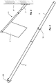
Fig. 2 shows the flagpole ofFig. 1 in a three-dimensional view, -
Fig. 3 shows a longitudinal cross-section of the flagpole ofFig. 1 . - A
pole 1 for aflag 2 is intended to be fixed to apole holder 3, which is mounted on an external wall 4 of a building or similar. Here, a first free end of thepole 1 is intended for cooperation with the saidpole holder 3 while the opposite end of thepole 1 is intended for holding theflag 2. - The said
pole 1 according to the invention comprises at least two longitudinally connectedtubes first tube 5 is fixed and intended to cooperate with thepole holder 3, whereas asecond tube 6 is intended to receive theflag 2 and rotate about the longitudinal axis of thepole 1 relative to thefirst tube 5. The length of eachtube tubes - Rotating the
tubes tube tube tube - The said
tubes pole 8, which extends through the corresponding hole of the respective bearing means 7 along at least one part of thepole 1 length. The said connectingpole 8 is formed at least on its first far end, which lies in the area ofpole 1 intended for holding theflag 2, with a threaded means 9, e.g., a threaded protrusion, which is intended for cooperation with an opposite threadedmeans 10, e.g., a nut. Furthermore, the present invention provides for that sections of the said connectingpole 8 extends piecewise inside asleeve 11, which holds the said bearing means 7 at a fixed distance from one another. The connectingpole 1 may be fixed inside thefirst tube 5 by means of the said bearing means 7; alternatively, it can be inserted and fixed firmly in thefirst tube 5, e.g., by means of a shrink joint. - The
second tube 6, which is intended to hold the flag, comprises on its free end, i.e., the end facing away from thefirst tube 5, anend element 12, which is, for example, designed as a sphere, tip, or similar. The saidend element 12 is, for example, firmly connected by means of a threaded joint to the threaded means 9 of the connectingpole 8. Furthermore, theend element 12, is formed on the side facing the free end of thesecond tube 6 with aflange 13, which is intended as a first drip-off element to prevent water dripping down theflagpole 1. Furthermore, theend element 12 is formed in the extension of theflange 13 and in the longitudinal direction of thepole 1 towards thetube 5 with acover element 14, which is impermeable to water and surrounds and closes off the said free end of thesecond tube 6. An embodiment is possible according to the present invention with the saidcover element 14 formed as a standalone element located between theend element 12 or theflange 13 thereof. - Furthermore, the present invention provides for that the
pole 1 for aflag 2 comprises at least one additional drip-offelement 15, which is located in the area of the third of thefirst tube 5, which cooperates with the saidpole holder 3. The additional drip-offelement 15 may be, for example, formed as a protrusion extending at least partly around the circumference and approximately perpendicular to thefirst tube 5. Furthermore, the additional drip-offelement 15 may be, for example, formed in a sense of an element comprising several threads of a helix, which is wrapped around the circumference of the first tube. The helix-shaped drip-offelement 15 may be selected as a compression spring in a form of a metal strip or a wire with a circular cross-section, and similar.
Claims (12)
- A flagpole, preferably a rigid flagpole, which can be mounted onto the external wall of a building or similar, characterized in that it comprises at least two longitudinally connected first tube (5) and second tube (6), arranged to rotate against each other, whereby the ability of the tubes (5, 6) to rotate against each other is achieved by one, preferably at least two, optionally more, bearing means (7), which are fixed individually or in pairs longitudinally inside each of the tubes (5, 6), which are mutually fixed in position by means of a connecting pole (8) extending approximately along at least a part of the length of the pole (1), whereby the second tube (6) comprises at its free end an end element (12) formed with a flange (13), and whereby the pole (1) comprises at least one additional drip-off element (15).
- A flagpole according to claim 1, characterized in that the first tube (5) is stationary and intended to cooperate with the pole holder (3), while the second tube (6) is intended to hold the flag (2) and rotate longitudinally in the direction of the pole (1) relative to the first tube (5).
- A flagpole according to any of the preceding claims, characterized in that the said connecting pole (8) is formed on at least one of its far ends with a threaded means (9), which is intended to cooperate with the opposite threaded means (10), whereby the connecting pole (8) extends piecewise inside a sleeve (11) that holds the bearing means (7) at a fixed distance from one another.
- A flagpole according to any of the preceding claims, characterized in that the said connecting pole (8) in the first tube (5) can be firmly fixed, e.g., with a shrink joint.
- A flagpole according to any of the preceding claims, characterized in that each bearing means (7) is selected as a sliding bearing, rolling bearing, or similar, and is located in each tube (5, 6) in each far end area of the tube (5, 6).
- A flagpole according to any of the preceding claims, characterized in that the said end element (12) can be firmly connected by means of a threaded joint to the threaded means (9) of the connecting pole (8).
- A flagpole according to any of the preceding claims, characterized in that the flange (13) of the end element (12) is provided as a first drip-off element to prevent water from dripping down the flagpole (1).
- A flagpole according to any of the preceding claims, characterized in that the end element (12) in the extension of the flange (13) comprises a cover element (14), which is impermeable to water and surrounds and closes off the free end of the second tube (6).
- A flagpole according to claim 8, characterized in that the said cover element (14) is designed as a stand-alone element.
- A flagpole according to any of the preceding claims, characterized in that the additional drip-off element (15) is located in the area of the third of the first tube (5), which cooperates with the said pole holder (3).
- A flagpole according to claim 10, characterized in that the additional drip-off element (15) can be formed as a protrusion extending at least partly around the circumference and approximately perpendicular to the first tube (5).
- A flagpole according to claim 10, characterized in that the additional drip-off element (15) can be designed as an element comprising several threads of a helix, which is wrapped around the circumference of the first tube (5).
Applications Claiming Priority (1)
| Application Number | Priority Date | Filing Date | Title |
|---|---|---|---|
| SI202100117 | 2021-06-09 |
Publications (2)
| Publication Number | Publication Date |
|---|---|
| EP4102009A1 true EP4102009A1 (en) | 2022-12-14 |
| EP4102009B1 EP4102009B1 (en) | 2025-11-05 |
Family
ID=81877830
Family Applications (1)
| Application Number | Title | Priority Date | Filing Date |
|---|---|---|---|
| EP22175703.2A Active EP4102009B1 (en) | 2021-06-09 | 2022-05-27 | Flagpole |
Country Status (1)
| Country | Link |
|---|---|
| EP (1) | EP4102009B1 (en) |
Citations (3)
| Publication number | Priority date | Publication date | Assignee | Title |
|---|---|---|---|---|
| US4918896A (en) * | 1988-10-17 | 1990-04-24 | Harold Wiese | Telescopic flagpole |
| US5005512A (en) * | 1990-03-29 | 1991-04-09 | Fu Shan C | Portable extensible flag pole with a flag |
| US5363607A (en) * | 1994-01-26 | 1994-11-15 | Turturro Nicholas A | Flagpole and cap |
-
2022
- 2022-05-27 EP EP22175703.2A patent/EP4102009B1/en active Active
Patent Citations (3)
| Publication number | Priority date | Publication date | Assignee | Title |
|---|---|---|---|---|
| US4918896A (en) * | 1988-10-17 | 1990-04-24 | Harold Wiese | Telescopic flagpole |
| US5005512A (en) * | 1990-03-29 | 1991-04-09 | Fu Shan C | Portable extensible flag pole with a flag |
| US5363607A (en) * | 1994-01-26 | 1994-11-15 | Turturro Nicholas A | Flagpole and cap |
Also Published As
| Publication number | Publication date |
|---|---|
| EP4102009B1 (en) | 2025-11-05 |
Similar Documents
| Publication | Publication Date | Title |
|---|---|---|
| CA2570309A1 (en) | Electrical contact technology and methodology for the manufacture of large-diameter electrical slip rings | |
| JPS5936486B2 (en) | Drawer assembly used for communication cables | |
| EP4102009B1 (en) | Flagpole | |
| US20100084621A1 (en) | Wire Guiding Device | |
| JP2012523065A5 (en) | ||
| US20120071018A1 (en) | Connector with a blade, tool for actuating said connector, kit and fire detector comprising same | |
| JP2009118565A (en) | Cross arm installation reinforcing tool | |
| JP5403499B2 (en) | Anticorrosion structure of steel structure | |
| US7823361B2 (en) | Conduit holder for use with a metal stud | |
| ES2592323B1 (en) | Lightning receiver for a wind turbine blade | |
| US20110123320A1 (en) | Arrangement with a Nacelle and with an Instrument | |
| KR200477358Y1 (en) | Clamp for grounding of arc welding machine | |
| SI26216A (en) | FLAG DRUG | |
| JP4315383B2 (en) | Cable support | |
| RU2019115079A (en) | FLEXIBLE PIPE | |
| US20040103501A1 (en) | Apparatus and method for clamping cable | |
| JP2007282428A (en) | Anchor structure of overhead insulated wire | |
| JP6920692B2 (en) | Conduit support | |
| CN222382540U (en) | Bird thorn strip is firmly installed for electric power system | |
| CH689876A5 (en) | Temperature sensor with capillary pipe system e.g. for flue or exhaust gases | |
| JP3008765U (en) | Fixing for lashing rod | |
| JP5116621B2 (en) | Danger flag | |
| US20060288542A1 (en) | One-piece cable armor ferrule | |
| JP5845854B2 (en) | Steel pipe inner side full length marking device | |
| JP5020108B2 (en) | Branch adapter for tension clamp |
Legal Events
| Date | Code | Title | Description |
|---|---|---|---|
| PUAI | Public reference made under article 153(3) epc to a published international application that has entered the european phase |
Free format text: ORIGINAL CODE: 0009012 |
|
| STAA | Information on the status of an ep patent application or granted ep patent |
Free format text: STATUS: THE APPLICATION HAS BEEN PUBLISHED |
|
| AK | Designated contracting states |
Kind code of ref document: A1 Designated state(s): AL AT BE BG CH CY CZ DE DK EE ES FI FR GB GR HR HU IE IS IT LI LT LU LV MC MK MT NL NO PL PT RO RS SE SI SK SM TR |
|
| STAA | Information on the status of an ep patent application or granted ep patent |
Free format text: STATUS: REQUEST FOR EXAMINATION WAS MADE |
|
| 17P | Request for examination filed |
Effective date: 20230614 |
|
| RBV | Designated contracting states (corrected) |
Designated state(s): AL AT BE BG CH CY CZ DE DK EE ES FI FR GB GR HR HU IE IS IT LI LT LU LV MC MK MT NL NO PL PT RO RS SE SI SK SM TR |
|
| GRAP | Despatch of communication of intention to grant a patent |
Free format text: ORIGINAL CODE: EPIDOSNIGR1 |
|
| STAA | Information on the status of an ep patent application or granted ep patent |
Free format text: STATUS: GRANT OF PATENT IS INTENDED |
|
| INTG | Intention to grant announced |
Effective date: 20250807 |
|
| GRAS | Grant fee paid |
Free format text: ORIGINAL CODE: EPIDOSNIGR3 |
|
| GRAA | (expected) grant |
Free format text: ORIGINAL CODE: 0009210 |
|
| STAA | Information on the status of an ep patent application or granted ep patent |
Free format text: STATUS: THE PATENT HAS BEEN GRANTED |
|
| AK | Designated contracting states |
Kind code of ref document: B1 Designated state(s): AL AT BE BG CH CY CZ DE DK EE ES FI FR GB GR HR HU IE IS IT LI LT LU LV MC MK MT NL NO PL PT RO RS SE SI SK SM TR |
|
| REG | Reference to a national code |
Ref country code: CH Ref legal event code: F10 Free format text: ST27 STATUS EVENT CODE: U-0-0-F10-F00 (AS PROVIDED BY THE NATIONAL OFFICE) Effective date: 20251105 Ref country code: GB Ref legal event code: FG4D |
|
| REG | Reference to a national code |
Ref country code: DE Ref legal event code: R096 Ref document number: 602022024277 Country of ref document: DE |
|
| REG | Reference to a national code |
Ref country code: IE Ref legal event code: FG4D |
|
| U01 | Request for unitary effect filed |
Effective date: 20251209 |
|
| U50 | Request for re-establishment of rights filed [unitary effect] |
Free format text: RE-ESTABLISHMENT OF RIGHTS REQUESTED DUE TO A LATE FILING ON THE REQUEST FOR UNITARY EFFECT Effective date: 20251209 |
|
| REG | Reference to a national code |
Ref country code: NL Ref legal event code: MP Effective date: 20251105 |
|
| PG25 | Lapsed in a contracting state [announced via postgrant information from national office to epo] |
Ref country code: ES Free format text: LAPSE BECAUSE OF FAILURE TO SUBMIT A TRANSLATION OF THE DESCRIPTION OR TO PAY THE FEE WITHIN THE PRESCRIBED TIME-LIMIT Effective date: 20251105 |
|
| REG | Reference to a national code |
Ref country code: LT Ref legal event code: MG9D |
|
| PG25 | Lapsed in a contracting state [announced via postgrant information from national office to epo] |
Ref country code: NO Free format text: LAPSE BECAUSE OF FAILURE TO SUBMIT A TRANSLATION OF THE DESCRIPTION OR TO PAY THE FEE WITHIN THE PRESCRIBED TIME-LIMIT Effective date: 20260205 |
|
| PG25 | Lapsed in a contracting state [announced via postgrant information from national office to epo] |
Ref country code: HR Free format text: LAPSE BECAUSE OF FAILURE TO SUBMIT A TRANSLATION OF THE DESCRIPTION OR TO PAY THE FEE WITHIN THE PRESCRIBED TIME-LIMIT Effective date: 20251105 Ref country code: FI Free format text: LAPSE BECAUSE OF FAILURE TO SUBMIT A TRANSLATION OF THE DESCRIPTION OR TO PAY THE FEE WITHIN THE PRESCRIBED TIME-LIMIT Effective date: 20251105 |
|
| PG25 | Lapsed in a contracting state [announced via postgrant information from national office to epo] |
Ref country code: NL Free format text: LAPSE BECAUSE OF FAILURE TO SUBMIT A TRANSLATION OF THE DESCRIPTION OR TO PAY THE FEE WITHIN THE PRESCRIBED TIME-LIMIT Effective date: 20251105 |
|
| PG25 | Lapsed in a contracting state [announced via postgrant information from national office to epo] |
Ref country code: RS Free format text: LAPSE BECAUSE OF FAILURE TO SUBMIT A TRANSLATION OF THE DESCRIPTION OR TO PAY THE FEE WITHIN THE PRESCRIBED TIME-LIMIT Effective date: 20260205 |
|
| PG25 | Lapsed in a contracting state [announced via postgrant information from national office to epo] |
Ref country code: IS Free format text: LAPSE BECAUSE OF FAILURE TO SUBMIT A TRANSLATION OF THE DESCRIPTION OR TO PAY THE FEE WITHIN THE PRESCRIBED TIME-LIMIT Effective date: 20260305 |
|
| PG25 | Lapsed in a contracting state [announced via postgrant information from national office to epo] |
Ref country code: PT Free format text: LAPSE BECAUSE OF FAILURE TO SUBMIT A TRANSLATION OF THE DESCRIPTION OR TO PAY THE FEE WITHIN THE PRESCRIBED TIME-LIMIT Effective date: 20260305 |
|
| PG25 | Lapsed in a contracting state [announced via postgrant information from national office to epo] |
Ref country code: PL Free format text: LAPSE BECAUSE OF FAILURE TO SUBMIT A TRANSLATION OF THE DESCRIPTION OR TO PAY THE FEE WITHIN THE PRESCRIBED TIME-LIMIT Effective date: 20251105 |
|
| U52 | Request for re-establishment of rights deleted [unitary effect] |
Effective date: 20260326 |
|
| PG25 | Lapsed in a contracting state [announced via postgrant information from national office to epo] |
Ref country code: BG Free format text: LAPSE BECAUSE OF FAILURE TO SUBMIT A TRANSLATION OF THE DESCRIPTION OR TO PAY THE FEE WITHIN THE PRESCRIBED TIME-LIMIT Effective date: 20251105 |
|
| PG25 | Lapsed in a contracting state [announced via postgrant information from national office to epo] |
Ref country code: LT Free format text: LAPSE BECAUSE OF FAILURE TO SUBMIT A TRANSLATION OF THE DESCRIPTION OR TO PAY THE FEE WITHIN THE PRESCRIBED TIME-LIMIT Effective date: 20251105 |
|
| PG25 | Lapsed in a contracting state [announced via postgrant information from national office to epo] |
Ref country code: SM Free format text: LAPSE BECAUSE OF FAILURE TO SUBMIT A TRANSLATION OF THE DESCRIPTION OR TO PAY THE FEE WITHIN THE PRESCRIBED TIME-LIMIT Effective date: 20251105 |
|
| U04 | Request for unitary effect rejected |
Effective date: 20260603 |
|
| PG25 | Lapsed in a contracting state [announced via postgrant information from national office to epo] |
Ref country code: DK Free format text: LAPSE BECAUSE OF FAILURE TO SUBMIT A TRANSLATION OF THE DESCRIPTION OR TO PAY THE FEE WITHIN THE PRESCRIBED TIME-LIMIT Effective date: 20251105 |
|
| PG25 | Lapsed in a contracting state [announced via postgrant information from national office to epo] |
Ref country code: IT Free format text: LAPSE BECAUSE OF FAILURE TO SUBMIT A TRANSLATION OF THE DESCRIPTION OR TO PAY THE FEE WITHIN THE PRESCRIBED TIME-LIMIT Effective date: 20251105 |
|
| PGFP | Annual fee paid to national office [announced via postgrant information from national office to epo] |
Ref country code: AT Payment date: 20260714 Year of fee payment: 5 |
|
| PG25 | Lapsed in a contracting state [announced via postgrant information from national office to epo] |
Ref country code: EE Free format text: LAPSE BECAUSE OF FAILURE TO SUBMIT A TRANSLATION OF THE DESCRIPTION OR TO PAY THE FEE WITHIN THE PRESCRIBED TIME-LIMIT Effective date: 20251105 |
|
| PG25 | Lapsed in a contracting state [announced via postgrant information from national office to epo] |
Ref country code: CZ Free format text: LAPSE BECAUSE OF FAILURE TO SUBMIT A TRANSLATION OF THE DESCRIPTION OR TO PAY THE FEE WITHIN THE PRESCRIBED TIME-LIMIT Effective date: 20251105 |
|
| PG25 | Lapsed in a contracting state [announced via postgrant information from national office to epo] |
Ref country code: SK Free format text: LAPSE BECAUSE OF FAILURE TO SUBMIT A TRANSLATION OF THE DESCRIPTION OR TO PAY THE FEE WITHIN THE PRESCRIBED TIME-LIMIT Effective date: 20251105 |
|
| PG25 | Lapsed in a contracting state [announced via postgrant information from national office to epo] |
Ref country code: SE Free format text: LAPSE BECAUSE OF FAILURE TO SUBMIT A TRANSLATION OF THE DESCRIPTION OR TO PAY THE FEE WITHIN THE PRESCRIBED TIME-LIMIT Effective date: 20251105 |