EP4101943A1 - Coating for a substrate - Google Patents
Coating for a substrate Download PDFInfo
- Publication number
- EP4101943A1 EP4101943A1 EP22177061.3A EP22177061A EP4101943A1 EP 4101943 A1 EP4101943 A1 EP 4101943A1 EP 22177061 A EP22177061 A EP 22177061A EP 4101943 A1 EP4101943 A1 EP 4101943A1
- Authority
- EP
- European Patent Office
- Prior art keywords
- ferrite
- coating
- substrate
- concentration
- carbon
- Prior art date
- Legal status (The legal status is an assumption and is not a legal conclusion. Google has not performed a legal analysis and makes no representation as to the accuracy of the status listed.)
- Withdrawn
Links
- 239000011248 coating agent Substances 0.000 title claims abstract description 92
- 238000000576 coating method Methods 0.000 title claims abstract description 92
- 239000000758 substrate Substances 0.000 title claims abstract description 42
- 229910000859 α-Fe Inorganic materials 0.000 claims abstract description 110
- OKTJSMMVPCPJKN-UHFFFAOYSA-N Carbon Chemical compound [C] OKTJSMMVPCPJKN-UHFFFAOYSA-N 0.000 claims abstract description 79
- 229910052799 carbon Inorganic materials 0.000 claims abstract description 49
- ZAUUZASCMSWKGX-UHFFFAOYSA-N manganese nickel Chemical compound [Mn].[Ni] ZAUUZASCMSWKGX-UHFFFAOYSA-N 0.000 claims abstract description 45
- 229910021393 carbon nanotube Inorganic materials 0.000 claims abstract description 34
- 239000002041 carbon nanotube Substances 0.000 claims abstract description 34
- 229920002379 silicone rubber Polymers 0.000 claims abstract description 17
- 239000004944 Liquid Silicone Rubber Substances 0.000 claims abstract description 14
- 238000010411 cooking Methods 0.000 claims description 11
- 238000000034 method Methods 0.000 abstract description 22
- 239000000203 mixture Substances 0.000 description 17
- 238000009472 formulation Methods 0.000 description 13
- 239000000463 material Substances 0.000 description 5
- 230000008569 process Effects 0.000 description 4
- 238000009792 diffusion process Methods 0.000 description 3
- 238000012986 modification Methods 0.000 description 3
- 230000004048 modification Effects 0.000 description 3
- 239000004480 active ingredient Substances 0.000 description 2
- 230000008901 benefit Effects 0.000 description 2
- 238000004140 cleaning Methods 0.000 description 2
- 239000003086 colorant Substances 0.000 description 2
- 238000010276 construction Methods 0.000 description 2
- 239000012530 fluid Substances 0.000 description 2
- 238000010438 heat treatment Methods 0.000 description 2
- 238000011012 sanitization Methods 0.000 description 2
- 238000010521 absorption reaction Methods 0.000 description 1
- 239000000654 additive Substances 0.000 description 1
- 230000000712 assembly Effects 0.000 description 1
- 238000000429 assembly Methods 0.000 description 1
- 239000004020 conductor Substances 0.000 description 1
- 230000008878 coupling Effects 0.000 description 1
- 238000010168 coupling process Methods 0.000 description 1
- 238000005859 coupling reaction Methods 0.000 description 1
- 238000010586 diagram Methods 0.000 description 1
- 229920001971 elastomer Polymers 0.000 description 1
- 239000000806 elastomer Substances 0.000 description 1
- 239000007769 metal material Substances 0.000 description 1
- 238000006467 substitution reaction Methods 0.000 description 1
- 230000007704 transition Effects 0.000 description 1
- XLYOFNOQVPJJNP-UHFFFAOYSA-N water Substances O XLYOFNOQVPJJNP-UHFFFAOYSA-N 0.000 description 1
Images
Classifications
-
- C—CHEMISTRY; METALLURGY
- C04—CEMENTS; CONCRETE; ARTIFICIAL STONE; CERAMICS; REFRACTORIES
- C04B—LIME, MAGNESIA; SLAG; CEMENTS; COMPOSITIONS THEREOF, e.g. MORTARS, CONCRETE OR LIKE BUILDING MATERIALS; ARTIFICIAL STONE; CERAMICS; REFRACTORIES; TREATMENT OF NATURAL STONE
- C04B26/00—Compositions of mortars, concrete or artificial stone, containing only organic binders, e.g. polymer or resin concrete
- C04B26/30—Compounds having one or more carbon-to-metal or carbon-to-silicon linkages ; Other silicon-containing organic compounds; Boron-organic compounds
- C04B26/32—Compounds having one or more carbon-to-metal or carbon-to-silicon linkages ; Other silicon-containing organic compounds; Boron-organic compounds containing silicon
-
- C—CHEMISTRY; METALLURGY
- C09—DYES; PAINTS; POLISHES; NATURAL RESINS; ADHESIVES; COMPOSITIONS NOT OTHERWISE PROVIDED FOR; APPLICATIONS OF MATERIALS NOT OTHERWISE PROVIDED FOR
- C09D—COATING COMPOSITIONS, e.g. PAINTS, VARNISHES OR LACQUERS; FILLING PASTES; CHEMICAL PAINT OR INK REMOVERS; INKS; CORRECTING FLUIDS; WOODSTAINS; PASTES OR SOLIDS FOR COLOURING OR PRINTING; USE OF MATERIALS THEREFOR
- C09D183/00—Coating compositions based on macromolecular compounds obtained by reactions forming in the main chain of the macromolecule a linkage containing silicon, with or without sulfur, nitrogen, oxygen, or carbon only; Coating compositions based on derivatives of such polymers
- C09D183/04—Polysiloxanes
-
- C—CHEMISTRY; METALLURGY
- C23—COATING METALLIC MATERIAL; COATING MATERIAL WITH METALLIC MATERIAL; CHEMICAL SURFACE TREATMENT; DIFFUSION TREATMENT OF METALLIC MATERIAL; COATING BY VACUUM EVAPORATION, BY SPUTTERING, BY ION IMPLANTATION OR BY CHEMICAL VAPOUR DEPOSITION, IN GENERAL; INHIBITING CORROSION OF METALLIC MATERIAL OR INCRUSTATION IN GENERAL
- C23C—COATING METALLIC MATERIAL; COATING MATERIAL WITH METALLIC MATERIAL; SURFACE TREATMENT OF METALLIC MATERIAL BY DIFFUSION INTO THE SURFACE, BY CHEMICAL CONVERSION OR SUBSTITUTION; COATING BY VACUUM EVAPORATION, BY SPUTTERING, BY ION IMPLANTATION OR BY CHEMICAL VAPOUR DEPOSITION, IN GENERAL
- C23C28/00—Coating for obtaining at least two superposed coatings either by methods not provided for in a single one of groups C23C2/00 - C23C26/00 or by combinations of methods provided for in subclasses C23C and C25C or C25D
-
- C—CHEMISTRY; METALLURGY
- C09—DYES; PAINTS; POLISHES; NATURAL RESINS; ADHESIVES; COMPOSITIONS NOT OTHERWISE PROVIDED FOR; APPLICATIONS OF MATERIALS NOT OTHERWISE PROVIDED FOR
- C09D—COATING COMPOSITIONS, e.g. PAINTS, VARNISHES OR LACQUERS; FILLING PASTES; CHEMICAL PAINT OR INK REMOVERS; INKS; CORRECTING FLUIDS; WOODSTAINS; PASTES OR SOLIDS FOR COLOURING OR PRINTING; USE OF MATERIALS THEREFOR
- C09D5/00—Coating compositions, e.g. paints, varnishes or lacquers, characterised by their physical nature or the effects produced; Filling pastes
- C09D5/24—Electrically-conducting paints
-
- C—CHEMISTRY; METALLURGY
- C09—DYES; PAINTS; POLISHES; NATURAL RESINS; ADHESIVES; COMPOSITIONS NOT OTHERWISE PROVIDED FOR; APPLICATIONS OF MATERIALS NOT OTHERWISE PROVIDED FOR
- C09D—COATING COMPOSITIONS, e.g. PAINTS, VARNISHES OR LACQUERS; FILLING PASTES; CHEMICAL PAINT OR INK REMOVERS; INKS; CORRECTING FLUIDS; WOODSTAINS; PASTES OR SOLIDS FOR COLOURING OR PRINTING; USE OF MATERIALS THEREFOR
- C09D7/00—Features of coating compositions, not provided for in group C09D5/00; Processes for incorporating ingredients in coating compositions
- C09D7/40—Additives
- C09D7/60—Additives non-macromolecular
- C09D7/61—Additives non-macromolecular inorganic
-
- C—CHEMISTRY; METALLURGY
- C09—DYES; PAINTS; POLISHES; NATURAL RESINS; ADHESIVES; COMPOSITIONS NOT OTHERWISE PROVIDED FOR; APPLICATIONS OF MATERIALS NOT OTHERWISE PROVIDED FOR
- C09D—COATING COMPOSITIONS, e.g. PAINTS, VARNISHES OR LACQUERS; FILLING PASTES; CHEMICAL PAINT OR INK REMOVERS; INKS; CORRECTING FLUIDS; WOODSTAINS; PASTES OR SOLIDS FOR COLOURING OR PRINTING; USE OF MATERIALS THEREFOR
- C09D7/00—Features of coating compositions, not provided for in group C09D5/00; Processes for incorporating ingredients in coating compositions
- C09D7/40—Additives
- C09D7/70—Additives characterised by shape, e.g. fibres, flakes or microspheres
-
- C—CHEMISTRY; METALLURGY
- C09—DYES; PAINTS; POLISHES; NATURAL RESINS; ADHESIVES; COMPOSITIONS NOT OTHERWISE PROVIDED FOR; APPLICATIONS OF MATERIALS NOT OTHERWISE PROVIDED FOR
- C09D—COATING COMPOSITIONS, e.g. PAINTS, VARNISHES OR LACQUERS; FILLING PASTES; CHEMICAL PAINT OR INK REMOVERS; INKS; CORRECTING FLUIDS; WOODSTAINS; PASTES OR SOLIDS FOR COLOURING OR PRINTING; USE OF MATERIALS THEREFOR
- C09D7/00—Features of coating compositions, not provided for in group C09D5/00; Processes for incorporating ingredients in coating compositions
- C09D7/80—Processes for incorporating ingredients
-
- C—CHEMISTRY; METALLURGY
- C23—COATING METALLIC MATERIAL; COATING MATERIAL WITH METALLIC MATERIAL; CHEMICAL SURFACE TREATMENT; DIFFUSION TREATMENT OF METALLIC MATERIAL; COATING BY VACUUM EVAPORATION, BY SPUTTERING, BY ION IMPLANTATION OR BY CHEMICAL VAPOUR DEPOSITION, IN GENERAL; INHIBITING CORROSION OF METALLIC MATERIAL OR INCRUSTATION IN GENERAL
- C23C—COATING METALLIC MATERIAL; COATING MATERIAL WITH METALLIC MATERIAL; SURFACE TREATMENT OF METALLIC MATERIAL BY DIFFUSION INTO THE SURFACE, BY CHEMICAL CONVERSION OR SUBSTITUTION; COATING BY VACUUM EVAPORATION, BY SPUTTERING, BY ION IMPLANTATION OR BY CHEMICAL VAPOUR DEPOSITION, IN GENERAL
- C23C26/00—Coating not provided for in groups C23C2/00 - C23C24/00
-
- C—CHEMISTRY; METALLURGY
- C23—COATING METALLIC MATERIAL; COATING MATERIAL WITH METALLIC MATERIAL; CHEMICAL SURFACE TREATMENT; DIFFUSION TREATMENT OF METALLIC MATERIAL; COATING BY VACUUM EVAPORATION, BY SPUTTERING, BY ION IMPLANTATION OR BY CHEMICAL VAPOUR DEPOSITION, IN GENERAL; INHIBITING CORROSION OF METALLIC MATERIAL OR INCRUSTATION IN GENERAL
- C23C—COATING METALLIC MATERIAL; COATING MATERIAL WITH METALLIC MATERIAL; SURFACE TREATMENT OF METALLIC MATERIAL BY DIFFUSION INTO THE SURFACE, BY CHEMICAL CONVERSION OR SUBSTITUTION; COATING BY VACUUM EVAPORATION, BY SPUTTERING, BY ION IMPLANTATION OR BY CHEMICAL VAPOUR DEPOSITION, IN GENERAL
- C23C30/00—Coating with metallic material characterised only by the composition of the metallic material, i.e. not characterised by the coating process
-
- H—ELECTRICITY
- H05—ELECTRIC TECHNIQUES NOT OTHERWISE PROVIDED FOR
- H05B—ELECTRIC HEATING; ELECTRIC LIGHT SOURCES NOT OTHERWISE PROVIDED FOR; CIRCUIT ARRANGEMENTS FOR ELECTRIC LIGHT SOURCES, IN GENERAL
- H05B3/00—Ohmic-resistance heating
- H05B3/10—Heating elements characterised by the composition or nature of the materials or by the arrangement of the conductor
- H05B3/12—Heating elements characterised by the composition or nature of the materials or by the arrangement of the conductor characterised by the composition or nature of the conductive material
-
- H—ELECTRICITY
- H05—ELECTRIC TECHNIQUES NOT OTHERWISE PROVIDED FOR
- H05B—ELECTRIC HEATING; ELECTRIC LIGHT SOURCES NOT OTHERWISE PROVIDED FOR; CIRCUIT ARRANGEMENTS FOR ELECTRIC LIGHT SOURCES, IN GENERAL
- H05B3/00—Ohmic-resistance heating
- H05B3/10—Heating elements characterised by the composition or nature of the materials or by the arrangement of the conductor
- H05B3/12—Heating elements characterised by the composition or nature of the materials or by the arrangement of the conductor characterised by the composition or nature of the conductive material
- H05B3/14—Heating elements characterised by the composition or nature of the materials or by the arrangement of the conductor characterised by the composition or nature of the conductive material the material being non-metallic
- H05B3/145—Carbon only, e.g. carbon black, graphite
-
- A—HUMAN NECESSITIES
- A47—FURNITURE; DOMESTIC ARTICLES OR APPLIANCES; COFFEE MILLS; SPICE MILLS; SUCTION CLEANERS IN GENERAL
- A47J—KITCHEN EQUIPMENT; COFFEE MILLS; SPICE MILLS; APPARATUS FOR MAKING BEVERAGES
- A47J36/00—Parts, details or accessories of cooking-vessels
- A47J36/02—Selection of specific materials, e.g. heavy bottoms with copper inlay or with insulating inlay
-
- C—CHEMISTRY; METALLURGY
- C04—CEMENTS; CONCRETE; ARTIFICIAL STONE; CERAMICS; REFRACTORIES
- C04B—LIME, MAGNESIA; SLAG; CEMENTS; COMPOSITIONS THEREOF, e.g. MORTARS, CONCRETE OR LIKE BUILDING MATERIALS; ARTIFICIAL STONE; CERAMICS; REFRACTORIES; TREATMENT OF NATURAL STONE
- C04B2111/00—Mortars, concrete or artificial stone or mixtures to prepare them, characterised by specific function, property or use
- C04B2111/00474—Uses not provided for elsewhere in C04B2111/00
- C04B2111/00482—Coating or impregnation materials
Definitions
- the present device relates to a coating. More specifically, the present device relates to a coating for a substrate.
- a coating for a substrate includes a first portion and a second portion.
- the first portion includes a first liquid silicone rubber, carbon nanotubes, and at least one ferrite-containing component chosen from carbon ferrite and nickel manganese ferrite.
- the carbon nanotubes in the first portion are at a concentration of at least about 0.5% by weight of the first portion.
- the second portion includes a second liquid silicone rubber, carbon nanotubes, and at least one ferrite-containing component chosen from carbon ferrite and nickel manganese ferrite.
- the carbon nanotubes in the second portion are at a concentration of at least about 0.5% by weight of the second portion.
- a coating for a substrate includes a first portion and a second portion.
- the first portion includes a first liquid silicone rubber, carbon nanotubes, carbon ferrite, and nickel manganese ferrite.
- the carbon nanotubes in the first portion are present at a concentration of at least about 0.5% by weight of the first portion.
- the second portion includes a second liquid silicone rubber, carbon nanotubes, carbon ferrite, and nickel manganese ferrite.
- the carbon nanotubes in the second portion are present at a concentration of at least about 0.5% by weight of the second portion.
- a method of forming a coating for a substrate includes mixing a first liquid silicone rubber, carbon nanotubes, carbon ferrite, and nickel manganese ferrite at a speed of at least about 1650 rpm for a duration of about one minute to form a first portion of the coating.
- the carbon nanotubes are present in the first portion at a concentration of at least about 0.5% by weight of the first portion.
- the method also includes mixing a second liquid silicone rubber, carbon nanotubes, carbon ferrite, and nickel manganese ferrite at a speed of at least about 1650 rpm for a duration of about one minute to form a second portion of the coating.
- the carbon nanotubes are present in the second portion at a concentration of at least about 0.5% by weight of the second portion.
- the method further includes mixing the first portion and the second portion together at a speed of less than about 1650 rpm for a duration of at least one minute to create an uncured coating. Additionally, the method includes applying the uncured coating to the substrate. Further, the method includes curing the uncured coating to form the coating on the substrate.
- the present illustrated embodiments reside primarily in combinations of method steps and apparatus components related to a cooking appliance door push button assembly. Accordingly, the apparatus components and method steps have been represented, where appropriate, by conventional symbols in the drawings, showing only those specific details that are pertinent to understanding the embodiments of the present disclosure so as not to obscure the disclosure with details that will be readily apparent to those of ordinary skill in the art having the benefit of the description herein. Further, like numerals in the description and drawings represent like elements.
- the terms “upper,” “lower,” “right,” “left,” “rear,” “front,” “vertical,” “horizontal,” and derivatives thereof shall relate to the disclosure as oriented in FIG. 1 .
- the term “front” shall refer to the surface of the element closer to an intended viewer, and the term “rear” shall refer to the surface of the element further from the intended viewer.
- the disclosure may assume various alternative orientations, except where expressly specified to the contrary.
- the specific devices and processes illustrated in the attached drawings, and described in the following specification are simply exemplary embodiments of the inventive concepts defined in the appended claims. Hence, specific dimensions and other physical characteristics relating to the embodiments disclosed herein are not to be considered as limiting, unless the claims expressly state otherwise.
- the term "and/or,” when used in a list of two or more items, means that any one of the listed items can be employed by itself, or any combination of two or more of the listed items, can be employed.
- the composition can contain A alone; B alone; C alone; A and B in combination; A and C in combination; B and C in combination; or A, B, and C in combination.
- a substrate 20 is provided with a coating 24 on at least one surface thereof.
- the coating 24 may be provided on an entirety of available external surfaces of the substrate 20.
- the coating 24 may be provided on less than an entirety of available external surfaces of the substrate 20.
- the coating 24 includes a first portion and a second portion.
- the first portion includes a first liquid silicone rubber, carbon nanotubes, and at least one ferrite-containing component chosen from carbon ferrite and nickel manganese ferrite. Said another way, the first portion can include carbon ferrite and/or nickel manganese ferrite.
- the carbon nanotubes can be present at a concentration of at least about 0.3% by weight of the first portion.
- the carbon nanotubes can be present at a concentration of about 0.3%, about 0.4%, about 0.5%, about 0.6%, about 0.7%, about 0.8%, about 0.9%, about 1.0%, about 1.1%, about 1.2%, about 1.3%, about 1.4%, about 1.5%, about 1.6%, about 1.7%, about 1.8%, about 1.9%, or about 2.0% by weight of the first portion.
- a combined concentration of the carbon ferrite and the nickel manganese ferrite within the first portion can be in a range of about 60% to about 90% by weight of the first portion.
- the carbon ferrite can be present at a concentration of about 20%, about 25%, about 30%, about 35%, or about 40% by weight of the first portion, while the nickel manganese ferrite is present at a concentration of about 40%, about 45%, about 50%, about 55%, about 60%, about 65%, or about 70% by weight of the first portion.
- the second portion includes a second liquid silicone rubber, carbon nanotubes, and at least one ferrite-containing component chosen from carbon ferrite and nickel manganese ferrite.
- the second portion can include carbon ferrite and/or nickel manganese ferrite.
- the carbon nanotubes can be present at a concentration of at least about 0.3% by weight of the second portion.
- the carbon nanotubes can be present at a concentration of about 0.3%, about 0.4%, about 0.5%, about 0.6%, about 0.7%, about 0.8%, about 0.9%, about 1.0%, about 1.1%, about 1.2%, about 1.3%, about 1.4%, about 1.5%, about 1.6%, about 1.7%, about 1.8%, about 1.9%, or about 2.0% by weight of the second portion.
- a combined concentration of the carbon ferrite and the nickel manganese ferrite within the second portion can be in the range of about 60% to about 90% by weight of the second portion.
- the carbon ferrite can be present at a concentration of about 20%, about 25%, about 30%, about 35%, or about 40% by weight of the second portion, while the nickel manganese ferrite is present at a concentration of about 40%, about 45%, about 50%, about 55%, about 60%, about 65%, or about 70% by weight of the second portion.
- the carbon ferrite may be used as the sole ferrite component in the coating 24 or the nickel manganese ferrite may be used as the sole ferrite component in the coating 24. Accordingly, the carbon ferrite may be present at a concentration of about 60% to about 90% by weight of the coating 24.
- the nickel manganese ferrite may be present at a concentration of about 60% to about 90% by weight of the coating 24.
- the substrate 20 and the coating 24 are designed for use within a heated environment of an appliance 28.
- the appliance 28 may be, but is not limited to a microwave oven, an oven, an air fryer, or any other appliance 28 that provides a heated environment to a cavity 32 defined by walls 36 of the appliance 28.
- the substrate 20 and/or the coating 24 may be utilized as a heat-producing component on a hot plate, a crisper plate, a heating element, etc. of a cooking appliance 28.
- the appliance 28 is a microwave oven and the substrate 20 is the surface intended to receive food items to be cooked of a cooking vessel, e.g. a crisper plate.
- the coating 24 is applied onto the surface intended to receive food items to be cooked.
- the crisper plate 20 may be coated with the coating 24, thereby being provided with Accordingly, the composition of the coating 24 is formulated to withstand the heated environment within the cavity 32, as well as the heat provided by the substrate 20 and/or the coating 24. In some examples, the formulation of the coating 24 can be designed to generate heat. For example, components of the coating 24 (e.g., the carbon nanotubes, the carbon ferrite, and/or the nickel manganese ferrite) may be utilized in converting energy of a first type to energy of a second type.
- components of the coating 24 e.g., the carbon nanotubes, the carbon ferrite, and/or the nickel manganese ferrite
- the first type of energy may be electrical energy and the second type of energy may be thermal energy.
- the electrical energy may be converted into the thermal energy as a result of thermo-resistive properties imparted to the coating 24 due to the chosen formulation.
- the first type of energy may be electro-magnetic energy (e.g., microwave energy) and the second type of energy may be thermal energy.
- the electro-magnetic energy may interact with one or more components of the formulation of the coating 24 (e.g., the carbon ferrite and/or the nickel manganese ferrite) to convert the electro-magnetic energy into the thermal energy.
- energy of a third type may be an intermediate step during the transition from the first type of energy to the second type of energy.
- the third type of energy may be kinetic energy (e.g., vibration).
- the coating 24 may exhibit a Curie temperature.
- the Curie temperature is the temperature at which a material begins to lose its magnetic properties. Once the Curie temperature is reached, absorption of the electro-magnetic energy (e.g., microwave energy) ceases and further heating can be prevented. Accordingly, the formulation of the coating 24 can be chosen or designed with a particular operating temperature or a maximum temperature in mind.
- the Curie temperature of the coating 24 can be at least about 300°C.
- the Curie temperature can be at least about 300°C, at least about 350°C, at least about 400°C, at least about 450°C, at least about 500°C, and/or combinations or ranges thereof.
- the formulation of the coating 24 may be chosen such that a plurality of Curie temperatures exists for the coating 24.
- the substrate 20 may be made from a thermally conductive and/or an electrically conductive material (e.g., a metallic material).
- the appliance 28 may include a fan 40, a pump, or a similar device, that can be energized to circulate fluid (e.g., air or water) within the cavity 32 of the appliance 28.
- fluid e.g., air or water
- the pump or similar device could be used in place of the fan 40 based on a particular example of the appliance 28.
- cooking, cleaning, and/or sanitizing operations that are performed by the appliance 28 can be carried out in a manner that is effective and/or efficient.
- the more even distribution or diffusion of heat within the heated environment provided to the cavity 32 can result in more even and reproducible cooking, more effective or efficient cleaning of items within the cavity 32, and/or more effective or efficient sanitization of items within the cavity 32.
- the method 50 includes step 54 of mixing components of the first portion of the coating 24. More specifically, the step 54 can include mixing the first liquid silicone rubber, carbon nanotubes, and at least one ferrite-containing component chosen from carbon ferrite and nickel manganese ferrite at a speed of at least about 1650 rpm for a duration of about one minute to form the first portion of the coating 24.
- the speed of mixing may be about 1650 rpm, about 1700 rpm, about 1750 rpm, about 1800 rpm, about 1850 rpm, about 1900 rpm, about 1950 rpm, about 2000 rpm, and/or combinations or ranges thereof.
- the carbon nanotubes may be present at a concentration of at least about 0.3% by weight of the first portion.
- the carbon nanotubes can be present at a concentration of about 0.3%, about 0.4%, about 0.5%, about 0.6%, about 0.7%, about 0.8%, about 0.9%, about 1.0%, about 1.1%, about 1.2%, about 1.3%, about 1.4%, about 1.5%, about 1.6%, about 1.7%, about 1.8%, about 1.9%, or about 2.0% by weight of the first portion.
- the combined concentration of the carbon ferrite and the nickel manganese ferrite within the first portion can be in the range of about 60% to about 90% by weight of the first portion.
- the carbon ferrite can be present at a concentration of about 20%, about 25%, about 30%, about 35%, or about 40% by weight of the first portion, while the nickel manganese ferrite is present at a concentration of about 40%, about 45%, about 50%, about 55%, about 60%, about 65%, or about 70% by weight of the first portion.
- the method also includes step 58 of mixing the components of the second portion of the coating 24. More specifically, the step 58 can include mixing the second liquid silicone rubber, carbon nanotubes, and at least one ferrite-containing component chosen from carbon ferrite and nickel manganese ferrite at a speed of at least about 1650 rpm for a duration of about one minute to form the second portion of the coating 24.
- the speed of mixing may be about 1650 rpm, about 1700 rpm, about 1750 rpm, about 1800 rpm, about 1850 rpm, about 1900 rpm, about 1950 rpm, about 2000 rpm, and/or combinations or ranges thereof.
- the carbon nanotubes may be present at a concentration of at least about 0.3% by weight of the second portion.
- the carbon nanotubes can be present at a concentration of about 0.3%, about 0.4%, about 0.5%, about 0.6%, about 0.7%, about 0.8%, about 0.9%, about 1.0%, about 1.1%, about 1.2%, about 1.3%, about 1.4%, about 1.5%, about 1.6%, about 1.7%, about 1.8%, about 1.9%, or about 2.0% by weight of the second portion.
- a three-dimensional (3D) bladeless centrifuge speed mixer can be employed in mixing the components of the first portion, mixing the components of the second portion, and/or mixing the first portion and the second portion together.
- the combined concentration of the carbon ferrite and the nickel manganese ferrite within the second portion can be in the range of about 60% to about 90% by weight of the second portion.
- the carbon ferrite can be present at a concentration of about 20%, about 25%, about 30%, about 35%, or about 40% by weight of the second portion, while the nickel manganese ferrite is present at a concentration of about 40%, about 45%, about 50%, about 55%, about 60%, about 65%, or about 70% by weight of the second portion.
- the carbon ferrite may be used as the sole ferrite component in the coating 24 or the nickel manganese ferrite may be used as the sole ferrite component in the coating 24. Accordingly, the carbon ferrite may be present at a concentration of about 60% to about 90% by weight of the coating 24.
- the nickel manganese ferrite may be present at a concentration of about 60% to about 90% by weight of the coating 24.
- the method 50 can further include step 62 of mixing the first portion and the second portion together at a speed of less than about 1650 rpm for a duration of at least about one minute to create an uncured coating.
- the speed of mixing for step 62 may be about 1600 rpm, about 1550 rpm, about 1500 rpm, about 1450 rpm, about 1400 rpm, about 1350 rpm, about 1300 rpm, about 1250 rpm, about 1200 rpm, and/or combinations or ranges thereof.
- the method 50 can additionally include step 66 of applying the uncured coating to the substrate 20. In step 66, the uncured coating may be applied to at least one exterior surface of the substrate 20.
- the method 50 of forming the coating 24 for the substrate 20 may conclude with step 70 of curing the uncured coating to form the coating 24 on the substrate 20.
- the step 70 of curing the uncured coating to form the coating 24 on the substrate 20 can include placing the substrate 20 that has received the uncured coating into a less-than-atmospheric pressure environment.
- the less-than-atmospheric pressure environment may be held at a temperature of about 70°C.
- the substrate 20 with the uncured coating applied thereto may remain in the heated less-than-atmospheric pressure environment for a duration of time that is between about 10 minutes and about 40 minutes.
- the first and second liquid silicone rubbers can be readily mixed with one another and can be rapidly heat-cured into durable elastomers.
- the first portion of the coating 24 may be used for mixing additives (e.g., active ingredients) while the second portion of the coating 24 may be used to adjust a viscosity of the formulation of the coating 24.
- active ingredients to the formulation of the coating 24 can include the carbon nanotubes, the carbon ferrite, and/or the nickel manganese ferrite.
- the formulation of the coating 24 includes the first portion at a concentration of 80% and the second portion at a concentration of 20%.
- the formulation of the coating 24 can be an 80:20 mixture of the first portion and the second portion, respectively.
- the carbon ferrite was present at a concentration of 77.5% by weight of the coating 24, the carbon nanotube were present at a concentration of 2.5% by weight of the coating 24, and the first and second liquid silicone rubbers were present at a total concentration of 20% by weight of the coating 24.
- the nickel manganese ferrite was present at a concentration of 80% by weight of the coating 24, the carbon nanotubes were present at a concentration of 1.5% by weight of the coating 24, and the first and second liquid silicone rubbers were present at a total concentration of 18.5% by weight of the coating 24.
- the term "coupled” in all of its forms, couple, coupling, coupled, etc. generally means the joining of two components (electrical or mechanical) directly or indirectly to one another. Such joining may be stationary in nature or movable in nature. Such joining may be achieved with the two components (electrical or mechanical) and any additional intermediate members being integrally formed as a single unitary body with one another or with the two components. Such joining may be permanent in nature or may be removable or releasable in nature unless otherwise stated.
- elements shown as integrally formed may be constructed of multiple parts or elements shown as multiple parts may be integrally formed, the operation of the interfaces may be reversed or otherwise varied, the length or width of the structures and/or members or connector or other elements of the system may be varied, the nature or number of adjustment positions provided between the elements may be varied.
- the elements and/or assemblies of the system may be constructed from any of a wide variety of materials that provide sufficient strength or durability, in any of a wide variety of colors, textures, and combinations. Accordingly, all such modifications are intended to be included within the scope of the present innovations. Other substitutions, modifications, changes, and omissions may be made in the design, operating conditions, and arrangement of the desired and other exemplary embodiments without departing from the spirit of the present innovations.
Landscapes
- Chemical & Material Sciences (AREA)
- Engineering & Computer Science (AREA)
- Materials Engineering (AREA)
- Organic Chemistry (AREA)
- Life Sciences & Earth Sciences (AREA)
- Wood Science & Technology (AREA)
- Chemical Kinetics & Catalysis (AREA)
- Mechanical Engineering (AREA)
- Metallurgy (AREA)
- Ceramic Engineering (AREA)
- Inorganic Chemistry (AREA)
- Structural Engineering (AREA)
- Paints Or Removers (AREA)
- Cookers (AREA)
Abstract
A coating (24) for a substrate (20) includes a first portion and a second portion. The first portion includes a first liquid silicone rubber, carbon nanotubes at a concentration of at least about 0.5% by weight of the first portion, and at least one ferrite-containing component chosen from carbon ferrite and nickel manganese ferrite. The second portion includes a second liquid silicone rubber, carbon nanotubes at a concentration of at least about 0.5% by weight of the second portion, and at least one ferrite-containing component chosen from carbon ferrite and nickel manganese ferrite. Methods (50) of producing the coating (24) are also disclosed.
Description
- The present device relates to a coating. More specifically, the present device relates to a coating for a substrate.
- According to a first aspect of the present disclosure, a coating for a substrate includes a first portion and a second portion. The first portion includes a first liquid silicone rubber, carbon nanotubes, and at least one ferrite-containing component chosen from carbon ferrite and nickel manganese ferrite. The carbon nanotubes in the first portion are at a concentration of at least about 0.5% by weight of the first portion. The second portion includes a second liquid silicone rubber, carbon nanotubes, and at least one ferrite-containing component chosen from carbon ferrite and nickel manganese ferrite. The carbon nanotubes in the second portion are at a concentration of at least about 0.5% by weight of the second portion.
- According to a second aspect of the present disclosure, a coating for a substrate includes a first portion and a second portion. The first portion includes a first liquid silicone rubber, carbon nanotubes, carbon ferrite, and nickel manganese ferrite. The carbon nanotubes in the first portion are present at a concentration of at least about 0.5% by weight of the first portion. The second portion includes a second liquid silicone rubber, carbon nanotubes, carbon ferrite, and nickel manganese ferrite. The carbon nanotubes in the second portion are present at a concentration of at least about 0.5% by weight of the second portion.
- According to a third aspect of the present disclosure, a method of forming a coating for a substrate includes mixing a first liquid silicone rubber, carbon nanotubes, carbon ferrite, and nickel manganese ferrite at a speed of at least about 1650 rpm for a duration of about one minute to form a first portion of the coating. The carbon nanotubes are present in the first portion at a concentration of at least about 0.5% by weight of the first portion. The method also includes mixing a second liquid silicone rubber, carbon nanotubes, carbon ferrite, and nickel manganese ferrite at a speed of at least about 1650 rpm for a duration of about one minute to form a second portion of the coating. The carbon nanotubes are present in the second portion at a concentration of at least about 0.5% by weight of the second portion. The method further includes mixing the first portion and the second portion together at a speed of less than about 1650 rpm for a duration of at least one minute to create an uncured coating. Additionally, the method includes applying the uncured coating to the substrate. Further, the method includes curing the uncured coating to form the coating on the substrate.
- In the drawings:
-
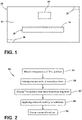
FIG. 1 is a schematic representation of an appliance equipped with a substrate that has a coating, according to one example; and -
FIG. 2 is a flow diagram illustrating a method of forming the coating for the substrate, according to one example. - The present illustrated embodiments reside primarily in combinations of method steps and apparatus components related to a cooking appliance door push button assembly. Accordingly, the apparatus components and method steps have been represented, where appropriate, by conventional symbols in the drawings, showing only those specific details that are pertinent to understanding the embodiments of the present disclosure so as not to obscure the disclosure with details that will be readily apparent to those of ordinary skill in the art having the benefit of the description herein. Further, like numerals in the description and drawings represent like elements.
- For purposes of description herein, the terms "upper," "lower," "right," "left," "rear," "front," "vertical," "horizontal," and derivatives thereof shall relate to the disclosure as oriented in
FIG. 1 . Unless stated otherwise, the term "front" shall refer to the surface of the element closer to an intended viewer, and the term "rear" shall refer to the surface of the element further from the intended viewer. However, it is to be understood that the disclosure may assume various alternative orientations, except where expressly specified to the contrary. It is also to be understood that the specific devices and processes illustrated in the attached drawings, and described in the following specification are simply exemplary embodiments of the inventive concepts defined in the appended claims. Hence, specific dimensions and other physical characteristics relating to the embodiments disclosed herein are not to be considered as limiting, unless the claims expressly state otherwise. - As used herein, the term "and/or," when used in a list of two or more items, means that any one of the listed items can be employed by itself, or any combination of two or more of the listed items, can be employed. For example, if a composition is described as containing components A, B, and/or C, the composition can contain A alone; B alone; C alone; A and B in combination; A and C in combination; B and C in combination; or A, B, and C in combination.
- The terms "including," "comprises," "comprising," or any other variation thereof, are intended to cover a non-exclusive inclusion, such that a process, method, article, or apparatus that comprises a list of elements does not include only those elements but may include other elements not expressly listed or inherent to such process, method, article, or apparatus. An element proceeded by "comprises a ... " does not, without more constraints, preclude the existence of additional identical elements in the process, method, article, or apparatus that comprises the element.
- With respect to
FIG. 1 , asubstrate 20 is provided with acoating 24 on at least one surface thereof. In some examples, thecoating 24 may be provided on an entirety of available external surfaces of thesubstrate 20. Alternatively, thecoating 24 may be provided on less than an entirety of available external surfaces of thesubstrate 20. Thecoating 24 includes a first portion and a second portion. The first portion includes a first liquid silicone rubber, carbon nanotubes, and at least one ferrite-containing component chosen from carbon ferrite and nickel manganese ferrite. Said another way, the first portion can include carbon ferrite and/or nickel manganese ferrite. In various examples, the carbon nanotubes can be present at a concentration of at least about 0.3% by weight of the first portion. For example, the carbon nanotubes can be present at a concentration of about 0.3%, about 0.4%, about 0.5%, about 0.6%, about 0.7%, about 0.8%, about 0.9%, about 1.0%, about 1.1%, about 1.2%, about 1.3%, about 1.4%, about 1.5%, about 1.6%, about 1.7%, about 1.8%, about 1.9%, or about 2.0% by weight of the first portion. When carbon ferrite and nickel manganese ferrite are both present, a combined concentration of the carbon ferrite and the nickel manganese ferrite within the first portion can be in a range of about 60% to about 90% by weight of the first portion. For example, the carbon ferrite can be present at a concentration of about 20%, about 25%, about 30%, about 35%, or about 40% by weight of the first portion, while the nickel manganese ferrite is present at a concentration of about 40%, about 45%, about 50%, about 55%, about 60%, about 65%, or about 70% by weight of the first portion. - Referring again to
FIG. 1 , the second portion includes a second liquid silicone rubber, carbon nanotubes, and at least one ferrite-containing component chosen from carbon ferrite and nickel manganese ferrite. Said another way, the second portion can include carbon ferrite and/or nickel manganese ferrite. In some examples, the carbon nanotubes can be present at a concentration of at least about 0.3% by weight of the second portion. For example, the carbon nanotubes can be present at a concentration of about 0.3%, about 0.4%, about 0.5%, about 0.6%, about 0.7%, about 0.8%, about 0.9%, about 1.0%, about 1.1%, about 1.2%, about 1.3%, about 1.4%, about 1.5%, about 1.6%, about 1.7%, about 1.8%, about 1.9%, or about 2.0% by weight of the second portion. When carbon ferrite and nickel manganese ferrite are both present, a combined concentration of the carbon ferrite and the nickel manganese ferrite within the second portion can be in the range of about 60% to about 90% by weight of the second portion. For example, the carbon ferrite can be present at a concentration of about 20%, about 25%, about 30%, about 35%, or about 40% by weight of the second portion, while the nickel manganese ferrite is present at a concentration of about 40%, about 45%, about 50%, about 55%, about 60%, about 65%, or about 70% by weight of the second portion. In various examples, the carbon ferrite may be used as the sole ferrite component in thecoating 24 or the nickel manganese ferrite may be used as the sole ferrite component in thecoating 24. Accordingly, the carbon ferrite may be present at a concentration of about 60% to about 90% by weight of thecoating 24. Similarly, in alternative examples, the nickel manganese ferrite may be present at a concentration of about 60% to about 90% by weight of thecoating 24. - The
substrate 20 and thecoating 24 are designed for use within a heated environment of anappliance 28. For example, theappliance 28 may be, but is not limited to a microwave oven, an oven, an air fryer, or anyother appliance 28 that provides a heated environment to a cavity 32 defined bywalls 36 of theappliance 28. In various examples, thesubstrate 20 and/or thecoating 24 may be utilized as a heat-producing component on a hot plate, a crisper plate, a heating element, etc. of acooking appliance 28. In a preferred embodiment of the invention, theappliance 28 is a microwave oven and thesubstrate 20 is the surface intended to receive food items to be cooked of a cooking vessel, e.g. a crisper plate. Thecoating 24 is applied onto the surface intended to receive food items to be cooked. Thecrisper plate 20 may be coated with thecoating 24, thereby being provided with Accordingly, the composition of thecoating 24 is formulated to withstand the heated environment within the cavity 32, as well as the heat provided by thesubstrate 20 and/or thecoating 24. In some examples, the formulation of thecoating 24 can be designed to generate heat. For example, components of the coating 24 (e.g., the carbon nanotubes, the carbon ferrite, and/or the nickel manganese ferrite) may be utilized in converting energy of a first type to energy of a second type. - In one example, the first type of energy may be electrical energy and the second type of energy may be thermal energy. In such an example, the electrical energy may be converted into the thermal energy as a result of thermo-resistive properties imparted to the
coating 24 due to the chosen formulation. In another example, the first type of energy may be electro-magnetic energy (e.g., microwave energy) and the second type of energy may be thermal energy. In such an example, the electro-magnetic energy may interact with one or more components of the formulation of the coating 24 (e.g., the carbon ferrite and/or the nickel manganese ferrite) to convert the electro-magnetic energy into the thermal energy. It is contemplated that energy of a third type may be an intermediate step during the transition from the first type of energy to the second type of energy. For example, the third type of energy may be kinetic energy (e.g., vibration). - In examples where the formulation of the
coating 24 is chosen to convert electro-magnetic energy into thermal energy, thecoating 24 may exhibit a Curie temperature. The Curie temperature is the temperature at which a material begins to lose its magnetic properties. Once the Curie temperature is reached, absorption of the electro-magnetic energy (e.g., microwave energy) ceases and further heating can be prevented. Accordingly, the formulation of thecoating 24 can be chosen or designed with a particular operating temperature or a maximum temperature in mind. In various examples, the Curie temperature of thecoating 24 can be at least about 300°C. For example, the Curie temperature can be at least about 300°C, at least about 350°C, at least about 400°C, at least about 450°C, at least about 500°C, and/or combinations or ranges thereof. It is contemplated that the formulation of thecoating 24 may be chosen such that a plurality of Curie temperatures exists for thecoating 24. Regardless of the formulation of thecoating 24, thesubstrate 20 may be made from a thermally conductive and/or an electrically conductive material (e.g., a metallic material). - In various examples, the
appliance 28 may include afan 40, a pump, or a similar device, that can be energized to circulate fluid (e.g., air or water) within the cavity 32 of theappliance 28. By energizing, or turning on, thefan 40, fluid within the cavity 32 can be circulated to provide a more even distribution or diffusion of heat within the heated environment. The pump or similar device could be used in place of thefan 40 based on a particular example of theappliance 28. By providing a more even distribution or diffusion of heat within the heated environment, cooking, cleaning, and/or sanitizing operations that are performed by theappliance 28 can be carried out in a manner that is effective and/or efficient. For example, the more even distribution or diffusion of heat within the heated environment provided to the cavity 32 can result in more even and reproducible cooking, more effective or efficient cleaning of items within the cavity 32, and/or more effective or efficient sanitization of items within the cavity 32. - Referring now to
FIG. 2 , amethod 50 of forming thecoating 24 for thesubstrate 20 is depicted, according to one example. Themethod 50 includesstep 54 of mixing components of the first portion of thecoating 24. More specifically, thestep 54 can include mixing the first liquid silicone rubber, carbon nanotubes, and at least one ferrite-containing component chosen from carbon ferrite and nickel manganese ferrite at a speed of at least about 1650 rpm for a duration of about one minute to form the first portion of thecoating 24. For example, the speed of mixing may be about 1650 rpm, about 1700 rpm, about 1750 rpm, about 1800 rpm, about 1850 rpm, about 1900 rpm, about 1950 rpm, about 2000 rpm, and/or combinations or ranges thereof. In various examples, the carbon nanotubes may be present at a concentration of at least about 0.3% by weight of the first portion. For example, the carbon nanotubes can be present at a concentration of about 0.3%, about 0.4%, about 0.5%, about 0.6%, about 0.7%, about 0.8%, about 0.9%, about 1.0%, about 1.1%, about 1.2%, about 1.3%, about 1.4%, about 1.5%, about 1.6%, about 1.7%, about 1.8%, about 1.9%, or about 2.0% by weight of the first portion. In some examples, as discussed above, when carbon ferrite and nickel manganese ferrite are both present, the combined concentration of the carbon ferrite and the nickel manganese ferrite within the first portion can be in the range of about 60% to about 90% by weight of the first portion. For example, the carbon ferrite can be present at a concentration of about 20%, about 25%, about 30%, about 35%, or about 40% by weight of the first portion, while the nickel manganese ferrite is present at a concentration of about 40%, about 45%, about 50%, about 55%, about 60%, about 65%, or about 70% by weight of the first portion. - Referring again to
FIG. 2 , the method also includesstep 58 of mixing the components of the second portion of thecoating 24. More specifically, thestep 58 can include mixing the second liquid silicone rubber, carbon nanotubes, and at least one ferrite-containing component chosen from carbon ferrite and nickel manganese ferrite at a speed of at least about 1650 rpm for a duration of about one minute to form the second portion of thecoating 24. For example, the speed of mixing may be about 1650 rpm, about 1700 rpm, about 1750 rpm, about 1800 rpm, about 1850 rpm, about 1900 rpm, about 1950 rpm, about 2000 rpm, and/or combinations or ranges thereof. In some examples, the carbon nanotubes may be present at a concentration of at least about 0.3% by weight of the second portion. For example, the carbon nanotubes can be present at a concentration of about 0.3%, about 0.4%, about 0.5%, about 0.6%, about 0.7%, about 0.8%, about 0.9%, about 1.0%, about 1.1%, about 1.2%, about 1.3%, about 1.4%, about 1.5%, about 1.6%, about 1.7%, about 1.8%, about 1.9%, or about 2.0% by weight of the second portion. - Referring further to
FIG. 2 , in some examples, a three-dimensional (3D) bladeless centrifuge speed mixer can be employed in mixing the components of the first portion, mixing the components of the second portion, and/or mixing the first portion and the second portion together. In various examples, as discussed above, when carbon ferrite and nickel manganese ferrite are both present, the combined concentration of the carbon ferrite and the nickel manganese ferrite within the second portion can be in the range of about 60% to about 90% by weight of the second portion. For example, the carbon ferrite can be present at a concentration of about 20%, about 25%, about 30%, about 35%, or about 40% by weight of the second portion, while the nickel manganese ferrite is present at a concentration of about 40%, about 45%, about 50%, about 55%, about 60%, about 65%, or about 70% by weight of the second portion. In various examples, the carbon ferrite may be used as the sole ferrite component in thecoating 24 or the nickel manganese ferrite may be used as the sole ferrite component in thecoating 24. Accordingly, the carbon ferrite may be present at a concentration of about 60% to about 90% by weight of thecoating 24. Similarly, in alternative examples, the nickel manganese ferrite may be present at a concentration of about 60% to about 90% by weight of thecoating 24. - Referring still further to
FIG. 2 , themethod 50 can further includestep 62 of mixing the first portion and the second portion together at a speed of less than about 1650 rpm for a duration of at least about one minute to create an uncured coating. For example, the speed of mixing forstep 62 may be about 1600 rpm, about 1550 rpm, about 1500 rpm, about 1450 rpm, about 1400 rpm, about 1350 rpm, about 1300 rpm, about 1250 rpm, about 1200 rpm, and/or combinations or ranges thereof. Themethod 50 can additionally includestep 66 of applying the uncured coating to thesubstrate 20. Instep 66, the uncured coating may be applied to at least one exterior surface of thesubstrate 20. In various examples, themethod 50 of forming thecoating 24 for thesubstrate 20 may conclude withstep 70 of curing the uncured coating to form thecoating 24 on thesubstrate 20. In some examples, thestep 70 of curing the uncured coating to form thecoating 24 on thesubstrate 20 can include placing thesubstrate 20 that has received the uncured coating into a less-than-atmospheric pressure environment. In such an example, the less-than-atmospheric pressure environment may be held at a temperature of about 70°C. Additionally, in such an example, thesubstrate 20 with the uncured coating applied thereto may remain in the heated less-than-atmospheric pressure environment for a duration of time that is between about 10 minutes and about 40 minutes. For example, the duration of time that thesubstrate 20 with the uncured coating applied thereto may remain in the heated less-than-atmospheric pressure environment may be about 10 minutes, about 15 minutes, about 20 minutes, about 25 minutes, about 30 minutes, about 35 minutes, about 40 minutes, and/or combinations or ranges thereof. - In various examples, the first and second liquid silicone rubbers can be readily mixed with one another and can be rapidly heat-cured into durable elastomers. In some examples, the first portion of the
coating 24 may be used for mixing additives (e.g., active ingredients) while the second portion of thecoating 24 may be used to adjust a viscosity of the formulation of thecoating 24. In various examples, active ingredients to the formulation of thecoating 24 can include the carbon nanotubes, the carbon ferrite, and/or the nickel manganese ferrite. In one specific example, the formulation of thecoating 24 includes the first portion at a concentration of 80% and the second portion at a concentration of 20%. Said another way, in one specific example, the formulation of thecoating 24 can be an 80:20 mixture of the first portion and the second portion, respectively. In one specific example of the formulation of thecoating 24, the carbon ferrite was present at a concentration of 77.5% by weight of thecoating 24, the carbon nanotube were present at a concentration of 2.5% by weight of thecoating 24, and the first and second liquid silicone rubbers were present at a total concentration of 20% by weight of thecoating 24. In another specific example of the formulation of thecoating 24, the nickel manganese ferrite was present at a concentration of 80% by weight of thecoating 24, the carbon nanotubes were present at a concentration of 1.5% by weight of thecoating 24, and the first and second liquid silicone rubbers were present at a total concentration of 18.5% by weight of thecoating 24. - It will be understood by one having ordinary skill in the art that construction of the described disclosure and other components is not limited to any specific material. Other exemplary embodiments of the disclosure disclosed herein may be formed from a wide variety of materials, unless described otherwise herein.
- For purposes of this disclosure, the term "coupled" (in all of its forms, couple, coupling, coupled, etc.) generally means the joining of two components (electrical or mechanical) directly or indirectly to one another. Such joining may be stationary in nature or movable in nature. Such joining may be achieved with the two components (electrical or mechanical) and any additional intermediate members being integrally formed as a single unitary body with one another or with the two components. Such joining may be permanent in nature or may be removable or releasable in nature unless otherwise stated.
- It is also important to note that the construction and arrangement of the elements of the disclosure as shown in the exemplary embodiments is illustrative only. Although only a few embodiments of the present innovations have been described in detail in this disclosure, those skilled in the art who review this disclosure will readily appreciate that many modifications are possible (e.g., variations in sizes, dimensions, structures, shapes and proportions of the various elements, values of parameters, mounting arrangements, use of materials, colors, orientations, etc.) without materially departing from the novel teachings and advantages of the subject matter recited. For example, elements shown as integrally formed may be constructed of multiple parts or elements shown as multiple parts may be integrally formed, the operation of the interfaces may be reversed or otherwise varied, the length or width of the structures and/or members or connector or other elements of the system may be varied, the nature or number of adjustment positions provided between the elements may be varied. It should be noted that the elements and/or assemblies of the system may be constructed from any of a wide variety of materials that provide sufficient strength or durability, in any of a wide variety of colors, textures, and combinations. Accordingly, all such modifications are intended to be included within the scope of the present innovations. Other substitutions, modifications, changes, and omissions may be made in the design, operating conditions, and arrangement of the desired and other exemplary embodiments without departing from the spirit of the present innovations.
Claims (15)
- A coating (24) for a substrate (20), comprising:a first portion, wherein the first portion comprises:a first liquid silicone rubber;carbon nanotubes at a concentration of at least about 0.5% by weight of the first portion; andat least one ferrite-containing component chosen from carbon ferrite and nickel manganese ferrite; anda second portion, wherein the second portion comprises:a second liquid silicone rubber;carbon nanotubes at a concentration of at least about 0.5% by weight of the second portion; andat least one ferrite-containing component chosen from carbon ferrite and nickel manganese ferrite.
- The coating (24) for a substrate (20) of claim 1, wherein the concentration of carbon nanotubes within the first portion is about 1.0% by weight of the first portion.
- The coating (24) for a substrate (20) of claim 2, wherein the concentration of carbon nanotubes within the second portion is about 1.0% by weight of the second portion.
- The coating (24) for a substrate (20) of claim 1, wherein the at least one ferrite-containing component within the first portion is carbon ferrite, wherein the at least one ferrite-containing component within the second portion is carbon ferrite, and wherein the carbon ferrite is present at a concentration of about 60% to about 90% by weight of the coating (24).
- The coating (24) for a substrate (20) of claim 4, wherein the carbon ferrite is present within the first portion at a concentration of about 20% to about 40% by weight of the first portion, and wherein the nickel manganese ferrite is present within the first portion at a concentration of about 40% to about 70% by weight of the first portion.
- The coating (24) for a substrate (20) of claim 1, wherein the at least one ferrite-containing component within the first portion is nickel manganese ferrite, wherein the at least one ferrite-containing component within the second portion is nickel manganese ferrite, and wherein the nickel manganese ferrite is present at a concentration of about 60% to about 90% by weight of the coating (24).
- The coating (24) for a substrate (20) of claim 6, wherein the carbon ferrite is present within the second portion at a concentration of about 20% to about 40% by weight of the second portion, and wherein the nickel manganese ferrite is present within the second portion at a concentration of about 40% to about 70% by weight of the second portion.
- The coating (24) for a substrate (20) of claim 1, wherein the at least one ferrite-containing component within the first portion comprises carbon ferrite and nickel manganese ferrite, and wherein a combined concentration of the carbon ferrite and the nickel manganese ferrite within the first portion is in a range of about 60% to about 90% by weight of the first portion.
- The coating (24) for a substrate (20) of claim 4, wherein the at least one ferrite-containing component within the second portion comprises carbon ferrite and nickel manganese ferrite, and wherein a combined concentration of the carbon ferrite and the nickel manganese ferrite within the second portion is in a range of about 60% to about 90% by weight of the second portion.
- The coating (24) for a substrate (20) of claim 9, wherein the coating exhibits a Curie temperature of at least about 300°C.
- The coating (24) for a substrate (20) of claim 1, wherein the coating exhibits a Curie temperature of at least about 300°C.
- A substrate (20) comprising the coating (24) of any one of the preceding claims.
- The substrate (20) of claim 12, wherein the coating (24) covers an entirety of a surface area of the substrate (20).
- A cooking vessel for cooking appliance, wherein a surface of the cooking vessel intended to receive food items to be cooked is the substrate of claim 12.
- The cooking vessel of claim 14, wherein the cooking vessel is a crisper plate and the cooking appliance is a microwave oven.
Applications Claiming Priority (2)
| Application Number | Priority Date | Filing Date | Title |
|---|---|---|---|
| US202163208765P | 2021-06-09 | 2021-06-09 | |
| US17/748,410 US20220396714A1 (en) | 2021-06-09 | 2022-05-19 | Coating for a substrate |
Publications (1)
| Publication Number | Publication Date |
|---|---|
| EP4101943A1 true EP4101943A1 (en) | 2022-12-14 |
Family
ID=82458642
Family Applications (1)
| Application Number | Title | Priority Date | Filing Date |
|---|---|---|---|
| EP22177061.3A Withdrawn EP4101943A1 (en) | 2021-06-09 | 2022-06-02 | Coating for a substrate |
Country Status (3)
| Country | Link |
|---|---|
| US (1) | US20220396714A1 (en) |
| EP (1) | EP4101943A1 (en) |
| CN (1) | CN115448645A (en) |
Citations (4)
| Publication number | Priority date | Publication date | Assignee | Title |
|---|---|---|---|---|
| JP2000302970A (en) * | 1999-04-19 | 2000-10-31 | Suzuki Sogyo Co Ltd | Thermally conductive silicone rubber composition, its molding product and it applied product |
| US20120067871A1 (en) * | 2010-09-20 | 2012-03-22 | David William Sherrer | Device Package and Methods for the Fabrication Thereof |
| CN111642969A (en) * | 2020-06-09 | 2020-09-11 | 中山市屹立塑胶制品有限公司 | Multifunctional cooking container for microwave oven and preparation method thereof |
| EP4025015A1 (en) * | 2020-12-30 | 2022-07-06 | Whirlpool Corporation | Phase-gate hybrid coating crisp plate |
Family Cites Families (8)
| Publication number | Priority date | Publication date | Assignee | Title |
|---|---|---|---|---|
| AU1436001A (en) * | 1999-10-20 | 2001-04-30 | Loctite Corporation | Microwave curable compositions |
| US7625633B2 (en) * | 2003-03-25 | 2009-12-01 | Shin-Etsu Polymer., Ltd. | Electromagnetic noise suppressor, article with electromagnetic noise suppressing function, and their manufacturing methods |
| JP2013085915A (en) * | 2011-10-24 | 2013-05-13 | Panasonic Corp | Heating cooker |
| US9337152B2 (en) * | 2013-03-15 | 2016-05-10 | Nuvotronics, Inc | Formulation for packaging an electronic device and assemblies made therefrom |
| IT201700109605A1 (en) * | 2017-09-29 | 2019-03-29 | Verniciature Bresciane S R L | COOKTOP WITH HEATING COATING |
| US11234298B2 (en) * | 2018-11-15 | 2022-01-25 | Whirlpool Corporation | Hybrid nanoreinforced liner for microwave oven |
| CN109348698A (en) * | 2018-12-12 | 2019-02-15 | 横店集团东磁股份有限公司 | A kind of ferrite-carbon nanotube composite wave absorbing material and preparation method thereof |
| WO2021094836A1 (en) * | 2019-11-14 | 2021-05-20 | Ministry Of Electronics & Information Technology (Meity) | Electromagnetic interference shielding composition, article and methods thereof |
-
2022
- 2022-05-19 US US17/748,410 patent/US20220396714A1/en active Pending
- 2022-06-02 EP EP22177061.3A patent/EP4101943A1/en not_active Withdrawn
- 2022-06-08 CN CN202210646648.0A patent/CN115448645A/en active Pending
Patent Citations (4)
| Publication number | Priority date | Publication date | Assignee | Title |
|---|---|---|---|---|
| JP2000302970A (en) * | 1999-04-19 | 2000-10-31 | Suzuki Sogyo Co Ltd | Thermally conductive silicone rubber composition, its molding product and it applied product |
| US20120067871A1 (en) * | 2010-09-20 | 2012-03-22 | David William Sherrer | Device Package and Methods for the Fabrication Thereof |
| CN111642969A (en) * | 2020-06-09 | 2020-09-11 | 中山市屹立塑胶制品有限公司 | Multifunctional cooking container for microwave oven and preparation method thereof |
| EP4025015A1 (en) * | 2020-12-30 | 2022-07-06 | Whirlpool Corporation | Phase-gate hybrid coating crisp plate |
Also Published As
| Publication number | Publication date |
|---|---|
| US20220396714A1 (en) | 2022-12-15 |
| CN115448645A (en) | 2022-12-09 |
Similar Documents
| Publication | Publication Date | Title |
|---|---|---|
| US9538776B2 (en) | Pressurized oven assembly | |
| EP0333423A1 (en) | Heat generating container for microwave oven | |
| US20160150602A1 (en) | Microwave heating element | |
| KR20050029277A (en) | Ovenware for microwave oven | |
| EP3298861B1 (en) | Apparatus for providing customizable heat zones in an oven | |
| US20240206674A1 (en) | Artificial Gravity Heating Device | |
| US20220396714A1 (en) | Coating for a substrate | |
| US20040000545A1 (en) | Microwave oven, and guide roller, cooking tray and dish for use in microwave oven | |
| EP3424273B1 (en) | Heat modulating food packaging material | |
| CN109556148A (en) | Micro-wave oven and its control method | |
| KR100876352B1 (en) | Microwave ceramic container and manufacturing method thereof | |
| AU2017206189A1 (en) | Microwaveable container | |
| KR100470316B1 (en) | Ceramic heating element and method of the same | |
| JP2008281302A (en) | Cooking equipment | |
| EP3476183B1 (en) | Multi-feed microwave oven with improved crisp function | |
| EP4149208B1 (en) | Crisp plate for microwave ovens | |
| JP5453799B2 (en) | Microwave cookware and microwave oven | |
| JP2004055507A (en) | Cooking utensil with agitating function | |
| IE20070541A1 (en) | Stirring device | |
| JP2010078207A (en) | High frequency heating element and cooking appliance for high frequency heating apparatus using the same | |
| CN110652227A (en) | Baking appliance and control method thereof | |
| JP4804580B1 (en) | Method for surface modification of sintered carbon | |
| CN101857739A (en) | Exothermic paint capable of absorbing microwaves | |
| EP4570147A1 (en) | Food preparation utensil and food preparation assembly comprising the same | |
| WO2025113947A1 (en) | Food preparation utensil and food preparation assembly comprising the same |
Legal Events
| Date | Code | Title | Description |
|---|---|---|---|
| PUAI | Public reference made under article 153(3) epc to a published international application that has entered the european phase |
Free format text: ORIGINAL CODE: 0009012 |
|
| STAA | Information on the status of an ep patent application or granted ep patent |
Free format text: STATUS: THE APPLICATION HAS BEEN PUBLISHED |
|
| AK | Designated contracting states |
Kind code of ref document: A1 Designated state(s): AL AT BE BG CH CY CZ DE DK EE ES FI FR GB GR HR HU IE IS IT LI LT LU LV MC MK MT NL NO PL PT RO RS SE SI SK SM TR |
|
| STAA | Information on the status of an ep patent application or granted ep patent |
Free format text: STATUS: THE APPLICATION IS DEEMED TO BE WITHDRAWN |
|
| 18D | Application deemed to be withdrawn |
Effective date: 20230615 |