EP4101704A1 - Unauthorized connection detecting device - Google Patents
Unauthorized connection detecting device Download PDFInfo
- Publication number
- EP4101704A1 EP4101704A1 EP22177783.2A EP22177783A EP4101704A1 EP 4101704 A1 EP4101704 A1 EP 4101704A1 EP 22177783 A EP22177783 A EP 22177783A EP 4101704 A1 EP4101704 A1 EP 4101704A1
- Authority
- EP
- European Patent Office
- Prior art keywords
- connector
- unit
- unauthorized
- connectors
- connection detecting
- Prior art date
- Legal status (The legal status is an assumption and is not a legal conclusion. Google has not performed a legal analysis and makes no representation as to the accuracy of the status listed.)
- Granted
Links
Images






Classifications
-
- B—PERFORMING OPERATIONS; TRANSPORTING
- B60—VEHICLES IN GENERAL
- B60R—VEHICLES, VEHICLE FITTINGS, OR VEHICLE PARTS, NOT OTHERWISE PROVIDED FOR
- B60R16/00—Electric or fluid circuits specially adapted for vehicles and not otherwise provided for; Arrangement of elements of electric or fluid circuits specially adapted for vehicles and not otherwise provided for
- B60R16/02—Electric or fluid circuits specially adapted for vehicles and not otherwise provided for; Arrangement of elements of electric or fluid circuits specially adapted for vehicles and not otherwise provided for electric constitutive elements
- B60R16/03—Electric or fluid circuits specially adapted for vehicles and not otherwise provided for; Arrangement of elements of electric or fluid circuits specially adapted for vehicles and not otherwise provided for electric constitutive elements for supply of electrical power to vehicle subsystems or for
-
- B—PERFORMING OPERATIONS; TRANSPORTING
- B60—VEHICLES IN GENERAL
- B60R—VEHICLES, VEHICLE FITTINGS, OR VEHICLE PARTS, NOT OTHERWISE PROVIDED FOR
- B60R16/00—Electric or fluid circuits specially adapted for vehicles and not otherwise provided for; Arrangement of elements of electric or fluid circuits specially adapted for vehicles and not otherwise provided for
- B60R16/02—Electric or fluid circuits specially adapted for vehicles and not otherwise provided for; Arrangement of elements of electric or fluid circuits specially adapted for vehicles and not otherwise provided for electric constitutive elements
- B60R16/023—Electric or fluid circuits specially adapted for vehicles and not otherwise provided for; Arrangement of elements of electric or fluid circuits specially adapted for vehicles and not otherwise provided for electric constitutive elements for transmission of signals between vehicle parts or subsystems
-
- H—ELECTRICITY
- H04—ELECTRIC COMMUNICATION TECHNIQUE
- H04L—TRANSMISSION OF DIGITAL INFORMATION, e.g. TELEGRAPHIC COMMUNICATION
- H04L9/00—Cryptographic mechanisms or cryptographic arrangements for secret or secure communications; Network security protocols
- H04L9/38—Encryption being effected by mechanical apparatus, e.g. rotating cams, switches, keytape punchers
-
- B—PERFORMING OPERATIONS; TRANSPORTING
- B60—VEHICLES IN GENERAL
- B60R—VEHICLES, VEHICLE FITTINGS, OR VEHICLE PARTS, NOT OTHERWISE PROVIDED FOR
- B60R16/00—Electric or fluid circuits specially adapted for vehicles and not otherwise provided for; Arrangement of elements of electric or fluid circuits specially adapted for vehicles and not otherwise provided for
- B60R16/02—Electric or fluid circuits specially adapted for vehicles and not otherwise provided for; Arrangement of elements of electric or fluid circuits specially adapted for vehicles and not otherwise provided for electric constitutive elements
- B60R16/023—Electric or fluid circuits specially adapted for vehicles and not otherwise provided for; Arrangement of elements of electric or fluid circuits specially adapted for vehicles and not otherwise provided for electric constitutive elements for transmission of signals between vehicle parts or subsystems
- B60R16/0231—Circuits relating to the driving or the functioning of the vehicle
- B60R16/0232—Circuits relating to the driving or the functioning of the vehicle for measuring vehicle parameters and indicating critical, abnormal or dangerous conditions
-
- B—PERFORMING OPERATIONS; TRANSPORTING
- B60—VEHICLES IN GENERAL
- B60R—VEHICLES, VEHICLE FITTINGS, OR VEHICLE PARTS, NOT OTHERWISE PROVIDED FOR
- B60R16/00—Electric or fluid circuits specially adapted for vehicles and not otherwise provided for; Arrangement of elements of electric or fluid circuits specially adapted for vehicles and not otherwise provided for
- B60R16/02—Electric or fluid circuits specially adapted for vehicles and not otherwise provided for; Arrangement of elements of electric or fluid circuits specially adapted for vehicles and not otherwise provided for electric constitutive elements
- B60R16/023—Electric or fluid circuits specially adapted for vehicles and not otherwise provided for; Arrangement of elements of electric or fluid circuits specially adapted for vehicles and not otherwise provided for electric constitutive elements for transmission of signals between vehicle parts or subsystems
- B60R16/0239—Electronic boxes
-
- B—PERFORMING OPERATIONS; TRANSPORTING
- B60—VEHICLES IN GENERAL
- B60R—VEHICLES, VEHICLE FITTINGS, OR VEHICLE PARTS, NOT OTHERWISE PROVIDED FOR
- B60R25/00—Fittings or systems for preventing or indicating unauthorised use or theft of vehicles
- B60R25/40—Features of the power supply for the anti-theft system, e.g. anti-theft batteries, back-up power supply or means to save battery power
- B60R25/403—Power supply in the vehicle
-
- G—PHYSICS
- G06—COMPUTING OR CALCULATING; COUNTING
- G06F—ELECTRIC DIGITAL DATA PROCESSING
- G06F21/00—Security arrangements for protecting computers, components thereof, programs or data against unauthorised activity
- G06F21/50—Monitoring users, programs or devices to maintain the integrity of platforms, e.g. of processors, firmware or operating systems
- G06F21/55—Detecting local intrusion or implementing counter-measures
- G06F21/552—Detecting local intrusion or implementing counter-measures involving long-term monitoring or reporting
-
- G—PHYSICS
- G06—COMPUTING OR CALCULATING; COUNTING
- G06F—ELECTRIC DIGITAL DATA PROCESSING
- G06F21/00—Security arrangements for protecting computers, components thereof, programs or data against unauthorised activity
- G06F21/70—Protecting specific internal or peripheral components, in which the protection of a component leads to protection of the entire computer
- G06F21/82—Protecting input, output or interconnection devices
- G06F21/85—Protecting input, output or interconnection devices interconnection devices, e.g. bus-connected or in-line devices
-
- H—ELECTRICITY
- H04—ELECTRIC COMMUNICATION TECHNIQUE
- H04L—TRANSMISSION OF DIGITAL INFORMATION, e.g. TELEGRAPHIC COMMUNICATION
- H04L9/00—Cryptographic mechanisms or cryptographic arrangements for secret or secure communications; Network security protocols
- H04L9/32—Cryptographic mechanisms or cryptographic arrangements for secret or secure communications; Network security protocols including means for verifying the identity or authority of a user of the system or for message authentication, e.g. authorization, entity authentication, data integrity or data verification, non-repudiation, key authentication or verification of credentials
-
- G—PHYSICS
- G06—COMPUTING OR CALCULATING; COUNTING
- G06F—ELECTRIC DIGITAL DATA PROCESSING
- G06F2221/00—Indexing scheme relating to security arrangements for protecting computers, components thereof, programs or data against unauthorised activity
- G06F2221/03—Indexing scheme relating to G06F21/50, monitoring users, programs or devices to maintain the integrity of platforms
- G06F2221/034—Test or assess a computer or a system
-
- H—ELECTRICITY
- H01—ELECTRIC ELEMENTS
- H01R—ELECTRICALLY-CONDUCTIVE CONNECTIONS; STRUCTURAL ASSOCIATIONS OF A PLURALITY OF MUTUALLY-INSULATED ELECTRICAL CONNECTING ELEMENTS; COUPLING DEVICES; CURRENT COLLECTORS
- H01R13/00—Details of coupling devices of the kinds covered by groups H01R12/70 or H01R24/00 - H01R33/00
- H01R13/46—Bases; Cases
- H01R13/465—Identification means, e.g. labels, tags, markings
-
- H—ELECTRICITY
- H01—ELECTRIC ELEMENTS
- H01R—ELECTRICALLY-CONDUCTIVE CONNECTIONS; STRUCTURAL ASSOCIATIONS OF A PLURALITY OF MUTUALLY-INSULATED ELECTRICAL CONNECTING ELEMENTS; COUPLING DEVICES; CURRENT COLLECTORS
- H01R13/00—Details of coupling devices of the kinds covered by groups H01R12/70 or H01R24/00 - H01R33/00
- H01R13/64—Means for preventing incorrect coupling
-
- H—ELECTRICITY
- H01—ELECTRIC ELEMENTS
- H01R—ELECTRICALLY-CONDUCTIVE CONNECTIONS; STRUCTURAL ASSOCIATIONS OF A PLURALITY OF MUTUALLY-INSULATED ELECTRICAL CONNECTING ELEMENTS; COUPLING DEVICES; CURRENT COLLECTORS
- H01R13/00—Details of coupling devices of the kinds covered by groups H01R12/70 or H01R24/00 - H01R33/00
- H01R13/66—Structural association with built-in electrical component
- H01R13/665—Structural association with built-in electrical component with built-in electronic circuit
-
- H—ELECTRICITY
- H01—ELECTRIC ELEMENTS
- H01R—ELECTRICALLY-CONDUCTIVE CONNECTIONS; STRUCTURAL ASSOCIATIONS OF A PLURALITY OF MUTUALLY-INSULATED ELECTRICAL CONNECTING ELEMENTS; COUPLING DEVICES; CURRENT COLLECTORS
- H01R13/00—Details of coupling devices of the kinds covered by groups H01R12/70 or H01R24/00 - H01R33/00
- H01R13/66—Structural association with built-in electrical component
- H01R13/70—Structural association with built-in electrical component with built-in switch
-
- H—ELECTRICITY
- H01—ELECTRIC ELEMENTS
- H01R—ELECTRICALLY-CONDUCTIVE CONNECTIONS; STRUCTURAL ASSOCIATIONS OF A PLURALITY OF MUTUALLY-INSULATED ELECTRICAL CONNECTING ELEMENTS; COUPLING DEVICES; CURRENT COLLECTORS
- H01R13/00—Details of coupling devices of the kinds covered by groups H01R12/70 or H01R24/00 - H01R33/00
- H01R13/66—Structural association with built-in electrical component
- H01R13/70—Structural association with built-in electrical component with built-in switch
- H01R13/703—Structural association with built-in electrical component with built-in switch operated by engagement or disengagement of coupling parts, e.g. dual-continuity coupling part
- H01R13/7039—Structural association with built-in electrical component with built-in switch operated by engagement or disengagement of coupling parts, e.g. dual-continuity coupling part the coupling part with coding means activating the switch to establish different circuits
-
- H—ELECTRICITY
- H01—ELECTRIC ELEMENTS
- H01R—ELECTRICALLY-CONDUCTIVE CONNECTIONS; STRUCTURAL ASSOCIATIONS OF A PLURALITY OF MUTUALLY-INSULATED ELECTRICAL CONNECTING ELEMENTS; COUPLING DEVICES; CURRENT COLLECTORS
- H01R2107/00—Four or more poles
-
- H—ELECTRICITY
- H01—ELECTRIC ELEMENTS
- H01R—ELECTRICALLY-CONDUCTIVE CONNECTIONS; STRUCTURAL ASSOCIATIONS OF A PLURALITY OF MUTUALLY-INSULATED ELECTRICAL CONNECTING ELEMENTS; COUPLING DEVICES; CURRENT COLLECTORS
- H01R2201/00—Connectors or connections adapted for particular applications
- H01R2201/26—Connectors or connections adapted for particular applications for vehicles
Definitions
- the presently disclosed subject matter relates to an unauthorized connection detecting device configured to detect an unauthorized device connection on a vehicle.
- a user of a vehicle, a vehicle dealer, or the like may retrofit various optional devices prepared in advance to a vehicle, or may replace various devices according to preference of the user. Therefore, wire harnesses and various electronic control units (ECUs) are often provided with connectors for connecting the retrofit devices in advance, so that the user, the vehicle dealer, or the like can retrofit various devices to the vehicle.
- ECUs electronice control units
- an unauthorized device may be connected to the connector on the vehicle side.
- Such an unauthorized device may cause a malfunction in operation of the vehicle, increase a risk of vehicle theft, or lead to leakage of various information existing on the vehicle side. Therefore, it is necessary to detect the unauthorized connected device on the vehicle side.
- An unauthorized connection detecting method and an unauthorized connection detecting system in the related art appropriately determine presence or absence of tool connection while sharing a communication line for determining the presence or absence of the tool connection with a normal communication line (see, for example, JP2014-143631A ).
- a monitor system that performs differential communication between a window electronic control unit and a monitor tool via a pair of communication lines includes a first step of applying a predetermined voltage to at least one of the pair of communication lines when the window electronic control unit and the legitimate monitor tool are connected to each other via the pair of communication lines, a second step of detecting a voltage generated in at least one of the pair of communication lines and a third step of determining whether or not the legitimate monitor tool is connected to the window electronic control unit via the pair of communication lines based on the voltage generated in at least one of the pair of communication lines detected in the second step.
- the connector for electrically connecting a plurality of members is formed with a built-in tag chip.
- the tag chip is configured to include a storage unit that stores information and an antenna that transmits information wirelessly, so that information can be exchanged with an outside regardless of electrical connection by the connector.
- a range of the wireless information transmission is limited to a range of approximately several mm to prevent information leakage.
- the former related art cannot be used when connecting a device that does not include a communication line to the connector on the vehicle side since it is indispensable to use a communication line to detect the unauthorized device connection.
- the tag chip using a radio frequency identifier is used, and thus an RFID reader that reads information from the tag chip of the connector is required, and a configuration of the ECU on the vehicle side is complicated and a cost goes up.
- RFID radio frequency identifier
- Illustrative aspects of the presently disclosed subject matter provide an unauthorized connection detecting device capable of detecting unauthorized device connection at a low cost when a device that does not include a communication line is connected to an ECU or the like on a vehicle side.
- an unauthorized connection detecting device configured to detect an unauthorized device connection at a connection part at which an electronic control unit mounted on a vehicle and an input and output unit are connected to each other.
- the unauthorized connection detecting device includes a pair of connectors having one connector mounted on the electronic control unit and another connector mounted on the input and output unit, the pair of connectors being configured to be attached to each other, a protrusion formed on the another connector or a conductor pattern formed on the another connector, a switch unit arranged on the one connector and configured to, when the pair of connectors are attached to each other, detect the protrusion or a conductor connection detecting unit arranged on the one connector and configured to be electrically connected to the conductor pattern, and an unauthorized connection identification unit configured to detect an unauthorized connection based on a state detected by the switch unit or the conductor connection detecting unit.
- the one connector may be a first connector and the another connector is a second connector.
- the second connector may have the protrusion.
- Fig. 1 is an electric circuit diagram showing a configuration example of an unauthorized connection detecting device 100 according to the embodiment of the presently disclosed subject matter.
- the unauthorized connection detecting device 100 shown in Fig. 1 is mounted on a vehicle and has a function for preventing some unauthorized unit from being connected to a legitimate in-vehicle unit.
- a zone ECU 10 is a legitimate unit prepared for managing a predetermined zone on the vehicle, and is equipped with a microcomputer (CPU) 11 and a communication function as any ECUs generally have.
- the zone ECU 10 has a function for supplying power of the vehicle side to devices in a managed zone and a function for inputting and outputting a predetermined signal. Zones may be assigned by divisions of various areas in a space of the vehicle, or may be assigned by classifications of functions.
- An input and output interface unit 20 is a legitimate unit prepared in advance, and is an in-vehicle device having a function of inputting or outputting signals to or from the zone ECU 10.
- the zone ECU 10 since the input and output interface unit 20 is not equipped with a computer or a communication function, the zone ECU 10 cannot acquire a state on the input and output interface unit 20 side via a communication function. Therefore, the zone ECU 10 of the present embodiment detects that some unauthorized unit, instead of the input and output interface unit 20, is connected to the zone ECU 10 at a unit connection portion 30 without using any communication function.
- the zone ECU 10 and the input and output interface unit 20 are physically and electrically connected via the unit connection portion 30.
- the unit connection portion 30 includes a connector 31 mounted on the zone ECU 10 side and a connector 32 mounted on the input and output interface unit 20 side.
- the connector 31 is a male type and the connector 32 is a female type, and the two connectors can be fitted to and combined to or separated from each other by insertion and removal operations to both.
- the zone ECU 10 includes one or more control lines 15.
- the control line 15 is used for outputting a predetermined control signal from a microcomputer 11 to the input and output interface unit 20 side and inputting an input signal from the input and output interface unit 20 side to the microcomputer 11.
- the unit connection portion 30 has a power line and ground wire connection function in addition to a connection function of the control line 15.
- a power line of the connector 31 is connected to a power line 12 via a power control switch 16.
- a ground wire of the connector 31 is connected to a ground 13 in the zone ECU 10.
- a switch unit 14 is connected to the ground 13 of the zone ECU 10.
- the switch unit 14 includes a plurality of independent electric contacts incorporated inside the connector 31, which will be described later.
- a plurality of input ports of the microcomputer 11 are connected to the switch unit 14.
- the microcomputer 11 uses a state of the electric contacts of the switch unit 14 to identify whether the mating input and output interface unit 20 or the like is a legitimate unit.
- the connector 32 on the input and output interface unit 20 side includes terminals of a power line 21, a ground 22, and a control line 23.
- the power control switch 16 is a switch that can be turned on and off by the microcomputer 11, and is used for switching on and off for a power supplied from the zone ECU 10 to the input and output interface unit 20 side.
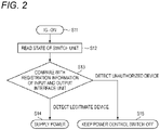
- Fig. 2 is a flowchart showing a main operation example of the zone ECU 10. Control in Fig. 2 is performed by the microcomputer 11 in the zone ECU 10. Operations in Fig. 2 will be described below.
- the microcomputer 11 executes Step S11 of the operations shown in Fig. 2 .
- the microcomputer 11 reads an on or off state of each contact of the switch unit 14 in S12.
- the zone ECU 10 holds in advance information unique to the input and output interface unit 20 or the like that may be connected to the zone ECU 10 in an internal non-volatile memory as predetermined registration information.
- the microcomputer 11 compares the registration information of the input and output interface unit 20 held by the non-volatile memory with the on or off state of the switch unit 14 read in S12.
- the microcomputer 11 identifies the mating unit as a legitimate device and proceeds from S13 to S14. Then, the power control switch 16 is switched on to supply power to the input and output interface unit 20 (S14).
- the microcomputer 11 identifies the mating unit as an unauthorized device and proceeds from S13 to S15. Then, the power control switch 16 is kept to be off. Therefore, in this case, no power is supplied to the mating unit connected to the connector 31 (S15).
- the latest information is added or updated and registered in the zone ECU 10 as needed, using, for example, a vehicle diagnostic tester installed at a vehicle dealer, or the Over The Air (OTA) technique.
- OTA Over The Air
- Fig. 3 is a perspective view showing external appearance of the connector 31 on a male side.
- Fig. 4 is a front view showing the connector 31 on the male side.
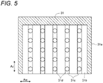
- Fig. 5 is a cross-sectional diagram of a cross section taken along a line A-A in Fig. 4 .
- a terminal 31e is omitted in order to make it easier to see a characteristic portion.
- a connector housing 31a of the connector 31 is formed with an opening 31b for inserting the mating connector 32.
- ten pin-shaped terminals 31e are arranged in the opening 31b.
- each groove 31c On a bottom inner wall of the connector housing 31a, five rows of grooves 31c elongated from the opening 31b and extending toward an insertion and extraction direction (a moving direction of the connectors when they are being attached to each other) Az are formed in parallel with each other.
- a plurality of tact switches 31d are provided in each groove 31c.
- a button capable of moving in a height direction Ay is formed on a top portion of each tact switch 31d.
- An internal electric contact of each tact switch 31d is turned off in a released state, and the electric contact is turned on only when the button is pressed.
- Each button is arranged inside the groove 31c, and a top portion thereof is formed in a curved surface shape so as not to hinder movement of a mating protrusion.
- a plurality of electric wires for connecting the electric contacts in each terminal 31e and each tact switch 31d are arranged on a back side of the connector 31. These electric wires are connected to an electric circuit in the zone ECU 10 shown in Fig. 1 .
- the grooves 31c are formed at predetermined positions, for example, at a predetermined interval from each other.
- the plurality of tact switches 31d are arranged at predetermined positions in the groove 31c, for example, at a predetermined interval from each other.
- the plurality of tact switches 31d form the switch unit 14 in Fig. 1 .
- Fig. 6 is a front view showing the connector 32 on a female side.
- Fig. 7 is a side view showing the connector 32 on the female side.
- Outer shape and size of a connector housing 32a of the connector 32 shown in Figs. 6 and 7 are formed so as to substantially match the opening 31b of the connector 31 shown in Figs. 3 to 5 . Therefore, the connector housing 32a of the connector 32 can be inserted and fitted into the opening 31b of the connector 31.
- the connector housing 32a includes 10 terminals 32d inside.
- Each terminal 32d includes a recess that can accept the pin-shaped terminal 31e on the male side, and is arranged at a position facing each terminal 31e on the male side.
- an electric wire 32e is connected to each terminal 32d in the connector housing 32a. These electric wires 32e are connected to the electric circuit in the input and output interface unit 20 shown in Fig. 1 .
- a plurality of downward protrusions 32c are formed on a bottom surface 32b of the connector housing 32a. These protrusions 32c are arranged at positions matching positions of the grooves 31c and arrangement positions of the tact switches 31d of the connector 31 on the male side. That is, with the connectors 31 and 32 fitted to each other, each protrusion 32c is arranged so as to press the button of any one or more tact switches 31d.
- the connector housings 31a and 32a move relative to each other in the insertion and extraction direction Az, since each protrusion 32c passes through the groove 31c, movement of the protrusions 32c is not interfered.
- a total number of the plurality of protrusions 32c actually provided in the connector housing 32a, a position where each protrusion 32c is arranged, and a length of each protrusion 32c are appropriately determined according to design specifications of the input and output interface unit 20. For example, by setting the total number and arrangement positions of the protrusions 32c to a predetermined state for each type of the input and output interface unit 20, the type of the input and output interface unit 20 can be expressed by differences in arrangement states of the protrusions 32c.
- the microcomputer 11 can detect the arrangement states of the protrusions 32c in the connector 32 on the input and output interface unit 20 side.
- the arrangement states of the protrusions 32c are determined in advance, and thus are held in advance on the zone ECU 10 as the registration information. Therefore, by comparing the information read by the microcomputer 11 in S12 with the registration information in S13, it is possible to identify whether or not the input and output interface unit 20 actually connected is an unauthorized unit, and it is also possible to identify a type of the legitimate unit.
- a connector 31A shown in Fig. 8 and a connector 32A shown in Figs. 9 to 11 can be adopted instead of the connectors 31 and 32.
- the configurations and overall operation of the unauthorized connection detecting device 100 other than the connectors 31A and 32A are the same as those in the above-described embodiment.
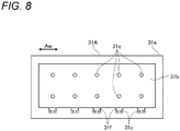
- Fig. 8 is a front view showing the connector 31A on a male side in the modified example.
- the connector 31A shown in Fig. 8 includes the connector housing 31a, the opening 31b, the grooves 31c, and the terminals 31e, as in the case of the connector 31.
- a plurality of switch terminals 31f are arranged in place of the tact switches 31d described above in the grooves 31c of the connector 31A.
- Each switch terminal 31f is a conductive terminal capable of forming an electric contact by facing and contacting a conductor pattern 32f described later.
- each switch terminal 31f is configured by using an elastic metal such as a spring. Therefore, each switch terminal 31f is deformable, and a position of a top portion of the switch terminal 31f can be displaced in the height direction Ay.
- the switch terminals 31f are arranged so as not to hinder the relative movement of the connector housings 31a and 32a in the insertion and extraction direction Az. That is, the top portion of the switch terminal 31f is shaped so as not to protrude significantly from the groove 31c.
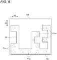
- Fig. 9 is a bottom view showing the connector 32A on a female side in the modified example.
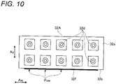
- Fig. 10 is a front view showing the connector 32A on the female side in the modified example.
- Fig. 11 is a side view showing the connector 32A on the female side in the modified example.
- the connector 32A shown in Figs. 9 to 11 includes the connector housing 32a, the bottom surface 32b, and the terminals 32d, as in the case of the connector 32.
- a planar conductor pattern 32f as shown in Fig. 9 is attached to a part of the bottom surface 32b of the connector housing 32a.
- the conductor pattern 32f is made of a thin metal such as a copper foil, and a surface thereof contacts each switch terminal 31f on the opposing connector 31A side to form an electric contact.
- the electric contact is formed at each of a plurality of contact portions Psw shown in Fig. 9 . That is, since each switch terminal 31f on the connector 31A side exists at a position facing each contact portion Psw in Fig. 9 , at the position of each contact portion Psw on the connector 32A, the top portion of the switch terminal 31f and a surface of the conductor pattern 32f are in contact with each other to form an electric contact.
- the plurality of electric contacts formed by each switch terminal 31f and the conductor pattern 32f can be used as they are as the switch unit 14 in Fig. 1 .
- the conductor pattern 32f is connected to the ground 22, when each electric contact formed by the switch terminal 31f and the conductor pattern 32f is closed, a potential of one input port of the microcomputer 11 can be lowered to a potential of the ground 13.
- the unauthorized connection detecting device 100 shown in Fig. 1 even if the input and output interface unit 20 side does not include a CPU or a communication line, it is possible to reliably identify whether or not the mating device connected to the connector 31 is an unauthorized device. Moreover, since the electric signal output from the switch unit 14 can be directly read by the microcomputer 11, unauthorized connection can be detected at a low cost with no need to prepare a special reader device.
- an unauthorized connection detecting device configured to detect an unauthorized device connection at a connection part (30) at which an electronic control unit (10) mounted on a vehicle and an input and output unit (20) are connected to each other is provided.
- the unauthorized connection detecting device (100) includes a pair of connectors having one connector (31, 31A) mounted on the electronic control unit (10) and another connector (32, 32A) mounted on the input and output unit (20), the pair of connectors being configured to be attached to each other, a protrusion (32c) formed on the another connector (32) or a conductor pattern (32f) formed on the another connector (32A), a switch unit (31d) arranged on the one connector (31) and configured to, when the pair of connectors are attached to each other, detect the protrusion (32c) or a conductor connection detecting unit (31f) arranged on the one connector (31A) and configured to be electrically connected to the conductor pattern (32f), and an unauthorized connection identification unit (11) configured to detect an unauthorized connection based on a state detected by the switch unit (31d) or the conductor connection detecting unit (3 If).
- the one connector may be a first connector (31) and the another connector is a second connector (32).
- the second connector (32) may have the protrusion (32c).
- the first connector (31) may have the switch unit (31d).
- the unauthorized connection identification unit (11) may be configured to detect the unauthorized connection based on the state detected by the switch unit (31d).
- the switch unit when a legitimate device is connected with the pair of connectors fitted to each other, the switch unit can detect the mating protrusion in a predetermined state. However, when an unauthorized device is connected, the switch unit cannot detect the mating protrusion in a normal state. Therefore, the unauthorized connection identification unit can detect the unauthorized connection based on the detection state of the switch unit. Moreover, since the state of the mating protrusion can be detected only by the switch unit with no need to prepare a special reader, cost increase of the ECU can be prevented and the unauthorized connection of devices having no communication function can be dealt with.
- the first connector (31) may include a plurality of rows of grooves (31c) extending in a moving direction (Az) of the first and second connectors (31, 32) when the first and second connectors (31, 32) are being attached to each other.
- the switch unit (31d) may be arranged in one of the grooves.
- the protrusion (32c) may be formed at a position on the second connector (32) such that the protrusion (32c) passes through the one of the grooves (31c) when the first and second connectors (31, 32) are being attached to each other.
- the protrusion is formed at a position where it is enabled to pass through the groove, it is possible to prevent the protrusion from hindering the insertion and removal of the pair of connectors, and it is possible to prevent occurrence of malfunction due to deformation of the protrusion and the like.
- the one connector may be a third connector (31A) and the another connector is a fourth connector (32A).
- the fourth connector (32A) may have the conductor pattern (32f).
- the third connector (31A) may have the conductor connection detecting unit (31f).
- the unauthorized connection identification unit (11) may be configured to detect the unauthorized connection based on the state detected by the conductor connection detecting unit (31f).
- the conductor connection detecting unit can detect conduction of an electric circuit by the mating conductor pattern in a predetermined state.
- the conductor connection detecting unit cannot detect the conduction of the electric circuit by the mating conductor pattern in a normal state. Therefore, the unauthorized connection identification unit can detect the unauthorized connection based on the detection state of the conductor connection detecting unit.
- the state of the mating conductor pattern can be detected only by the conductor connection detecting unit with no need to prepare a special reader, cost increase of the ECU can be prevented and the unauthorized connection of devices having no communication function can be dealt with.
- the third connector (31A) may include a plurality of rows of grooves (31c) extending in a moving direction (Az) of the third and fourth connectors (31A, 32A) when the third and fourth connectors (31A, 32A) are being attached to each other.
- the conductor connection detecting unit (3 If) may be arranged in one of the grooves.
- the conductor pattern (32f) may be formed at a position (Psw) on the fourth connector (32A) at which the conductor pattern (32f) faces at least a part of the one of the grooves when the third and fourth connectors (31A, 32A) are attached to each other.
- the conductor connection detecting unit since the conductor connection detecting unit is arranged in the groove, for example, the conductor connection detecting unit can be deformably configured by using a conductive spring or the like. That is, since a position of the electric contact can be displaced in a depth direction of the groove, a good electric connection at the contact can be achieved. It is possible to prevent the conductor pattern and the conductor connection detecting unit from hindering the insertion and removal of the pair of connectors.
- the electronic control unit may be a zone management unit (10) configured to manage a predetermined zone in the vehicle.
- the electronic control unit may be configured to supply power to the input and output unit (20) connected to the zone management unit (10) only when no unauthorized connection is detected by the unauthorized connection identification unit (S13 to S15).
- the zone managed by the zone management unit can be reliably protected from the unauthorized device connection.
Landscapes
- Engineering & Computer Science (AREA)
- Computer Security & Cryptography (AREA)
- Mechanical Engineering (AREA)
- Theoretical Computer Science (AREA)
- Computer Hardware Design (AREA)
- Software Systems (AREA)
- General Physics & Mathematics (AREA)
- General Engineering & Computer Science (AREA)
- Physics & Mathematics (AREA)
- Computer Networks & Wireless Communication (AREA)
- Signal Processing (AREA)
- Automation & Control Theory (AREA)
- Details Of Connecting Devices For Male And Female Coupling (AREA)
Abstract
Description
- The presently disclosed subject matter relates to an unauthorized connection detecting device configured to detect an unauthorized device connection on a vehicle.
- A user of a vehicle, a vehicle dealer, or the like may retrofit various optional devices prepared in advance to a vehicle, or may replace various devices according to preference of the user. Therefore, wire harnesses and various electronic control units (ECUs) are often provided with connectors for connecting the retrofit devices in advance, so that the user, the vehicle dealer, or the like can retrofit various devices to the vehicle.
- However, an unauthorized device may be connected to the connector on the vehicle side. Such an unauthorized device may cause a malfunction in operation of the vehicle, increase a risk of vehicle theft, or lead to leakage of various information existing on the vehicle side. Therefore, it is necessary to detect the unauthorized connected device on the vehicle side.
- An unauthorized connection detecting method and an unauthorized connection detecting system in the related art appropriately determine presence or absence of tool connection while sharing a communication line for determining the presence or absence of the tool connection with a normal communication line (see, for example,
JP2014-143631A - Another related art discloses a technique of providing a pair of connectors that should be attached to each other and is capable of identifying each other and being individually managed, so as to implement a highly secure vehicle anti-theft system using the connectors (see, for example,
JP2004-152543A - However, the former related art cannot be used when connecting a device that does not include a communication line to the connector on the vehicle side since it is indispensable to use a communication line to detect the unauthorized device connection.
- When using the latter related art, the tag chip using a radio frequency identifier (RFID) is used, and thus an RFID reader that reads information from the tag chip of the connector is required, and a configuration of the ECU on the vehicle side is complicated and a cost goes up.
- Illustrative aspects of the presently disclosed subject matter provide an unauthorized connection detecting device capable of detecting unauthorized device connection at a low cost when a device that does not include a communication line is connected to an ECU or the like on a vehicle side.
- According to an illustrative aspect of the presently disclosed subject matter, an unauthorized connection detecting device configured to detect an unauthorized device connection at a connection part at which an electronic control unit mounted on a vehicle and an input and output unit are connected to each other is provided. The unauthorized connection detecting device includes a pair of connectors having one connector mounted on the electronic control unit and another connector mounted on the input and output unit, the pair of connectors being configured to be attached to each other, a protrusion formed on the another connector or a conductor pattern formed on the another connector, a switch unit arranged on the one connector and configured to, when the pair of connectors are attached to each other, detect the protrusion or a conductor connection detecting unit arranged on the one connector and configured to be electrically connected to the conductor pattern, and an unauthorized connection identification unit configured to detect an unauthorized connection based on a state detected by the switch unit or the conductor connection detecting unit. The one connector may be a first connector and the another connector is a second connector. The second connector may have the protrusion.
- Other aspects and advantages of the presently disclosed subject matter will be apparent from the following description, the drawings and the claims.
-
-
Fig. 1 is an electric circuit diagram showing a configuration example of an unauthorized connection detecting device according to an embodiment of the presently disclosed subject matter; -
Fig. 2 is a flowchart showing a main operation example of a zone ECU; -
Fig. 3 is a perspective view showing external appearance of a connector on a male side; -
Fig. 4 is a front view showing the connector on the male side; -
Fig. 5 is a cross-sectional diagram of a cross section taken along a line A-AinFig. 4 ; -
Fig. 6 is a front view showing a connector on a female side; -
Fig. 7 is a side view showing the connector on the female side; -
Fig. 8 is a front view showing a connector on a male side in a modified example; -
Fig. 9 is a bottom view showing a connector on a female side in the modified example; -
Fig. 10 is a front view showing the connector on the female side in the modified example; and -
Fig. 11 is a side view showing the connector on the female side in the modified example. - A specific embodiment according to the presently disclosed subject matter will be described below with reference to the drawings.
-
Fig. 1 is an electric circuit diagram showing a configuration example of an unauthorizedconnection detecting device 100 according to the embodiment of the presently disclosed subject matter. The unauthorizedconnection detecting device 100 shown inFig. 1 is mounted on a vehicle and has a function for preventing some unauthorized unit from being connected to a legitimate in-vehicle unit. - A
zone ECU 10 is a legitimate unit prepared for managing a predetermined zone on the vehicle, and is equipped with a microcomputer (CPU) 11 and a communication function as any ECUs generally have. Thezone ECU 10 has a function for supplying power of the vehicle side to devices in a managed zone and a function for inputting and outputting a predetermined signal. Zones may be assigned by divisions of various areas in a space of the vehicle, or may be assigned by classifications of functions. - An input and
output interface unit 20 is a legitimate unit prepared in advance, and is an in-vehicle device having a function of inputting or outputting signals to or from thezone ECU 10. However, in the present embodiment, since the input andoutput interface unit 20 is not equipped with a computer or a communication function, thezone ECU 10 cannot acquire a state on the input andoutput interface unit 20 side via a communication function. Therefore, thezone ECU 10 of the present embodiment detects that some unauthorized unit, instead of the input andoutput interface unit 20, is connected to thezone ECU 10 at aunit connection portion 30 without using any communication function. - The
zone ECU 10 and the input andoutput interface unit 20 are physically and electrically connected via theunit connection portion 30. Theunit connection portion 30 includes aconnector 31 mounted on thezone ECU 10 side and aconnector 32 mounted on the input andoutput interface unit 20 side. In the present embodiment, theconnector 31 is a male type and theconnector 32 is a female type, and the two connectors can be fitted to and combined to or separated from each other by insertion and removal operations to both. - The zone ECU 10 includes one or
more control lines 15. Thecontrol line 15 is used for outputting a predetermined control signal from amicrocomputer 11 to the input andoutput interface unit 20 side and inputting an input signal from the input andoutput interface unit 20 side to themicrocomputer 11. - The
unit connection portion 30 has a power line and ground wire connection function in addition to a connection function of thecontrol line 15. In the zone ECU 10, a power line of theconnector 31 is connected to apower line 12 via apower control switch 16. A ground wire of theconnector 31 is connected to aground 13 in the zone ECU 10. - A
switch unit 14 is connected to theground 13 of thezone ECU 10. Theswitch unit 14 includes a plurality of independent electric contacts incorporated inside theconnector 31, which will be described later. A plurality of input ports of themicrocomputer 11 are connected to theswitch unit 14. Themicrocomputer 11 uses a state of the electric contacts of theswitch unit 14 to identify whether the mating input andoutput interface unit 20 or the like is a legitimate unit. - The
connector 32 on the input andoutput interface unit 20 side includes terminals of apower line 21, aground 22, and acontrol line 23. Thepower control switch 16 is a switch that can be turned on and off by themicrocomputer 11, and is used for switching on and off for a power supplied from thezone ECU 10 to the input andoutput interface unit 20 side. -
Fig. 2 is a flowchart showing a main operation example of thezone ECU 10. Control inFig. 2 is performed by themicrocomputer 11 in thezone ECU 10. Operations inFig. 2 will be described below. - When ignition (IG) of the vehicle is turned on, the
microcomputer 11 executes Step S11 of the operations shown inFig. 2 . Themicrocomputer 11 reads an on or off state of each contact of theswitch unit 14 in S12. The zone ECU 10 holds in advance information unique to the input andoutput interface unit 20 or the like that may be connected to thezone ECU 10 in an internal non-volatile memory as predetermined registration information. In S13, themicrocomputer 11 compares the registration information of the input andoutput interface unit 20 held by the non-volatile memory with the on or off state of theswitch unit 14 read in S12. - If there is registration information that matches the on or off state of the
switch unit 14, themicrocomputer 11 identifies the mating unit as a legitimate device and proceeds from S13 to S14. Then, thepower control switch 16 is switched on to supply power to the input and output interface unit 20 (S14). - If there is no registration information that matches the on or off state of the
switch unit 14, themicrocomputer 11 identifies the mating unit as an unauthorized device and proceeds from S13 to S15. Then, thepower control switch 16 is kept to be off. Therefore, in this case, no power is supplied to the mating unit connected to the connector 31 (S15). - Regarding the registration information on the
zone ECU 10, it is assumed that the latest information is added or updated and registered in thezone ECU 10 as needed, using, for example, a vehicle diagnostic tester installed at a vehicle dealer, or the Over The Air (OTA) technique. -
Fig. 3 is a perspective view showing external appearance of theconnector 31 on a male side.Fig. 4 is a front view showing theconnector 31 on the male side.Fig. 5 is a cross-sectional diagram of a cross section taken along a line A-A inFig. 4 . InFig. 3 , aterminal 31e is omitted in order to make it easier to see a characteristic portion. - As shown in
Figs. 3 to 5 , aconnector housing 31a of theconnector 31 is formed with anopening 31b for inserting themating connector 32. As shown inFig. 4 , ten pin-shapedterminals 31e are arranged in theopening 31b. - As shown in
Figs. 3 to 5 , on a bottom inner wall of theconnector housing 31a, five rows ofgrooves 31c elongated from theopening 31b and extending toward an insertion and extraction direction (a moving direction of the connectors when they are being attached to each other) Az are formed in parallel with each other. A plurality oftact switches 31d are provided in eachgroove 31c. A button capable of moving in a height direction Ay is formed on a top portion of eachtact switch 31d. An internal electric contact of eachtact switch 31d is turned off in a released state, and the electric contact is turned on only when the button is pressed. Each button is arranged inside thegroove 31c, and a top portion thereof is formed in a curved surface shape so as not to hinder movement of a mating protrusion. - Although not shown in
Figs. 3 to 5 , a plurality of electric wires for connecting the electric contacts in each terminal 31e and eachtact switch 31d are arranged on a back side of theconnector 31. These electric wires are connected to an electric circuit in thezone ECU 10 shown inFig. 1 . - The
grooves 31c are formed at predetermined positions, for example, at a predetermined interval from each other. The plurality oftact switches 31d are arranged at predetermined positions in thegroove 31c, for example, at a predetermined interval from each other. The plurality oftact switches 31d form theswitch unit 14 inFig. 1 . -
Fig. 6 is a front view showing theconnector 32 on a female side.Fig. 7 is a side view showing theconnector 32 on the female side. - Outer shape and size of a
connector housing 32a of theconnector 32 shown inFigs. 6 and7 are formed so as to substantially match theopening 31b of theconnector 31 shown inFigs. 3 to 5 . Therefore, theconnector housing 32a of theconnector 32 can be inserted and fitted into theopening 31b of theconnector 31. - As shown in
Fig. 6 , theconnector housing 32a includes 10terminals 32d inside. Each terminal 32d includes a recess that can accept the pin-shaped terminal 31e on the male side, and is arranged at a position facing each terminal 31e on the male side. - As shown in
Fig. 7 , anelectric wire 32e is connected to each terminal 32d in theconnector housing 32a. Theseelectric wires 32e are connected to the electric circuit in the input andoutput interface unit 20 shown inFig. 1 . - A plurality of
downward protrusions 32c are formed on abottom surface 32b of theconnector housing 32a. Theseprotrusions 32c are arranged at positions matching positions of thegrooves 31c and arrangement positions of the tact switches 31d of theconnector 31 on the male side. That is, with theconnectors protrusion 32c is arranged so as to press the button of any one ormore tact switches 31d. When theconnector housings protrusion 32c passes through thegroove 31c, movement of theprotrusions 32c is not interfered. - A total number of the plurality of
protrusions 32c actually provided in theconnector housing 32a, a position where eachprotrusion 32c is arranged, and a length of eachprotrusion 32c are appropriately determined according to design specifications of the input andoutput interface unit 20. For example, by setting the total number and arrangement positions of theprotrusions 32c to a predetermined state for each type of the input andoutput interface unit 20, the type of the input andoutput interface unit 20 can be expressed by differences in arrangement states of theprotrusions 32c. - As described above, in the
zone ECU 10 shown inFig. 1 , by reading the state of theswitch unit 14 in S12 ofFig. 2 , themicrocomputer 11 can detect the arrangement states of theprotrusions 32c in theconnector 32 on the input andoutput interface unit 20 side. As for the legitimate input andoutput interface unit 20, the arrangement states of theprotrusions 32c are determined in advance, and thus are held in advance on thezone ECU 10 as the registration information. Therefore, by comparing the information read by themicrocomputer 11 in S12 with the registration information in S13, it is possible to identify whether or not the input andoutput interface unit 20 actually connected is an unauthorized unit, and it is also possible to identify a type of the legitimate unit. - When configuring the unauthorized
connection detecting device 100 shown inFig. 1 , as a modified example, aconnector 31A shown inFig. 8 and aconnector 32A shown inFigs. 9 to 11 can be adopted instead of theconnectors connection detecting device 100 other than theconnectors -
Fig. 8 is a front view showing theconnector 31A on a male side in the modified example. Theconnector 31A shown inFig. 8 includes theconnector housing 31a, theopening 31b, thegrooves 31c, and theterminals 31e, as in the case of theconnector 31. - A plurality of
switch terminals 31f are arranged in place of thetact switches 31d described above in thegrooves 31c of theconnector 31A. Eachswitch terminal 31f is a conductive terminal capable of forming an electric contact by facing and contacting aconductor pattern 32f described later. - In the modified example, in order to achieve a stable contact pressure with the opposing
conductor pattern 32f, eachswitch terminal 31f is configured by using an elastic metal such as a spring. Therefore, eachswitch terminal 31f is deformable, and a position of a top portion of theswitch terminal 31f can be displaced in the height direction Ay. Theswitch terminals 31f are arranged so as not to hinder the relative movement of theconnector housings switch terminal 31f is shaped so as not to protrude significantly from thegroove 31c. -
Fig. 9 is a bottom view showing theconnector 32A on a female side in the modified example.Fig. 10 is a front view showing theconnector 32A on the female side in the modified example.Fig. 11 is a side view showing theconnector 32A on the female side in the modified example. - The
connector 32A shown inFigs. 9 to 11 includes theconnector housing 32a, thebottom surface 32b, and theterminals 32d, as in the case of theconnector 32. - For example, a
planar conductor pattern 32f as shown inFig. 9 is attached to a part of thebottom surface 32b of theconnector housing 32a. Theconductor pattern 32f is made of a thin metal such as a copper foil, and a surface thereof contacts eachswitch terminal 31f on the opposingconnector 31A side to form an electric contact. - Actually, the electric contact is formed at each of a plurality of contact portions Psw shown in
Fig. 9 . That is, since eachswitch terminal 31f on theconnector 31A side exists at a position facing each contact portion Psw inFig. 9 , at the position of each contact portion Psw on theconnector 32A, the top portion of theswitch terminal 31f and a surface of theconductor pattern 32f are in contact with each other to form an electric contact. - The plurality of electric contacts formed by each
switch terminal 31f and theconductor pattern 32f can be used as they are as theswitch unit 14 inFig. 1 . For example, if theconductor pattern 32f is connected to theground 22, when each electric contact formed by theswitch terminal 31f and theconductor pattern 32f is closed, a potential of one input port of themicrocomputer 11 can be lowered to a potential of theground 13. - Even when the
conductor pattern 32f is open on theconnector 32A side, if theswitch terminals 31f of one or more common parts are always connected to theground 13, the potential of the input port of themicrocomputer 11 can be lowered to the potential of theground 13 via the electric contacts formed by the plurality ofswitch terminals 31f and theconductor pattern 32f. - As described above, according to the unauthorized
connection detecting device 100 shown inFig. 1 , even if the input andoutput interface unit 20 side does not include a CPU or a communication line, it is possible to reliably identify whether or not the mating device connected to theconnector 31 is an unauthorized device. Moreover, since the electric signal output from theswitch unit 14 can be directly read by themicrocomputer 11, unauthorized connection can be detected at a low cost with no need to prepare a special reader device. - By the
microcomputer 11 performing the operations shown inFig. 2 , since no power is supplied to the unauthorized device, it is possible to prevent thezone ECU 10 side from being affected by the unauthorized device. - While the presently disclosed subject matter has been described with reference to certain exemplary embodiments thereof, the scope of the presently disclosed subject matter is not limited to the exemplary embodiments described above, and it will be understood by those skilled in the art that various changes and modifications may be made therein without departing from the scope of the presently disclosed subject matter as defined by the appended claims.
- According to an aspect of the embodiments described above, an unauthorized connection detecting device (100) configured to detect an unauthorized device connection at a connection part (30) at which an electronic control unit (10) mounted on a vehicle and an input and output unit (20) are connected to each other is provided. The unauthorized connection detecting device (100) includes a pair of connectors having one connector (31, 31A) mounted on the electronic control unit (10) and another connector (32, 32A) mounted on the input and output unit (20), the pair of connectors being configured to be attached to each other, a protrusion (32c) formed on the another connector (32) or a conductor pattern (32f) formed on the another connector (32A), a switch unit (31d) arranged on the one connector (31) and configured to, when the pair of connectors are attached to each other, detect the protrusion (32c) or a conductor connection detecting unit (31f) arranged on the one connector (31A) and configured to be electrically connected to the conductor pattern (32f), and an unauthorized connection identification unit (11) configured to detect an unauthorized connection based on a state detected by the switch unit (31d) or the conductor connection detecting unit (3 If). The one connector may be a first connector (31) and the another connector is a second connector (32). The second connector (32) may have the protrusion (32c). The first connector (31) may have the switch unit (31d). The unauthorized connection identification unit (11) may be configured to detect the unauthorized connection based on the state detected by the switch unit (31d).
- According to the unauthorized connection detecting device having a configuration as described above, when a legitimate device is connected with the pair of connectors fitted to each other, the switch unit can detect the mating protrusion in a predetermined state. However, when an unauthorized device is connected, the switch unit cannot detect the mating protrusion in a normal state. Therefore, the unauthorized connection identification unit can detect the unauthorized connection based on the detection state of the switch unit. Moreover, since the state of the mating protrusion can be detected only by the switch unit with no need to prepare a special reader, cost increase of the ECU can be prevented and the unauthorized connection of devices having no communication function can be dealt with.
- The first connector (31) may include a plurality of rows of grooves (31c) extending in a moving direction (Az) of the first and second connectors (31, 32) when the first and second connectors (31, 32) are being attached to each other. The switch unit (31d) may be arranged in one of the grooves. The protrusion (32c) may be formed at a position on the second connector (32) such that the protrusion (32c) passes through the one of the grooves (31c) when the first and second connectors (31, 32) are being attached to each other.
- With this configuration, since the protrusion is formed at a position where it is enabled to pass through the groove, it is possible to prevent the protrusion from hindering the insertion and removal of the pair of connectors, and it is possible to prevent occurrence of malfunction due to deformation of the protrusion and the like.
- The one connector may be a third connector (31A) and the another connector is a fourth connector (32A). The fourth connector (32A) may have the conductor pattern (32f). The third connector (31A) may have the conductor connection detecting unit (31f). The unauthorized connection identification unit (11) may be configured to detect the unauthorized connection based on the state detected by the conductor connection detecting unit (31f).
- According to the unauthorized connection detecting device having a configuration as described above, if a legitimate device is connected with the pair of connectors fitted to each other, the conductor connection detecting unit can detect conduction of an electric circuit by the mating conductor pattern in a predetermined state. However, when an unauthorized device is connected, the conductor connection detecting unit cannot detect the conduction of the electric circuit by the mating conductor pattern in a normal state. Therefore, the unauthorized connection identification unit can detect the unauthorized connection based on the detection state of the conductor connection detecting unit. Moreover, since the state of the mating conductor pattern can be detected only by the conductor connection detecting unit with no need to prepare a special reader, cost increase of the ECU can be prevented and the unauthorized connection of devices having no communication function can be dealt with.
- The third connector (31A) may include a plurality of rows of grooves (31c) extending in a moving direction (Az) of the third and fourth connectors (31A, 32A) when the third and fourth connectors (31A, 32A) are being attached to each other. The conductor connection detecting unit (3 If) may be arranged in one of the grooves. The conductor pattern (32f) may be formed at a position (Psw) on the fourth connector (32A) at which the conductor pattern (32f) faces at least a part of the one of the grooves when the third and fourth connectors (31A, 32A) are attached to each other.
- With this configuration, since the conductor connection detecting unit is arranged in the groove, for example, the conductor connection detecting unit can be deformably configured by using a conductive spring or the like. That is, since a position of the electric contact can be displaced in a depth direction of the groove, a good electric connection at the contact can be achieved. It is possible to prevent the conductor pattern and the conductor connection detecting unit from hindering the insertion and removal of the pair of connectors.
- The electronic control unit may be a zone management unit (10) configured to manage a predetermined zone in the vehicle. The electronic control unit may be configured to supply power to the input and output unit (20) connected to the zone management unit (10) only when no unauthorized connection is detected by the unauthorized connection identification unit (S13 to S15).
- With this configuration, since no power is supplied to the unauthorized device, it is possible to reliably prevent an electric circuit of the unauthorized connected device from adversely affecting the vehicle side. The zone managed by the zone management unit can be reliably protected from the unauthorized device connection.
Claims (6)
- An unauthorized connection detecting device (100) configured to detect an unauthorized device connection at a connection part (30) at which an electronic control unit (10) mounted on a vehicle and an input and output unit (20) are connected to each other, the unauthorized connection detecting device (100) comprising:a pair of connectors having one connector (31, 31A) mounted on the electronic control unit (10) and another connector (32, 32A) mounted on the input and output unit (20), the pair of connectors being configured to be attached to each other;a protrusion (32c) formed on the another connector (32) or a conductor pattern (32f) formed on the another connector (32A),a switch unit (31d) arranged on the one connector (31) and configured to, when the pair of connectors are attached to each other, detect the protrusion (32c) or a conductor connection detecting unit (31f) arranged on the one connector (31A) and configured to be electrically connected to the conductor pattern (32f), andan unauthorized connection identification unit (11) configured to detect an unauthorized connection based on a state detected by the switch unit (31d) or the conductor connection detecting unit (31f).
- The unauthorized connection detecting device according to claim 1, whereinthe one connector is a first connector (31) and the another connector is a second connector (32),the second connector (32) has the protrusion (32c),the first connector (31) has the switch unit (31d),the unauthorized connection identification unit (11) is configured to detect the unauthorized connection based on the state detected by the switch unit (31d).
- The unauthorized connection detecting device according to claim 2, whereinthe first connector (31) includes a plurality of rows of grooves (31c) extending in a moving direction (Az) of the first and second connectors (31, 32) when the first and second connectors (31, 32) are being attached to each other,the switch unit (31d) is arranged in one of the grooves, andthe protrusion (32c) is formed at a position on the second connector (32) such that the protrusion (32c) passes through the one of the grooves (31c) when the first and second connectors (31, 32) are being attached to each other.
- The unauthorized connection detecting device according to claim 1, whereinthe one connector is a third connector (31A) and the another connector is a fourth connector (32A),the fourth connector (32A) has the conductor pattern (32f),the third connector (31A) has the conductor connection detecting unit (31f),the unauthorized connection identification unit (11) is configured to detect the unauthorized connection based on the state detected by the conductor connection detecting unit (31f).
- The unauthorized connection detecting device according to the above claim 4, whereinthe third connector (31A) includes a plurality of rows of grooves (31c) extending in a moving direction (Az) of the third and fourth connectors (31A, 32A) when the third and fourth connectors (31A, 32A) are being attached to each other,the conductor connection detecting unit (31f) is arranged in one of the grooves, andthe conductor pattern (32f) is formed at a position (Psw) on the fourth connector (32A) at which the conductor pattern (32f) faces at least a part of the one of the grooves when the third and fourth connectors (31A, 32A) are attached to each other.
- The unauthorized connection detecting device according to any one of claims 1 to 5, whereinthe electronic control unit is a zone management unit (10) configured to manage a predetermined zone in the vehicle, andthe electronic control unit is configured to supply power to the input and output unit (20) connected to the zone management unit (10) only when no unauthorized connection is detected by the unauthorized connection identification unit (S13 to S15).
Applications Claiming Priority (1)
| Application Number | Priority Date | Filing Date | Title |
|---|---|---|---|
| JP2021098227A JP7381520B2 (en) | 2021-06-11 | 2021-06-11 | Unauthorized connection detection device |
Publications (2)
| Publication Number | Publication Date |
|---|---|
| EP4101704A1 true EP4101704A1 (en) | 2022-12-14 |
| EP4101704B1 EP4101704B1 (en) | 2024-01-10 |
Family
ID=81984849
Family Applications (1)
| Application Number | Title | Priority Date | Filing Date |
|---|---|---|---|
| EP22177783.2A Active EP4101704B1 (en) | 2021-06-11 | 2022-06-08 | Unauthorized connection detecting device |
Country Status (4)
| Country | Link |
|---|---|
| US (1) | US12240393B2 (en) |
| EP (1) | EP4101704B1 (en) |
| JP (1) | JP7381520B2 (en) |
| CN (1) | CN115473656B (en) |
Citations (10)
| Publication number | Priority date | Publication date | Assignee | Title |
|---|---|---|---|---|
| US5513999A (en) * | 1994-06-02 | 1996-05-07 | Molex Incorporated | Electrical connector assembly with a switch |
| JPH11312557A (en) * | 1998-04-28 | 1999-11-09 | Yazaki Corp | Addressing connector and control unit for terminal output |
| JP2004152543A (en) | 2002-10-29 | 2004-05-27 | Auto Network Gijutsu Kenkyusho:Kk | Connector, connector system, and vehicle antitheft system using the same |
| EP1818859A1 (en) * | 2006-02-09 | 2007-08-15 | Hitachi, Ltd. | Wire harness with RFID tags mounted on connectors and harness mounting method |
| JP2014143631A (en) | 2013-01-25 | 2014-08-07 | Toyota Motor Corp | Unauthorized connection detection method and unauthorized connection detection system |
| WO2017029968A1 (en) * | 2015-08-19 | 2017-02-23 | 株式会社オートネットワーク技術研究所 | Vehicle-mounted connector and vehicle-mounted connector pair |
| US20180233861A1 (en) * | 2011-11-07 | 2018-08-16 | Apple Inc. | Dual orientation electronic connector |
| EP3476660A1 (en) * | 2016-06-24 | 2019-05-01 | Yazaki Corporation | Vehicle circuit structure |
| EP3659850A1 (en) * | 2018-11-29 | 2020-06-03 | Yazaki Corporation | In-vehicle system |
| US20200194942A1 (en) * | 2018-07-06 | 2020-06-18 | Steven Pink | Safety Power Connector |
Family Cites Families (206)
| Publication number | Priority date | Publication date | Assignee | Title |
|---|---|---|---|---|
| US2928063A (en) * | 1958-03-31 | 1960-03-08 | Essex Wire Corp | Electrical connector for printed circuit boards |
| US3702464A (en) * | 1971-05-04 | 1972-11-07 | Ibm | Information card |
| US3885850A (en) * | 1973-03-05 | 1975-05-27 | Trw Inc | Controlled retention force connector with detent |
| US4036544A (en) * | 1974-10-16 | 1977-07-19 | Bunker Ramo Corporation | Contact for multiple conductor connector |
| DE2608359A1 (en) * | 1976-03-01 | 1977-09-15 | Basf Ag | RECEIVING DEVICE FOR RADIO SIGNALS WITH COMPONENT INSERT |
| US4368942A (en) * | 1977-02-11 | 1983-01-18 | Bunker Ramo Corporation | Keyed connector to prevent intermating with a standard connector |
| US4166667A (en) * | 1978-04-17 | 1979-09-04 | Gte Sylvania, Incorporated | Circuit board connector |
| US4184735A (en) * | 1978-05-22 | 1980-01-22 | Elfab Corporation | Discrete connector |
| US4580868A (en) * | 1984-03-05 | 1986-04-08 | Amp Incorporated | Keying system for electrical connectors |
| JPS625363U (en) * | 1985-03-25 | 1987-01-13 | ||
| JPS6264082A (en) * | 1985-09-17 | 1987-03-20 | 日産自動車株式会社 | Connector insertion checker |
| JPH0615273B2 (en) * | 1986-01-20 | 1994-03-02 | 株式会社アイテイテイキャノン | IC card |
| USRE34190E (en) * | 1986-05-27 | 1993-03-09 | Rogers Corporation | Connector arrangement |
| JPS6440395A (en) * | 1987-08-05 | 1989-02-10 | Fanuc Ltd | Ic card |
| US4787860A (en) * | 1987-08-28 | 1988-11-29 | E. I. Du Pont De Nemours And Company | Connector system having combined latch and polarization member |
| US4789352A (en) * | 1987-12-02 | 1988-12-06 | Amp Incorporated | Power connector having linearly moving cam for daughter card |
| DE8817092U1 (en) * | 1988-03-25 | 1992-11-05 | Amphenol Corp., Wallingford, Conn. | Chip card reader |
| US5144586A (en) * | 1988-12-22 | 1992-09-01 | Dallas Semiconductor Corporation | Apparatus and method for connecting electronic modules containing integrated circuits and backup batteries |
| JP2559834B2 (en) * | 1989-01-12 | 1996-12-04 | 三菱電機株式会社 | IC card |
| NL8900947A (en) * | 1989-04-14 | 1990-11-01 | Du Pont Nederland | CONNECTOR ASSEMBLY. |
| US5157244A (en) * | 1989-12-19 | 1992-10-20 | Amp Incorporated | Smart key system |
| US5155663A (en) * | 1990-02-19 | 1992-10-13 | Fuji Photo Film Co., Ltd. | Memory cartridge system with adapter |
| US5036430A (en) * | 1990-06-18 | 1991-07-30 | Eastman Kodak Company | Integrated circuit card and electronic apparatus for use therewith |
| GB9020002D0 (en) * | 1990-09-13 | 1990-10-24 | Amp Holland | Card reader |
| DE4403513A1 (en) * | 1994-02-04 | 1995-08-10 | Giesecke & Devrient Gmbh | Chip card with an electronic module and method for producing such a chip card |
| US5667408A (en) * | 1994-12-01 | 1997-09-16 | The Whitaker Corporation | Smart card connector with preloaded data contacts |
| US5660568A (en) * | 1995-01-04 | 1997-08-26 | Simple Technology, Inc. | Communications card with integral transmission media line adaptor |
| US5562504A (en) * | 1995-01-04 | 1996-10-08 | Simple Technology Incorporated | Communications card with integral transmission media line adaptor |
| DE69623368T2 (en) * | 1995-03-29 | 2003-06-05 | Japan Aviation Electronics Industry, Ltd. | Holder for a plurality of connectors with a plug-in / plug-out mechanism |
| DE19512788C2 (en) * | 1995-04-05 | 1997-02-27 | Gore W L & Ass Gmbh | Ribbon cable connector assembly |
| JP3274348B2 (en) * | 1996-03-15 | 2002-04-15 | 矢崎総業株式会社 | Connector mating detection device |
| US5702258A (en) * | 1996-03-28 | 1997-12-30 | Teradyne, Inc. | Electrical connector assembled from wafers |
| FR2747518B1 (en) * | 1996-04-12 | 1998-06-05 | Framatome Connectors France | SHIELDED CONNECTOR OF THE TYPE COMPRISING A PLUG AND A BASE AND PROVIDED WITH A LOCKING/UNLOCKING DEVICE |
| EP0894310B1 (en) * | 1996-04-19 | 1999-09-01 | Siemens Aktiengesellschaft | Card reading device |
| US5750973A (en) * | 1996-10-31 | 1998-05-12 | The Whitaker Corporation | Card reader |
| JP3173438B2 (en) * | 1997-06-04 | 2001-06-04 | ソニー株式会社 | Memory card and mounting device |
| JPH1116636A (en) * | 1997-06-26 | 1999-01-22 | Harness Sogo Gijutsu Kenkyusho:Kk | Connection structure of in-vehicle unit and connector used for it |
| US5961350A (en) * | 1997-07-31 | 1999-10-05 | The Whitaker Corporation | Modular side-by-side connectors |
| CA2246446C (en) * | 1997-09-03 | 2002-07-09 | Japan Aviation Electronics Industry Limited | Insertion and withdrawal connector apparatus, structure of remote controlling engagement and separation thereof, and connecting frame block structure for insertion and withdrawal connector apparatus or the like |
| DE19755715A1 (en) * | 1997-12-15 | 1999-06-24 | Amphenol Tuchel Elect | Smart card reader |
| CA2262320C (en) * | 1998-02-19 | 2007-11-13 | Japan Aviation Electronics Industry, Limited | A connector driving apparatus for driving a plurality of connectors relatively to a plurality of mating connectors |
| US6027345A (en) * | 1998-03-06 | 2000-02-22 | Hon Hai Precision Ind. Co., Ltd. | Matrix-type electrical connector |
| FR2783622B1 (en) * | 1998-09-22 | 2000-10-27 | Itt Mfg Enterprises Inc | ELECTRICAL CONNECTOR FOR THE SIMULTANEOUS CONNECTION OF TWO ELECTRONIC MEMORY CARDS |
| JP2000123920A (en) * | 1998-10-13 | 2000-04-28 | Minnesota Mining & Mfg Co <3M> | Connector device provided with mechanism for preventing incorrect insertion |
| JP2000132644A (en) * | 1998-10-29 | 2000-05-12 | Nec Home Electronics Ltd | Ic card device |
| TW395594U (en) * | 1998-11-13 | 2000-06-21 | Acer Peripherals Inc | Output input connecting device |
| US6280236B1 (en) * | 1998-12-21 | 2001-08-28 | Avaya Technology Corp. | Testing system with bridge clip, and connector having a positive stop |
| US6340306B1 (en) * | 1998-12-21 | 2002-01-22 | Avaya Technology Corp. | Bridge clip for a connector |
| US6129577A (en) * | 1998-12-21 | 2000-10-10 | Lucent Technologies Inc. | Connector testing system having connector latching |
| US6302725B1 (en) * | 1998-12-21 | 2001-10-16 | Avaya Technology Corporation | Self-latching terminal strip |
| US6293815B1 (en) * | 1998-12-21 | 2001-09-25 | Lucent Technologies, Inc. | Connector having self-sealing membrane |
| US6129575A (en) * | 1998-12-21 | 2000-10-10 | Lucent Technologies Inc. | Testing system for a connector with a self-sealing connector housing |
| US6373259B1 (en) * | 1999-03-09 | 2002-04-16 | Avaya Technology Corp. | Connector testing system having a test prong including a projection |
| US6394842B1 (en) * | 1999-04-01 | 2002-05-28 | Fujitsu Takamisawa Component Limited | Cable connecting structure |
| JP2001015194A (en) * | 1999-05-05 | 2001-01-19 | Thomas & Betts Corp <T&B> | Improved smart card reader used at dispositions elevated from printed circuit board |
| JP4144111B2 (en) * | 1999-05-07 | 2008-09-03 | ソニー株式会社 | Electronics |
| WO2001035333A1 (en) * | 1999-11-05 | 2001-05-17 | Yamaichi Electronics Co., Ltd. | Card connector |
| JP3431553B2 (en) * | 1999-11-05 | 2003-07-28 | 山一電機株式会社 | Card connector |
| JP3299945B2 (en) * | 1999-11-05 | 2002-07-08 | 山一電機株式会社 | Card connector |
| JP3325865B2 (en) * | 1999-11-08 | 2002-09-17 | 山一電機株式会社 | Card connector |
| JP3385252B2 (en) * | 1999-12-06 | 2003-03-10 | 山一電機株式会社 | Card connector |
| USD454875S1 (en) * | 1999-12-29 | 2002-03-26 | Tyco Electronics Logistics Ag | Single smart card reader |
| USD456407S1 (en) * | 1999-12-29 | 2002-04-30 | Tyco Electronics Logistics Ag | Stacked smart card reader |
| US6508673B2 (en) * | 2000-04-05 | 2003-01-21 | Mcdowell Jennifer Lyn | Low cost smart card reader, extension style, with wiping contacts |
| JP2001326033A (en) | 2000-05-16 | 2001-11-22 | Nec Corp | Connector connection method |
| JP2002075564A (en) | 2000-09-04 | 2002-03-15 | Oi Seisakusho Co Ltd | Connector device |
| US6875057B2 (en) * | 2001-06-29 | 2005-04-05 | Molex Incorporated | Card connector with a mechanism preventing erroneous insertion of a card |
| US6837749B2 (en) * | 2001-06-29 | 2005-01-04 | Molex Incorporated | Card connector with terminal protection device |
| JP3768125B2 (en) * | 2001-08-10 | 2006-04-19 | 山一電機株式会社 | Card connector |
| JP3783591B2 (en) * | 2001-09-07 | 2006-06-07 | オムロン株式会社 | Memory card connector |
| US6669512B2 (en) * | 2001-12-31 | 2003-12-30 | Super Link Electronic Co., Ltd. | Sorting device of electronic card connector socket |
| FR2838387B1 (en) * | 2002-04-16 | 2004-07-09 | Faurecia Ind | MOTOR VEHICLE EQUIPMENT ASSEMBLY HAVING IMPROVED ELECTRICAL CONNECTION MEANS |
| JP2004062500A (en) * | 2002-07-29 | 2004-02-26 | Japan Aviation Electronics Industry Ltd | Card socket |
| US7238034B2 (en) * | 2002-10-03 | 2007-07-03 | Molex Incorporated | Memory card connector |
| TW547823U (en) * | 2002-10-23 | 2003-08-11 | Tai Sol Electronics Co Ltd | Multi-specification card connector capable of being inserted with one card |
| JP4078963B2 (en) * | 2002-11-27 | 2008-04-23 | 住友電装株式会社 | connector |
| JP3976689B2 (en) * | 2003-02-07 | 2007-09-19 | 矢崎総業株式会社 | connector |
| TW575251U (en) * | 2003-06-17 | 2004-02-01 | Molex Taiwan Ltd | Electronic card connector |
| TW573828U (en) * | 2003-06-17 | 2004-01-21 | Molex Taiwan Ltd | Electrical card connector |
| TW579098U (en) * | 2003-06-18 | 2004-03-01 | Hon Hai Prec Ind Co Ltd | Cable connector assembly |
| US7144268B2 (en) * | 2003-08-19 | 2006-12-05 | Spacelabs Medical, Inc. | Latching medical patient parameter safety connector and method |
| CN2665981Y (en) * | 2003-08-27 | 2004-12-22 | 富士康(昆山)电脑接插件有限公司 | Electric connector |
| US6900982B2 (en) * | 2003-10-29 | 2005-05-31 | Teconn Electronics Inc. | Multipurposes memory card connector |
| JP4184251B2 (en) * | 2003-12-17 | 2008-11-19 | 第一電子工業株式会社 | Card connector |
| US6975130B2 (en) * | 2003-12-30 | 2005-12-13 | Teradyne, Inc. | Techniques for controlling movement of a circuit board module along a card cage slot |
| JP4210224B2 (en) * | 2004-01-23 | 2009-01-14 | 山一電機株式会社 | Card connector for electronic equipment and contact used therefor |
| TWI232909B (en) * | 2004-03-12 | 2005-05-21 | Jin Tay Ind Co Ltd | Connector lock for a universal serial bus port |
| JP4054022B2 (en) * | 2004-03-18 | 2008-02-27 | 山一電機株式会社 | IC card connector |
| US6948949B1 (en) * | 2004-05-19 | 2005-09-27 | Btx Technologies, Inc. | Electrical connector with an improved terminal block |
| TWM260835U (en) * | 2004-05-25 | 2005-04-01 | Tai Sol Electronics Co Ltd | Multi-card connector with single card insertion |
| US7198519B2 (en) * | 2004-07-07 | 2007-04-03 | Molex Incorporated | Edge card connector assembly with keying means for ensuring proper connection |
| US6896555B1 (en) * | 2004-08-24 | 2005-05-24 | Cheng Uei Precision Industry Co., Ltd. | Memory card connector |
| JP4324059B2 (en) * | 2004-09-03 | 2009-09-02 | 株式会社日立製作所 | IC tag mounting harness |
| US6974350B1 (en) * | 2004-10-07 | 2005-12-13 | Jess-Link Products Co., Ltd. | Card reception device |
| TWI264160B (en) * | 2004-10-12 | 2006-10-11 | Tai Sol Electronics Co Ltd | Memory card connector with protecting effect |
| US20060079132A1 (en) * | 2004-10-13 | 2006-04-13 | Sheng-Ching Ko | Card reader apparatus |
| US7056149B1 (en) * | 2004-11-12 | 2006-06-06 | Comarco Wireless Technologies, Inc. | Key coded power adapter connectors |
| CN2757375Y (en) * | 2004-11-25 | 2006-02-08 | 富士康(昆山)电脑接插件有限公司 | Electronic card connector |
| CN100459311C (en) * | 2004-11-25 | 2009-02-04 | 富士康(昆山)电脑接插件有限公司 | Electronic and connector |
| CN2757390Y (en) * | 2004-11-25 | 2006-02-08 | 富士康(昆山)电脑接插件有限公司 | Electronic card connector |
| CN100546119C (en) * | 2004-11-25 | 2009-09-30 | 富士康(昆山)电脑接插件有限公司 | Electric connector |
| US7338321B2 (en) * | 2005-03-31 | 2008-03-04 | Molex Incorporated | High-density, robust connector with guide means |
| JP4231023B2 (en) * | 2005-04-01 | 2009-02-25 | 山一電機株式会社 | IC card connector |
| US7357653B2 (en) * | 2005-06-06 | 2008-04-15 | Proconn Technology Co., Ltd. | Dual-slot memory card adapter |
| CN2862419Y (en) * | 2005-07-02 | 2007-01-24 | 富士康(昆山)电脑接插件有限公司 | Electrical Connector Assembly |
| TWM284107U (en) * | 2005-09-02 | 2005-12-21 | Tai Sol Electronics Co Ltd | Connector with a function for keeping out an inappropriately inserted card |
| JP4698360B2 (en) * | 2005-09-22 | 2011-06-08 | モレックス インコーポレイテド | Card connector |
| CN2840388Y (en) * | 2005-10-13 | 2006-11-22 | 富士康(昆山)电脑接插件有限公司 | Electric connector |
| CN2850017Y (en) * | 2005-10-21 | 2006-12-20 | 富士康(昆山)电脑接插件有限公司 | Electronic card connector |
| JP4643423B2 (en) * | 2005-12-01 | 2011-03-02 | 富士通コンポーネント株式会社 | Cable connector type transceiver module |
| JP4585963B2 (en) * | 2005-12-06 | 2010-11-24 | ホシデン株式会社 | Card connector |
| JP4669384B2 (en) * | 2005-12-09 | 2011-04-13 | 山一電機株式会社 | IC card erroneous insertion prevention mechanism, and IC card connector provided with the same |
| US7267561B2 (en) * | 2005-12-29 | 2007-09-11 | Tai-Sol Electronics Co., Ltd. | Card connector capable of avoiding erroneous insertion of electronic card |
| US7118420B1 (en) * | 2006-04-21 | 2006-10-10 | Tai-Sol Electronics Co., Ltd. | Dual-slot card connector capable of avoiding erroneous insertion of two cards at once |
| US7214076B1 (en) * | 2006-07-03 | 2007-05-08 | Hon Hai Precision Ind. Co., Ltd. | Card connector with anti-mismating device |
| WO2008033870A2 (en) * | 2006-09-11 | 2008-03-20 | Lumexis Corporation | Fiber-to-the-seat (ftts) fiber distribution system |
| JP2008153852A (en) | 2006-12-15 | 2008-07-03 | Mitsubishi Electric Corp | Power line transfer system, power supply device, electric lock device, server |
| JP5034857B2 (en) * | 2007-10-12 | 2012-09-26 | ソニー株式会社 | Connector system |
| KR101132416B1 (en) * | 2007-06-04 | 2012-04-03 | 타이코에이엠피(유) | A socket for mounting a memory card and a SIM card using a mobile phone |
| US20080305692A1 (en) * | 2007-06-07 | 2008-12-11 | Hon Hai Precision Ind. Co., Ltd. | Electrical connector assembly |
| US7431595B1 (en) * | 2007-06-11 | 2008-10-07 | Chant Sincere Co., Ltd. | Universal memory card connector |
| JP4697191B2 (en) * | 2007-06-12 | 2011-06-08 | トヨタ自動車株式会社 | Electrical device connector structure and vehicle |
| US7462045B1 (en) * | 2007-09-07 | 2008-12-09 | Aba Ufo International Corp. | Connector lock for computer interface ports |
| DE102007048581B3 (en) * | 2007-10-10 | 2008-09-18 | Cherry Gmbh | Electrical sliding contact switch, for micro to sub-miniature switches, has sections of the sliding path not touching the sliding contact to reduce wear |
| TWM331219U (en) * | 2007-10-11 | 2008-04-21 | Tai Sol Electronics Co Ltd | All-in-one card connecter for single-card-insertion |
| US7632151B2 (en) * | 2007-11-19 | 2009-12-15 | Jinn Shyang Precision Industrial Co., Ltd. | Card reader |
| TWM339120U (en) * | 2007-11-26 | 2008-08-21 | Tai Sol Electronics Co Ltd | Card connector with prevention of erroneous insertion |
| CN201142436Y (en) * | 2007-12-06 | 2008-10-29 | 富士康(昆山)电脑接插件有限公司 | electronic card connector |
| KR20100105748A (en) * | 2007-12-28 | 2010-09-29 | 몰렉스 인코포레이티드 | Card adapter |
| TW200935319A (en) * | 2008-04-11 | 2009-08-16 | Chant Sincere Co Ltd | A card reader |
| US8731405B2 (en) * | 2008-08-28 | 2014-05-20 | Corning Cable Systems Llc | RFID-based systems and methods for collecting telecommunications network information |
| CN201285920Y (en) * | 2008-10-15 | 2009-08-05 | 富士康(昆山)电脑接插件有限公司 | Connector for electronic card |
| USD632298S1 (en) * | 2008-10-23 | 2011-02-08 | Depaula Andrew C | Electronic memory device |
| RU2468430C1 (en) * | 2008-10-23 | 2012-11-27 | ОСЕЛОТ, ЭлЭлСи. | Data storage device (versions) |
| TWM354251U (en) * | 2008-11-10 | 2009-04-01 | Tai Sol Electronics Co Ltd | Card connector with fool-proof function |
| US20100138581A1 (en) * | 2008-12-02 | 2010-06-03 | Randall Bird | Universal Docking System |
| CN101752762B (en) * | 2008-12-04 | 2012-10-10 | 鸿富锦精密工业(深圳)有限公司 | Jumper cap |
| US7874857B2 (en) * | 2009-01-23 | 2011-01-25 | Ddk Ltd. | Card connector |
| JP2010186594A (en) | 2009-02-10 | 2010-08-26 | Omron Corp | Inserting plug, electric appliance, and control method thereof |
| US8011950B2 (en) * | 2009-02-18 | 2011-09-06 | Cinch Connectors, Inc. | Electrical connector |
| JP5110442B2 (en) * | 2009-03-05 | 2012-12-26 | 山一電機株式会社 | Card connector |
| JP4741018B2 (en) * | 2009-07-02 | 2011-08-03 | 山一電機株式会社 | Card connector |
| US8330655B2 (en) * | 2009-08-18 | 2012-12-11 | Apple Inc. | Connectors with embedded antennas |
| WO2011047288A1 (en) * | 2009-10-16 | 2011-04-21 | Adc Telecommunications, Inc. | Managed connectivity in fiber optic systems and methods thereof |
| US8561910B2 (en) * | 2009-10-22 | 2013-10-22 | Intellipaper, Llc | Memory programming methods and memory programming devices |
| US8369082B2 (en) * | 2010-08-04 | 2013-02-05 | Savant Systems, Llc | In-wall dock for a tablet computer |
| JP5988190B2 (en) | 2010-09-22 | 2016-09-07 | パナソニックIpマネジメント株式会社 | Outlet for DC wiring |
| US20120287343A1 (en) * | 2010-10-25 | 2012-11-15 | Openpeak Inc. | Display system |
| USD647901S1 (en) * | 2010-10-25 | 2011-11-01 | Hon Hai Precision Industry Co., Ltd. | Cloud computer |
| US8177564B1 (en) * | 2010-12-03 | 2012-05-15 | Yamaichi Electronics Co., Ltd. | Receptacle connector and an electrical connector using the same |
| CN102685276B (en) * | 2011-03-11 | 2015-03-18 | 索尼爱立信移动通讯有限公司 | SIM (Subscriber Identity Module) card slot with foolproof function and electronic equipment with SIM card slot |
| US8678861B2 (en) * | 2011-06-24 | 2014-03-25 | Hon Hai Precision Industry Co., Ltd. | Card connector with structure for preventing insertion of inappropriate size cards |
| JP5728310B2 (en) * | 2011-07-01 | 2015-06-03 | 矢崎総業株式会社 | Lever fitting type connector |
| JP5713117B2 (en) | 2011-12-02 | 2015-05-07 | 株式会社オートネットワーク技術研究所 | Transmission message generator and in-vehicle communication system |
| JP2013137922A (en) * | 2011-12-28 | 2013-07-11 | Tyco Electronics Japan Kk | Electric connector |
| US20130264107A1 (en) * | 2012-04-05 | 2013-10-10 | Tyco Electronics Corporation | Circuit board and wire assembly |
| DE102012107270A1 (en) * | 2012-08-08 | 2014-02-13 | Harting Electric Gmbh & Co. Kg | Connector housing with an RFID transponder |
| JP2014038772A (en) * | 2012-08-16 | 2014-02-27 | Fujitsu Component Ltd | Cable connector |
| TWM458000U (en) * | 2013-01-11 | 2013-07-21 | Molex Taiwan Ltd | Electrical connection device |
| CN104103954B (en) * | 2013-04-08 | 2018-01-02 | 泰科电子公司 | The electric connector of guide element with entirety |
| TWM462985U (en) * | 2013-04-09 | 2013-10-01 | Molex Taiwan Ltd | Electrical connection device |
| US20160149362A1 (en) * | 2014-11-21 | 2016-05-26 | Tyco Electronics Corporation | Connector brick for cable communication system |
| US9520675B2 (en) * | 2014-12-04 | 2016-12-13 | Hyundai Motor Company | Lever type connector |
| WO2016106633A1 (en) * | 2014-12-31 | 2016-07-07 | 深圳市大富精工有限公司 | Manufacturing method for usb interface metal casing and manufacturing apparatus therefor |
| JP6315346B2 (en) * | 2015-01-16 | 2018-04-25 | 住友電装株式会社 | connector |
| US9257788B1 (en) * | 2015-01-23 | 2016-02-09 | Oracle International Corporation | Connector retention and alignment assembly for use in computer and data storage mounting racks |
| US9627808B2 (en) * | 2015-04-13 | 2017-04-18 | Tyco Electronics Brasil Ltda | One piece connector with integral latching members |
| JP6023255B1 (en) * | 2015-04-17 | 2016-11-09 | イリソ電子工業株式会社 | connector |
| US10412173B2 (en) * | 2015-04-22 | 2019-09-10 | Panasonic Avionics Corporation | Passenger seat pairing system |
| JP2016215873A (en) * | 2015-05-21 | 2016-12-22 | 株式会社オートネットワーク技術研究所 | On-vehicle communication system and on-vehicle control device |
| JP2017039369A (en) * | 2015-08-19 | 2017-02-23 | 株式会社オートネットワーク技術研究所 | On-vehicle connector pair |
| CN108475876B (en) * | 2015-11-06 | 2021-11-30 | 安费诺富加宜(亚洲)私人有限公司 | Electrical connector including heat dissipation hole |
| USD813168S1 (en) * | 2015-11-06 | 2018-03-20 | Fci America Technology Llc | Electrical power connector |
| JP6453747B2 (en) * | 2015-12-02 | 2019-01-16 | 矢崎総業株式会社 | Elastic seal member and connector |
| JP6390663B2 (en) * | 2016-05-18 | 2018-09-19 | 第一精工株式会社 | Electrical connector and manufacturing method thereof |
| TWM533269U (en) * | 2016-07-15 | 2016-12-01 | Tai Sol Electronics Co Ltd | Card connector with identification function |
| JP6669008B2 (en) * | 2016-08-25 | 2020-03-18 | 株式会社オートネットワーク技術研究所 | Joint connector for twisted pair wire |
| JP6441866B2 (en) * | 2016-09-21 | 2018-12-19 | 矢崎総業株式会社 | Lever type connector |
| US20180118344A1 (en) * | 2016-10-31 | 2018-05-03 | Innov8 Cabin Solutions, LLC | Aircraft personal content system |
| JP6605431B2 (en) * | 2016-11-17 | 2019-11-13 | 矢崎総業株式会社 | connector |
| US10306797B2 (en) * | 2016-12-30 | 2019-05-28 | Google Llc | Powering electronic devices in a data center |
| US10404322B2 (en) * | 2016-12-30 | 2019-09-03 | Google Llc | Powering electronic devices in a data center |
| US10492329B2 (en) * | 2016-12-30 | 2019-11-26 | Google Llc | Powering electronic devices in a data center |
| JP6794954B2 (en) * | 2017-07-31 | 2020-12-02 | 住友電装株式会社 | connector |
| CN114498109B (en) * | 2017-08-03 | 2024-10-11 | 安费诺有限公司 | Cable connector for high-speed interconnection |
| JP6988446B2 (en) * | 2017-12-21 | 2022-01-05 | 株式会社オートネットワーク技術研究所 | connector |
| KR101883661B1 (en) * | 2018-01-02 | 2018-07-31 | (주)컴엑스아이 | An apparatus for locking usb port |
| US11374361B2 (en) * | 2018-02-16 | 2022-06-28 | Junkosha Inc. | Plug connector, connector system, and flying body |
| US10797476B2 (en) * | 2018-03-09 | 2020-10-06 | Elbex Video Ltd. | Two way and four way cascading optical exchanges provide traffic control for variety of signals with emphasis to WiFi |
| WO2019195319A1 (en) * | 2018-04-02 | 2019-10-10 | Ardent Concepts, Inc. | Controlled-impedance compliant cable termination |
| US10348030B1 (en) * | 2018-05-21 | 2019-07-09 | Cheng Uei Precision Industry Co., Ltd. | Socket connector |
| CN209822930U (en) * | 2018-07-23 | 2019-12-20 | Oppo广东移动通信有限公司 | Connector, female seat and male head thereof, adapter, mobile terminal and electronic device |
| US11571157B2 (en) * | 2019-01-16 | 2023-02-07 | Stmicroelectronics S.R.L. | Wearable sensing device |
| WO2020154507A1 (en) * | 2019-01-25 | 2020-07-30 | Fci Usa Llc | I/o connector configured for cable connection to a midboard |
| CN117175250A (en) * | 2019-01-25 | 2023-12-05 | 富加宜(美国)有限责任公司 | I/O connector configured for cabling to the midplane |
| TWI708257B (en) * | 2019-05-24 | 2020-10-21 | 宜鼎國際股份有限公司 | Data storage device having self-destruction function |
| US10855028B1 (en) * | 2019-07-29 | 2020-12-01 | Te Connectivity Corporation | Plug connector |
| CN110529412A (en) * | 2019-09-03 | 2019-12-03 | 英业达科技有限公司 | Fan assembly |
| EP4032147A4 (en) * | 2019-09-19 | 2024-02-21 | Amphenol Corporation | High speed electronic system with midboard cable connector |
| TWI709285B (en) * | 2019-12-26 | 2020-11-01 | 浩暘工業股份有限公司 | Electrical socket |
| CN113193436B (en) * | 2020-01-10 | 2022-07-26 | 富士康(昆山)电脑接插件有限公司 | Electric connector and combination thereof |
| CN113193437B (en) * | 2020-01-10 | 2022-06-24 | 富士康(昆山)电脑接插件有限公司 | Electric connector and combination thereof |
| CN113258325A (en) * | 2020-01-28 | 2021-08-13 | 富加宜(美国)有限责任公司 | High-frequency middle plate connector |
| US11431131B2 (en) * | 2020-05-23 | 2022-08-30 | Foxconn (Kunshan) Computer Connector Co., Ltd. | Electrical connector assembly |
| US11616326B1 (en) * | 2021-09-07 | 2023-03-28 | Raytheon Company | Connector keying device, connector system, and method for using same |
| US12051864B2 (en) * | 2021-10-05 | 2024-07-30 | Te Connectivity Solutions Gmbh | Guide module with integrated connector protection |
-
2021
- 2021-06-11 JP JP2021098227A patent/JP7381520B2/en active Active
-
2022
- 2022-06-07 CN CN202210641091.1A patent/CN115473656B/en active Active
- 2022-06-08 EP EP22177783.2A patent/EP4101704B1/en active Active
- 2022-06-10 US US17/837,037 patent/US12240393B2/en active Active
Patent Citations (10)
| Publication number | Priority date | Publication date | Assignee | Title |
|---|---|---|---|---|
| US5513999A (en) * | 1994-06-02 | 1996-05-07 | Molex Incorporated | Electrical connector assembly with a switch |
| JPH11312557A (en) * | 1998-04-28 | 1999-11-09 | Yazaki Corp | Addressing connector and control unit for terminal output |
| JP2004152543A (en) | 2002-10-29 | 2004-05-27 | Auto Network Gijutsu Kenkyusho:Kk | Connector, connector system, and vehicle antitheft system using the same |
| EP1818859A1 (en) * | 2006-02-09 | 2007-08-15 | Hitachi, Ltd. | Wire harness with RFID tags mounted on connectors and harness mounting method |
| US20180233861A1 (en) * | 2011-11-07 | 2018-08-16 | Apple Inc. | Dual orientation electronic connector |
| JP2014143631A (en) | 2013-01-25 | 2014-08-07 | Toyota Motor Corp | Unauthorized connection detection method and unauthorized connection detection system |
| WO2017029968A1 (en) * | 2015-08-19 | 2017-02-23 | 株式会社オートネットワーク技術研究所 | Vehicle-mounted connector and vehicle-mounted connector pair |
| EP3476660A1 (en) * | 2016-06-24 | 2019-05-01 | Yazaki Corporation | Vehicle circuit structure |
| US20200194942A1 (en) * | 2018-07-06 | 2020-06-18 | Steven Pink | Safety Power Connector |
| EP3659850A1 (en) * | 2018-11-29 | 2020-06-03 | Yazaki Corporation | In-vehicle system |
Also Published As
| Publication number | Publication date |
|---|---|
| CN115473656B (en) | 2025-08-19 |
| EP4101704B1 (en) | 2024-01-10 |
| US20220396219A1 (en) | 2022-12-15 |
| JP2022189572A (en) | 2022-12-22 |
| US12240393B2 (en) | 2025-03-04 |
| CN115473656A (en) | 2022-12-13 |
| JP7381520B2 (en) | 2023-11-15 |
Similar Documents
| Publication | Publication Date | Title |
|---|---|---|
| US7988054B2 (en) | Secure card reader | |
| US6056590A (en) | Connector having internal switch and fabrication method thereof | |
| JP5286105B2 (en) | Communication relay connector | |
| US20080041952A1 (en) | Subscriber identity module card and method of recognizing the same | |
| US20080242149A1 (en) | Receptacle, plug, and connector apparatus | |
| WO2005086546A2 (en) | Secure card reader | |
| SG183575A1 (en) | Electrical connector | |
| US7393246B2 (en) | Transfer card structure | |
| EP3549052A1 (en) | Rfid reader with turnable usb connector | |
| US5820391A (en) | Miniature card interface connector | |
| EP4064462B1 (en) | Connector module | |
| EP4002605A1 (en) | Electrical connection structure | |
| EP4101704A1 (en) | Unauthorized connection detecting device | |
| US7563138B2 (en) | Electrical card connector with improved contacts | |
| US20120129393A1 (en) | Integrated connector | |
| US7204717B2 (en) | Card connector | |
| TWI864364B (en) | Systems and methods for electrical connector housing body and enclosed circuit board | |
| CN101494342A (en) | Detection device and connector module thereof | |
| US7364471B2 (en) | Card connector | |
| JP2006235892A (en) | IC card reader / writer device, SIM reader / writer device, SIM reader / writer socket | |
| US7153149B2 (en) | Connector | |
| US20250192479A1 (en) | Electrical connector having a mating assurance verification | |
| JP2012099423A (en) | Memory card connector | |
| WO2024179808A1 (en) | Computerized wire connector and method of operating computerized wire connector | |
| JP2008041372A (en) | IC card connector |
Legal Events
| Date | Code | Title | Description |
|---|---|---|---|
| PUAI | Public reference made under article 153(3) epc to a published international application that has entered the european phase |
Free format text: ORIGINAL CODE: 0009012 |
|
| STAA | Information on the status of an ep patent application or granted ep patent |
Free format text: STATUS: REQUEST FOR EXAMINATION WAS MADE |
|
| 17P | Request for examination filed |
Effective date: 20220608 |
|
| AK | Designated contracting states |
Kind code of ref document: A1 Designated state(s): AL AT BE BG CH CY CZ DE DK EE ES FI FR GB GR HR HU IE IS IT LI LT LU LV MC MK MT NL NO PL PT RO RS SE SI SK SM TR |
|
| STAA | Information on the status of an ep patent application or granted ep patent |
Free format text: STATUS: EXAMINATION IS IN PROGRESS |
|
| 17Q | First examination report despatched |
Effective date: 20230428 |
|
| RAP3 | Party data changed (applicant data changed or rights of an application transferred) |
Owner name: YAZAKI CORPORATION |
|
| GRAP | Despatch of communication of intention to grant a patent |
Free format text: ORIGINAL CODE: EPIDOSNIGR1 |
|
| STAA | Information on the status of an ep patent application or granted ep patent |
Free format text: STATUS: GRANT OF PATENT IS INTENDED |
|
| INTG | Intention to grant announced |
Effective date: 20231011 |
|
| GRAS | Grant fee paid |
Free format text: ORIGINAL CODE: EPIDOSNIGR3 |
|
| GRAA | (expected) grant |
Free format text: ORIGINAL CODE: 0009210 |
|
| STAA | Information on the status of an ep patent application or granted ep patent |
Free format text: STATUS: THE PATENT HAS BEEN GRANTED |
|
| AK | Designated contracting states |
Kind code of ref document: B1 Designated state(s): AL AT BE BG CH CY CZ DE DK EE ES FI FR GB GR HR HU IE IS IT LI LT LU LV MC MK MT NL NO PL PT RO RS SE SI SK SM TR |
|
| REG | Reference to a national code |
Ref country code: GB Ref legal event code: FG4D |
|
| REG | Reference to a national code |
Ref country code: CH Ref legal event code: EP |
|
| REG | Reference to a national code |
Ref country code: DE Ref legal event code: R096 Ref document number: 602022001596 Country of ref document: DE |
|
| REG | Reference to a national code |
Ref country code: IE Ref legal event code: FG4D |
|
| REG | Reference to a national code |
Ref country code: LT Ref legal event code: MG9D |
|
| REG | Reference to a national code |
Ref country code: NL Ref legal event code: MP Effective date: 20240110 |
|
| REG | Reference to a national code |
Ref country code: AT Ref legal event code: MK05 Ref document number: 1648668 Country of ref document: AT Kind code of ref document: T Effective date: 20240110 |
|
| PG25 | Lapsed in a contracting state [announced via postgrant information from national office to epo] |
Ref country code: NL Free format text: LAPSE BECAUSE OF FAILURE TO SUBMIT A TRANSLATION OF THE DESCRIPTION OR TO PAY THE FEE WITHIN THE PRESCRIBED TIME-LIMIT Effective date: 20240110 |
|
| PG25 | Lapsed in a contracting state [announced via postgrant information from national office to epo] |
Ref country code: NL Free format text: LAPSE BECAUSE OF FAILURE TO SUBMIT A TRANSLATION OF THE DESCRIPTION OR TO PAY THE FEE WITHIN THE PRESCRIBED TIME-LIMIT Effective date: 20240110 |
|
| PG25 | Lapsed in a contracting state [announced via postgrant information from national office to epo] |
Ref country code: IS Free format text: LAPSE BECAUSE OF FAILURE TO SUBMIT A TRANSLATION OF THE DESCRIPTION OR TO PAY THE FEE WITHIN THE PRESCRIBED TIME-LIMIT Effective date: 20240510 |
|
| PG25 | Lapsed in a contracting state [announced via postgrant information from national office to epo] |
Ref country code: LT Free format text: LAPSE BECAUSE OF FAILURE TO SUBMIT A TRANSLATION OF THE DESCRIPTION OR TO PAY THE FEE WITHIN THE PRESCRIBED TIME-LIMIT Effective date: 20240110 |
|
| PG25 | Lapsed in a contracting state [announced via postgrant information from national office to epo] |
Ref country code: GR Free format text: LAPSE BECAUSE OF FAILURE TO SUBMIT A TRANSLATION OF THE DESCRIPTION OR TO PAY THE FEE WITHIN THE PRESCRIBED TIME-LIMIT Effective date: 20240411 |
|
| PG25 | Lapsed in a contracting state [announced via postgrant information from national office to epo] |
Ref country code: RS Free format text: LAPSE BECAUSE OF FAILURE TO SUBMIT A TRANSLATION OF THE DESCRIPTION OR TO PAY THE FEE WITHIN THE PRESCRIBED TIME-LIMIT Effective date: 20240410 Ref country code: HR Free format text: LAPSE BECAUSE OF FAILURE TO SUBMIT A TRANSLATION OF THE DESCRIPTION OR TO PAY THE FEE WITHIN THE PRESCRIBED TIME-LIMIT Effective date: 20240110 |
|
| PG25 | Lapsed in a contracting state [announced via postgrant information from national office to epo] |
Ref country code: ES Free format text: LAPSE BECAUSE OF FAILURE TO SUBMIT A TRANSLATION OF THE DESCRIPTION OR TO PAY THE FEE WITHIN THE PRESCRIBED TIME-LIMIT Effective date: 20240110 |
|
| PG25 | Lapsed in a contracting state [announced via postgrant information from national office to epo] |
Ref country code: AT Free format text: LAPSE BECAUSE OF FAILURE TO SUBMIT A TRANSLATION OF THE DESCRIPTION OR TO PAY THE FEE WITHIN THE PRESCRIBED TIME-LIMIT Effective date: 20240110 |
|
| PG25 | Lapsed in a contracting state [announced via postgrant information from national office to epo] |
Ref country code: RS Free format text: LAPSE BECAUSE OF FAILURE TO SUBMIT A TRANSLATION OF THE DESCRIPTION OR TO PAY THE FEE WITHIN THE PRESCRIBED TIME-LIMIT Effective date: 20240410 Ref country code: NO Free format text: LAPSE BECAUSE OF FAILURE TO SUBMIT A TRANSLATION OF THE DESCRIPTION OR TO PAY THE FEE WITHIN THE PRESCRIBED TIME-LIMIT Effective date: 20240410 Ref country code: LT Free format text: LAPSE BECAUSE OF FAILURE TO SUBMIT A TRANSLATION OF THE DESCRIPTION OR TO PAY THE FEE WITHIN THE PRESCRIBED TIME-LIMIT Effective date: 20240110 Ref country code: IS Free format text: LAPSE BECAUSE OF FAILURE TO SUBMIT A TRANSLATION OF THE DESCRIPTION OR TO PAY THE FEE WITHIN THE PRESCRIBED TIME-LIMIT Effective date: 20240510 Ref country code: HR Free format text: LAPSE BECAUSE OF FAILURE TO SUBMIT A TRANSLATION OF THE DESCRIPTION OR TO PAY THE FEE WITHIN THE PRESCRIBED TIME-LIMIT Effective date: 20240110 Ref country code: GR Free format text: LAPSE BECAUSE OF FAILURE TO SUBMIT A TRANSLATION OF THE DESCRIPTION OR TO PAY THE FEE WITHIN THE PRESCRIBED TIME-LIMIT Effective date: 20240411 Ref country code: ES Free format text: LAPSE BECAUSE OF FAILURE TO SUBMIT A TRANSLATION OF THE DESCRIPTION OR TO PAY THE FEE WITHIN THE PRESCRIBED TIME-LIMIT Effective date: 20240110 Ref country code: BG Free format text: LAPSE BECAUSE OF FAILURE TO SUBMIT A TRANSLATION OF THE DESCRIPTION OR TO PAY THE FEE WITHIN THE PRESCRIBED TIME-LIMIT Effective date: 20240110 Ref country code: AT Free format text: LAPSE BECAUSE OF FAILURE TO SUBMIT A TRANSLATION OF THE DESCRIPTION OR TO PAY THE FEE WITHIN THE PRESCRIBED TIME-LIMIT Effective date: 20240110 |
|
| PG25 | Lapsed in a contracting state [announced via postgrant information from national office to epo] |
Ref country code: PL Free format text: LAPSE BECAUSE OF FAILURE TO SUBMIT A TRANSLATION OF THE DESCRIPTION OR TO PAY THE FEE WITHIN THE PRESCRIBED TIME-LIMIT Effective date: 20240110 Ref country code: PT Free format text: LAPSE BECAUSE OF FAILURE TO SUBMIT A TRANSLATION OF THE DESCRIPTION OR TO PAY THE FEE WITHIN THE PRESCRIBED TIME-LIMIT Effective date: 20240510 |
|
| PG25 | Lapsed in a contracting state [announced via postgrant information from national office to epo] |
Ref country code: SE Free format text: LAPSE BECAUSE OF FAILURE TO SUBMIT A TRANSLATION OF THE DESCRIPTION OR TO PAY THE FEE WITHIN THE PRESCRIBED TIME-LIMIT Effective date: 20240110 Ref country code: PT Free format text: LAPSE BECAUSE OF FAILURE TO SUBMIT A TRANSLATION OF THE DESCRIPTION OR TO PAY THE FEE WITHIN THE PRESCRIBED TIME-LIMIT Effective date: 20240510 Ref country code: PL Free format text: LAPSE BECAUSE OF FAILURE TO SUBMIT A TRANSLATION OF THE DESCRIPTION OR TO PAY THE FEE WITHIN THE PRESCRIBED TIME-LIMIT Effective date: 20240110 Ref country code: LV Free format text: LAPSE BECAUSE OF FAILURE TO SUBMIT A TRANSLATION OF THE DESCRIPTION OR TO PAY THE FEE WITHIN THE PRESCRIBED TIME-LIMIT Effective date: 20240110 |
|
| PG25 | Lapsed in a contracting state [announced via postgrant information from national office to epo] |
Ref country code: DK Free format text: LAPSE BECAUSE OF FAILURE TO SUBMIT A TRANSLATION OF THE DESCRIPTION OR TO PAY THE FEE WITHIN THE PRESCRIBED TIME-LIMIT Effective date: 20240110 |
|
| REG | Reference to a national code |
Ref country code: DE Ref legal event code: R097 Ref document number: 602022001596 Country of ref document: DE |
|
| PG25 | Lapsed in a contracting state [announced via postgrant information from national office to epo] |
Ref country code: SM Free format text: LAPSE BECAUSE OF FAILURE TO SUBMIT A TRANSLATION OF THE DESCRIPTION OR TO PAY THE FEE WITHIN THE PRESCRIBED TIME-LIMIT Effective date: 20240110 |
|
| PG25 | Lapsed in a contracting state [announced via postgrant information from national office to epo] |
Ref country code: EE Free format text: LAPSE BECAUSE OF FAILURE TO SUBMIT A TRANSLATION OF THE DESCRIPTION OR TO PAY THE FEE WITHIN THE PRESCRIBED TIME-LIMIT Effective date: 20240110 Ref country code: CZ Free format text: LAPSE BECAUSE OF FAILURE TO SUBMIT A TRANSLATION OF THE DESCRIPTION OR TO PAY THE FEE WITHIN THE PRESCRIBED TIME-LIMIT Effective date: 20240110 |
|
| PG25 | Lapsed in a contracting state [announced via postgrant information from national office to epo] |
Ref country code: SK Free format text: LAPSE BECAUSE OF FAILURE TO SUBMIT A TRANSLATION OF THE DESCRIPTION OR TO PAY THE FEE WITHIN THE PRESCRIBED TIME-LIMIT Effective date: 20240110 |
|
| PG25 | Lapsed in a contracting state [announced via postgrant information from national office to epo] |
Ref country code: SM Free format text: LAPSE BECAUSE OF FAILURE TO SUBMIT A TRANSLATION OF THE DESCRIPTION OR TO PAY THE FEE WITHIN THE PRESCRIBED TIME-LIMIT Effective date: 20240110 Ref country code: SK Free format text: LAPSE BECAUSE OF FAILURE TO SUBMIT A TRANSLATION OF THE DESCRIPTION OR TO PAY THE FEE WITHIN THE PRESCRIBED TIME-LIMIT Effective date: 20240110 Ref country code: RO Free format text: LAPSE BECAUSE OF FAILURE TO SUBMIT A TRANSLATION OF THE DESCRIPTION OR TO PAY THE FEE WITHIN THE PRESCRIBED TIME-LIMIT Effective date: 20240110 Ref country code: EE Free format text: LAPSE BECAUSE OF FAILURE TO SUBMIT A TRANSLATION OF THE DESCRIPTION OR TO PAY THE FEE WITHIN THE PRESCRIBED TIME-LIMIT Effective date: 20240110 Ref country code: DK Free format text: LAPSE BECAUSE OF FAILURE TO SUBMIT A TRANSLATION OF THE DESCRIPTION OR TO PAY THE FEE WITHIN THE PRESCRIBED TIME-LIMIT Effective date: 20240110 Ref country code: CZ Free format text: LAPSE BECAUSE OF FAILURE TO SUBMIT A TRANSLATION OF THE DESCRIPTION OR TO PAY THE FEE WITHIN THE PRESCRIBED TIME-LIMIT Effective date: 20240110 |
|
| PLBE | No opposition filed within time limit |
Free format text: ORIGINAL CODE: 0009261 |
|
| STAA | Information on the status of an ep patent application or granted ep patent |
Free format text: STATUS: NO OPPOSITION FILED WITHIN TIME LIMIT |
|
| PG25 | Lapsed in a contracting state [announced via postgrant information from national office to epo] |
Ref country code: IT Free format text: LAPSE BECAUSE OF FAILURE TO SUBMIT A TRANSLATION OF THE DESCRIPTION OR TO PAY THE FEE WITHIN THE PRESCRIBED TIME-LIMIT Effective date: 20240110 |
|
| 26N | No opposition filed |
Effective date: 20241011 |
|
| PG25 | Lapsed in a contracting state [announced via postgrant information from national office to epo] |
Ref country code: IT Free format text: LAPSE BECAUSE OF FAILURE TO SUBMIT A TRANSLATION OF THE DESCRIPTION OR TO PAY THE FEE WITHIN THE PRESCRIBED TIME-LIMIT Effective date: 20240110 |
|
| PG25 | Lapsed in a contracting state [announced via postgrant information from national office to epo] |
Ref country code: MC Free format text: LAPSE BECAUSE OF FAILURE TO SUBMIT A TRANSLATION OF THE DESCRIPTION OR TO PAY THE FEE WITHIN THE PRESCRIBED TIME-LIMIT Effective date: 20240110 |
|
| PG25 | Lapsed in a contracting state [announced via postgrant information from national office to epo] |
Ref country code: LU Free format text: LAPSE BECAUSE OF NON-PAYMENT OF DUE FEES Effective date: 20240608 |
|
| PG25 | Lapsed in a contracting state [announced via postgrant information from national office to epo] |
Ref country code: IE Free format text: LAPSE BECAUSE OF NON-PAYMENT OF DUE FEES Effective date: 20240608 |
|
| PG25 | Lapsed in a contracting state [announced via postgrant information from national office to epo] |
Ref country code: BE Free format text: LAPSE BECAUSE OF NON-PAYMENT OF DUE FEES Effective date: 20240630 Ref country code: SI Free format text: LAPSE BECAUSE OF FAILURE TO SUBMIT A TRANSLATION OF THE DESCRIPTION OR TO PAY THE FEE WITHIN THE PRESCRIBED TIME-LIMIT Effective date: 20240110 |
|
| PG25 | Lapsed in a contracting state [announced via postgrant information from national office to epo] |
Ref country code: FR Free format text: LAPSE BECAUSE OF NON-PAYMENT OF DUE FEES Effective date: 20240630 |
|
| REG | Reference to a national code |
Ref country code: BE Ref legal event code: MM Effective date: 20240630 |
|
| PGFP | Annual fee paid to national office [announced via postgrant information from national office to epo] |
Ref country code: DE Payment date: 20250429 Year of fee payment: 4 |
|
| PG25 | Lapsed in a contracting state [announced via postgrant information from national office to epo] |
Ref country code: FI Free format text: LAPSE BECAUSE OF FAILURE TO SUBMIT A TRANSLATION OF THE DESCRIPTION OR TO PAY THE FEE WITHIN THE PRESCRIBED TIME-LIMIT Effective date: 20240110 |
|
| PG25 | Lapsed in a contracting state [announced via postgrant information from national office to epo] |
Ref country code: CY Free format text: LAPSE BECAUSE OF FAILURE TO SUBMIT A TRANSLATION OF THE DESCRIPTION OR TO PAY THE FEE WITHIN THE PRESCRIBED TIME-LIMIT; INVALID AB INITIO Effective date: 20220608 |
|
| REG | Reference to a national code |
Ref country code: CH Ref legal event code: H13 Free format text: ST27 STATUS EVENT CODE: U-0-0-H10-H13 (AS PROVIDED BY THE NATIONAL OFFICE) Effective date: 20260127 |
|
| PG25 | Lapsed in a contracting state [announced via postgrant information from national office to epo] |
Ref country code: HU Free format text: LAPSE BECAUSE OF FAILURE TO SUBMIT A TRANSLATION OF THE DESCRIPTION OR TO PAY THE FEE WITHIN THE PRESCRIBED TIME-LIMIT; INVALID AB INITIO Effective date: 20220608 |
|
| PG25 | Lapsed in a contracting state [announced via postgrant information from national office to epo] |
Ref country code: CH Free format text: LAPSE BECAUSE OF NON-PAYMENT OF DUE FEES Effective date: 20250630 |