EP4101698A1 - Auto panning camera mirror system including weighted trailer angle estimation - Google Patents
Auto panning camera mirror system including weighted trailer angle estimation Download PDFInfo
- Publication number
- EP4101698A1 EP4101698A1 EP22171931.3A EP22171931A EP4101698A1 EP 4101698 A1 EP4101698 A1 EP 4101698A1 EP 22171931 A EP22171931 A EP 22171931A EP 4101698 A1 EP4101698 A1 EP 4101698A1
- Authority
- EP
- European Patent Office
- Prior art keywords
- trailer
- angle
- view
- estimated
- trailer angle
- Prior art date
- Legal status (The legal status is an assumption and is not a legal conclusion. Google has not performed a legal analysis and makes no representation as to the accuracy of the status listed.)
- Granted
Links
Images




Classifications
-
- G—PHYSICS
- G06—COMPUTING OR CALCULATING; COUNTING
- G06T—IMAGE DATA PROCESSING OR GENERATION, IN GENERAL
- G06T7/00—Image analysis
- G06T7/0002—Inspection of images, e.g. flaw detection
-
- B—PERFORMING OPERATIONS; TRANSPORTING
- B60—VEHICLES IN GENERAL
- B60R—VEHICLES, VEHICLE FITTINGS, OR VEHICLE PARTS, NOT OTHERWISE PROVIDED FOR
- B60R1/00—Optical viewing arrangements; Real-time viewing arrangements for drivers or passengers using optical image capturing systems, e.g. cameras or video systems specially adapted for use in or on vehicles
- B60R1/20—Real-time viewing arrangements for drivers or passengers using optical image capturing systems, e.g. cameras or video systems specially adapted for use in or on vehicles
- B60R1/22—Real-time viewing arrangements for drivers or passengers using optical image capturing systems, e.g. cameras or video systems specially adapted for use in or on vehicles for viewing an area outside the vehicle, e.g. the exterior of the vehicle
- B60R1/23—Real-time viewing arrangements for drivers or passengers using optical image capturing systems, e.g. cameras or video systems specially adapted for use in or on vehicles for viewing an area outside the vehicle, e.g. the exterior of the vehicle with a predetermined field of view
- B60R1/26—Real-time viewing arrangements for drivers or passengers using optical image capturing systems, e.g. cameras or video systems specially adapted for use in or on vehicles for viewing an area outside the vehicle, e.g. the exterior of the vehicle with a predetermined field of view to the rear of the vehicle
-
- B—PERFORMING OPERATIONS; TRANSPORTING
- B60—VEHICLES IN GENERAL
- B60R—VEHICLES, VEHICLE FITTINGS, OR VEHICLE PARTS, NOT OTHERWISE PROVIDED FOR
- B60R1/00—Optical viewing arrangements; Real-time viewing arrangements for drivers or passengers using optical image capturing systems, e.g. cameras or video systems specially adapted for use in or on vehicles
-
- B—PERFORMING OPERATIONS; TRANSPORTING
- B60—VEHICLES IN GENERAL
- B60R—VEHICLES, VEHICLE FITTINGS, OR VEHICLE PARTS, NOT OTHERWISE PROVIDED FOR
- B60R1/00—Optical viewing arrangements; Real-time viewing arrangements for drivers or passengers using optical image capturing systems, e.g. cameras or video systems specially adapted for use in or on vehicles
- B60R1/002—Optical viewing arrangements; Real-time viewing arrangements for drivers or passengers using optical image capturing systems, e.g. cameras or video systems specially adapted for use in or on vehicles specially adapted for covering the peripheral part of the vehicle, e.g. for viewing tyres, bumpers or the like
-
- G—PHYSICS
- G06—COMPUTING OR CALCULATING; COUNTING
- G06T—IMAGE DATA PROCESSING OR GENERATION, IN GENERAL
- G06T5/00—Image enhancement or restoration
- G06T5/50—Image enhancement or restoration using two or more images, e.g. averaging or subtraction
-
- G—PHYSICS
- G06—COMPUTING OR CALCULATING; COUNTING
- G06T—IMAGE DATA PROCESSING OR GENERATION, IN GENERAL
- G06T7/00—Image analysis
- G06T7/70—Determining position or orientation of objects or cameras
- G06T7/73—Determining position or orientation of objects or cameras using feature-based methods
-
- G—PHYSICS
- G06—COMPUTING OR CALCULATING; COUNTING
- G06V—IMAGE OR VIDEO RECOGNITION OR UNDERSTANDING
- G06V10/00—Arrangements for image or video recognition or understanding
- G06V10/70—Arrangements for image or video recognition or understanding using pattern recognition or machine learning
- G06V10/77—Processing image or video features in feature spaces; using data integration or data reduction, e.g. principal component analysis [PCA] or independent component analysis [ICA] or self-organising maps [SOM]; Blind source separation
- G06V10/80—Fusion, i.e. combining data from various sources at the sensor level, preprocessing level, feature extraction level or classification level
- G06V10/803—Fusion, i.e. combining data from various sources at the sensor level, preprocessing level, feature extraction level or classification level of input or preprocessed data
-
- G—PHYSICS
- G06—COMPUTING OR CALCULATING; COUNTING
- G06V—IMAGE OR VIDEO RECOGNITION OR UNDERSTANDING
- G06V20/00—Scenes; Scene-specific elements
- G06V20/50—Context or environment of the image
- G06V20/56—Context or environment of the image exterior to a vehicle by using sensors mounted on the vehicle
- G06V20/58—Recognition of moving objects or obstacles, e.g. vehicles or pedestrians; Recognition of traffic objects, e.g. traffic signs, traffic lights or roads
-
- H—ELECTRICITY
- H04—ELECTRIC COMMUNICATION TECHNIQUE
- H04N—PICTORIAL COMMUNICATION, e.g. TELEVISION
- H04N23/00—Cameras or camera modules comprising electronic image sensors; Control thereof
- H04N23/60—Control of cameras or camera modules
- H04N23/695—Control of camera direction for changing a field of view, e.g. pan, tilt or based on tracking of objects
-
- B—PERFORMING OPERATIONS; TRANSPORTING
- B60—VEHICLES IN GENERAL
- B60R—VEHICLES, VEHICLE FITTINGS, OR VEHICLE PARTS, NOT OTHERWISE PROVIDED FOR
- B60R1/00—Optical viewing arrangements; Real-time viewing arrangements for drivers or passengers using optical image capturing systems, e.g. cameras or video systems specially adapted for use in or on vehicles
- B60R1/12—Mirror assemblies combined with other articles, e.g. clocks
- B60R2001/1215—Mirror assemblies combined with other articles, e.g. clocks with information displays
-
- B—PERFORMING OPERATIONS; TRANSPORTING
- B60—VEHICLES IN GENERAL
- B60R—VEHICLES, VEHICLE FITTINGS, OR VEHICLE PARTS, NOT OTHERWISE PROVIDED FOR
- B60R1/00—Optical viewing arrangements; Real-time viewing arrangements for drivers or passengers using optical image capturing systems, e.g. cameras or video systems specially adapted for use in or on vehicles
- B60R1/12—Mirror assemblies combined with other articles, e.g. clocks
- B60R2001/1253—Mirror assemblies combined with other articles, e.g. clocks with cameras, video cameras or video screens
-
- B—PERFORMING OPERATIONS; TRANSPORTING
- B60—VEHICLES IN GENERAL
- B60R—VEHICLES, VEHICLE FITTINGS, OR VEHICLE PARTS, NOT OTHERWISE PROVIDED FOR
- B60R2300/00—Details of viewing arrangements using cameras and displays, specially adapted for use in a vehicle
- B60R2300/10—Details of viewing arrangements using cameras and displays, specially adapted for use in a vehicle characterised by the type of camera system used
- B60R2300/101—Details of viewing arrangements using cameras and displays, specially adapted for use in a vehicle characterised by the type of camera system used using cameras with adjustable capturing direction
-
- B—PERFORMING OPERATIONS; TRANSPORTING
- B60—VEHICLES IN GENERAL
- B60R—VEHICLES, VEHICLE FITTINGS, OR VEHICLE PARTS, NOT OTHERWISE PROVIDED FOR
- B60R2300/00—Details of viewing arrangements using cameras and displays, specially adapted for use in a vehicle
- B60R2300/30—Details of viewing arrangements using cameras and displays, specially adapted for use in a vehicle characterised by the type of image processing
-
- B—PERFORMING OPERATIONS; TRANSPORTING
- B60—VEHICLES IN GENERAL
- B60R—VEHICLES, VEHICLE FITTINGS, OR VEHICLE PARTS, NOT OTHERWISE PROVIDED FOR
- B60R2300/00—Details of viewing arrangements using cameras and displays, specially adapted for use in a vehicle
- B60R2300/80—Details of viewing arrangements using cameras and displays, specially adapted for use in a vehicle characterised by the intended use of the viewing arrangement
-
- B—PERFORMING OPERATIONS; TRANSPORTING
- B60—VEHICLES IN GENERAL
- B60R—VEHICLES, VEHICLE FITTINGS, OR VEHICLE PARTS, NOT OTHERWISE PROVIDED FOR
- B60R2300/00—Details of viewing arrangements using cameras and displays, specially adapted for use in a vehicle
- B60R2300/80—Details of viewing arrangements using cameras and displays, specially adapted for use in a vehicle characterised by the intended use of the viewing arrangement
- B60R2300/808—Details of viewing arrangements using cameras and displays, specially adapted for use in a vehicle characterised by the intended use of the viewing arrangement for facilitating docking to a trailer
-
- G—PHYSICS
- G06—COMPUTING OR CALCULATING; COUNTING
- G06T—IMAGE DATA PROCESSING OR GENERATION, IN GENERAL
- G06T2207/00—Indexing scheme for image analysis or image enhancement
- G06T2207/20—Special algorithmic details
- G06T2207/20212—Image combination
- G06T2207/20221—Image fusion; Image merging
-
- G—PHYSICS
- G06—COMPUTING OR CALCULATING; COUNTING
- G06T—IMAGE DATA PROCESSING OR GENERATION, IN GENERAL
- G06T2207/00—Indexing scheme for image analysis or image enhancement
- G06T2207/30—Subject of image; Context of image processing
- G06T2207/30244—Camera pose
-
- G—PHYSICS
- G06—COMPUTING OR CALCULATING; COUNTING
- G06T—IMAGE DATA PROCESSING OR GENERATION, IN GENERAL
- G06T2207/00—Indexing scheme for image analysis or image enhancement
- G06T2207/30—Subject of image; Context of image processing
- G06T2207/30248—Vehicle exterior or interior
- G06T2207/30252—Vehicle exterior; Vicinity of vehicle
Definitions
- This disclosure relates to a camera mirror system (CMS) for use in a commercial truck, and in particular to a CMS having an auto-panning feature including fused trailer angle estimates.
- CMS camera mirror system
- Mirror replacement systems and camera systems for supplementing mirror views, are utilized in commercial vehicles to enhance the ability of a vehicle operator to see a surrounding environment.
- Camera mirror systems utilize one or more cameras to provide an enhanced field of view to a vehicle operator.
- the mirror replacement systems cover a larger field of view than a conventional mirror, or include views that are not fully obtainable via a conventional mirror.
- stationary views such as those provided by a fixed mirror or a fixed field of view camera may not provide a full view of the operation and desirable information that could be presented to the operator is not presented to the operator.
- Manual panning systems where the operator manually adjusts a physical camera or mirror angle can require frequent stopping of the maneuver to adjust the view provided and can provide insufficient granularity to the adjustments.
- Some example systems attempt to minimize the issues with manual panning by implementing automatic or semi-automatic panning. Such systems rely on estimates of trailer angle that are potentially inaccurate and the kinematic models of vehicle operations, particularly in reversing operations, can have a difficult time accounting for the potential variability of the trailer angle estimates.
- An exemplary method for automatically panning a view for a commercial vehicle includes determining a plurality of estimated trailer angles, each estimated trailer angle being determined using a distinct estimation method, assigning a confidence value to each estimated trailer angle in the plurality of estimated trailer angles, determining a weighted sum of the plurality of estimate trailer angles, and automatically panning the view based at least in part on the weighted sum and a current vehicle operation.
- the method may further include adding the determined weighted sum to an ordered list of historical weighted sums and low pass filtering the ordered list.
- Automatically panning the view may be based on the filtered ordered list.
- the method may further include discarding any estimated trailer angles with a confidence value below a predetermined threshold after assigning the confidence value to each estimate trailer angle and before determining the weighted sum.
- the predetermined threshold may be at least 85%.
- the weighted sum may be determined by multiplying each trailer angle estimate by the corresponding confidence value to determine weighted estimates, summing the weighted estimates, and dividing the summed weighted estimates by a sum of the confidence values.
- the distinct estimation methods may include at least two of an image-based wheel detection, an image-based trailer rear edge angle detection, an image-based trailer marking angle detection, an image based wheel angle detection, a road edge deviation detection, a lane marker deviation detection, a hitch angle sensor, and a wheel angle sensor.
- Automatically panning the view may comprise adjusting a class II view within a class IV view.
- Automatically panning the view may comprise maintaining a rear edge of the trailer within the class II view.
- the method may further include continuously iterating the method, thereby generating real time trailer angle monitoring.
- Determining the plurality of estimated trailer angles, assigning the confidence value to each estimated trailer angle in the plurality of estimated trailer angles, and determining a weighted average of the plurality of estimated trailer angles may be performed within a camera mirror system controller of the vehicle.
- At least one of determining the plurality of estimated trailer angles, assigning the confidence value to each estimated trailer angle in the plurality of estimated trailer angles, and determining a weighted average of the plurality of estimated trailer angles may be performed remote from a camera mirror system controller and transmitted to the camera mirror system controller.
- a camera mirror system for a vehicle includes a first camera having a first field of view, a controller configured to receive the first field of view and output a subset of the first field of view to a first display, the controller including a trailer angle detection module configured to determine a plurality of trailer angle estimates, a confidence value module configured to determine a confidence value of each trailer angle estimate, and a fusion module configured to fuse the plurality of trailer angle estimates and the confidence values into a single trailer angle estimate, and automatically panning at least one view of the camera mirror system based at least in part on the single trailer angle estimate such that a feature of the trailer is maintained within the at least one view.
- the fusion module may be configured to determine a weighted sum trailer angle based on the plurality of trailer angle estimates and the corresponding confidence values.
- the fusion module may be further configured to add the weighted sum trailer angle to a historical weighted sum trailer angle data set and low pass filter the historical weighted sum trailer angle data set.
- Each trailer angle estimate in the plurality of trailer angle estimates may be determined via a distinct angle estimation method.
- the controller may be further configured to add the single trailer estimate to an ordered list of historical trailer angle estimates and low pass filter the ordered list.
- Automatic panning may be based at least in part on the low pass filtered ordered list.
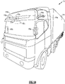
- FIG. 1A and 1B A schematic view of a commercial vehicle 10 is illustrated in Figures 1A and 1B .
- the vehicle 10 includes a vehicle cab or tractor 12 for pulling a trailer 14. Although a commercial truck is contemplated in this disclosure, the invention may also be applied to other types of vehicles.
- the vehicle 10 incorporates a camera mirror system (CMS) 15 ( Fig. 2 ) that has driver and passenger side camera arms 16a, 16b mounted to the outside of the vehicle cab 12.
- the camera arms 16a, 16b may include conventional mirrors integrated with them as well, although the CMS 15 can be used to entirely replace mirrors.
- each side can include multiple camera arms, each arm housing one or more cameras and/or mirrors.
- Each of the camera arms 16a, 16b includes a base that is secured to, for example, the cab 12.
- a pivoting arm is supported by the base and may articulate relative thereto.
- At least one rearward facing camera 20a, 20b is arranged respectively within camera arms.
- the exterior cameras 20a, 20b respectively provide an exterior field of view FOV EX1 , FOV EX2 that each include at least one of the Class II and Class IV views ( Fig. 1B ), which are legal prescribed views in the commercial trucking industry.
- the class II view on a given side of the vehicle 10 is a subset of the class IV view of the same side of the vehicle 10.
- Multiple cameras also may be used in each camera arm 16a, 16b to provide these views, if desired.
- Each arm 16a, 16b may also provide a housing that encloses electronics that are configured to provide various features of the CMS 15.
- First and second video displays 18a, 18b are arranged on each of the driver and passenger sides within the vehicle cab 12 on or near the A-pillars 19a, 19b to display Class II and Class IV views on its respective side of the vehicle 10, which provide rear facing side views along the vehicle 10 that are captured by the exterior cameras 20a, 20b.
- a camera housing 16c and camera 20c may be arranged at or near the front of the vehicle 10 to provide those views ( Fig. 1B ).
- a third display 18c arranged within the cab 12 near the top center of the windshield can be used to display the Class V and Class VI views, which are toward the front of the vehicle 10, to the driver.
- camera housings can be disposed at the sides and rear of the vehicle 10 to provide fields of view including some or all of the class VIII zones of the vehicle 10.
- the third display 18c can include one or more frames displaying the class VIII views.
- additional displays can be added near the first, second and third displays 18a, 18b, 18c and provide a display dedicated to providing a class VIII view.
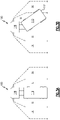
- Figures 3A and 3B illustrate a vehicle 100 in the process of executing a reversing maneuver.
- the trailer 110 In the initial position ( Figure 3A ) the trailer 110 has an initial angle of approximately zero degrees relative to the cab 120, meaning that it is aligned with the orientation of the cab 120. This angle can alternatively be expressed as 180 degrees relative to the cab 120.
- the trailer 110 skews relative the cab 120 ( Figure 3B ) creating a trailer angle that impacts reversing maneuvers.
- the particular skew of Figure 3B is exaggerated relative to most expected angles for the illustrative purposes.
- the vehicle 10, 100 illustrated herein includes an auto-panning feature within the camera mirror system.
- the auto-panning feature uses a combination of distinct trailer angle estimation and detection systems to estimate the trailer angle relative to the tractor at any given time.
- the estimated trailer angles are assigned a "weight" corresponding to how likely they are to be accurate given the current operating conditions and provided to a fusion system within the vehicle controller.
- a wheel detection-based system may have a high probability of accuracy (greater than 90%) in daylight conditions, when the black wheel stands out against the surrounding environment, and a low probability of accuracy (50-70%) in night time conditions when the black wheel blends in with the dark environment.
- a lane marker-based detection system such as a straight-line detection system using Hough transforms, may have a lower probability of accuracy in obscured weather conditions (rain, snow, fog, etc.) and a higher probability of accuracy in clear weather conditions
- a bottom edge detection system may have a high probability of accuracy with a container trailer but a low probability of accuracy with a tanker trailer.
- the vehicle controller fuses the multiple trailer angle estimates using a weighted sum based on the confidence value of each detection method.
- the weighted sum is referred to as a raw estimate.
- the raw estimate is then combined with historical estimates and filtered using a low pass filter to provide a smoothly transitioning trailer angle to the auto-panning feature in the CMS, as well as to any other vehicle systems that may benefit from utilizing the trailer angle estimate.
- the camera mirror system can generate meta information corresponding to the sides of the trailer, and the meta information can be utilized to prevent false positives and/or otherwise provide additional confidence for determined trailer angles.
- the low pass filter starts at the first measurement. This reduces the phase lag by providing an initial assigned value. While some delay is still present in such a system, the delay is minimized so as not to impact the reversing system.
- Figure 4 illustrates a process for determining a more accurate trailer angle.
- the process 300 determines angle estimates in a "Determine Angle Estimates" step 310.
- the number of angle estimates determined can vary depending on the particular system involved. In some examples, at least some of the angle estimates are purely vision based and utilize feature tracking of objects (e.g., wheels, rear edge, trailer markings, and the like) identified in the CMS video feeds to determine the estimated trailer angle. Similarly, some angle estimates can be determined based on deviation from road edge and/or lane detection, positioning satellite comparison to stored maps, hitch angle sensors, trailer edge detections, lane detectors, radar sensors, lidar sensors, and any other similar trailer angle detection systems.
- objects e.g., wheels, rear edge, trailer markings, and the like
- the controller determining the trailer angle estimates assigns a confidence value to each trailer angle estimate in a "Determine Confidence Values" step 320.
- the methodology for determining the confidence of each estimation depends on how the particular estimation is performed, and can be determined by one of skill in the art using any appropriate technique.
- the confidence values can be dependent on weather conditions, lighting conditions, trailer type, historical accuracy data, and any other features that may be relevant to a likelihood of accuracy.
- the confidence values are expressed as a percentage of accuracy (e.g. Wheel Based trailer angle of 15 degrees has a 94% chance of being accurate).
- the controller discards any estimates below a minimum confidence threshold in a "Discard Angles Below Confidence Threshold" step 330.
- estimates below an 85% confidence are assumed to be erroneous or otherwise inaccurate in some systems and are removed from consideration.
- estimates below a 90% confidence are assumed to be erroneous.
- Discarding estimates below the minimum confidence value threshold eliminates outliers that may occur due to inaccurate sensors, particularly bad conditions for a given estimation technique and any other similar conditions that result in inaccurate estimates. Elimination of extreme outliers increases the accuracy of the estimation. In some examples, where a significant number of estimates are provided to the controller and/or where a low confidence value is not indicative of an error, discarding the angles below the threshold can be omitted.
- a fusion algorithm in the controller determines a weighted sum of the angle estimates in a "Determine Weighted Sum" step 340.
- a first trailer angle estimate of 14 degrees has a confidence of 98%
- a second trailer angle estimate of 10 degrees has a confidence of 86%
- a third trailer angle estimate of 15 degrees has a confidence of 94%.
- the predefined threshold of confidence is set at 85%, and all three values are deemed to be acceptable.
- the fusion algorithm multiplies each angle by its corresponding confidence, sums the results, and divides the sum by a sum total of the confidence.
- the determined angle (alternately referred to as a raw measurement) is 13.10 degrees and this angle is the output to a low-pass filter.
- the low pass filtered angle is output to the auto-panning system. It is appreciated that practical implementations can utilize substantially more than three angle estimates, and the more angle estimates that are used, the more accurate the resulting value will be.
- the controller adds the weighted average to a historical data set including previously determined weighted averages of the current operation.
- the trailer angle estimates are performed approximately every 200 ms, and the historical data set includes each subsequent entry in order.
- a low pass filter is applied to the historical data set, including the newly determined weighted average. The low pass filter smooths the transition and eliminates "jerky” or "abrupt" trailer angle transitions, providing a more accurate representation of the trailer angle change over time and allowing the auto-panning system and/or any other vehicle systems to account for accurate changes.
- Figure 5 schematically illustrates an example auto-panning system for a vehicle 410.
- a controller 420 receives images and other sensor information from the vehicle 410, and the controller 420 determines raw angle estimates from the received images and sensor information using an angle detection module 424.
- a confidence value determination module 422 utilizes received data 421 indicative of conditions and any other aspects that impact the confidence of each detected angle.
- the confidence value determination module 422 determines the confidence of each trailer angle detection and the detections and confidence values are provided to a fusion module 426.
- the fusion module 426 determines the weighted average of the estimated trailer angles and fuses the weighted average with the previous trailer angles, which is stored in a trailer angle history 428.
- the fusion module 426 also applies the low pass filter to the combined trailer angle and historical trailer angle data to determine a two-dimensional trailer angle.
- the two-dimensional trailer angle is the accurate estimate of the current trailer angle on a two-dimensional plane.
- the two-dimensional trailer angle is converted to a three-dimensional trailer position based on the trailer angle, and the geographical features (e.g. hill grade).
- the three-dimensional trailer angle is then provided to an auto-panning feature and the camera mirror system automatically pans at least one camera view within the image.
- the automatic panning is configured to ensure that the rear edge of the trailer is maintained within the class II view throughout operations of the vehicle. In other implementations, the automatic panning can maintain other objects or portions of objects in the view.
- the fusion of multiple trailer angle estimations into a single value also allows for the system to account for unreliability of certain trailer angle estimation techniques for certain conditions and/or certain types of trailers while still reliably determining and panning for an accurate trailer angle.
Landscapes
- Engineering & Computer Science (AREA)
- Multimedia (AREA)
- Theoretical Computer Science (AREA)
- General Physics & Mathematics (AREA)
- Physics & Mathematics (AREA)
- Computer Vision & Pattern Recognition (AREA)
- Mechanical Engineering (AREA)
- Databases & Information Systems (AREA)
- Computing Systems (AREA)
- Evolutionary Computation (AREA)
- General Health & Medical Sciences (AREA)
- Medical Informatics (AREA)
- Software Systems (AREA)
- Artificial Intelligence (AREA)
- Health & Medical Sciences (AREA)
- Signal Processing (AREA)
- Quality & Reliability (AREA)
- Closed-Circuit Television Systems (AREA)
- Image Analysis (AREA)
Abstract
Description
- This disclosure relates to a camera mirror system (CMS) for use in a commercial truck, and in particular to a CMS having an auto-panning feature including fused trailer angle estimates.
- Mirror replacement systems, and camera systems for supplementing mirror views, are utilized in commercial vehicles to enhance the ability of a vehicle operator to see a surrounding environment. Camera mirror systems (CMS) utilize one or more cameras to provide an enhanced field of view to a vehicle operator. In some examples, the mirror replacement systems cover a larger field of view than a conventional mirror, or include views that are not fully obtainable via a conventional mirror.
- In certain operations, such as trailer reversing maneuvers, stationary views such as those provided by a fixed mirror or a fixed field of view camera may not provide a full view of the operation and desirable information that could be presented to the operator is not presented to the operator. Manual panning systems, where the operator manually adjusts a physical camera or mirror angle can require frequent stopping of the maneuver to adjust the view provided and can provide insufficient granularity to the adjustments.
- Some example systems attempt to minimize the issues with manual panning by implementing automatic or semi-automatic panning. Such systems rely on estimates of trailer angle that are potentially inaccurate and the kinematic models of vehicle operations, particularly in reversing operations, can have a difficult time accounting for the potential variability of the trailer angle estimates.
- An exemplary method for automatically panning a view for a commercial vehicle includes determining a plurality of estimated trailer angles, each estimated trailer angle being determined using a distinct estimation method, assigning a confidence value to each estimated trailer angle in the plurality of estimated trailer angles, determining a weighted sum of the plurality of estimate trailer angles, and automatically panning the view based at least in part on the weighted sum and a current vehicle operation.
- The method may further include adding the determined weighted sum to an ordered list of historical weighted sums and low pass filtering the ordered list.
- Automatically panning the view may be based on the filtered ordered list.
- The method may further include discarding any estimated trailer angles with a confidence value below a predetermined threshold after assigning the confidence value to each estimate trailer angle and before determining the weighted sum.
- The predetermined threshold may be at least 85%.
- The weighted sum may be determined by multiplying each trailer angle estimate by the corresponding confidence value to determine weighted estimates, summing the weighted estimates, and dividing the summed weighted estimates by a sum of the confidence values.
- The distinct estimation methods may include at least two of an image-based wheel detection, an image-based trailer rear edge angle detection, an image-based trailer marking angle detection, an image based wheel angle detection, a road edge deviation detection, a lane marker deviation detection, a hitch angle sensor, and a wheel angle sensor.
- Automatically panning the view may comprise adjusting a class II view within a class IV view.
- Automatically panning the view may comprise maintaining a rear edge of the trailer within the class II view.
- The method may further include continuously iterating the method, thereby generating real time trailer angle monitoring.
- Determining the plurality of estimated trailer angles, assigning the confidence value to each estimated trailer angle in the plurality of estimated trailer angles, and determining a weighted average of the plurality of estimated trailer angles may be performed within a camera mirror system controller of the vehicle.
- At least one of determining the plurality of estimated trailer angles, assigning the confidence value to each estimated trailer angle in the plurality of estimated trailer angles, and determining a weighted average of the plurality of estimated trailer angles may be performed remote from a camera mirror system controller and transmitted to the camera mirror system controller.
- In one exemplary embodiment a camera mirror system for a vehicle includes a first camera having a first field of view, a controller configured to receive the first field of view and output a subset of the first field of view to a first display, the controller including a trailer angle detection module configured to determine a plurality of trailer angle estimates, a confidence value module configured to determine a confidence value of each trailer angle estimate, and a fusion module configured to fuse the plurality of trailer angle estimates and the confidence values into a single trailer angle estimate, and automatically panning at least one view of the camera mirror system based at least in part on the single trailer angle estimate such that a feature of the trailer is maintained within the at least one view.
- The fusion module may be configured to determine a weighted sum trailer angle based on the plurality of trailer angle estimates and the corresponding confidence values.
- The fusion module may be further configured to add the weighted sum trailer angle to a historical weighted sum trailer angle data set and low pass filter the historical weighted sum trailer angle data set.
- Each trailer angle estimate in the plurality of trailer angle estimates may be determined via a distinct angle estimation method.
- The controller may be further configured to add the single trailer estimate to an ordered list of historical trailer angle estimates and low pass filter the ordered list.
- Automatic panning may be based at least in part on the low pass filtered ordered list.
- The disclosure can be further understood by reference to the following detailed description when considered in connection with the accompanying drawings wherein:
-
Figure 1A is a schematic front view of a commercial truck with a camera mirror system (CMS) used to provide at least Class II and Class IV views. -
Figure 1B is a schematic top elevational view of a commercial truck with a camera mirror system providing Class II, Class IV, Class V and Class VI views. -
Figure 2 is a schematic top perspective view of a vehicle cabin including displays and interior cameras. -
Figure 3A illustrates a vehicle at the initiation of a reverse maneuver, with no trailer angle. -
Figure 3B illustrates the vehicle mid reversing maneuver, with a high trailer angle. -
Figure 4 illustrates a method for obtaining an estimated weighted trailer angle. -
Figure 5 illustrates a system for determining an accurate trailer angle from the estimated weighted angle, and automatically panning a camera mirror system. - The embodiments, examples and alternatives of the preceding paragraphs, the claims, or the following description and drawings, including any of their various aspects or respective individual features, may be taken independently or in any combination. Features described in connection with one embodiment are applicable to all embodiments, unless such features are incompatible.
- A schematic view of a
commercial vehicle 10 is illustrated inFigures 1A and1B . Thevehicle 10 includes a vehicle cab ortractor 12 for pulling atrailer 14. Although a commercial truck is contemplated in this disclosure, the invention may also be applied to other types of vehicles. Thevehicle 10 incorporates a camera mirror system (CMS) 15 (Fig. 2 ) that has driver and passengerside camera arms vehicle cab 12. If desired, thecamera arms CMS 15 can be used to entirely replace mirrors. In additional examples, each side can include multiple camera arms, each arm housing one or more cameras and/or mirrors. - Each of the
camera arms cab 12. A pivoting arm is supported by the base and may articulate relative thereto. At least one rearward facingcamera exterior cameras Fig. 1B ), which are legal prescribed views in the commercial trucking industry. The class II view on a given side of thevehicle 10 is a subset of the class IV view of the same side of thevehicle 10. Multiple cameras also may be used in eachcamera arm arm CMS 15. - First and second video displays 18a, 18b are arranged on each of the driver and passenger sides within the
vehicle cab 12 on or near the A-pillars 19a, 19b to display Class II and Class IV views on its respective side of thevehicle 10, which provide rear facing side views along thevehicle 10 that are captured by theexterior cameras - If video of Class V and Class VI views are also desired, a
camera housing 16c andcamera 20c may be arranged at or near the front of thevehicle 10 to provide those views (Fig. 1B ). Athird display 18c arranged within thecab 12 near the top center of the windshield can be used to display the Class V and Class VI views, which are toward the front of thevehicle 10, to the driver. - If video of class VIII views is desired, camera housings can be disposed at the sides and rear of the
vehicle 10 to provide fields of view including some or all of the class VIII zones of thevehicle 10. In such examples, thethird display 18c can include one or more frames displaying the class VIII views. Alternatively, additional displays can be added near the first, second andthird displays - With continued reference to
Figures 1A ,1B and2 ,Figures 3A and 3B illustrate avehicle 100 in the process of executing a reversing maneuver. In the initial position (Figure 3A ) thetrailer 110 has an initial angle of approximately zero degrees relative to thecab 120, meaning that it is aligned with the orientation of thecab 120. This angle can alternatively be expressed as 180 degrees relative to thecab 120. During the process of reversing, and particularly when reversing through a turn, thetrailer 110 skews relative the cab 120 (Figure 3B ) creating a trailer angle that impacts reversing maneuvers. The particular skew ofFigure 3B is exaggerated relative to most expected angles for the illustrative purposes. - In order to assist the driver in making the reversing maneuver, it is beneficial to ensure that the rear 112 of the
trailer 110 is visible to the driver in at least one display through the reversing maneuver. In some particular examples, it is desirable to not only include the rear 112 of thetrailer 110, but also to center the class II view on the rear 112 of thetrailer 110. However, as illustrated inFigure 3B , a static class II view can result in the rear 112 of thetrailer 110 extending beyond the boundaries of the class II view even when the rear 112 remains within the Class IV field of view. In order to prevent loss of view of the rear 112 of thetrailer 110 in the class II view, or to maintain centering of the class II view on the rear 112 of thetrailer 110, thevehicle - The auto-panning feature uses a combination of distinct trailer angle estimation and detection systems to estimate the trailer angle relative to the tractor at any given time. The estimated trailer angles are assigned a "weight" corresponding to how likely they are to be accurate given the current operating conditions and provided to a fusion system within the vehicle controller. By way of example, a wheel detection-based system may have a high probability of accuracy (greater than 90%) in daylight conditions, when the black wheel stands out against the surrounding environment, and a low probability of accuracy (50-70%) in night time conditions when the black wheel blends in with the dark environment. Similarly, a lane marker-based detection system, such as a straight-line detection system using Hough transforms, may have a lower probability of accuracy in obscured weather conditions (rain, snow, fog, etc.) and a higher probability of accuracy in clear weather conditions, and a bottom edge detection system may have a high probability of accuracy with a container trailer but a low probability of accuracy with a tanker trailer.
- The vehicle controller fuses the multiple trailer angle estimates using a weighted sum based on the confidence value of each detection method. The weighted sum is referred to as a raw estimate. The raw estimate is then combined with historical estimates and filtered using a low pass filter to provide a smoothly transitioning trailer angle to the auto-panning feature in the CMS, as well as to any other vehicle systems that may benefit from utilizing the trailer angle estimate. In some examples, the camera mirror system can generate meta information corresponding to the sides of the trailer, and the meta information can be utilized to prevent false positives and/or otherwise provide additional confidence for determined trailer angles. In order to reduce phase lag, and thus reporting delay, when determining the trailer angle estimate to negligible levels the low pass filter starts at the first measurement. This reduces the phase lag by providing an initial assigned value. While some delay is still present in such a system, the delay is minimized so as not to impact the reversing system.
- With continued reference to
Figures 1-3B ,Figure 4 illustrates a process for determining a more accurate trailer angle. Initially, theprocess 300 determines angle estimates in a "Determine Angle Estimates"step 310. The number of angle estimates determined can vary depending on the particular system involved. In some examples, at least some of the angle estimates are purely vision based and utilize feature tracking of objects (e.g., wheels, rear edge, trailer markings, and the like) identified in the CMS video feeds to determine the estimated trailer angle. Similarly, some angle estimates can be determined based on deviation from road edge and/or lane detection, positioning satellite comparison to stored maps, hitch angle sensors, trailer edge detections, lane detectors, radar sensors, lidar sensors, and any other similar trailer angle detection systems. - Once the trailer angle estimates are determined, the controller determining the trailer angle estimates assigns a confidence value to each trailer angle estimate in a "Determine Confidence Values"
step 320. The methodology for determining the confidence of each estimation depends on how the particular estimation is performed, and can be determined by one of skill in the art using any appropriate technique. In some examples, the confidence values can be dependent on weather conditions, lighting conditions, trailer type, historical accuracy data, and any other features that may be relevant to a likelihood of accuracy. The confidence values are expressed as a percentage of accuracy (e.g. Wheel Based trailer angle of 15 degrees has a 94% chance of being accurate). - After determining the confidence values, the controller discards any estimates below a minimum confidence threshold in a "Discard Angles Below Confidence Threshold"
step 330. In one example, estimates below an 85% confidence are assumed to be erroneous or otherwise inaccurate in some systems and are removed from consideration. In another example, estimates below a 90% confidence are assumed to be erroneous. Discarding estimates below the minimum confidence value threshold eliminates outliers that may occur due to inaccurate sensors, particularly bad conditions for a given estimation technique and any other similar conditions that result in inaccurate estimates. Elimination of extreme outliers increases the accuracy of the estimation. In some examples, where a significant number of estimates are provided to the controller and/or where a low confidence value is not indicative of an error, discarding the angles below the threshold can be omitted. - After all estimates below the threshold are discarded, or step 330 is bypassed, a fusion algorithm in the controller determines a weighted sum of the angle estimates in a "Determine Weighted Sum"
step 340. In one example of the weighted average determination, a first trailer angle estimate of 14 degrees has a confidence of 98%, a second trailer angle estimate of 10 degrees has a confidence of 86%, and a third trailer angle estimate of 15 degrees has a confidence of 94%. The predefined threshold of confidence is set at 85%, and all three values are deemed to be acceptable. The fusion algorithm multiplies each angle by its corresponding confidence, sums the results, and divides the sum by a sum total of the confidence. In the exemplary case, the fusion algorithm results in the following: ((14∗98)+(10∗86)+(15∗94))/(98+86+94) =13.10 degrees. Thus, in the exemplary case, the determined angle (alternately referred to as a raw measurement) is 13.10 degrees and this angle is the output to a low-pass filter. The low pass filtered angle is output to the auto-panning system. It is appreciated that practical implementations can utilize substantially more than three angle estimates, and the more angle estimates that are used, the more accurate the resulting value will be. - Once the weighted average of the estimated angle has been determined, the controller adds the weighted average to a historical data set including previously determined weighted averages of the current operation. In one example, the trailer angle estimates are performed approximately every 200 ms, and the historical data set includes each subsequent entry in order. A low pass filter is applied to the historical data set, including the newly determined weighted average. The low pass filter smooths the transition and eliminates "jerky" or "abrupt" trailer angle transitions, providing a more accurate representation of the trailer angle change over time and allowing the auto-panning system and/or any other vehicle systems to account for accurate changes.
- With continued reference to
Figure 4 ,Figure 5 schematically illustrates an example auto-panning system for avehicle 410. Acontroller 420 receives images and other sensor information from thevehicle 410, and thecontroller 420 determines raw angle estimates from the received images and sensor information using anangle detection module 424. Alongside theangle detection module 424, a confidence value determination module 422 utilizes receiveddata 421 indicative of conditions and any other aspects that impact the confidence of each detected angle. The confidence value determination module 422 determines the confidence of each trailer angle detection and the detections and confidence values are provided to afusion module 426. - The
fusion module 426 determines the weighted average of the estimated trailer angles and fuses the weighted average with the previous trailer angles, which is stored in atrailer angle history 428. Thefusion module 426 also applies the low pass filter to the combined trailer angle and historical trailer angle data to determine a two-dimensional trailer angle. The two-dimensional trailer angle is the accurate estimate of the current trailer angle on a two-dimensional plane. The two-dimensional trailer angle is converted to a three-dimensional trailer position based on the trailer angle, and the geographical features (e.g. hill grade). The three-dimensional trailer angle is then provided to an auto-panning feature and the camera mirror system automatically pans at least one camera view within the image. In one example, the automatic panning is configured to ensure that the rear edge of the trailer is maintained within the class II view throughout operations of the vehicle. In other implementations, the automatic panning can maintain other objects or portions of objects in the view. - The fusion of the multiple estimate angles from different sources into a single, more reliable, trailer angle estimate that can be used across multiple systems. The fusion of multiple trailer angle estimations into a single value also allows for the system to account for unreliability of certain trailer angle estimation techniques for certain conditions and/or certain types of trailers while still reliably determining and panning for an accurate trailer angle.
- Although an example embodiment has been disclosed, a worker of ordinary skill in this art would recognize that certain modifications would come within the scope of the claims. For that reason, the following claims should be studied to determine their true scope and content.
Claims (15)
- A method for automatically panning a view for a commercial vehicle (10) comprising:determining a plurality of estimated trailer angles, each estimated trailer angle being determined using a distinct estimation method;assigning a confidence value to each estimated trailer angle in the plurality of estimated trailer angles;determining a weighted sum of the plurality of estimate trailer angles; andautomatically panning the view based at least in part on the weighted sum and a current vehicle operation.
- The method of claim 1, further comprising adding the determined weighted sum to an ordered list of historical weighted sums and low pass filtering the ordered list.
- The method of claim 2, wherein automatically panning the view is based on the filtered ordered list.
- The method of any preceding claim, further comprising discarding any estimated trailer angles with a confidence value below a predetermined threshold after assigning the confidence value to each estimate trailer angle and before determining the weighted sum, optionally wherein the predetermined threshold is at least 85%.
- The method of any preceding claim, wherein the weighted sum is determined by multiplying each trailer angle estimate by the corresponding confidence value to determine weighted estimates, summing the weighted estimates, and dividing the summed weighted estimates by a sum of the confidence values.
- The method of any preceding claim, wherein the distinct estimation methods include at least two of an image-based wheel detection, an image-based trailer rear edge angle detection, an image-based trailer marking angle detection, an image based wheel angle detection, a road edge deviation detection, a lane marker deviation detection, a hitch angle sensor, and a wheel angle sensor.
- The method of any preceding claim, wherein automatically panning the view comprises adjusting a class II view within a class IV view, optionally wherein automatically panning the view comprises maintaining a rear edge of the trailer within the class II view.
- The method of any preceding claim, further comprising continuously iterating the method, thereby generating real time trailer angle monitoring.
- The method of any preceding claim, wherein determining the plurality of estimated trailer angles, assigning the confidence value to each estimated trailer angle in the plurality of estimated trailer angles, and determining a weighted average of the plurality of estimated trailer angles is performed within a camera mirror system controller of the vehicle (10).
- The method of any preceding claim, wherein at least one of determining the plurality of estimated trailer angles, assigning the confidence value to each estimated trailer angle in the plurality of estimated trailer angles, and determining a weighted average of the plurality of estimated trailer angles is performed remote from a camera mirror system controller and transmitted to the camera mirror system controller.
- A camera mirror system (15) for a vehicle (410) comprising;a first camera (20a) having a first field of view (FOVEX1);a controller (420) configured to receive the first field of view (FOVEX1) and output a subset of the first field (FOVEX1) of view to a first display (18a);the controller (420) including a trailer angle detection module (424) configured to determine a plurality of trailer angle estimates, a confidence value module (422) configured to determine a confidence value of each trailer angle estimate, and a fusion module (426) configured to fuse the plurality of trailer angle estimates and the confidence values into a single trailer angle estimate; andautomatically panning at least one view of the camera mirror system (15) based at least in part on the single trailer angle estimate such that a feature of the trailer is maintained within the at least one view.
- The camera mirror system (15) of claim 11, wherein the fusion module (426) is configured to determine a weighted sum trailer angle based on the plurality of trailer angle estimates and the corresponding confidence values.
- The camera mirror system (15) of claim 12, wherein the fusion module (426) is further configured to add the weighted sum trailer angle to a historical weighted sum trailer angle data set (428) and low pass filter the historical weighted sum trailer angle data set.
- The camera mirror system (15) of any one of claims 11 to 13 wherein each trailer angle estimate in the plurality of trailer angle estimates is determined via a distinct angle estimation method.
- The camera mirror system (15) of any one of claims 11 to14, wherein the controller (420) is further configured to add the single trailer estimate to an ordered list of historical trailer angle estimates and low pass filter the ordered list, optionally wherein the automatic panning is based at least in part on the low pass filtered ordered list.
Applications Claiming Priority (2)
| Application Number | Priority Date | Filing Date | Title |
|---|---|---|---|
| US202163209006P | 2021-06-10 | 2021-06-10 | |
| US17/723,775 US11780371B2 (en) | 2021-06-10 | 2022-04-19 | Auto panning camera mirror system including weighted trailer angle estimation |
Publications (2)
| Publication Number | Publication Date |
|---|---|
| EP4101698A1 true EP4101698A1 (en) | 2022-12-14 |
| EP4101698B1 EP4101698B1 (en) | 2025-09-03 |
Family
ID=81585689
Family Applications (1)
| Application Number | Title | Priority Date | Filing Date |
|---|---|---|---|
| EP22171931.3A Active EP4101698B1 (en) | 2021-06-10 | 2022-05-05 | Auto panning camera mirror system including weighted trailer angle estimation |
Country Status (4)
| Country | Link |
|---|---|
| US (1) | US11780371B2 (en) |
| EP (1) | EP4101698B1 (en) |
| JP (1) | JP7778640B2 (en) |
| CN (1) | CN115471445B (en) |
Families Citing this family (8)
| Publication number | Priority date | Publication date | Assignee | Title |
|---|---|---|---|---|
| DE102021131824B3 (en) * | 2021-12-02 | 2023-03-30 | Motherson Innovations Company Limited | Camera wing system, vehicle therewith and method of operation thereof |
| EP4190637B1 (en) * | 2021-12-02 | 2025-08-06 | Motherson Innovations Company Ltd. | Vehicle tracking for a camera wing system |
| WO2025015258A2 (en) * | 2023-07-12 | 2025-01-16 | Clear View Mirror, Llc | Vehicle safety system having lidar technology |
| US12565179B2 (en) * | 2023-08-11 | 2026-03-03 | Bendix Commercial Vehicle Systems Llc | Trailer sway detection and braking distribution using a camera mirror system |
| US12485861B2 (en) | 2023-08-11 | 2025-12-02 | Bendix Commercial Vehicle Systems Llc | Trailer sway detection and mitigation using a camera mirror system |
| US12466323B2 (en) | 2024-01-11 | 2025-11-11 | Stoneridge Electronics Ab | Method and apparatus for determining trailer angle |
| DE102024105726A1 (en) | 2024-02-29 | 2025-09-04 | Daimler Truck AG | Method for detecting an edge of a trailer of a vehicle combination to determine a bending angle |
| US20250303966A1 (en) * | 2024-03-28 | 2025-10-02 | Fca Us Llc | Vehicle display system |
Citations (4)
| Publication number | Priority date | Publication date | Assignee | Title |
|---|---|---|---|---|
| US20150002670A1 (en) * | 2013-06-28 | 2015-01-01 | Magna Electronics Inc. | Trailering assist system for vehicle |
| US20190016264A1 (en) * | 2017-07-14 | 2019-01-17 | Magna Electronics Inc. | Trailer angle detection using rear backup camera |
| US20200346581A1 (en) * | 2019-05-02 | 2020-11-05 | Jared Lawson | Trailer tracking commercial vehicle and automotive side view mirror system |
| EP4070996A1 (en) * | 2021-04-05 | 2022-10-12 | Stoneridge, Inc. | Auto panning camera mirror system including image based trailer angle detection |
Family Cites Families (14)
| Publication number | Priority date | Publication date | Assignee | Title |
|---|---|---|---|---|
| US10011228B2 (en) * | 2015-12-17 | 2018-07-03 | Ford Global Technologies, Llc | Hitch angle detection for trailer backup assist system using multiple imaging devices |
| US9610975B1 (en) * | 2015-12-17 | 2017-04-04 | Ford Global Technologies, Llc | Hitch angle detection for trailer backup assist system |
| US10011299B2 (en) * | 2016-04-21 | 2018-07-03 | Robert Bosch Gmbh | Trailer angle detection using rear camera |
| US10638025B2 (en) * | 2017-03-22 | 2020-04-28 | Magna Electronics Inc. | Vehicular trailering assist sytem |
| US10633023B2 (en) * | 2017-10-23 | 2020-04-28 | Ford Global Technologies, Llc | System and method for trailer-car initial hitching angle detection by force-based sensing system |
| GB201806279D0 (en) * | 2018-04-17 | 2018-05-30 | Cambridge Entpr Ltd | Method and system of articulation angle measurement |
| US11050933B2 (en) * | 2018-04-27 | 2021-06-29 | Continenal Automotive Systems, Inc. | Device and method for determining a center of a trailer tow coupler |
| JP7230964B2 (en) | 2018-08-06 | 2023-03-01 | ソニーグループ株式会社 | Information processing device, information processing method, and program |
| US10942271B2 (en) * | 2018-10-30 | 2021-03-09 | Tusimple, Inc. | Determining an angle between a tow vehicle and a trailer |
| US10829046B2 (en) * | 2019-03-06 | 2020-11-10 | Ford Global Technologies, Llc | Trailer angle detection using end-to-end learning |
| US12214822B2 (en) * | 2019-06-28 | 2025-02-04 | Magna Electronics Inc. | Trailer assist system with enhanced beam length estimation |
| CN110949268A (en) | 2019-12-17 | 2020-04-03 | 北京行易道科技有限公司 | Lateral radar of trailer, and method, device and system for adjusting forward radar of vehicle |
| DE102020107789B4 (en) | 2020-03-20 | 2025-04-03 | Mekra Lang Gmbh & Co. Kg | Vision system for a vehicle and method for switching between image areas displayed by the vision system |
| US20220346581A1 (en) | 2021-05-03 | 2022-11-03 | Interface, Inc. | Flooring tile collections and methods of making and installing same |
-
2022
- 2022-04-19 US US17/723,775 patent/US11780371B2/en active Active
- 2022-05-05 EP EP22171931.3A patent/EP4101698B1/en active Active
- 2022-05-18 JP JP2022081368A patent/JP7778640B2/en active Active
- 2022-06-09 CN CN202210654177.8A patent/CN115471445B/en active Active
Patent Citations (4)
| Publication number | Priority date | Publication date | Assignee | Title |
|---|---|---|---|---|
| US20150002670A1 (en) * | 2013-06-28 | 2015-01-01 | Magna Electronics Inc. | Trailering assist system for vehicle |
| US20190016264A1 (en) * | 2017-07-14 | 2019-01-17 | Magna Electronics Inc. | Trailer angle detection using rear backup camera |
| US20200346581A1 (en) * | 2019-05-02 | 2020-11-05 | Jared Lawson | Trailer tracking commercial vehicle and automotive side view mirror system |
| EP4070996A1 (en) * | 2021-04-05 | 2022-10-12 | Stoneridge, Inc. | Auto panning camera mirror system including image based trailer angle detection |
Also Published As
| Publication number | Publication date |
|---|---|
| US11780371B2 (en) | 2023-10-10 |
| CN115471445A (en) | 2022-12-13 |
| JP7778640B2 (en) | 2025-12-02 |
| CN115471445B (en) | 2025-07-18 |
| EP4101698B1 (en) | 2025-09-03 |
| JP2022189740A (en) | 2022-12-22 |
| US20220396209A1 (en) | 2022-12-15 |
Similar Documents
| Publication | Publication Date | Title |
|---|---|---|
| EP4101698B1 (en) | Auto panning camera mirror system including weighted trailer angle estimation | |
| US11745659B2 (en) | Vehicular system for controlling vehicle | |
| US10509972B2 (en) | Vehicular vision system | |
| US9916699B2 (en) | Process for determining state of a vehicle | |
| US20200001856A1 (en) | Vehicular control system with vehicle trajectory tracking | |
| US20200017143A1 (en) | Vehicular trailer assist system | |
| US9340227B2 (en) | Vehicle lane keep assist system | |
| EP3161507B1 (en) | Method for tracking a target vehicle approaching a motor vehicle by means of a camera system of the motor vehicle, camera system and motor vehicle | |
| EP4170590A1 (en) | Trailer end tracking in a commercial vehicle camera mirror system | |
| US20220176960A1 (en) | Vehicular control system with vehicle control based on stored target object position and heading information | |
| US20240383479A1 (en) | Vehicular sensing system with lateral threat assessment | |
| EP4290876A1 (en) | Auto panning camera monitoring system including image based trailer angle detection | |
| BR102022010050B1 (en) | METHOD FOR AUTOMATICALLY PANORAMIC VIEW FOR COMMERCIAL VEHICLE AND VEHICLE CAMERA MIRROR SYSTEM | |
| BR102022010050A2 (en) | AUTOMATIC PANORAMIC CAMERA MIRROR SYSTEM INCLUDING WEIGHTED ESTIMATE OF TOWING ANGLE | |
| US20240402334A1 (en) | Vehicular blind spot monitoring system with enhanced lane and road edge determination | |
| EP4633179A1 (en) | An electronic side camera system and control method for front and back view |
Legal Events
| Date | Code | Title | Description |
|---|---|---|---|
| PUAI | Public reference made under article 153(3) epc to a published international application that has entered the european phase |
Free format text: ORIGINAL CODE: 0009012 |
|
| STAA | Information on the status of an ep patent application or granted ep patent |
Free format text: STATUS: THE APPLICATION HAS BEEN PUBLISHED |
|
| AK | Designated contracting states |
Kind code of ref document: A1 Designated state(s): AL AT BE BG CH CY CZ DE DK EE ES FI FR GB GR HR HU IE IS IT LI LT LU LV MC MK MT NL NO PL PT RO RS SE SI SK SM TR |
|
| STAA | Information on the status of an ep patent application or granted ep patent |
Free format text: STATUS: REQUEST FOR EXAMINATION WAS MADE |
|
| 17P | Request for examination filed |
Effective date: 20230126 |
|
| RBV | Designated contracting states (corrected) |
Designated state(s): AL AT BE BG CH CY CZ DE DK EE ES FI FR GB GR HR HU IE IS IT LI LT LU LV MC MK MT NL NO PL PT RO RS SE SI SK SM TR |
|
| P01 | Opt-out of the competence of the unified patent court (upc) registered |
Effective date: 20230529 |
|
| STAA | Information on the status of an ep patent application or granted ep patent |
Free format text: STATUS: EXAMINATION IS IN PROGRESS |
|
| 17Q | First examination report despatched |
Effective date: 20240703 |
|
| GRAP | Despatch of communication of intention to grant a patent |
Free format text: ORIGINAL CODE: EPIDOSNIGR1 |
|
| GRAJ | Information related to disapproval of communication of intention to grant by the applicant or resumption of examination proceedings by the epo deleted |
Free format text: ORIGINAL CODE: EPIDOSDIGR1 |
|
| GRAP | Despatch of communication of intention to grant a patent |
Free format text: ORIGINAL CODE: EPIDOSNIGR1 |
|
| STAA | Information on the status of an ep patent application or granted ep patent |
Free format text: STATUS: GRANT OF PATENT IS INTENDED |
|
| INTG | Intention to grant announced |
Effective date: 20250328 |
|
| GRAS | Grant fee paid |
Free format text: ORIGINAL CODE: EPIDOSNIGR3 |
|
| GRAA | (expected) grant |
Free format text: ORIGINAL CODE: 0009210 |
|
| STAA | Information on the status of an ep patent application or granted ep patent |
Free format text: STATUS: THE PATENT HAS BEEN GRANTED |
|
| AK | Designated contracting states |
Kind code of ref document: B1 Designated state(s): AL AT BE BG CH CY CZ DE DK EE ES FI FR GB GR HR HU IE IS IT LI LT LU LV MC MK MT NL NO PL PT RO RS SE SI SK SM TR |
|
| REG | Reference to a national code |
Ref country code: CH Ref legal event code: EP |
|
| REG | Reference to a national code |
Ref country code: DE Ref legal event code: R096 Ref document number: 602022020549 Country of ref document: DE |
|
| REG | Reference to a national code |
Ref country code: SE Ref legal event code: TRGR |
|
| REG | Reference to a national code |
Ref country code: IE Ref legal event code: FG4D |
|
| REG | Reference to a national code |
Ref country code: NL Ref legal event code: MP Effective date: 20250903 |
|
| PG25 | Lapsed in a contracting state [announced via postgrant information from national office to epo] |
Ref country code: NO Free format text: LAPSE BECAUSE OF FAILURE TO SUBMIT A TRANSLATION OF THE DESCRIPTION OR TO PAY THE FEE WITHIN THE PRESCRIBED TIME-LIMIT Effective date: 20251203 |
|
| REG | Reference to a national code |
Ref country code: LT Ref legal event code: MG9D |
|
| PG25 | Lapsed in a contracting state [announced via postgrant information from national office to epo] |
Ref country code: FI Free format text: LAPSE BECAUSE OF FAILURE TO SUBMIT A TRANSLATION OF THE DESCRIPTION OR TO PAY THE FEE WITHIN THE PRESCRIBED TIME-LIMIT Effective date: 20250903 |
|
| PG25 | Lapsed in a contracting state [announced via postgrant information from national office to epo] |
Ref country code: HR Free format text: LAPSE BECAUSE OF FAILURE TO SUBMIT A TRANSLATION OF THE DESCRIPTION OR TO PAY THE FEE WITHIN THE PRESCRIBED TIME-LIMIT Effective date: 20250903 |
|
| PG25 | Lapsed in a contracting state [announced via postgrant information from national office to epo] |
Ref country code: GR Free format text: LAPSE BECAUSE OF FAILURE TO SUBMIT A TRANSLATION OF THE DESCRIPTION OR TO PAY THE FEE WITHIN THE PRESCRIBED TIME-LIMIT Effective date: 20251204 |
|
| PG25 | Lapsed in a contracting state [announced via postgrant information from national office to epo] |
Ref country code: LV Free format text: LAPSE BECAUSE OF FAILURE TO SUBMIT A TRANSLATION OF THE DESCRIPTION OR TO PAY THE FEE WITHIN THE PRESCRIBED TIME-LIMIT Effective date: 20250903 |
|
| PG25 | Lapsed in a contracting state [announced via postgrant information from national office to epo] |
Ref country code: BG Free format text: LAPSE BECAUSE OF FAILURE TO SUBMIT A TRANSLATION OF THE DESCRIPTION OR TO PAY THE FEE WITHIN THE PRESCRIBED TIME-LIMIT Effective date: 20250903 Ref country code: PL Free format text: LAPSE BECAUSE OF FAILURE TO SUBMIT A TRANSLATION OF THE DESCRIPTION OR TO PAY THE FEE WITHIN THE PRESCRIBED TIME-LIMIT Effective date: 20250903 |
|
| PG25 | Lapsed in a contracting state [announced via postgrant information from national office to epo] |
Ref country code: RS Free format text: LAPSE BECAUSE OF FAILURE TO SUBMIT A TRANSLATION OF THE DESCRIPTION OR TO PAY THE FEE WITHIN THE PRESCRIBED TIME-LIMIT Effective date: 20251203 |
|
| PG25 | Lapsed in a contracting state [announced via postgrant information from national office to epo] |
Ref country code: ES Free format text: LAPSE BECAUSE OF FAILURE TO SUBMIT A TRANSLATION OF THE DESCRIPTION OR TO PAY THE FEE WITHIN THE PRESCRIBED TIME-LIMIT Effective date: 20250903 |
|
| REG | Reference to a national code |
Ref country code: AT Ref legal event code: MK05 Ref document number: 1832653 Country of ref document: AT Kind code of ref document: T Effective date: 20250903 |
|
| PG25 | Lapsed in a contracting state [announced via postgrant information from national office to epo] |
Ref country code: NL Free format text: LAPSE BECAUSE OF FAILURE TO SUBMIT A TRANSLATION OF THE DESCRIPTION OR TO PAY THE FEE WITHIN THE PRESCRIBED TIME-LIMIT Effective date: 20250903 |
|
| PG25 | Lapsed in a contracting state [announced via postgrant information from national office to epo] |
Ref country code: SM Free format text: LAPSE BECAUSE OF FAILURE TO SUBMIT A TRANSLATION OF THE DESCRIPTION OR TO PAY THE FEE WITHIN THE PRESCRIBED TIME-LIMIT Effective date: 20250903 |
|
| PG25 | Lapsed in a contracting state [announced via postgrant information from national office to epo] |
Ref country code: AT Free format text: LAPSE BECAUSE OF FAILURE TO SUBMIT A TRANSLATION OF THE DESCRIPTION OR TO PAY THE FEE WITHIN THE PRESCRIBED TIME-LIMIT Effective date: 20250903 |
|
| PG25 | Lapsed in a contracting state [announced via postgrant information from national office to epo] |
Ref country code: IT Free format text: LAPSE BECAUSE OF FAILURE TO SUBMIT A TRANSLATION OF THE DESCRIPTION OR TO PAY THE FEE WITHIN THE PRESCRIBED TIME-LIMIT Effective date: 20250903 |
|
| PG25 | Lapsed in a contracting state [announced via postgrant information from national office to epo] |
Ref country code: IS Free format text: LAPSE BECAUSE OF FAILURE TO SUBMIT A TRANSLATION OF THE DESCRIPTION OR TO PAY THE FEE WITHIN THE PRESCRIBED TIME-LIMIT Effective date: 20260103 |
|
| PG25 | Lapsed in a contracting state [announced via postgrant information from national office to epo] |
Ref country code: PT Free format text: LAPSE BECAUSE OF FAILURE TO SUBMIT A TRANSLATION OF THE DESCRIPTION OR TO PAY THE FEE WITHIN THE PRESCRIBED TIME-LIMIT Effective date: 20260105 Ref country code: CZ Free format text: LAPSE BECAUSE OF FAILURE TO SUBMIT A TRANSLATION OF THE DESCRIPTION OR TO PAY THE FEE WITHIN THE PRESCRIBED TIME-LIMIT Effective date: 20250903 |
|
| PG25 | Lapsed in a contracting state [announced via postgrant information from national office to epo] |
Ref country code: SK Free format text: LAPSE BECAUSE OF FAILURE TO SUBMIT A TRANSLATION OF THE DESCRIPTION OR TO PAY THE FEE WITHIN THE PRESCRIBED TIME-LIMIT Effective date: 20250903 Ref country code: EE Free format text: LAPSE BECAUSE OF FAILURE TO SUBMIT A TRANSLATION OF THE DESCRIPTION OR TO PAY THE FEE WITHIN THE PRESCRIBED TIME-LIMIT Effective date: 20250903 |