EP4101686A1 - Distribution de puissance d'un moteur électrique hybride - Google Patents
Distribution de puissance d'un moteur électrique hybride Download PDFInfo
- Publication number
- EP4101686A1 EP4101686A1 EP22178725.2A EP22178725A EP4101686A1 EP 4101686 A1 EP4101686 A1 EP 4101686A1 EP 22178725 A EP22178725 A EP 22178725A EP 4101686 A1 EP4101686 A1 EP 4101686A1
- Authority
- EP
- European Patent Office
- Prior art keywords
- flight
- battery
- aircraft
- data
- waypoints
- Prior art date
- Legal status (The legal status is an assumption and is not a legal conclusion. Google has not performed a legal analysis and makes no representation as to the accuracy of the status listed.)
- Pending
Links
Images


Classifications
-
- H—ELECTRICITY
- H02—GENERATION; CONVERSION OR DISTRIBUTION OF ELECTRIC POWER
- H02J—CIRCUIT ARRANGEMENTS OR SYSTEMS FOR SUPPLYING OR DISTRIBUTING ELECTRIC POWER; SYSTEMS FOR STORING ELECTRIC ENERGY
- H02J7/00—Circuit arrangements for charging or depolarising batteries or for supplying loads from batteries
- H02J7/14—Circuit arrangements for charging or depolarising batteries or for supplying loads from batteries for charging batteries from dynamo-electric generators driven at varying speed, e.g. on vehicle
- H02J7/1446—Circuit arrangements for charging or depolarising batteries or for supplying loads from batteries for charging batteries from dynamo-electric generators driven at varying speed, e.g. on vehicle in response to parameters of a vehicle
-
- G—PHYSICS
- G08—SIGNALLING
- G08G—TRAFFIC CONTROL SYSTEMS
- G08G5/00—Traffic control systems for aircraft, e.g. air-traffic control [ATC]
- G08G5/003—Flight plan management
- G08G5/0039—Modification of a flight plan
-
- B—PERFORMING OPERATIONS; TRANSPORTING
- B60—VEHICLES IN GENERAL
- B60L—PROPULSION OF ELECTRICALLY-PROPELLED VEHICLES; SUPPLYING ELECTRIC POWER FOR AUXILIARY EQUIPMENT OF ELECTRICALLY-PROPELLED VEHICLES; ELECTRODYNAMIC BRAKE SYSTEMS FOR VEHICLES IN GENERAL; MAGNETIC SUSPENSION OR LEVITATION FOR VEHICLES; MONITORING OPERATING VARIABLES OF ELECTRICALLY-PROPELLED VEHICLES; ELECTRIC SAFETY DEVICES FOR ELECTRICALLY-PROPELLED VEHICLES
- B60L58/00—Methods or circuit arrangements for monitoring or controlling batteries or fuel cells, specially adapted for electric vehicles
- B60L58/10—Methods or circuit arrangements for monitoring or controlling batteries or fuel cells, specially adapted for electric vehicles for monitoring or controlling batteries
- B60L58/12—Methods or circuit arrangements for monitoring or controlling batteries or fuel cells, specially adapted for electric vehicles for monitoring or controlling batteries responding to state of charge [SoC]
- B60L58/13—Maintaining the SoC within a determined range
-
- H—ELECTRICITY
- H02—GENERATION; CONVERSION OR DISTRIBUTION OF ELECTRIC POWER
- H02J—CIRCUIT ARRANGEMENTS OR SYSTEMS FOR SUPPLYING OR DISTRIBUTING ELECTRIC POWER; SYSTEMS FOR STORING ELECTRIC ENERGY
- H02J7/00—Circuit arrangements for charging or depolarising batteries or for supplying loads from batteries
- H02J7/0063—Circuit arrangements for charging or depolarising batteries or for supplying loads from batteries with circuits adapted for supplying loads from the battery
-
- H—ELECTRICITY
- H02—GENERATION; CONVERSION OR DISTRIBUTION OF ELECTRIC POWER
- H02J—CIRCUIT ARRANGEMENTS OR SYSTEMS FOR SUPPLYING OR DISTRIBUTING ELECTRIC POWER; SYSTEMS FOR STORING ELECTRIC ENERGY
- H02J2310/00—The network for supplying or distributing electric power characterised by its spatial reach or by the load
- H02J2310/40—The network being an on-board power network, i.e. within a vehicle
- H02J2310/48—The network being an on-board power network, i.e. within a vehicle for electric vehicles [EV] or hybrid vehicles [HEV]
-
- Y—GENERAL TAGGING OF NEW TECHNOLOGICAL DEVELOPMENTS; GENERAL TAGGING OF CROSS-SECTIONAL TECHNOLOGIES SPANNING OVER SEVERAL SECTIONS OF THE IPC; TECHNICAL SUBJECTS COVERED BY FORMER USPC CROSS-REFERENCE ART COLLECTIONS [XRACs] AND DIGESTS
- Y02—TECHNOLOGIES OR APPLICATIONS FOR MITIGATION OR ADAPTATION AGAINST CLIMATE CHANGE
- Y02T—CLIMATE CHANGE MITIGATION TECHNOLOGIES RELATED TO TRANSPORTATION
- Y02T50/00—Aeronautics or air transport
- Y02T50/60—Efficient propulsion technologies, e.g. for aircraft
Definitions
- the subject matter disclosed herein generally relates to turbine engines and, more particularly, to hybrid electric engine power distribution.
- a hybrid electric gas turbine engine can use electricity and/or liquid fuel (e.g., jet fuel) to provide thrust to an aircraft.
- Hybrid electric engines can selectively use electricity or gas, depending, for example, on a flight stage, environmental conditions, and other concerns. For example, during times that require significant thrust (e.g., take off, climb, etc.), it may be more efficient to use liquid fuel to power the hybrid electric engine. However, at other times that require less thrust (e.g., taxi, cruise, descent, etc.), it may be more efficient to use electricity to power the hybrid electric engine.
- a computer-implemented method for managing battery usage for a hybrid electric engine of an aircraft includes receiving a flight plan comprising flight plan data for a flight of an aircraft.
- the method further includes receiving battery data about a battery system of the aircraft.
- the method further includes determining waypoints for when to apply electric power from the battery system based at least in part on the flight plan data and the battery data.
- the method further includes controlling, based at least in part on the waypoints, an electric motor while the flight plan is executed.
- the method further includes updating, while the flight plan is executed, the waypoints based at least in part on data received during the flight.
- determining the waypoints further includes: prioritizing the waypoints based at least in part on an amount of expected fuel savings.
- further embodiments may include that the prioritizing is further based at least in part on a fuel price.
- further embodiments may include that the prioritizing is further based at least in part on an efficiency ratio between fuel and electric power.
- further embodiments may include that updating the waypoints includes: identifying a climb boost opportunity based at least in part on the data received during the flight and the battery data
- further embodiments may include that the flight plan data defines a plurality of flight events, wherein the plurality of flight events comprises a taxi out event, a takeoff event, a climb event, a cruise event, a descent event, and a taxi back event.
- determining the waypoints comprises assigning a priority to each of the flight events relative to the other of the plurality of flight events.
- a controller includes processing circuitry.
- the processing circuitry is configured to receive a flight plan comprising flight plan data for a flight of an aircraft.
- the processing circuitry is further configured to receive battery data about a battery system of the aircraft.
- the processing circuitry is further configured to determine waypoints for when to apply electric power from the battery system based at least in part on the flight plan data and the battery data.
- the processing circuitry is further configured to control, based at least in part on the waypoints, an electric motor while the flight plan is executed.
- the processing circuitry is further configured to update, while the flight plan is executed, the waypoints based at least in part on data received during the flight.
- determining the waypoints further includes: prioritizing the waypoints based at least in part on an amount of expected fuel savings.
- further embodiments may include that the prioritizing is further based at least in part on a fuel price.
- further embodiments may include that the prioritizing is further based at least in part on an efficiency ratio between fuel and electric power.
- further embodiments may include that updating the waypoints includes: identifying a climb boost opportunity based at least in part on the data received during the flight and the battery data.
- further embodiments may include that the flight plan data defines a plurality of flight events, wherein the plurality of flight events comprises a taxi out event, a takeoff event, a climb event, a cruise event, a descent event, and a taxi back event, and wherein determining the waypoints comprises assigning a priority to each of the flight events relative to the other of the plurality of flight events.
- a method for managing battery usage of a battery for a hybrid electric engine of an aircraft includes receiving flight plan data for a flight of the aircraft, the flight plan data including a distance for an e-taxi for the aircraft and a time period for the e-taxi for the aircraft, wherein the hybrid electric engine is powered entirely by the battery during the e-taxi.
- the method further includes receiving battery data about the battery for the hybrid electric engine of the aircraft, the battery data comprising a battery state of charge throughout the flight.
- the method further includes detecting a plurality of locations of the aircraft throughout the flight using a global positioning satellite (GPS).
- GPS global positioning satellite
- the method further includes determining a closest safe landing location relative to each of the plurality of locations of the aircraft throughout the flight.
- the method further includes determining an emergency energy reserve requirement for the closest safe landing location relative to each of the plurality of locations of the aircraft throughout the flight, the emergency energy reserve requirement being a state of charge for the battery to power the aircraft to the closest landing location.
- the method further includes maintaining the state of charge of the battery above the emergency energy reserve requirement for an entirety of the flight.
- further embodiments may include maintaining the state of charge of the battery above a state of charge required for an etaxi event.
- further embodiments may include maintaining the state of charge of the battery above a state of charge required for an etaxi for a portion of the flight.
- further embodiments may include that the portion of the flight is after a start of a cruise portion.
- further embodiments may include utilizing the battery to power the hybrid electric engine and auxiliary equipment of the aircraft until the state of charge drops to the emergency energy reserve requirement.
- further embodiments may include recharging the battery when the state of charge of the battery is about equal to the emergency energy reserve requirement.
- further embodiments may include maintaining the state of charge of the battery above the emergency energy reserve requirement by a critical use margin for the entirety of the flight.
- a computer program product comprises instructions which, when the program is executed by a processor, cause the processor to perform a method according to any or all of the above methods (e.g. as claimed in any of claims 1 to 7 or 12 to 15).
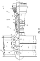
- FIG. 1A schematically illustrates a gas turbine engine 20.
- the gas turbine engine 20 is disclosed herein as a two-spool turbofan that generally incorporates a fan section 22, a compressor section 24, a combustor section 26 and a turbine section 28.
- Alternative engines might include other systems or features.
- the fan section 22 drives air along a bypass flow path B in a bypass duct, while the compressor section 24 drives air along a core flow path C for compression and communication into the combustor section 26 then expansion through the turbine section 28.
- the exemplary engine 20 generally includes a low speed spool 30 and a high speed spool 32 mounted for rotation about an engine central longitudinal axis A relative to an engine static structure 36 via several bearing systems 38. It should be understood that various bearing systems 38 at various locations may alternatively or additionally be provided, and the location of bearing systems 38 may be varied as appropriate to the application.
- the low speed spool 30 generally includes an inner shaft 40 that interconnects a fan 42, a low pressure compressor 44 and a low pressure turbine 46.
- the inner shaft 40 is connected to the fan 42 through a speed change mechanism, which in exemplary gas turbine engine 20 is illustrated as a geared architecture 48 to drive the fan 42 at a lower speed than the low speed spool 30.
- the high speed spool 32 includes an outer shaft 50 that interconnects a high pressure compressor 52 and high pressure turbine 54.
- a combustor 56 is arranged in exemplary gas turbine 20 between the high pressure compressor 52 and the high pressure turbine 54.
- An engine static structure 36 is arranged generally between the high pressure turbine 54 and the low pressure turbine 46.
- the engine static structure 36 further supports bearing systems 38 in the turbine section 28.
- the inner shaft 40 and the outer shaft 50 are concentric and rotate via bearing systems 38 about the engine central longitudinal axis A which is collinear with their longitudinal axes.
- each of the positions of the fan section 22, compressor section 24, combustor section 26, turbine section 28, and fan drive gear system 48 may be varied.
- gear system 48 may be located aft of combustor section 26 or even aft of turbine section 28, and fan section 22 may be positioned forward or aft of the location of gear system 48.
- the engine 20 in one example is a high-bypass geared aircraft engine.
- the engine 20 bypass ratio is greater than about six (6:1), with an example embodiment being greater than about ten (10:1)
- the geared architecture 48 is an epicyclic gear train, such as a planetary gear system or other gear system, with a gear reduction ratio of greater than about 2.3
- the low pressure turbine 46 has a pressure ratio that is greater than about five.
- the engine 20 bypass ratio is greater than about ten (10:1)
- the fan diameter is significantly larger than that of the low pressure compressor 44
- the low pressure turbine 46 has a pressure ratio that is greater than about five (5:1).
- Low pressure turbine 46 pressure ratio is pressure measured prior to inlet of low pressure turbine 46 as related to the pressure at the outlet of the low pressure turbine 46 prior to an exhaust nozzle.
- the geared architecture 48 may be an epicycle gear train, such as a planetary gear system or other gear system, with a gear reduction ratio of greater than about 2.3:1. It should be understood, however, that the above parameters are only exemplary of one embodiment of a geared architecture engine and that the present disclosure is applicable to other gas turbine engines including direct drive turbofans.
- the fan section 22 of the engine 20 is designed for a particular flight condition--typically cruise at about 0.8Mach and about 35,000 feet (10,688 meters).
- 'TSFC' Thrust Specific Fuel Consumption
- Low fan pressure ratio is the pressure ratio across the fan blade alone, without a Fan Exit Guide Vane (“FEGV”) system.
- the low fan pressure ratio as disclosed herein according to one non-limiting embodiment is less than about 1.45.
- Low corrected fan tip speed is the actual fan tip speed in ft/sec divided by an industry standard temperature correction of [(Tram °R)/(518.7 °R)]0.5.
- the "Low corrected fan tip speed” as disclosed herein according to one non-limiting embodiment is less than about 1150 ft/second (350.5 m/sec).
- the gas turbine engine 20 can be coupled to an aircraft, as shown in FIG. 2 , where the aircraft can include multiple instances of the gas turbine engine 20, which can be a hybrid electric turbine engine. Particularly, aircraft can be equipped with two or more hybrid electric turbine engines to provide thrust. Some gas turbine engines, such as hybrid electric gas turbine engines, are equipped with one or more electric machines to convert mechanical energy into electrical energy or vice versa. Two-spool hybrid electric engines can be configured with two electric machines: a first electric machine associated with the low speed spool and a second electric machine associated with the high speed spool. In the event of a failure of one of the electric machines, it may be desirable to distribute electricity from one of the other electric machines to a spool associated with the failed electric machine.
- each engine has times it is adding extra power into its respective high speed spool using its respective high speed spool electric machine. At times, this extra power is obtained from the electric machine of the engine's low speed spool, for example as it extracts power from the low speed spool during an engine deceleration event.
- the low speed spool's electric machine fails, it may be desirable to transfer power from another electric machine (from that engine or from another engine) as supplemental power. For example, if the low speed spool electric machine fails on a first engine, instead of using battery power, excess power from a second engine's low speed spool electric machine can be utilized.
- excess power from the first engine's low speed spool electric machine and/or excess power from another engine's low or high speed spool electric machine can be utilized. This can reduce the size and weight of one or more generators on an aircraft due to reduced power margin built into each unit specifically to handle failure modes.
- electric power from an electric machine of another engine can be used to feed a fan on the failed engine (e.g., the engine that is shut down).
- electric power from another engine can be used for the purpose of spooling up for relight (restart) as an alternative (or assist) to a windmilling relight.
- FIG. 1B is a partial cross-sectional view of a hybrid electric gas turbine engine (also referred to as hybrid electric propulsion system 100) according to one or more embodiments described herein.
- the hybrid electric propulsion system 100 (also referred to as hybrid electric gas turbine engine 100) includes a gas turbine engine 120 operably coupled to an electrical power system 110 as part of a hybrid electric aircraft in accordance with one non-limiting embodiment of the present disclosure.
- the engine 120 has a power source 180 such as a battery, a super capacitor, an ultra-capacitor or an equivalent thereof, which supplies power to a motor 182, which is connected to an engine accessory gearbox 184 that is operably coupled to the high speed spool 32 such that the motor 182, when operated will provide power assist to the high speed spool 32 via the accessory gearbox 184.
- the accessory gearbox will have at least one component (e.g., a gear train or other equivalent device) operably coupled to the high speed spool 32 and the motor 182 such that operation of the motor 182 will rotate the component which in turn will rotate the high speed spool 32.
- the power assist to the high speed spool 32 via the motor 182 will add enough stability to the high pressure compressor in order to allow, for example, re-starting without external power assist which may be provided by an auxiliary power unit (APU).
- APU auxiliary power unit
- the motor 182 may be configured to provide power assist to the high speed spool 32.
- the motor 182 may be part of a different configuration or system configured to only provide power assist to the high speed spool 32 in order to expand an in-flight re-start envelope.
- the motor 182 may be configured to provide power assist to the low speed spool 30.
- the motor 182 may be operatively coupled to the low speed spool 30 via accessory gearbox 184 in order to provide additional thrust to the engine 20.
- the power source 180 and the motor 182 of the power assist system 186 are under the full authority of a full authority digital engine control (FADEC) 156, which controls the power source and the engine.
- the FADEC 156 is an example of a controller that can include a processing system 160, a memory system 162, and an input/output interface 164.
- the processing system 160 can include any type or combination of central processing unit (CPU), including one or more of: a microprocessor, a digital signal processor (DSP), a microcontroller, an application specific integrated circuit (ASIC), a field programmable gate array (FPGA), or the like.
- CPU central processing unit
- DSP digital signal processor
- ASIC application specific integrated circuit
- FPGA field programmable gate array
- the memory system 162 can store data and instructions that are executed by the processing system 160.
- the memory system 162 may include random access memory (RAM), read only memory (ROM), or other electronic, optical, magnetic, or any other computer readable medium onto which is stored data and algorithms in a non-transitory form.
- the input/output interface 164 is configured to collect sensor data from the one or more system sensors and interface with various components and subsystems, such as components of motor drive electronics, rectifier electronics, an energy storage management system, an integrated fuel control unit, actuators, and/or other components of the hybrid electric propulsion system 100.
- the FADEC 156 provides a means for controlling hybrid electric system control effectors 168 based on a power transfer control 166 that is dynamically updated during operation of the hybrid electric propulsion system 100.
- the means for controlling the hybrid electric system control effectors 168 can be otherwise subdivided, distributed, or combined with other control elements.
- the FADEC 156 can also include various operational controls, such as a power transfer control that controls hybrid electric system control effectors.
- the power transfer control 166 can apply control laws and access/update models to determine how to control and transfer power to and from the hybrid electric system control effectors 168. For example, sensed and/or derived parameters related to speed, flow rate, pressure ratios, temperature, thrust, and the like can be used to establish operational schedules and transition limits to maintain efficient operation of the gas turbine engine 120.
- the hybrid electric propulsion system 100 can include a hybrid electric controller 210, which may be integrated into or separate from the FADEC 156.
- the hybrid electric controller 210 is communicatively coupled to the power source 180, the motor 182, and/or any other suitable components. The features and functionality of the hybrid electric controller 210 are described in more detail herein with respect to FIG. 2 .
- An aircraft can selectively power a hybrid electric engine, such as the hybrid electric gas turbine engine 100 of FIG. 1B , by providing electric power from a battery source and/or liquid fuel (jet fuel).
- a hybrid electric engine such as the hybrid electric gas turbine engine 100 of FIG. 1B
- electric power may be more efficient.
- other stages e.g., takeoff, climb
- it may be more efficient to power the engine with liquid fuel.
- electric power may be more efficient, and thus the battery may be utilized to power the hybrid electric engine during taxi.
- One or more embodiments described herein relate to managing battery usage for a hybrid electric engine of an aircraft based on a flight plan and/or data received during the flight. Additionally and/or alternatively, one or more embodiments described herein relate to managing battery charging for a hybrid electric engine of an aircraft based on an energy reserve requirement and an e-taxi energy usage estimation.
- Appropriate management of battery charging and discharging allows for the removal of ram-air turbines (RAT), which are conventionally used to provide power to auxiliary flight systems and charge battery systems. Removing the RAT system improves aircraft performance by removing weight from the aircraft.
- RAT ram-air turbines
- FIG. 2 is a block diagram illustrating a system 200 for managing battery usage for a hybrid electric engine of an aircraft according to one or more embodiments described herein.
- the system 200 includes a hybrid electric controller 210 that is communicatively coupled to an avionics system 220, a battery system 230, an engine controller 240, and electric motor(s) 250.
- an avionics system 220 the battery system 230, the engine controller 240, and the electric motor(s) 250 can be communicatively coupled directly or indirectly together independent of the hybrid electric controller 210.
- the hybrid electric controller 210 can include a processing system (PS) 212 and a memory system (MS) 214.
- the processing system 212 can include any type or combination of central processing unit (CPU), including one or more of: a microprocessor, a digital signal processor (DSP), a microcontroller, an application specific integrated circuit (ASIC), a field programmable gate array (FPGA), or the like.
- CPU central processing unit
- DSP digital signal processor
- ASIC application specific integrated circuit
- FPGA field programmable gate array
- the memory system 214 can store data and instructions that are executed by the processing system 212.
- the memory system 214 may include random access memory (RAM), read only memory (ROM), or other electronic, optical, magnetic, or any other computer readable medium onto which is stored data and algorithms in a non-transitory form.
- the hybrid electric controller 210 receives flight plan data for a flight plan from the avionics system 220.
- the flight plan defines an aircrafts planned route or flight path. Examples of flight plan data include, for example, departure and arrival locations, estimated flight time, planned cruising speed and altitude, etc.
- the hybrid electric controller 210 also receives battery data from the battery system 230.
- the battery data indicates how much electric power (e.g., a number of kilowatt hours of electric power) is available from one or more batteries 232 associated with the battery system 230.
- the hybrid electric controller 210 determines waypoints, as further described herein, for when to apply electric power from the battery system to the electric motor(s) 250 based at least in part on the flight plan data and the battery data.
- the electric motor(s) 250 can include any suitable electric motor, such as the electric motor 182 of FIG. 1B , which can provide power assist to the low speed spool 30 and/or the high speed spool 32 of the gas turbine engine 120.
- the hybrid electric controller also receives data from the engine controller 240, which is an example of the FADEC 156 of FIG. 1B .
- the data represents data about the aircraft, such as avionics information (which can alternatively and/or additionally be received directly from the avionics system 220), engine power settings, etc.
- the hybrid electric controller 210 can also send data and/or commands to the engine controller 240, such as to cause the engine controller 240 to control one or more aspects of the hybrid electric propulsion system 100.
- FIG. 3 is a flow chart illustrating a method for managing battery usage for a hybrid electric engine of an aircraft according to one or more embodiments described herein.
- the method 300 may be performed, for example, by the hybrid electric controller 210 and/or another suitable device.
- the hybrid electric controller 210 receives (such as from the avionics 220) a flight plan comprising flight plan data for a flight of an aircraft.
- the flight plan data can define parameters of the flight, including length of e-taxi out, takeoff, climb, cruise, decent, e-taxi in, target power settings, and the like.
- the target power settings can be derived based on target altitude, calibrated airspeed, climb rate, etc.
- the hybrid electric controller 210 receives battery data from the battery system 230 of the aircraft.
- the battery data indicates a total amount of electric power (e.g., kWh) available from the battery system 230.
- the hybrid electric controller 210 determines waypoints. For example, at block 306, the hybrid electric controller 210 determines waypoints for when to apply electric power from the battery system based at least in part on the flight plan data and the battery data.
- the waypoints define when to use electric power for fuel savings, when to fuel power for battery savings, and/or when to charge the batteries.
- the waypoints can be determined based on a prioritization. For example, the hybrid electric controller 210 prioritizes highest efficiency opportunities to trade off electric power for fuel savings. This can be done by calculating an efficiency ratio (e.g., lbs fuel/ kWh batt). In such an example, a higher efficiency ratio defines waypoints that are higher priority relative to a lower efficiency ratio.
- FIG. 4 depicts an efficiency table 400 according to one or more embodiments described herein.
- the efficiency table 400 includes the following columns: flight phase 402, efficiency ratio 404, engine power setting 406, flight condition 408, and priority.
- electric-taxi (e-taxi) out has an efficiency ratio of 1000 lbs of fuel / 20kWh of electric power. This results in an efficiency ratio of 50 lbs/kWh.
- Efficiency ratios of the other flight phases can be similarly calculated.
- a priority can then be assigned based on the efficiency ratio. For example, e-taxi out and e-taxi in each have relatively high efficiency values compared to the other flight phases and thus they are assigned a higher priority (denoted by the priority values "1" and "2" respectively).
- prioritizing the waypoints can include prioritizing based on a fuel price, based on an amount of fuel expected ,based on an engine power setting, based on a flight condition, based on an emergency condition, etc.
- the hybrid electric controller 210 controls, based at least in part on the waypoints, the electric motor(s) 250 while the flight plan is executed. That is, the hybrid electric controller 210 causes (directly and/or indirectly), the electric motor(s) 250 to engage and/or disengage at certain times during the flight based on the waypoints.
- the hybrid electric controller 210 applies electrical assist (e.g., electric power from the battery system 230 to the electric motor(s) 250) as the flight plan is executed. This can be accomplished using data received during the flight (e.g., avionics information, engine power settings, etc.) to determine where in the flight plan the aircraft currently is.
- the hybrid electric controller 210 updates, while the flight plan is executed, the waypoints based at least in part on data received during the flight.
- the data received during the flight can include data received from the avionics system 220, the engine controller 240, from the battery system 230, etc.
- the hybrid electric controller 210 monitors and responds to the data received during the flight.
- the hybrid electric controller 210 reassess the waypoints based on the data received during the flight (e.g., amount of electric power remaining in the battery system (ex: if there is not enough electric power to perform a full electric-taxi back to the gate upon arrival, use the electric power for climb assist during flight), air traffic control (ATC) data for taxi times (e.g., receiving data about airport taxi times and including that in the calculation), historical taxi data, current and/or historical weather data, etc.).
- ATC air traffic control
- Waypoints can be deleted, added, and/or modified based on the data received during the flight.
- updating the waypoints includes identifying a climb boost opportunity based at least in part on the data received during the flight and the battery data (see, e.g., FIG. 5 ).
- An advantage of one or more embodiments described herein is that substantially all of the electric power stored in the battery system is used during flight/taxi so that the extra weight introduced by the batteries is used as efficiently as possible. Another advantage of one or more embodiments described herein is the ability to use data received during the flight to adjust when and how much electric power to use. Another advantage of one or more embodiments described herein is that maintenance periods can be extended because the gas turbine engine is using battery power for more of the flight. Another advantage of one or more embodiments described herein is improved rotor lifting for smaller aircraft with more transients.
- FIG. 5 depicts an example graph 500 of a flight plan 501 including a climb boost opportunity according to one or more embodiments described herein.
- a climb boost opportunity occurs when excess electric power is determined to exist. That is, more electric power is stored in the battery system 230 than is needed during the flight. Accordingly, this excess electric power can be used during a climb stage of the flight plan.
- waypoints for various stages of the flight plan 501 are determined by the hybrid electric controller 210.
- the waypoints include taxi out waypoint 502, takeoff waypoint 504, climb waypoint 506, climb boost waypoint 508, cruise waypoint 510, descent waypoint 512, and taxi back waypoint 514.
- the waypoints 502, 504, 506, 508, 510, 512, 514 are determined from the flight plan data.
- the hybrid electric controller 210 performs a calculation, as shown in FIG. 5 , to determine an amount of remaining electric power when taking into account the electric power consumed and generated during the various phases of the flight. In this example, 100kWh are initially present in the battery system 230.
- the taxi phases consume 20 kWh and 25kWh, and the climb phase consumes 40 kWh.
- the cruise and descent stages generate 25kWh and 15 kWh respectively. This results in a net excess of 55 kWh that will remain at the end of the flight. Part or all of this excess can be used to provide an extra climb boost, which is represented by the climb boost waypoint 508. That is, excess electric power is provided to the electric motor during the climb phase at the waypoint 508 to provide an extra climb boost. This electric power would otherwise go unused.
- the hybrid electric controller 210 sets waypoints (as shown) based on the flight plan data (e.g., taxi, take off, climb, cruise, decent, and taxi information) and the available 100kWh electric power.
- the hybrid electric engine control system calculates the electric power usage/generation and determines that 55kWh of power remains based on the projected electric power usage/generation.
- the hybrid electric controller 210 identifies an additional opportunity to apply electric power assist via the electric motor(s) 250 to perform an extra climb boost as shown (e.g., waypoint 508). This provides for the electric power stored in the battery system 230 to be used and not wasted.
- FIG. 6 depicts an example graph 600 of a deviated flight plan according to one or more embodiments described herein.
- the hybrid electric controller 210 monitors data received during the flight and can update waypoints (e.g., one or more of waypoints 602, 604, 606, 608, 610, 612, 614) based on the data received during the flight. For example, if more electric power is used or generated during a particular segment of a flight, the other waypoints can be updated accordingly.
- a shorter taxi out shown at waypoint 602 can result in excess electric power available for other stages of the flight. In this example, only 15kWh of electric power was used during taxi out instead of the anticipated 20kWh because of a shorter taxi out.
- the hybrid electric controller 210 confirms extra energy expected in the battery system 230 and re-calculates the remaining waypoints 604, 606, 608, 610, 612, 614.
- FIG. 6 shows the re-calculation of the energy usage/generation estimates revised to account for the shortened taxi out event as compared to the example of FIG. 5 . In this example, because of the shortened taxi out event, 60 kWh remains.
- the hybrid electric controller 210 manages battery charging for a hybrid electric engine of an aircraft based on an energy reserve requirement and an e-taxi energy usage estimation.
- flight plan data from a flight plan is loaded into the hybrid electric controller 210.
- the flight plan data can define parameters of the flight, including length of e-taxi (electric-taxi) out, takeoff, climb, cruise, decent, e-taxi in, etc.
- the location of the aircraft is continuously monitored throughout the flight and a closest safe landing location (e.g., closest airport) is continuously determined throughout the flight.
- An emergency energy reserve requirement is continuously calculated based on the location of the aircraft, a distance to a closest safe landing location (e.g., closest airport), and a projected flight path to the closest safe landing location (e.g., powered flight and/or controlled glide).
- the EERR is the amount of power required in the battery to safely reach the closest safe landing location based on the projected flight path to the closed safest landing location.
- the magnitude of the EERR will change throughout the flight based on where the aircraft is located. For example, once on the ground the EERR may be zero because the aircraft is already safely on the ground. However, if the aircraft is over an ocean, the EERR may be higher because it will take longer to reach the coastline and land safely on the ground.
- a controller such as the hybrid electric controller 210, manages dissipation of electricity from the battery system 230 to ensure that the energy within the battery system 230 is always at or above the EERR throughout the flight.
- a critical use margin is added on top of the EERR to provide the pilot with some flexibility in energy usage during the decent to the closest safe landing location. That is, the critical use margin acts as a buffer on top of the EERR
- the EERR may be a first state of charge to maintain in the battery system 230.
- the controller is also configured to simultaneously manage a second state of charge in the battery system 230 to ensure that the battery system 230 contains enough electrical power to power the hybrid electric engine (e.g., the electric motor(s) 250) for e-taxi in.
- the second state of charge in the battery system 230 may vary based on the length of the e-taxi in both time of day, distance to taxi, duration of taxi, etc.
- the hybrid electric controller 210 causes the battery system 230 to be charged for e-taxi after beginning of cruise, when it is most efficient to charge the battery system 230.
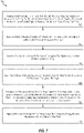
- FIG. 7 depicts a flow diagram of a method 700 for managing battery charging for a hybrid electric engine of an aircraft based on an energy reserve requirement and an e-taxi energy usage estimation according to one or more embodiments described herein.
- the method 700 may be performed, for example, by the hybrid electric controller 210 and/or another suitable device.
- the hybrid electric controller 210 receives flight plan data for a flight of the aircraft.
- the flight plan data includes a distance for an e-taxi for the aircraft and a time period for the e-taxi for the aircraft.
- the hybrid electric engine is powered entirely by the battery during the e-taxi.
- the hybrid electric controller 210 receives battery data about the battery system 230 of the aircraft.
- the battery data includes a battery state of charge throughout the flight.
- the hybrid electric controller 210 detects a plurality of locations of the aircraft throughout the flight using a global positioning satellite (GPS). That is, at various times, the location of the aircraft is determined during the flight.
- GPS global positioning satellite
- the hybrid electric controller 210 determines a closest safe landing location relative to each of the plurality of locations of the aircraft throughout the flight. For example, at a first location, a closest safe landing location (e.g., an airport) is determined. Similarly, at a second location, a closest landing location is determined, which can be the same as or different than the closest safe landing location relative determined for the first location of the aircraft.
- a closest safe landing location e.g., an airport
- the hybrid electric controller 210 determines an emergency energy reserve requirement (EERR) for the closest safe landing location relative to each of the plurality of locations of the aircraft throughout the flight.
- EERR emergency energy reserve requirement
- the EERR is a required state of charge for the battery system 230 to power the aircraft to the closest landing location for a particularly location of the aircraft of the plurality of locations of the aircraft.
- the EERR can change throughout the flight as different of the plurality of locations are used to determine the closest safe landing location.
- the hybrid electric controller 210 maintains the state of charge of the battery above the emergency energy reserve requirement for an entirety of the flight.
- the hybrid electric controller 210 maintains the state of charge of the battery above a state of charge required for an e-taxi. This can be done for a portion of the flight and/or for all of the flight. In the case that it is maintained for a portion of the flight, the portion of the flight is after a start of a cruise portion of the flight.
- the hybrid electric controller 210 utilizes the battery system 230 to power the electric motor(s) 250 and auxiliary equipment of the aircraft until the state of charge drops to the EERR
- the hybrid electric controller 210 causes the battery system 230 to recharge when the state of charge of the battery system 230 is about equal to the EERR
- the hybrid electric controller 210 maintains the state of charge of the battery system 230 above the EERR by a critical use margin for the entirety of the flight. In other examples, the hybrid electric controller 210 maintains the state of charge of the battery system 230 above the EERR by a critical use margin for a predetermined portion of the flight.
- FIG. 8 depicts an example graph 800 of a state of charge of the battery system 230 relative to the time in flight of the aircraft according to one or more embodiments described herein.
- the state of charge 801 in the battery drops after takeoff until it reaches a critical use margin 802 at 803.
- the critical use margin 802 is a threshold amount greater than the EERR 804, which is also shown on the graph 800.
- the battery is charged, as shown by the state of charge 801 in the battery, once the critical use margin 802 is hit at 803, and the state of charge in the battery 801 is maintained until the level for e-taxi is reached 805. This provides for an energy reserve requirement to be satisfied that provides safety and redundancy without requiring conventional RAT systems.
Landscapes
- Engineering & Computer Science (AREA)
- Power Engineering (AREA)
- Aviation & Aerospace Engineering (AREA)
- Physics & Mathematics (AREA)
- General Physics & Mathematics (AREA)
- Sustainable Development (AREA)
- Life Sciences & Earth Sciences (AREA)
- Sustainable Energy (AREA)
- Transportation (AREA)
- Mechanical Engineering (AREA)
- Radar, Positioning & Navigation (AREA)
- Remote Sensing (AREA)
- Charge And Discharge Circuits For Batteries Or The Like (AREA)
- Electric Propulsion And Braking For Vehicles (AREA)
Applications Claiming Priority (1)
| Application Number | Priority Date | Filing Date | Title |
|---|---|---|---|
| US17/345,619 US20220396363A1 (en) | 2021-06-11 | 2021-06-11 | Hybrid electric engine power distribution |
Publications (1)
| Publication Number | Publication Date |
|---|---|
| EP4101686A1 true EP4101686A1 (fr) | 2022-12-14 |
Family
ID=82021113
Family Applications (1)
| Application Number | Title | Priority Date | Filing Date |
|---|---|---|---|
| EP22178725.2A Pending EP4101686A1 (fr) | 2021-06-11 | 2022-06-13 | Distribution de puissance d'un moteur électrique hybride |
Country Status (2)
| Country | Link |
|---|---|
| US (1) | US20220396363A1 (fr) |
| EP (1) | EP4101686A1 (fr) |
Families Citing this family (1)
| Publication number | Priority date | Publication date | Assignee | Title |
|---|---|---|---|---|
| US11867131B2 (en) * | 2021-10-29 | 2024-01-09 | Rtx Corporation | Hybrid electric single engine descent mode activation logic |
Citations (3)
| Publication number | Priority date | Publication date | Assignee | Title |
|---|---|---|---|---|
| CN107211287A (zh) * | 2014-08-29 | 2017-09-26 | 峰鸟航空科技公司 | 使用混合电动飞机实现区域性空中运输网络的系统和方法 |
| JP2019121405A (ja) * | 2019-02-06 | 2019-07-22 | 中国電力株式会社 | 飛行制御システム及び飛行計画作成方法 |
| US20200290742A1 (en) * | 2017-03-19 | 2020-09-17 | Zunum Aero, Inc. | Hybrid-electric aircraft, and methods, apparatus and systems for facilitating same |
Family Cites Families (3)
| Publication number | Priority date | Publication date | Assignee | Title |
|---|---|---|---|---|
| US8209101B2 (en) * | 2006-08-29 | 2012-06-26 | The Boeing Company | Method and system for adaptive power management |
| FR3038750B1 (fr) * | 2015-07-07 | 2018-06-22 | Thales | Procede d'integration d'un nouveau service de navigation dans un systeme avionique embarque a architecture ouverte de type client-serveur, en particulier d'un service de manoeuvre fim |
| US11017678B2 (en) * | 2017-09-22 | 2021-05-25 | Vianair Inc. | Terminal and en-route airspace operations based on dynamic routes |
-
2021
- 2021-06-11 US US17/345,619 patent/US20220396363A1/en active Pending
-
2022
- 2022-06-13 EP EP22178725.2A patent/EP4101686A1/fr active Pending
Patent Citations (3)
| Publication number | Priority date | Publication date | Assignee | Title |
|---|---|---|---|---|
| CN107211287A (zh) * | 2014-08-29 | 2017-09-26 | 峰鸟航空科技公司 | 使用混合电动飞机实现区域性空中运输网络的系统和方法 |
| US20200290742A1 (en) * | 2017-03-19 | 2020-09-17 | Zunum Aero, Inc. | Hybrid-electric aircraft, and methods, apparatus and systems for facilitating same |
| JP2019121405A (ja) * | 2019-02-06 | 2019-07-22 | 中国電力株式会社 | 飛行制御システム及び飛行計画作成方法 |
Also Published As
| Publication number | Publication date |
|---|---|
| US20220396363A1 (en) | 2022-12-15 |
Similar Documents
| Publication | Publication Date | Title |
|---|---|---|
| EP3623203B1 (fr) | Chargement de batterie d'aéronef électrique hybride | |
| EP3789603A1 (fr) | Assistance électrique pour le redémarrage du moteur en vol | |
| CN109110137B (zh) | 用于航空器的推进系统及其操作方法 | |
| US8866318B2 (en) | Method for controlling the generation of electricity applied to an aircraft gas turbine, and device implementing such a method | |
| US20130076120A1 (en) | Aircraft emergency power system | |
| US20120221157A1 (en) | Low pressure spool emergency generator | |
| EP4101686A1 (fr) | Distribution de puissance d'un moteur électrique hybride | |
| EP3895993A1 (fr) | Schéma de charge pour systèmes de propulsion électrique | |
| EP3978728A1 (fr) | Optimisation de la performance d'un aéronef basée sur la surveillance de la performance du moteur | |
| EP3767090B1 (fr) | Contrôle d'opérabilité de compresseur pour une propulsion électrique hybride | |
| US11976589B2 (en) | Gas turbine engine system wear reduction | |
| EP3620634A1 (fr) | Compensation à cycle variable dans un moteur à turbine à gaz | |
| US20220032799A1 (en) | Battery charging for hybrid electric powerplants | |
| EP4102044A2 (fr) | Distribution de la puissance d'un moteur électrique hybride | |
| US11557995B2 (en) | Aircraft engine power-assist start stability control | |
| EP3772579A1 (fr) | Couplage de corps pour moteur à turbine à gaz | |
| JP2019077361A (ja) | 航空機の制御システム、航空機の制御方法、航空機の制御プログラム及び航空機 | |
| US11415065B2 (en) | Material fatigue improvement for hybrid propulsion systems | |
| CN115477018A (zh) | 通过从电动力设备提供机械动力来辅助在高空驾驶旋翼飞行器的方法 | |
| US20230042497A1 (en) | Energy optimization for a hybrid electric engine | |
| US11649763B1 (en) | Rating control architecture and method for hybrid electric engine | |
| EP4175098A1 (fr) | Gestion de défaillance d'un moteur électrique hybride unique lors de la descente | |
| US11781477B2 (en) | Hybrid-electric single engine descent failure management | |
| EP4082915A1 (fr) | Module de mise à jour de système de commande de propulsion hybride | |
| EP4173957A1 (fr) | Gestion de puissance d'une propulsion hybride-électrique en cas de défaillance d'un moteur pendant descente |
Legal Events
| Date | Code | Title | Description |
|---|---|---|---|
| PUAI | Public reference made under article 153(3) epc to a published international application that has entered the european phase |
Free format text: ORIGINAL CODE: 0009012 |
|
| STAA | Information on the status of an ep patent application or granted ep patent |
Free format text: STATUS: THE APPLICATION HAS BEEN PUBLISHED |
|
| AK | Designated contracting states |
Kind code of ref document: A1 Designated state(s): AL AT BE BG CH CY CZ DE DK EE ES FI FR GB GR HR HU IE IS IT LI LT LU LV MC MK MT NL NO PL PT RO RS SE SI SK SM TR |
|
| STAA | Information on the status of an ep patent application or granted ep patent |
Free format text: STATUS: REQUEST FOR EXAMINATION WAS MADE |
|
| 17P | Request for examination filed |
Effective date: 20230614 |
|
| RBV | Designated contracting states (corrected) |
Designated state(s): AL AT BE BG CH CY CZ DE DK EE ES FI FR GB GR HR HU IE IS IT LI LT LU LV MC MK MT NL NO PL PT RO RS SE SI SK SM TR |
|
| RAP3 | Party data changed (applicant data changed or rights of an application transferred) |
Owner name: RTX CORPORATION |