EP4101599B1 - A latch structure - Google Patents
A latch structure Download PDFInfo
- Publication number
- EP4101599B1 EP4101599B1 EP22151585.1A EP22151585A EP4101599B1 EP 4101599 B1 EP4101599 B1 EP 4101599B1 EP 22151585 A EP22151585 A EP 22151585A EP 4101599 B1 EP4101599 B1 EP 4101599B1
- Authority
- EP
- European Patent Office
- Prior art keywords
- latch
- elastic
- catch
- elastic pull
- boss
- Prior art date
- Legal status (The legal status is an assumption and is not a legal conclusion. Google has not performed a legal analysis and makes no representation as to the accuracy of the status listed.)
- Active
Links
Images


Classifications
-
- B—PERFORMING OPERATIONS; TRANSPORTING
- B25—HAND TOOLS; PORTABLE POWER-DRIVEN TOOLS; MANIPULATORS
- B25H—WORKSHOP EQUIPMENT, e.g. FOR MARKING-OUT WORK; STORAGE MEANS FOR WORKSHOPS
- B25H3/00—Storage means or arrangements for workshops facilitating access to, or handling of, work tools or instruments
- B25H3/02—Boxes
Definitions
- the present disclosure relates to a latch structure for connecting a first object with a second object. More specifically, the present disclosure relates to a latch structure that can be used to separably connect and/or lock two objects together.
- US 2020/298392 A1 relates to a latch mechanism configured to secure two bodies together by simply placing one body on top of the other and applying moderate downward pressure to the top body.
- the latch mechanism includes a housing and a latch partially disposed within the housing.
- the latch includes a main body, and a primary hook and an opposing secondary hook both extending from the main body.
- the latch is configured to be rotatable between a first position and a second position. In the first position, the primary hook is not obscured by the housing. In the second position, the primary hook is substantially obscured by the housing.
- the latch mechanism also includes a bias configured to bias the latch toward its first position.
- US 9 725 209 B1 relates to a tool box assembly including first and second tool boxes.
- the second tool box is arranged to removably sit on top of the first tool box.
- at least one of the side walls includes a lip near the top portion.
- the lip has an edge that faces outwards from the at least one of the side walls.
- a latch is arranged to slide along the at least one of the side walls towards and away from the lip.
- the latch includes a catch that includes a catch edge.
- the catch is pivoted about a pivot so that the catch edge is movable towards and away from the at least one of the side walls.
- the latch is biased by a first biasing device configured to provide an urging force to urge the latch towards the top portion.
- the catch is biased by a second biasing device configured to provide an urging force to urge the catch edge towards the at least one of the side walls.
- the purpose of the present disclosure is to provide an improved latch structure.
- the present disclosure discloses a latch structure that can be used on a carrier such as a box or crate.
- the left and right sides of the cover of the carrier are each provided with an elastic pull latch that can be pulled out.
- the elastic pull latch has one sidewall that extends over the upper surface of the latch to form a straight edge above the upper surface.
- the top portion of the straight edge may be referred to as a latch bar and is configured with a latch groove with an inward opening.
- An elastic boss capable of moving vertically is mounted inside the elastic pull latch. When assembled, the upper end of the elastic boss extends out of the upper surface of the latch.
- the left and right sides at the bottom of the carrier are each configured with a catch groove, and a catch is provided on the lower edge of the catch groove.
- the left and right sides of the cover of a carrier are each provided with a chute with an outward opening.
- the elastic pull latch is arranged inside the chute with the side wall of the elastic pull latch being exposed outside the carrier.
- the end of the elastic pull latch that is exposed outside the carrier is also referred to as the outer end of the elastic pull latch.
- the top portion of the straight edge of the side wall is provided with a latch bar, and the latch groove is located on an inner side of the latch bar.
- an upper end of the latch bar has a slope on its inner side.
- the latch bar of the lower carrier is snapped into the catch groove of the upper carrier and the catch of the upper carrier is snapped into the latch groove of the lower carrier.
- a first spring extending horizontally is fitted inside the elastic pull latch.
- a stop piece is connected to the first spring and is mounted on the elastic pull latch. The first spring is retained by the stop piece and a side wall of the elastic pull latch.
- the bottom surface of the elastic pull latch has an elongated through-hole extending horizontally.
- the stop piece is in sliding-fit with the elongated through-hole and can slide along the elongated through-hole.
- the lower end of the stop piece extends outside the elongated through-hole.
- the chute on the upper cover of the carrier has a snap-in hole shaped to match the lower end of the stop piece so that the lower end of the stop piece can be snapped into the snap-in hole.
- the elastic pull latch may be configured with multiple first springs, for example two first springs as shown in Fig. 3 , and multiple corresponding through-holes.
- a second spring extending vertically is mounted inside the elastic pull latch, for example, on the lower inner surface of the elastic pull latch, and is connected to the elastic boss.
- the elastic boss may be situated on top of the second spring.
- the upper surface of the elastic pull latch has an opening allowing the top of the elastic boss to pass through.
- the elastic pull latch is internally provided with an accommodating slot for housing the elastic boss.
- the lower end of the elastic boss may include a spring recess with a downward opening for housing the second spring.
- the bottom side of the catch of the upper carrier of two adjacent carriers is in contact with and presses onto the top of the elastic boss of the elastic pull latch of the lower carrier.
- the elastic boss of the elastic pull latch moves outwards.
- the catch blocks the elastic boss so that the elastic boss is held on the outer side of the catch and the latch is prevented from retracting inwards.
- the carrier may be a box, a trunk, a crate, or a pallet.
- each elastic pull latch can be pulled out using one hand and will remain in a pulled-out state without retracting so that other elastic pull latches can be released one by one.
- stacked up carriers can be released and unlatched "single-handedly," literally speaking, making the latch more convenient to use.
- the present disclosure discloses a specific latch structure, comprising a carrier, wherein left and right sides of an upper end of the carrier are each provided with an elastic pull latch that can be pulled out; an upper end of the elastic pull latch has a catch groove with an inward opening; an elastic boss capable of moving vertically is mounted in the elastic pull latch; an upper end of the elastic boss extends out of the upper end of the carrier; left and right sides of a lower end of the carrier are each provided with a latch groove, and a catch is provided in a lower end of the latch groove; when at least two carriers of the same structure are stacked one above another, the catch at the lower end of one of two adjacent carriers is snapped into the catch groove of the elastic pull latch at the upper end of the other carrier, and a bottom portion of the catch depresses the elastic boss; and after the elastic pull latch of the lower carrier of the two adjacent carriers is pulled out, the elastic boss is retained on an outer side of the catch.
- left and right sides of the upper cover are each provided with a chute with an outward opening; the elastic pull latch is arranged in the chute; and an outer end of the elastic pull latch is exposed outside the carrier.
- a first spring extending horizontally is mounted in the elastic pull latch; a stop piece is further mounted in the elastic pull latch; the first spring is retained between the stop piece and an inner wall of the elastic pull latch; the bottom portion of the elastic pull latch has an elongated through-hole extending horizontally; the stop piece is in sliding fit with the elongated through-hole; a lower end of the stop piece penetrates through the elongated through-hole; the chute has a snap-in hole correspondingly shaped to the lower end of the stop piece; and the lower end of the stop piece is snapped into the snap-in hole.
- the elastic pull latch is internally provided with an accommodating slot; the elastic boss is arranged in the accommodating slot; the lower end of the elastic boss has a spring recess with a downward opening; and the second spring is arranged in the spring recess.
- the carrier is a box.
- the present disclosure discloses a latch structure that can be used on a carrier such as a trunk or a box. These terms may be used interchangeable herein and are not intended to limit the manner of how the disclosed device is used or the scope of the disclosure.
- the left and right sides of the cover 2 of the carrier are each provided with an elastic pull latch 3 that can extend outwards when pulled.
- the top of the elastic pull latch 3 is a latch bar 321, which has a latch groove 3211 with an inward opening.
- An elastic boss 33 capable of moving vertically is mounted in the elastic pull latch 3.
- the top of the elastic boss 33 extends out of the upper surface of the carrier.
- the left and right sides of the bottom of the carrier are each provided with a catch groove 11.
- a catch 12 resembling a rectangular block or a ridge is provided on the lower edge of the catch groove 11.
- the catch 12 on the bottom of the upper carrier is snapped into the latch groove 3211 of the elastic pull latch 3 located on the cover 2 of the lower carrier.
- the bottom side of the catch 12 depresses the elastic boss 33. See Fig. 6 and Fig. 7 .
- the elastic boss 33 is held on the outer side of the catch 12 because the catch 12 blocks the elastic boss 33 preventing the pull latch 3 from moving inwards.
- the left and right sides of the upper cover 2 of a carrier are each provided with a chute 21 with an outward opening.
- the elastic pull latch 3 is arranged inside the chute 21 on the cover 2. The outer end of the elastic pull latch 3 remains outside the chute 21.
- a top portion of the outer end of the elastic pull latch 3 includes a latch bar 321 that sticks outside the pull latch cover 32.
- the latch groove 3211 is located on the inner side of the latch bar 321.
- the upper end of the latch bar 321 has a slope 3212 on the inner side, the side that faces the interior of the pull latch cover 32.
- the slope 3212 matches the slope of the catch groove 11 as shown in Fig. 7 .
- the elastic pull latch 3 is pushed outwards to snap the catch 12 into the latch groove 3211 of the pull latch and snap the latch bar 312 into the catch groove 11.
- first springs 34 extending horizontally are mounted in the elastic pull latch 3.
- Two stop pieces 35 are mounted in the elastic pull latch 3.
- Each of the first springs 34 is retained between a stop piece 35 and an inner wall of the elastic pull latch 3.
- the bottom portion of the elastic pull latch 3 has two elongated through-holes 311 extending horizontally.
- the stop pieces 35 are in sliding-fit with the elongated through-holes 311 and can slide through the through-holes 311.
- the lower end of each stop piece 35 passes through and comes out of the elongated through-holes 311.
- the chute 21 on the upper cover 2 of the box is internally provided with a snap-in hole 211 shaped to match the lower end of the stop piece 35.
- the lower end of the stop piece 35 can be snapped into the snap-in hole 211.
- a second spring 36 extending vertically is mounted in the elastic pull latch 3 and the elastic boss 33 is situated on the second spring 36.
- the upper surface of the elastic pull latch 3 has an opening 322, allowing the top of the elastic boss 33 to pass through.
- the elastic pull latch 3 is internally provided with an accommodating slot 323.
- the elastic boss 33 is arranged in the accommodating slot 323.
- the lower end of the elastic boss 33 includes a spring recess 331 with a downward opening.
- the second spring 36 is housed in the spring recess 331.
- the elastic pull latch 3 includes a base 31 and a pull latch cover 32 on top of the base 31.
- the accommodating slot 323 (see Fig. 7 ), the opening 322, and the latch bar 321 are arranged in or on the pull latch cover 32.
- the elongated through-hole or through-holes 311 are formed in the base 31.
- the catch 12 of an upper box can directly snap into the latch groove 3211 of a lower box, as shown in Fig. 7 and Fig. 8 .
- the elastic pull latches 3 can be released one by one, instead of being released one pair at a time by both hands. In this way, the stacked boxes can be separated and removed more conveniently.
- the elastic boss 33 in the elastic pull latches 3 of the lower box is no longer held by the catch 12.
- the elastic pull latch 3 of the lower box is automatically reset by the compressed first springs 34.
- a latch structure comprising an elastic pull latch.
- the top of the elastic pull latch includes a latch bar configured with a latch groove.
- the elastic pull latch also includes an elastic boss that moves in and out of the latch cover of the pull latch.
- On both sides of a box an elastic pull latch is provided at the top and a catch groove having a catch affixed to the lower edge is provided at the bottom.
Landscapes
- Engineering & Computer Science (AREA)
- Mechanical Engineering (AREA)
- Stackable Containers (AREA)
Description
- The present disclosure relates to a latch structure for connecting a first object with a second object. More specifically, the present disclosure relates to a latch structure that can be used to separably connect and/or lock two objects together.
-
US 2020/298392 A1 relates to a latch mechanism configured to secure two bodies together by simply placing one body on top of the other and applying moderate downward pressure to the top body. The latch mechanism includes a housing and a latch partially disposed within the housing. The latch includes a main body, and a primary hook and an opposing secondary hook both extending from the main body. The latch is configured to be rotatable between a first position and a second position. In the first position, the primary hook is not obscured by the housing. In the second position, the primary hook is substantially obscured by the housing. The latch mechanism also includes a bias configured to bias the latch toward its first position. -
US 9 725 209 B1 - When objects such as boxes, crates, or pallets that are stacked one above another, adjacent stacked objects can be joined together by a latch to improve the stability of the stacked-up objects. However, when separating the stacked items, the latch structures known in the prior art are inconvenient to unlatch. Usually, the uppermost item must be unlatched from the adjacent item immediately below it by two hands, before it can be released and removed from the stack. This is often inconvenient.
- Accordingly, in view of the above-mentioned defects of prior art latches, the purpose of the present disclosure is to provide an improved latch structure.
- This object is solved with a latch structure according to
Claim 1. Particular advantageous embodiments are specified in the dependent claims. - The present disclosure discloses a latch structure that can be used on a carrier such as a box or crate. The left and right sides of the cover of the carrier are each provided with an elastic pull latch that can be pulled out. The elastic pull latch has one sidewall that extends over the upper surface of the latch to form a straight edge above the upper surface. The top portion of the straight edge may be referred to as a latch bar and is configured with a latch groove with an inward opening. An elastic boss capable of moving vertically is mounted inside the elastic pull latch. When assembled, the upper end of the elastic boss extends out of the upper surface of the latch. The left and right sides at the bottom of the carrier are each configured with a catch groove, and a catch is provided on the lower edge of the catch groove.
- When multiple carriers of the same or similar structures are stacked one above another, a catch at the bottom of the upper carrier of two adjacent carriers is snapped into the latch groove of an elastic pull latch located on the cover of the lower carrier. The bottom side of the catch of the upper carrier touches and depresses the elastic boss of the elastic pull latch of the lower carrier. After the elastic pull latch of the lower carrier is pulled out, the elastic boss rises above and extends out of the upper surface of the latch so it becomes blocked by the catch. As such, the elastic pull latch is held on the outer side of the catch. The elastic pull latch remains in a pulled-out position and is prevented from moving inwards.
- In some embodiments, the left and right sides of the cover of a carrier are each provided with a chute with an outward opening. The elastic pull latch is arranged inside the chute with the side wall of the elastic pull latch being exposed outside the carrier. The end of the elastic pull latch that is exposed outside the carrier is also referred to as the outer end of the elastic pull latch.
- In some embodiments, the top portion of the straight edge of the side wall is provided with a latch bar, and the latch groove is located on an inner side of the latch bar.
- In some embodiments, an upper end of the latch bar has a slope on its inner side.
- In some embodiments, when two carriers of the same structure are stacked one above another, on each side of the stacked-up carriers the latch bar of the lower carrier is snapped into the catch groove of the upper carrier and the catch of the upper carrier is snapped into the latch groove of the lower carrier.
- In some embodiments, a first spring extending horizontally is fitted inside the elastic pull latch. A stop piece is connected to the first spring and is mounted on the elastic pull latch. The first spring is retained by the stop piece and a side wall of the elastic pull latch. The bottom surface of the elastic pull latch has an elongated through-hole extending horizontally. The stop piece is in sliding-fit with the elongated through-hole and can slide along the elongated through-hole. The lower end of the stop piece extends outside the elongated through-hole. The chute on the upper cover of the carrier has a snap-in hole shaped to match the lower end of the stop piece so that the lower end of the stop piece can be snapped into the snap-in hole. In some embodiments, the elastic pull latch may be configured with multiple first springs, for example two first springs as shown in
Fig. 3 , and multiple corresponding through-holes. - In some embodiments, a second spring extending vertically is mounted inside the elastic pull latch, for example, on the lower inner surface of the elastic pull latch, and is connected to the elastic boss. The elastic boss may be situated on top of the second spring. The upper surface of the elastic pull latch has an opening allowing the top of the elastic boss to pass through.
- In some embodiments, the elastic pull latch is internally provided with an accommodating slot for housing the elastic boss. The lower end of the elastic boss may include a spring recess with a downward opening for housing the second spring.
- In some embodiments, the bottom side of the catch of the upper carrier of two adjacent carriers is in contact with and presses onto the top of the elastic boss of the elastic pull latch of the lower carrier. When the elastic pull latch of the lower carrier is pulled outwards, the elastic boss of the elastic pull latch moves outwards. After the elastic boss moves away from the catch and moves upwards from underneath the bottom of the catch, the catch blocks the elastic boss so that the elastic boss is held on the outer side of the catch and the latch is prevented from retracting inwards.
- In some embodiments, the carrier may be a box, a trunk, a crate, or a pallet.
- One of the advantages of the latch structure disclosed in the present disclosure is that, when stacked carriers need to be separated, each elastic pull latch can be pulled out using one hand and will remain in a pulled-out state without retracting so that other elastic pull latches can be released one by one. In this way, stacked up carriers can be released and unlatched "single-handedly," literally speaking, making the latch more convenient to use.
- The present disclosure discloses a specific latch structure, comprising a carrier, wherein left and right sides of an upper end of the carrier are each provided with an elastic pull latch that can be pulled out; an upper end of the elastic pull latch has a catch groove with an inward opening; an elastic boss capable of moving vertically is mounted in the elastic pull latch; an upper end of the elastic boss extends out of the upper end of the carrier; left and right sides of a lower end of the carrier are each provided with a latch groove, and a catch is provided in a lower end of the latch groove; when at least two carriers of the same structure are stacked one above another, the catch at the lower end of one of two adjacent carriers is snapped into the catch groove of the elastic pull latch at the upper end of the other carrier, and a bottom portion of the catch depresses the elastic boss; and after the elastic pull latch of the lower carrier of the two adjacent carriers is pulled out, the elastic boss is retained on an outer side of the catch.
- In an embodiment of said specific latch structure, left and right sides of the upper cover are each provided with a chute with an outward opening; the elastic pull latch is arranged in the chute; and an outer end of the elastic pull latch is exposed outside the carrier.
- In an embodiment of said specific latch structure of paragraph [0017], wherein a top portion of the outer end of the elastic pull latch is provided with a latch bar, and the catch groove is located on an inner side of the latch bar.
- In an embodiment of said specific latch structure of paragraph [0018], whrein an upper end of the latch bar has a slope on an inner side.
- In an embodiment of said specific latch structure of paragraph [0018], when at least two carriers of the same structure are stacked one above another, the latch bar of one of adjacent carriers is snapped into the latch groove of the other carrier.
- In an embodiment of said specific latch structure of paragraph [0017], a first spring extending horizontally is mounted in the elastic pull latch; a stop piece is further mounted in the elastic pull latch; the first spring is retained between the stop piece and an inner wall of the elastic pull latch; the bottom portion of the elastic pull latch has an elongated through-hole extending horizontally; the stop piece is in sliding fit with the elongated through-hole; a lower end of the stop piece penetrates through the elongated through-hole; the chute has a snap-in hole correspondingly shaped to the lower end of the stop piece; and the lower end of the stop piece is snapped into the snap-in hole.
- In an embodiment of said specific latch structure of paragraph [0016], wherein a second spring extending vertically is mounted in the elastic pull latch; the elastic boss is disposed over the second spring; and the upper end of the elastic pull latch has a penetrating hole allowing the upper end of the elastic boss to penetrate through.
- In an embodiment of said specific latch structure of paragraph [0022], the elastic pull latch is internally provided with an accommodating slot; the elastic boss is arranged in the accommodating slot; the lower end of the elastic boss has a spring recess with a downward opening; and the second spring is arranged in the spring recess.
- In an embodiment of said specific latch structure of paragraph [0016], wherein a bottom portion of the catch of one of two adjacent carriers is in contact with a top portion of the elastic boss of the other carrier; when the elastic pull latch is pulled outwards, the elastic boss moves outwards; and after the top portion of the elastic boss is separated from the bottom portion of the catch, the elastic boss moves upwards, so that the elastic boss is retained on the outer side of the catch.
- In an embodiment of said specific latch structure of any one of paragraphs [0016] - [0024], the carrier is a box.
- These and other features of the present disclosure will become readily apparent upon further review of the following specification and drawings. In the drawings, like reference numerals designate corresponding parts throughout the views. Moreover, components in the drawings are not necessarily drawn to scale, the emphasis instead being placed upon clearly illustrating the principles of the present disclosure.
-
Fig. 1 is a schematic diagram of a carrier configured with a latch of the present disclosure; -
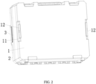
Fig. 2 is a schematic diagram showing the bottom of a carrier provided with a latch of the present disclosure; -
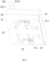
Fig. 3 is a schematic diagram of an overall structure of an elastic pull latch of the present disclosure; -
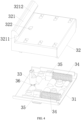
Fig. 4 is a schematic diagram of an internal structure of a pull latch of the present disclosure; -
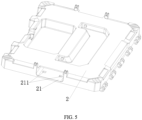
Fig. 5 is a schematic diagram of a carrier cover configured with a pull latch of the present disclosure; -
Fig. 6 is a schematic diagram showing two boxes joined together by two latches of the present disclosure; -
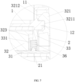
Fig. 7 is an enlarged view of region A inFig. 6 ; -
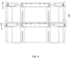
Fig. 8 is a schematic diagram showing two boxes unlatched from each other when the latches are released; and -
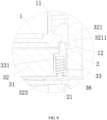
Fig. 9 is an enlarged view of region B inFig. 8 . - Embodiments of the disclosure are described more fully hereinafter with reference to the accompanying drawings, in which preferred embodiments of the disclosure are shown. The various embodiments of the disclosure may, however, be embodied in many different forms and should not be construed as limited to the embodiments set forth herein. Rather, these embodiments are provided so that this disclosure will be thorough and complete, and will fully convey the scope of the disclosure to those skilled in the art.
- In referring to
Fig. 1 - Fig. 9 , the present disclosure discloses a latch structure that can be used on a carrier such as a trunk or a box. These terms may be used interchangeable herein and are not intended to limit the manner of how the disclosed device is used or the scope of the disclosure. The left and right sides of thecover 2 of the carrier are each provided with anelastic pull latch 3 that can extend outwards when pulled. The top of theelastic pull latch 3 is alatch bar 321, which has alatch groove 3211 with an inward opening. Anelastic boss 33 capable of moving vertically is mounted in theelastic pull latch 3. The top of theelastic boss 33 extends out of the upper surface of the carrier. The left and right sides of the bottom of the carrier are each provided with acatch groove 11. Acatch 12 resembling a rectangular block or a ridge is provided on the lower edge of thecatch groove 11. - When at least two carriers of the same or similar structure are stacked one above another, the
catch 12 at the bottom of an upper carrier is snapped into thelatch groove 3211 of theelastic pull latch 3 on theupper cover 2 of the lower carrier, and the bottom surface of thecatch 12 on the upper carrier touches and depresses theelastic boss 33 of thepull latch 3 on the lower carrier. After theelastic pull latch 3 of the lower carrier is pulled out, theelastic boss 33 moves upwards and is then blocked by thecatch 12. Thepull latch 3 is being prevented from retracting inwards and is held on the outer side of thecatch 12. SeeFig. 8 andFig. 9 for reference. - When one carrier is stacked above another carrier, the
catch 12 on the bottom of the upper carrier is snapped into thelatch groove 3211 of theelastic pull latch 3 located on thecover 2 of the lower carrier. The bottom side of thecatch 12 depresses theelastic boss 33. SeeFig. 6 andFig. 7 . After theelastic pull latch 3 of the lower carrier is pulled out, theelastic boss 33 is held on the outer side of thecatch 12 because thecatch 12 blocks theelastic boss 33 preventing thepull latch 3 from moving inwards. - As shown in
Fig. 1 andFig. 5 , the left and right sides of theupper cover 2 of a carrier are each provided with achute 21 with an outward opening. Theelastic pull latch 3 is arranged inside thechute 21 on thecover 2. The outer end of theelastic pull latch 3 remains outside thechute 21. - As shown in
Fig. 3 , a top portion of the outer end of theelastic pull latch 3 includes alatch bar 321 that sticks outside thepull latch cover 32. Thelatch groove 3211 is located on the inner side of thelatch bar 321. The upper end of thelatch bar 321 has aslope 3212 on the inner side, the side that faces the interior of thepull latch cover 32. In some embodiments, theslope 3212 matches the slope of thecatch groove 11 as shown inFig. 7 . When one box is stacked above another box, thelatch bar 321 of the lower box is snapped into thecatch groove 11 of the upper box, as shown inFig. 7 . Because the upper end of thelatch bar 321 is shaped into aslope 3212, when thecatch 12 of the upper box is in contact with theslope 3212 of thelatch bar 321 of the lower box, theelastic pull latch 3 is pushed outwards to snap thecatch 12 into thelatch groove 3211 of the pull latch and snap the latch bar 312 into thecatch groove 11. - As shown in
Figs. 3-5 , twofirst springs 34 extending horizontally are mounted in theelastic pull latch 3. Twostop pieces 35 are mounted in theelastic pull latch 3. Each of thefirst springs 34 is retained between astop piece 35 and an inner wall of theelastic pull latch 3. The bottom portion of theelastic pull latch 3 has two elongated through-holes 311 extending horizontally. Thestop pieces 35 are in sliding-fit with the elongated through-holes 311 and can slide through the through-holes 311. The lower end of eachstop piece 35 passes through and comes out of the elongated through-holes 311. Thechute 21 on theupper cover 2 of the box is internally provided with a snap-inhole 211 shaped to match the lower end of thestop piece 35. The lower end of thestop piece 35 can be snapped into the snap-inhole 211. When theelastic pull latch 3 is pulled outwards, thestop piece 35 stays inside the snap-inhole 211 and thefirst spring 34 becomes compressed. - As shown in
Fig. 4 , asecond spring 36 extending vertically is mounted in theelastic pull latch 3 and theelastic boss 33 is situated on thesecond spring 36. The upper surface of theelastic pull latch 3 has anopening 322, allowing the top of theelastic boss 33 to pass through. In the embodiments shown inFigs. 7 and9 , theelastic pull latch 3 is internally provided with anaccommodating slot 323. Theelastic boss 33 is arranged in theaccommodating slot 323. The lower end of theelastic boss 33 includes aspring recess 331 with a downward opening. Thesecond spring 36 is housed in thespring recess 331. - In
Fig. 6 andFig. 7 , two boxes are stacked one on top of the other. The boxes are securely latched together using two elastic pull latches 3. When in a locked position, the bottom of thecatch 12 of the upper box is in contact with the top of theelastic boss 33 of the lower box, and thesecond spring 36 underneath theelastic boss 33 is compressed. When the latch is released as shown inFig. 8 andFig. 9 , theelastic pull latch 3 is pulled outwards and theelastic boss 33 moves outwards. After theelastic boss 33 moves away from thecatch 12, theelastic boss 33 is pushed upward by the compressedsecond spring 36. SeeFig. 9 . When in a released position, theelastic boss 33 is held on the outer side of thecatch 12 and theelastic pull latch 3 remains in a pulled-out state. - As shown in
Figs. 3 and4 , theelastic pull latch 3 includes abase 31 and apull latch cover 32 on top of thebase 31. The accommodating slot 323 (seeFig. 7 ), theopening 322, and thelatch bar 321 are arranged in or on thepull latch cover 32. The elongated through-hole or through-holes 311 are formed in thebase 31. - In some embodiments, when a plurality of boxes are stacked one above another, the
catch 12 of an upper box can directly snap into thelatch groove 3211 of a lower box, as shown inFig. 7 andFig. 8 . When the stacked boxes need to be separated, the elastic pull latches 3 can be released one by one, instead of being released one pair at a time by both hands. In this way, the stacked boxes can be separated and removed more conveniently. After the upper box is removed, theelastic boss 33 in the elastic pull latches 3 of the lower box is no longer held by thecatch 12. Theelastic pull latch 3 of the lower box is automatically reset by the compressed first springs 34. - In sum, a latch structure comprising an elastic pull latch is disclosed. The top of the elastic pull latch includes a latch bar configured with a latch groove. The elastic pull latch also includes an elastic boss that moves in and out of the latch cover of the pull latch. On both sides of a box, an elastic pull latch is provided at the top and a catch groove having a catch affixed to the lower edge is provided at the bottom. When two boxes are stacked together, the catch in the catch groove of the upper box is snapped into the latch groove of the elastic pull latch of the lower box to securely connect the two boxes. When the latch is released, the catch of the upper box blocks the elastic boss of the latch of the lower box to prevent the latch from retracting inwards.
Claims (10)
- A latch structure for connecting a first object with a second object; comprisingan elastic pull latch (3), wherein the elastic pull latch (3) includes a latch cover (32), a base (31), characterized in that the elastic pull latch (3) further includes an elastic boss (33) mounted on the base (31) and capable of moving vertically when mounted in the elastic pull latch (3), and a latch bar (321) that extends above the latch cover (32) and is configured with a latch groove (3211); anda catch (12) that is affixed inside a catch groove (11);wherein the elastic pull latch (3) is installed on the first object and the catch groove (11) is provided on the second object with the catch (12) affixed to the lower edge of the catch groove (11);wherein the latch cover (32) is configured with an opening to accommodate the top of the elastic boss (33), and the top of the elastic boss (33) is configured to move through the opening of the latch cover (32);wherein when the catch (12) is snapped into the latch groove (11) of the elastic pull latch (3) and the top of the elastic boss (33) is pressed into the opening by the catch (12), the latch (3) is fastened to securely connect the first object and the second object; andwherein when the latch (3) is released, the elastic boss (33) moves out of the opening and is blocked by the catch (12) to prevent the elastic pull latch from retracting inwards.
- A latch structure as defined in claim 1, wherein when the latch (3) is fastened, the latch bar (321) is snapped into the catch groove (11).
- A latch structure as defined in claim 2, wherein the elastic pull latch (3) is arranged inside a chute (21) on the first object; and an outer end of the elastic pull latch (3) is exposed outside the chute (21) on the first object.
- A latch structure as defined in claim 3, wherein the latch bar (321) is located on a top portion of the outer end of the elastic pull latch (3), and the latch groove (3211) is located on an inner side of the latch bar (321).
- A latch structure as defined in claim 4, wherein an upper end of the latch bar (321) has a slope (3212) shape on an inner side.
- A latch structure as defined in claim 3, wherein one or more first springs (34) extending horizontally are mounted in the elastic pull latch (3), a stop piece (35) is attached to each of the one or more first springs (34) and is further mounted in the elastic pull latch (3), each of the first springs (34) is retained between the stop piece (35) and an inner wall of the elastic pull latch (3);wherein the base (31) of the elastic pull latch (3) is configured with one or more elongated through-holes (311) extending horizontally, each stop piece (35) is in sliding fit with each elongated through-hole (311) with a lower end of each stop piece (35) passing through the elongated through-hole (311); andwherein the chute (21) has one or more snap-in holes (211), each shaped to match the lower end of the stop piece (35) to allow the lower end of the stop piece (35) to be snapped into the snap-in hole (211).
- A latch structure as defined in claim 1, wherein a second spring (36) extending vertically is mounted in the elastic pull latch (3); wherein the elastic boss (33) is situated on the second spring (36); and wherein the opening on the latch cover (32) of the elastic pull latch (3) allows the top of the elastic boss (33) to pass through.
- A latch structure as defined in claim 7, wherein the elastic pull latch (3) is internally provided with an accommodating slot (323) for housing the elastic boss (33); wherein the lower end of the elastic boss (33) has a spring recess (331) with a downward opening (322); and wherein the second spring (36) is arranged in the spring recess (331).
- A latch structure as defined in claim 1, wherein when the latch (3) is fastened, a bottom portion of the catch (12) is in contact with a top portion of the elastic boss (33); wherein when the elastic pull latch (3) is pulled outwards, the elastic boss (33) moves outwards; and wherein after the elastic boss (33) moves away from the bottom portion of the catch (12), the elastic boss (33) moves upwards and the elastic boss (33) is held by the catch on the outer side of the catch (12).
- A latch structure as defined in any one of the preceding claims, wherein the first object and the second object are boxes (1) stacked on top of each other.
Applications Claiming Priority (2)
| Application Number | Priority Date | Filing Date | Title |
|---|---|---|---|
| CN202121315213.5U CN214904396U (en) | 2021-06-11 | 2021-06-11 | Lock catch structure |
| US17/530,216 US11788329B2 (en) | 2021-06-11 | 2021-11-18 | Latch structure |
Publications (2)
| Publication Number | Publication Date |
|---|---|
| EP4101599A1 EP4101599A1 (en) | 2022-12-14 |
| EP4101599B1 true EP4101599B1 (en) | 2024-07-17 |
Family
ID=80112344
Family Applications (1)
| Application Number | Title | Priority Date | Filing Date |
|---|---|---|---|
| EP22151585.1A Active EP4101599B1 (en) | 2021-06-11 | 2022-01-14 | A latch structure |
Country Status (2)
| Country | Link |
|---|---|
| EP (1) | EP4101599B1 (en) |
| PL (1) | PL4101599T3 (en) |
Families Citing this family (1)
| Publication number | Priority date | Publication date | Assignee | Title |
|---|---|---|---|---|
| US20240351744A1 (en) * | 2021-07-09 | 2024-10-24 | G.T. Line - S.R.L. | Set of transportable containers |
Family Cites Families (5)
| Publication number | Priority date | Publication date | Assignee | Title |
|---|---|---|---|---|
| US8297464B2 (en) * | 2007-06-13 | 2012-10-30 | Jean-Pierre Grenier | Carrying case with locking latch mechanism |
| DE202015005752U1 (en) * | 2015-08-18 | 2016-11-21 | Plaston Ag | Stackable case with coupling connection and fuse |
| US11267119B2 (en) * | 2015-12-14 | 2022-03-08 | Milwaukee Electric Tool Corporation | Storage device system |
| US9725209B1 (en) * | 2016-09-14 | 2017-08-08 | Tefenplast Ltd. | Stackable tool box assembly |
| US11642777B2 (en) * | 2018-07-18 | 2023-05-09 | The Stanley Works Israel Ltd. | Stacking latch mechanism |
-
2022
- 2022-01-14 PL PL22151585.1T patent/PL4101599T3/en unknown
- 2022-01-14 EP EP22151585.1A patent/EP4101599B1/en active Active
Also Published As
| Publication number | Publication date |
|---|---|
| PL4101599T3 (en) | 2024-12-16 |
| EP4101599A1 (en) | 2022-12-14 |
Similar Documents
| Publication | Publication Date | Title |
|---|---|---|
| US11788329B2 (en) | Latch structure | |
| US4076117A (en) | Safety match box | |
| US8714355B2 (en) | Integrated storage system with locking containers | |
| CN103754516B (en) | Container lid lockout mechanism and container | |
| CN1735540B (en) | container with lid | |
| US5390811A (en) | Wafer basket for containing semiconductor wafers | |
| US3942630A (en) | Sliding cover safety package | |
| US4340140A (en) | Package construction | |
| US5593031A (en) | Disc accommodation device including movable disc holder | |
| US20190039233A1 (en) | Toolbox | |
| EP4101599A1 (en) | A latch structure | |
| JP2012041053A (en) | Box-shaped vessel | |
| US4377303A (en) | Closure latch mechanism improvements | |
| AU2021290389A1 (en) | A latch structure | |
| US12203301B2 (en) | Lock lever and opening/closing device | |
| JP3703626B2 (en) | Storage case | |
| CN218170367U (en) | Multi-layer tool box | |
| WO2009019217A1 (en) | Container for smoking articles | |
| JPH049335Y2 (en) | ||
| CN214904396U (en) | Lock catch structure | |
| KR200337212Y1 (en) | Box | |
| CN116729770B (en) | Connection structure, storage tank and storage tank subassembly of module | |
| US20210061528A1 (en) | Box Assembly with Safeguard Locking Function | |
| KR200440604Y1 (en) | Wafer cassette box | |
| JPS6025218Y2 (en) | Surgical suture needle storage case |
Legal Events
| Date | Code | Title | Description |
|---|---|---|---|
| PUAI | Public reference made under article 153(3) epc to a published international application that has entered the european phase |
Free format text: ORIGINAL CODE: 0009012 |
|
| STAA | Information on the status of an ep patent application or granted ep patent |
Free format text: STATUS: THE APPLICATION HAS BEEN PUBLISHED |
|
| AK | Designated contracting states |
Kind code of ref document: A1 Designated state(s): AL AT BE BG CH CY CZ DE DK EE ES FI FR GB GR HR HU IE IS IT LI LT LU LV MC MK MT NL NO PL PT RO RS SE SI SK SM TR |
|
| STAA | Information on the status of an ep patent application or granted ep patent |
Free format text: STATUS: REQUEST FOR EXAMINATION WAS MADE |
|
| 17P | Request for examination filed |
Effective date: 20230120 |
|
| RBV | Designated contracting states (corrected) |
Designated state(s): AL AT BE BG CH CY CZ DE DK EE ES FI FR GB GR HR HU IE IS IT LI LT LU LV MC MK MT NL NO PL PT RO RS SE SI SK SM TR |
|
| GRAP | Despatch of communication of intention to grant a patent |
Free format text: ORIGINAL CODE: EPIDOSNIGR1 |
|
| STAA | Information on the status of an ep patent application or granted ep patent |
Free format text: STATUS: GRANT OF PATENT IS INTENDED |
|
| RIC1 | Information provided on ipc code assigned before grant |
Ipc: B25H 3/02 20060101AFI20231101BHEP |
|
| INTG | Intention to grant announced |
Effective date: 20231121 |
|
| GRAJ | Information related to disapproval of communication of intention to grant by the applicant or resumption of examination proceedings by the epo deleted |
Free format text: ORIGINAL CODE: EPIDOSDIGR1 |
|
| STAA | Information on the status of an ep patent application or granted ep patent |
Free format text: STATUS: REQUEST FOR EXAMINATION WAS MADE |
|
| INTC | Intention to grant announced (deleted) | ||
| GRAP | Despatch of communication of intention to grant a patent |
Free format text: ORIGINAL CODE: EPIDOSNIGR1 |
|
| STAA | Information on the status of an ep patent application or granted ep patent |
Free format text: STATUS: GRANT OF PATENT IS INTENDED |
|
| INTG | Intention to grant announced |
Effective date: 20240322 |
|
| GRAS | Grant fee paid |
Free format text: ORIGINAL CODE: EPIDOSNIGR3 |
|
| GRAA | (expected) grant |
Free format text: ORIGINAL CODE: 0009210 |
|
| STAA | Information on the status of an ep patent application or granted ep patent |
Free format text: STATUS: THE PATENT HAS BEEN GRANTED |
|
| AK | Designated contracting states |
Kind code of ref document: B1 Designated state(s): AL AT BE BG CH CY CZ DE DK EE ES FI FR GB GR HR HU IE IS IT LI LT LU LV MC MK MT NL NO PL PT RO RS SE SI SK SM TR |
|
| REG | Reference to a national code |
Ref country code: CH Ref legal event code: EP |
|
| REG | Reference to a national code |
Ref country code: DE Ref legal event code: R096 Ref document number: 602022004521 Country of ref document: DE |
|
| REG | Reference to a national code |
Ref country code: IE Ref legal event code: FG4D |
|
| REG | Reference to a national code |
Ref country code: LT Ref legal event code: MG9D |
|
| REG | Reference to a national code |
Ref country code: NL Ref legal event code: MP Effective date: 20240717 |
|
| PG25 | Lapsed in a contracting state [announced via postgrant information from national office to epo] |
Ref country code: PT Free format text: LAPSE BECAUSE OF FAILURE TO SUBMIT A TRANSLATION OF THE DESCRIPTION OR TO PAY THE FEE WITHIN THE PRESCRIBED TIME-LIMIT Effective date: 20241118 |
|
| REG | Reference to a national code |
Ref country code: AT Ref legal event code: MK05 Ref document number: 1703714 Country of ref document: AT Kind code of ref document: T Effective date: 20240717 |
|
| PG25 | Lapsed in a contracting state [announced via postgrant information from national office to epo] |
Ref country code: NL Free format text: LAPSE BECAUSE OF FAILURE TO SUBMIT A TRANSLATION OF THE DESCRIPTION OR TO PAY THE FEE WITHIN THE PRESCRIBED TIME-LIMIT Effective date: 20240717 |
|
| PG25 | Lapsed in a contracting state [announced via postgrant information from national office to epo] |
Ref country code: PT Free format text: LAPSE BECAUSE OF FAILURE TO SUBMIT A TRANSLATION OF THE DESCRIPTION OR TO PAY THE FEE WITHIN THE PRESCRIBED TIME-LIMIT Effective date: 20241118 Ref country code: NL Free format text: LAPSE BECAUSE OF FAILURE TO SUBMIT A TRANSLATION OF THE DESCRIPTION OR TO PAY THE FEE WITHIN THE PRESCRIBED TIME-LIMIT Effective date: 20240717 |
|
| PG25 | Lapsed in a contracting state [announced via postgrant information from national office to epo] |
Ref country code: NO Free format text: LAPSE BECAUSE OF FAILURE TO SUBMIT A TRANSLATION OF THE DESCRIPTION OR TO PAY THE FEE WITHIN THE PRESCRIBED TIME-LIMIT Effective date: 20241017 |
|
| PG25 | Lapsed in a contracting state [announced via postgrant information from national office to epo] |
Ref country code: FI Free format text: LAPSE BECAUSE OF FAILURE TO SUBMIT A TRANSLATION OF THE DESCRIPTION OR TO PAY THE FEE WITHIN THE PRESCRIBED TIME-LIMIT Effective date: 20240717 Ref country code: GR Free format text: LAPSE BECAUSE OF FAILURE TO SUBMIT A TRANSLATION OF THE DESCRIPTION OR TO PAY THE FEE WITHIN THE PRESCRIBED TIME-LIMIT Effective date: 20241018 |
|
| PG25 | Lapsed in a contracting state [announced via postgrant information from national office to epo] |
Ref country code: BG Free format text: LAPSE BECAUSE OF FAILURE TO SUBMIT A TRANSLATION OF THE DESCRIPTION OR TO PAY THE FEE WITHIN THE PRESCRIBED TIME-LIMIT Effective date: 20240717 |
|
| PG25 | Lapsed in a contracting state [announced via postgrant information from national office to epo] |
Ref country code: LV Free format text: LAPSE BECAUSE OF FAILURE TO SUBMIT A TRANSLATION OF THE DESCRIPTION OR TO PAY THE FEE WITHIN THE PRESCRIBED TIME-LIMIT Effective date: 20240717 |
|
| PG25 | Lapsed in a contracting state [announced via postgrant information from national office to epo] |
Ref country code: AT Free format text: LAPSE BECAUSE OF FAILURE TO SUBMIT A TRANSLATION OF THE DESCRIPTION OR TO PAY THE FEE WITHIN THE PRESCRIBED TIME-LIMIT Effective date: 20240717 Ref country code: IS Free format text: LAPSE BECAUSE OF FAILURE TO SUBMIT A TRANSLATION OF THE DESCRIPTION OR TO PAY THE FEE WITHIN THE PRESCRIBED TIME-LIMIT Effective date: 20241117 |
|
| PG25 | Lapsed in a contracting state [announced via postgrant information from national office to epo] |
Ref country code: HR Free format text: LAPSE BECAUSE OF FAILURE TO SUBMIT A TRANSLATION OF THE DESCRIPTION OR TO PAY THE FEE WITHIN THE PRESCRIBED TIME-LIMIT Effective date: 20240717 |
|
| PG25 | Lapsed in a contracting state [announced via postgrant information from national office to epo] |
Ref country code: RS Free format text: LAPSE BECAUSE OF FAILURE TO SUBMIT A TRANSLATION OF THE DESCRIPTION OR TO PAY THE FEE WITHIN THE PRESCRIBED TIME-LIMIT Effective date: 20241017 Ref country code: ES Free format text: LAPSE BECAUSE OF FAILURE TO SUBMIT A TRANSLATION OF THE DESCRIPTION OR TO PAY THE FEE WITHIN THE PRESCRIBED TIME-LIMIT Effective date: 20240717 |
|
| PG25 | Lapsed in a contracting state [announced via postgrant information from national office to epo] |
Ref country code: RS Free format text: LAPSE BECAUSE OF FAILURE TO SUBMIT A TRANSLATION OF THE DESCRIPTION OR TO PAY THE FEE WITHIN THE PRESCRIBED TIME-LIMIT Effective date: 20241017 Ref country code: NO Free format text: LAPSE BECAUSE OF FAILURE TO SUBMIT A TRANSLATION OF THE DESCRIPTION OR TO PAY THE FEE WITHIN THE PRESCRIBED TIME-LIMIT Effective date: 20241017 Ref country code: LV Free format text: LAPSE BECAUSE OF FAILURE TO SUBMIT A TRANSLATION OF THE DESCRIPTION OR TO PAY THE FEE WITHIN THE PRESCRIBED TIME-LIMIT Effective date: 20240717 Ref country code: IS Free format text: LAPSE BECAUSE OF FAILURE TO SUBMIT A TRANSLATION OF THE DESCRIPTION OR TO PAY THE FEE WITHIN THE PRESCRIBED TIME-LIMIT Effective date: 20241117 Ref country code: HR Free format text: LAPSE BECAUSE OF FAILURE TO SUBMIT A TRANSLATION OF THE DESCRIPTION OR TO PAY THE FEE WITHIN THE PRESCRIBED TIME-LIMIT Effective date: 20240717 Ref country code: GR Free format text: LAPSE BECAUSE OF FAILURE TO SUBMIT A TRANSLATION OF THE DESCRIPTION OR TO PAY THE FEE WITHIN THE PRESCRIBED TIME-LIMIT Effective date: 20241018 Ref country code: FI Free format text: LAPSE BECAUSE OF FAILURE TO SUBMIT A TRANSLATION OF THE DESCRIPTION OR TO PAY THE FEE WITHIN THE PRESCRIBED TIME-LIMIT Effective date: 20240717 Ref country code: ES Free format text: LAPSE BECAUSE OF FAILURE TO SUBMIT A TRANSLATION OF THE DESCRIPTION OR TO PAY THE FEE WITHIN THE PRESCRIBED TIME-LIMIT Effective date: 20240717 Ref country code: BG Free format text: LAPSE BECAUSE OF FAILURE TO SUBMIT A TRANSLATION OF THE DESCRIPTION OR TO PAY THE FEE WITHIN THE PRESCRIBED TIME-LIMIT Effective date: 20240717 Ref country code: AT Free format text: LAPSE BECAUSE OF FAILURE TO SUBMIT A TRANSLATION OF THE DESCRIPTION OR TO PAY THE FEE WITHIN THE PRESCRIBED TIME-LIMIT Effective date: 20240717 |
|
| PG25 | Lapsed in a contracting state [announced via postgrant information from national office to epo] |
Ref country code: SM Free format text: LAPSE BECAUSE OF FAILURE TO SUBMIT A TRANSLATION OF THE DESCRIPTION OR TO PAY THE FEE WITHIN THE PRESCRIBED TIME-LIMIT Effective date: 20240717 Ref country code: RO Free format text: LAPSE BECAUSE OF FAILURE TO SUBMIT A TRANSLATION OF THE DESCRIPTION OR TO PAY THE FEE WITHIN THE PRESCRIBED TIME-LIMIT Effective date: 20240717 Ref country code: DK Free format text: LAPSE BECAUSE OF FAILURE TO SUBMIT A TRANSLATION OF THE DESCRIPTION OR TO PAY THE FEE WITHIN THE PRESCRIBED TIME-LIMIT Effective date: 20240717 |
|
| REG | Reference to a national code |
Ref country code: DE Ref legal event code: R097 Ref document number: 602022004521 Country of ref document: DE |
|
| PG25 | Lapsed in a contracting state [announced via postgrant information from national office to epo] |
Ref country code: EE Free format text: LAPSE BECAUSE OF FAILURE TO SUBMIT A TRANSLATION OF THE DESCRIPTION OR TO PAY THE FEE WITHIN THE PRESCRIBED TIME-LIMIT Effective date: 20240717 |
|
| PG25 | Lapsed in a contracting state [announced via postgrant information from national office to epo] |
Ref country code: CZ Free format text: LAPSE BECAUSE OF FAILURE TO SUBMIT A TRANSLATION OF THE DESCRIPTION OR TO PAY THE FEE WITHIN THE PRESCRIBED TIME-LIMIT Effective date: 20240717 |
|
| PG25 | Lapsed in a contracting state [announced via postgrant information from national office to epo] |
Ref country code: SK Free format text: LAPSE BECAUSE OF FAILURE TO SUBMIT A TRANSLATION OF THE DESCRIPTION OR TO PAY THE FEE WITHIN THE PRESCRIBED TIME-LIMIT Effective date: 20240717 |
|
| PLBE | No opposition filed within time limit |
Free format text: ORIGINAL CODE: 0009261 |
|
| STAA | Information on the status of an ep patent application or granted ep patent |
Free format text: STATUS: NO OPPOSITION FILED WITHIN TIME LIMIT |
|
| 26N | No opposition filed |
Effective date: 20250422 |
|
| REG | Reference to a national code |
Ref country code: CH Ref legal event code: PL |
|
| PG25 | Lapsed in a contracting state [announced via postgrant information from national office to epo] |
Ref country code: SE Free format text: LAPSE BECAUSE OF FAILURE TO SUBMIT A TRANSLATION OF THE DESCRIPTION OR TO PAY THE FEE WITHIN THE PRESCRIBED TIME-LIMIT Effective date: 20240717 |
|
| PG25 | Lapsed in a contracting state [announced via postgrant information from national office to epo] |
Ref country code: LU Free format text: LAPSE BECAUSE OF NON-PAYMENT OF DUE FEES Effective date: 20250114 Ref country code: MC Free format text: LAPSE BECAUSE OF FAILURE TO SUBMIT A TRANSLATION OF THE DESCRIPTION OR TO PAY THE FEE WITHIN THE PRESCRIBED TIME-LIMIT Effective date: 20240717 |
|
| PG25 | Lapsed in a contracting state [announced via postgrant information from national office to epo] |
Ref country code: BE Free format text: LAPSE BECAUSE OF NON-PAYMENT OF DUE FEES Effective date: 20250131 |
|
| PG25 | Lapsed in a contracting state [announced via postgrant information from national office to epo] |
Ref country code: CH Free format text: LAPSE BECAUSE OF NON-PAYMENT OF DUE FEES Effective date: 20250131 |
|
| REG | Reference to a national code |
Ref country code: BE Ref legal event code: MM Effective date: 20250131 |
|
| PG25 | Lapsed in a contracting state [announced via postgrant information from national office to epo] |
Ref country code: IE Free format text: LAPSE BECAUSE OF NON-PAYMENT OF DUE FEES Effective date: 20250114 |
|
| PGFP | Annual fee paid to national office [announced via postgrant information from national office to epo] |
Ref country code: PL Payment date: 20251229 Year of fee payment: 5 |
|
| PGFP | Annual fee paid to national office [announced via postgrant information from national office to epo] |
Ref country code: GB Payment date: 20260121 Year of fee payment: 5 |
|
| PGFP | Annual fee paid to national office [announced via postgrant information from national office to epo] |
Ref country code: DE Payment date: 20260203 Year of fee payment: 5 |
|
| PGFP | Annual fee paid to national office [announced via postgrant information from national office to epo] |
Ref country code: IT Payment date: 20260128 Year of fee payment: 5 |
|
| PGFP | Annual fee paid to national office [announced via postgrant information from national office to epo] |
Ref country code: FR Payment date: 20260125 Year of fee payment: 5 |