EP4101578A1 - Cooling unit and method for manufacturing cooling unit - Google Patents
Cooling unit and method for manufacturing cooling unit Download PDFInfo
- Publication number
- EP4101578A1 EP4101578A1 EP22174543.3A EP22174543A EP4101578A1 EP 4101578 A1 EP4101578 A1 EP 4101578A1 EP 22174543 A EP22174543 A EP 22174543A EP 4101578 A1 EP4101578 A1 EP 4101578A1
- Authority
- EP
- European Patent Office
- Prior art keywords
- main body
- unit main
- cooling unit
- stepped
- sealing body
- Prior art date
- Legal status (The legal status is an assumption and is not a legal conclusion. Google has not performed a legal analysis and makes no representation as to the accuracy of the status listed.)
- Granted
Links
Images




Classifications
-
- F—MECHANICAL ENGINEERING; LIGHTING; HEATING; WEAPONS; BLASTING
- F28—HEAT EXCHANGE IN GENERAL
- F28F—DETAILS OF HEAT-EXCHANGE AND HEAT-TRANSFER APPARATUS, OF GENERAL APPLICATION
- F28F21/00—Constructions of heat-exchange apparatus characterised by the selection of particular materials
- F28F21/08—Constructions of heat-exchange apparatus characterised by the selection of particular materials of metal
- F28F21/081—Heat exchange elements made from metals or metal alloys
- F28F21/084—Heat exchange elements made from metals or metal alloys from aluminium or aluminium alloys
-
- B—PERFORMING OPERATIONS; TRANSPORTING
- B23—MACHINE TOOLS; METAL-WORKING NOT OTHERWISE PROVIDED FOR
- B23K—SOLDERING OR UNSOLDERING; WELDING; CLADDING OR PLATING BY SOLDERING OR WELDING; CUTTING BY APPLYING HEAT LOCALLY, e.g. FLAME CUTTING; WORKING BY LASER BEAM
- B23K20/00—Non-electric welding by applying impact or other pressure, with or without the application of heat, e.g. cladding or plating
- B23K20/12—Non-electric welding by applying impact or other pressure, with or without the application of heat, e.g. cladding or plating the heat being generated by friction; Friction welding
- B23K20/122—Non-electric welding by applying impact or other pressure, with or without the application of heat, e.g. cladding or plating the heat being generated by friction; Friction welding using a non-consumable tool, e.g. friction stir welding
-
- H—ELECTRICITY
- H05—ELECTRIC TECHNIQUES NOT OTHERWISE PROVIDED FOR
- H05K—PRINTED CIRCUITS; CASINGS OR CONSTRUCTIONAL DETAILS OF ELECTRIC APPARATUS; MANUFACTURE OF ASSEMBLAGES OF ELECTRICAL COMPONENTS
- H05K7/00—Constructional details common to different types of electric apparatus
- H05K7/20—Modifications to facilitate cooling, ventilating, or heating
- H05K7/2089—Modifications to facilitate cooling, ventilating, or heating for power electronics, e.g. for inverters for controlling motor
- H05K7/20927—Liquid coolant without phase change
-
- B—PERFORMING OPERATIONS; TRANSPORTING
- B23—MACHINE TOOLS; METAL-WORKING NOT OTHERWISE PROVIDED FOR
- B23K—SOLDERING OR UNSOLDERING; WELDING; CLADDING OR PLATING BY SOLDERING OR WELDING; CUTTING BY APPLYING HEAT LOCALLY, e.g. FLAME CUTTING; WORKING BY LASER BEAM
- B23K2103/00—Materials to be soldered, welded or cut
- B23K2103/08—Non-ferrous metals or alloys
- B23K2103/10—Aluminium or alloys thereof
-
- F—MECHANICAL ENGINEERING; LIGHTING; HEATING; WEAPONS; BLASTING
- F28—HEAT EXCHANGE IN GENERAL
- F28F—DETAILS OF HEAT-EXCHANGE AND HEAT-TRANSFER APPARATUS, OF GENERAL APPLICATION
- F28F2275/00—Fastening; Joining
- F28F2275/06—Fastening; Joining by welding
- F28F2275/062—Fastening; Joining by welding by impact pressure or friction welding
Definitions
- the present invention relates to a cooling unit to be used for cooling vehicle-mounted equipment and other electronic equipment, and a method for manufacturing the cooling unit.
- a vehicle-mounted battery charger for charging a battery as a storage battery is installed.
- a vehicle-mounted battery charger is provided with a cooling unit to prevent components from being burned out due to a temperature rise during battery charging (see, for example, PTLs 1 and 2).
- PTL 2 discloses a technique for joining a jacket main body as a metallic constituent member and a sealing body by friction stir welding, as a manufacturing method for maintaining water-tightness and air-tightness of a liquid-cooling type cooling unit.
- Friction Stir Welding is a method for solid-phase welding metal members to each other by moving a rotary tool along a butted portion of metal members while rotating the rotary tool, and by allowing the metal in the butted portion to plastically flow by frictional heat between the rotary tool and the metal members.
- a cooling unit includes:
- a method for manufacturing a cooling unit according to one aspect of the present disclosure includes:
- a jacket main body has a complicated shape, and, therefore is formed of, for example, an aluminum alloy casting material.
- a product having a relatively simple shape, for example, a sealing body is formed of an aluminum alloy expanded material.
- the plasticized region is a region in which stirring is carried out by pushing a rotary tool into the butted portion, and a region in which plastically flowing occurs in the peripheral edge by the stirring.
- a stress concentration portion is formed in the plasticized region when a water pressure is applied by cooling water flowing in the liquid-cooling jacket. If a void exists in the vicinity of the stress concentration portion, it may cause crack propagation, and the joining strength may be lowered.
- An object of the present disclosure is to provide a cooling unit capable of securing the joining strength between a unit main body and a sealing body and having good reliability, and a method for manufacturing the cooling unit.
- FIGs. 1A and 1B are perspective views each showing a configuration of cooling unit 1 in accordance with one exemplary embodiment.
- FIG. 1A shows a state of cooling unit 1 before joining in a exploded view
- FIG. 1B shows a state of cooling unit 1 during joining.
- FIG. 2 is a sectional view showing a joined state of cooling unit 1.
- cooling unit 1 includes unit main body 10 and sealing body 20. Sealing body 20 is joined to unit main body 10 so as to close opening 14 of unit main body 10, and thus, a sealed space in which cooling water flows is formed. Cooling unit 1 is provided in, for example, a vehicle-mounted battery charger, and prevents components from being burned out due to a temperature rise during battery charging. Although not shown, cooling unit 1 is provided with a circulation channel for allowing a cooling water to circulate in the sealed space.
- Unit main body 10 is a box member having bottom portion 11 and peripheral wall portion 12 rising from a peripheral edge of bottom portion 11.
- Unit main body 10 has, for example, a rectangular box shape in a plan view and having a rectangular opening 14. Furthermore, unit main body 10 includes stepped portion 13 including stepped bottom surface 131 and stepped side surface 132 on the inner peripheral edge at an opening side of peripheral wall portion 12. Stepped side surface 132 is formed so as to rise from stepped bottom surface 131 toward opening 14.
- Sealing body 20 is a flat plate member for closing opening 14 and has a size and shape corresponding to opening 14. Sealing body 20 is placed on stepped bottom surface 131 in a state in which side surface 21 of sealing body 20 and stepped side surface 132 butt each other, and joined to unit main body 10 by friction stir welding. Plasticized region 33 is formed in a joined portion between unit main body 10 and sealing body 20. Unit main body 10 is joined to sealing body 20 through plasticized region 33.
- rotary tool 40 for friction stir welding is used.
- Rotary tool 40 is formed of, for example, a tool steel, and includes columnar-shaped shoulder portion 41, and stirring pin 42 protruding from the lower end surface of shoulder portion 41 (see, FIG. 3C ).
- void 34 which is generated by friction stir welding, is formed in a unit main body 10 side from the center C of plasticized region 33.
- void 34 is formed inside peripheral wall portion 12 of unit main body 10. That is to say, when cooling water flows and water pressure is applied to cooling unit 1, stress concentration portion 35 is formed in a sealing body 20 side of plasticized region 33. Void 34 is not present in the vicinity of stress concentration portion 35. Therefore, it is possible to prevent crack from developing from void 34 as a starting point and deteriorating the joining strength.
- Plasticized region 33 has a length in a first direction along peripheral wall portion 12, and has a width in a second direction perpendicular to the first direction.
- the center C of plasticized region 33 means the center of the width of plasticized region 33.
- the size of void 34 be 0.3 mm or more and 1.0 mm or less in the direction perpendicular to stepped side surface 132 (direction in parallel to bottom portion 11), or 0.3 mm or more and 1.0 mm or less in the direction perpendicular to stepped bottom surface 131 (direction perpendicular to bottom portion 11).
- the mechanical strength of cooling unit 1 can be maintained.
- the size of void 34 is controlled by the size of gap 32 formed between sealing body 20 and unit main body 10, as well as rotational speed and movement speed of rotary tool 40. For example, when the rotational speed and the movement speed of rotary tool 40 are constant, the size of void 34 depends on the size of gap 32.
- unit main body 10 and sealing body 20 are formed of, for example, an aluminum alloy. This can provide thermal conductivity and mechanical strength required for cooling unit 1, and reduce the weight of cooling unit 1.
- a first aluminum alloy forming unit main body 10 is a material having higher rigidity than a second aluminum alloy forming sealing body 20.
- durability of cooling unit 1 can be enhanced.
- unit main body 10 is formed of an aluminum alloy casting material.
- castability, strength, machinability, and the like, of unit main body 10 can be enhanced.
- sealing body 20 is formed of an aluminum alloy expanded material. Thus, workability and thermal conductivity can be enhanced.
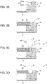
- FIGs. 3A to 3D show manufacturing steps of cooling unit 1.
- FIGs. 4A to 4C show the mechanism in which void 34 is formed in cooling unit 1.
- unit main body 10 is processed to form stepped portion 13 at the inner peripheral edge of an opening 14 side of peripheral wall portion 12.
- sealing body 20 is placed on stepped bottom surface 131 in a state in which side surface 21 of sealing body 20 and stepped side surface 132 butt each other to form butted portion 31 between side surface 21 of sealing body 20 and stepped side surface 132.
- gap 32 is formed between stepped side surface 132 and side surface 21 of sealing body 20 by size variation between unit main body 10 and sealing body 20.
- a width of gap 32 is 0.1 mm or more and 1.0 mm or less.
- rotary tool 40 is pushed into butted portion 31, and allowed to move along butted portion 31 while being rotated, and friction stir welding is carried out. Note here that positions of the start point and the end point of the friction stir welding need not be on butted portion 31.
- a rotating direction R and a travel direction M of rotary tool 40 are set such that a unit main body 10 side is an advancing side (AS) in the rotating direction R of rotary tool 40, and a sealing body 20 side is a retreating side (RS) in the rotating direction R of rotary tool 40. Furthermore, as described below, the rotational speed and the movement speed of rotary tool 40 are set so that void 34 remains in unit main body 10, and is formed outside plasticized region 33.
- Void 34 moves toward unit main body 10 as the advancing side by the rotation of rotary tool 40 as shown in FIG. 4C . Since centrifugal force is generated in void 34 as void 34 moves toward unit main body 10, void 34 is gradually apart from rotary tool 40. Then, the movement speed of void 34 becomes slow, and void 34 remains in unit main body 10 of the advancing side, and is formed outside plasticized region 33.
- Voids 34 are successively formed along the travel direction M of rotary tool 40.
- a plurality of voids 34 may be formed intermittently along the travel direction M of rotary tool 40.
- plasticized region 33 is formed along butted portion 31.
- void 34 is formed at a unit main body 10 side from the center C of plasticized region 33.
- cooling unit 1 in accordance with one exemplary embodiment includes unit main body 10 including bottom portion 11 and peripheral wall portion 12 rising from a peripheral edge of bottom portion 11, and sealing body 20 for sealing opening 14 of unit main body 10.
- Unit main body 10 has stepped portion 13 including stepped bottom surface 131 and stepped side surface 132 rising from stepped bottom surface 131 toward opening 14 at the inner peripheral edge of peripheral wall portion 12.
- Sealing body 20 is placed on stepped bottom surface 131 in a state in which side surface 21 of sealing body 20 and stepped side surface 132 butt each other.
- unit main body 10 is joined to sealing body 20 through plasticized region 33, and void 34 is formed in a unit main body 10 side from the center C of plasticized region 33.
- the method for manufacturing cooling unit 1 includes a first step of processing unit main body 10 having bottom portion 11 and peripheral wall portion 12 rising from a peripheral edge of bottom portion 11 to form stepped portion 13 on the inner peripheral edge of peripheral wall portion 12, stepped portion 13 including stepped bottom surface 131 and stepped side surface 132 rising from stepped bottom surface 131 toward opening 14 of unit main body 10 (see FIG. 3A ); a second step of placing sealing body 20 for sealing opening 14 of unit main body 10 on stepped bottom surface 131 in a state in which side surface 21 of sealing body 20 and stepped side surface 132 butt each other to form butted portion 31 having a gap between side surface 21 of sealing body 20 and stepped side surface 132 (see FIG. 3B ); and a third step of pushing rotary tool 40 into butted portion 31, moving rotary tool 40 along butted portion 31 while rotary tool 40 being rotated (see FIGs. 3C and 3D ).
- cooling unit 1 and the method for manufacturing cooling unit 1 even if the cooling unit has a large size and a complicated structure, the joining strength between unit main body 10 and sealing body 20 can be secured and the reliability can be improved.
- void 34 may be formed in any sites as long as it is formed in a unit main body 10 side from the center C from plasticized region 33. As shown in FIG. 5 , void 34 may be formed inside plasticized region 33. Also in this case, the same advantageous effect can be obtained as in cooling unit 1 described in the exemplary embodiment.
- void 34 can be positioned inside plasticized region 33.
- followability when sealing body 20 at the retreating side flows and fills the rear part of rotary tool 40 is deteriorated, and the moving speed of void 34 becomes slower than the moving speed of rotary tool 40. Therefore, void 34 does not move to unit main body 10 in the forward side and void 34 is formed inside plasticized region 33.
- the present disclosure can provide a cooling unit capable of securing joining strength between a unit main body and a sealing body and having good reliability, and a method for manufacturing the cooling unit.
- Cooling unit 1 of the present disclosure is suitable for use in electronic equipment on which a high-performance power module to be used for inverter control of a vehicle-mounted battery charger, an air-conditioning equipment, or the like, is installed.
Landscapes
- Engineering & Computer Science (AREA)
- Mechanical Engineering (AREA)
- Physics & Mathematics (AREA)
- Thermal Sciences (AREA)
- Microelectronics & Electronic Packaging (AREA)
- General Engineering & Computer Science (AREA)
- Pressure Welding/Diffusion-Bonding (AREA)
Abstract
Description
- The present invention relates to a cooling unit to be used for cooling vehicle-mounted equipment and other electronic equipment, and a method for manufacturing the cooling unit.
- In recent years, as a semiconductor device for power conversion used for inverter control of a vehicle-mounted battery charger, electronic equipment typified by airconditioners, air-conditioning equipment, personal computers, and the like, have been improved in performance, heating values of electronic components (a heat generating body) to be installed have been increased. It has been important to cool such electronic components.
- In electric vehicles and plug-in hybrid vehicles, a vehicle-mounted battery charger for charging a battery as a storage battery is installed. Usually, a vehicle-mounted battery charger is provided with a cooling unit to prevent components from being burned out due to a temperature rise during battery charging (see, for example,
PTLs 1 and 2). In particular, PTL 2 discloses a technique for joining a jacket main body as a metallic constituent member and a sealing body by friction stir welding, as a manufacturing method for maintaining water-tightness and air-tightness of a liquid-cooling type cooling unit. - Friction Stir Welding (FSW) is a method for solid-phase welding metal members to each other by moving a rotary tool along a butted portion of metal members while rotating the rotary tool, and by allowing the metal in the butted portion to plastically flow by frictional heat between the rotary tool and the metal members.
-
- PTL 1:
Japanese Patent No. 5572678 - PTL 2:
Japanese Patent Application Unexamined Publication No. 2015-131321 - A cooling unit according to one aspect of the present disclosure includes:
- a unit main body having a bottom portion and a peripheral wall portion rising from a peripheral edge of the bottom portion; and
- a sealing body for sealing an opening of the unit main body,
- wherein the unit main body is joined to the sealing body through a plasticized region, and a void is formed at a position close to the unit main body with respect to a center of the plasticized region.
- A method for manufacturing a cooling unit according to one aspect of the present disclosure includes:
- a first step of processing a unit main body having a bottom portion and a peripheral wall portion rising from a peripheral edge of the bottom portion to form a stepped portion in an inner peripheral edge of the peripheral wall portion, the stepped portion including a stepped bottom surface and a stepped side surface rising from the stepped bottom surface toward an opening of the unit main body;
- a second step of placing a sealing body for sealing the opening of the unit main body on the stepped bottom surface in a state in which a side surface of the sealing body and the stepped side surface butt each other to form a butted portion having a gap between the side surface of the sealing body and the stepped side surface; and
- a third step of pushing a rotary tool into the butted portion, moving the rotary tool along the butted portion while the rotary tool being rotated.
-
-
FIG. 1A is a perspective view showing a configuration of a cooling unit in accordance with one exemplary embodiment. -
FIG. 1B is a perspective view showing a configuration of the cooling unit in accordance with one exemplary embodiment. -
FIG. 2 is a sectional view showing a joined state of the cooling unit in accordance with one exemplary embodiment. -
FIG. 3A is a view showing a manufacturing step of the cooling unit in accordance with one exemplary embodiment. -
FIG. 3B is a view showing a manufacturing step of the cooling unit in accordance with one exemplary embodiment. -
FIG. 3C is a view showing a manufacturing step of the cooling unit in accordance with one exemplary embodiment. -
FIG. 3D is a view showing a manufacturing step of the cooling unit in accordance with one exemplary embodiment. -
FIG. 4A is a view showing a mechanism in which a void is formed in the cooling unit in accordance with one exemplary embodiment. -
FIG. 4B is a view showing a mechanism in which a void is formed in the cooling unit in accordance with one exemplary embodiment. -
FIG. 4C is a view showing a mechanism in which a void is formed in the cooling unit in accordance with one exemplary embodiment. -
FIG. 5 is a sectional view showing a joined state of the cooling unit in accordance with a modified example. - In a liquid-cooling jacket disclosed in PTL 2, a jacket main body has a complicated shape, and, therefore is formed of, for example, an aluminum alloy casting material. On the other hand, a product having a relatively simple shape, for example, a sealing body is formed of an aluminum alloy expanded material.
- In the case of manufacturing a liquid-cooling jacket by joining members of different types of aluminum alloys, it is common that the rigidity of the jacket main body is higher than that of the sealing body. In this case, when both members are joined by friction stir welding, a stirring pin as a rotating tool receives higher material resistance from the jacket main body than from the sealing body.
- Consequently, if the size variation of the jacket main body and the sealing body increases due to, for example, the increase in size of the liquid-cooling jacket, and shape variation occurs, for example, a gap occurs in a butted portion, it becomes difficult to stir different materials in balance by the stirring pin, and a void may be generated in a plasticized region after joining. Herein, the plasticized region is a region in which stirring is carried out by pushing a rotary tool into the butted portion, and a region in which plastically flowing occurs in the peripheral edge by the stirring. In addition, a stress concentration portion is formed in the plasticized region when a water pressure is applied by cooling water flowing in the liquid-cooling jacket. If a void exists in the vicinity of the stress concentration portion, it may cause crack propagation, and the joining strength may be lowered.
- An object of the present disclosure is to provide a cooling unit capable of securing the joining strength between a unit main body and a sealing body and having good reliability, and a method for manufacturing the cooling unit.
- Hereinafter, exemplary embodiments of a cooling unit in accordance with the present disclosure are described with reference to drawings. Note here that the present disclosure is not limited to the below-mentioned exemplary embodiments.
-
FIGs. 1A and 1B are perspective views each showing a configuration ofcooling unit 1 in accordance with one exemplary embodiment.FIG. 1A shows a state ofcooling unit 1 before joining in a exploded view, andFIG. 1B shows a state ofcooling unit 1 during joining.FIG. 2 is a sectional view showing a joined state ofcooling unit 1. - As shown in
FIGs. 1A and 1B ,cooling unit 1 includes unitmain body 10 andsealing body 20. Sealingbody 20 is joined to unitmain body 10 so as to close opening 14 of unitmain body 10, and thus, a sealed space in which cooling water flows is formed.Cooling unit 1 is provided in, for example, a vehicle-mounted battery charger, and prevents components from being burned out due to a temperature rise during battery charging. Although not shown, coolingunit 1 is provided with a circulation channel for allowing a cooling water to circulate in the sealed space. - Unit
main body 10 is a box member havingbottom portion 11 andperipheral wall portion 12 rising from a peripheral edge ofbottom portion 11. Unitmain body 10 has, for example, a rectangular box shape in a plan view and having arectangular opening 14. Furthermore, unitmain body 10 includes steppedportion 13 including steppedbottom surface 131 and steppedside surface 132 on the inner peripheral edge at an opening side ofperipheral wall portion 12. Steppedside surface 132 is formed so as to rise from steppedbottom surface 131 towardopening 14. - Sealing
body 20 is a flat plate member for closingopening 14 and has a size and shape corresponding to opening 14. Sealingbody 20 is placed on steppedbottom surface 131 in a state in which side surface 21 of sealingbody 20 and steppedside surface 132 butt each other, and joined to unitmain body 10 by friction stir welding.Plasticized region 33 is formed in a joined portion between unitmain body 10 and sealingbody 20. Unitmain body 10 is joined to sealingbody 20 through plasticizedregion 33. In the friction stir welding,rotary tool 40 for friction stir welding is used.Rotary tool 40 is formed of, for example, a tool steel, and includes columnar-shapedshoulder portion 41, and stirringpin 42 protruding from the lower end surface of shoulder portion 41 (see,FIG. 3C ). - In this exemplary embodiment, void 34, which is generated by friction stir welding, is formed in a unit
main body 10 side from the center C ofplasticized region 33. Specifically, void 34 is formed insideperipheral wall portion 12 of unitmain body 10. That is to say, when cooling water flows and water pressure is applied to coolingunit 1,stress concentration portion 35 is formed in a sealingbody 20 side of plasticizedregion 33.Void 34 is not present in the vicinity ofstress concentration portion 35. Therefore, it is possible to prevent crack from developing fromvoid 34 as a starting point and deteriorating the joining strength.Plasticized region 33 has a length in a first direction alongperipheral wall portion 12, and has a width in a second direction perpendicular to the first direction. The center C ofplasticized region 33 means the center of the width ofplasticized region 33. - Herein, even when void 34 is positioned in a unit
main body 10 side from the center C ofplasticized region 33, mechanical strength ofcooling unit 1 may be deteriorated depending on the size ofvoid 34. Thus, it is desirable that the size ofvoid 34 be 0.3 mm or more and 1.0 mm or less in the direction perpendicular to stepped side surface 132 (direction in parallel to bottom portion 11), or 0.3 mm or more and 1.0 mm or less in the direction perpendicular to stepped bottom surface 131 (direction perpendicular to bottom portion 11). Thus, the mechanical strength ofcooling unit 1 can be maintained. - The size of
void 34 is controlled by the size ofgap 32 formed between sealingbody 20 and unitmain body 10, as well as rotational speed and movement speed ofrotary tool 40. For example, when the rotational speed and the movement speed ofrotary tool 40 are constant, the size ofvoid 34 depends on the size ofgap 32. - Furthermore, unit
main body 10 and sealingbody 20 are formed of, for example, an aluminum alloy. This can provide thermal conductivity and mechanical strength required for coolingunit 1, and reduce the weight ofcooling unit 1. - In particular, a first aluminum alloy forming unit
main body 10 is a material having higher rigidity than a second aluminum alloy forming sealingbody 20. Thus, durability ofcooling unit 1 can be enhanced. - In addition, it is preferable that unit
main body 10 is formed of an aluminum alloy casting material. Thus, castability, strength, machinability, and the like, of unitmain body 10 can be enhanced. Furthermore, it is preferable that sealingbody 20 is formed of an aluminum alloy expanded material. Thus, workability and thermal conductivity can be enhanced. - The above-described
cooling unit 1 is manufactured by, for example, the following steps.FIGs. 3A to 3D show manufacturing steps ofcooling unit 1.FIGs. 4A to 4C show the mechanism in whichvoid 34 is formed incooling unit 1. - Firstly, as a first step, as shown in
FIG. 3A , unitmain body 10 is processed to form steppedportion 13 at the inner peripheral edge of anopening 14 side ofperipheral wall portion 12. - Next, as a second step, as shown in
FIG. 3B , sealingbody 20 is placed on steppedbottom surface 131 in a state in which side surface 21 of sealingbody 20 and steppedside surface 132 butt each other to form buttedportion 31 betweenside surface 21 of sealingbody 20 and steppedside surface 132. - At this time,
gap 32 is formed between steppedside surface 132 and side surface 21 of sealingbody 20 by size variation between unitmain body 10 and sealingbody 20. A width ofgap 32 is 0.1 mm or more and 1.0 mm or less. - Next, as a third step, as shown in
FIGs. 3C and 3D ,rotary tool 40 is pushed into buttedportion 31, and allowed to move along buttedportion 31 while being rotated, and friction stir welding is carried out. Note here that positions of the start point and the end point of the friction stir welding need not be on buttedportion 31. - Specifically, as shown in
FIG. 4A , a rotating direction R and a travel direction M ofrotary tool 40 are set such that a unitmain body 10 side is an advancing side (AS) in the rotating direction R ofrotary tool 40, and a sealingbody 20 side is a retreating side (RS) in the rotating direction R ofrotary tool 40. Furthermore, as described below, the rotational speed and the movement speed ofrotary tool 40 are set so that void 34 remains in unitmain body 10, and is formed outside plasticizedregion 33. - When
rotary tool 40 is allowed to move along buttedportion 31, the rear part in the traveling direction M of therotary tool 40 is filled by sealingbody 20 in the retreating side flowing in the rotating direction R. At this time,gap 32 is formed between sealingbody 20 and unitmain body 10, so that supply of materials become insufficient, and void 34 occurs in the rear part ofrotary tool 40. -
Void 34 moves toward unitmain body 10 as the advancing side by the rotation ofrotary tool 40 as shown inFIG. 4C . Since centrifugal force is generated invoid 34 asvoid 34 moves toward unitmain body 10, void 34 is gradually apart fromrotary tool 40. Then, the movement speed ofvoid 34 becomes slow, and void 34 remains in unitmain body 10 of the advancing side, and is formed outside plasticizedregion 33. - After
rotary tool 40 is rotated along buttedportion 31 once, and thenrotary tool 40 is pulled out. Thus, joining ofunit body 10 and sealingbody 20 is completed.Voids 34 are successively formed along the travel direction M ofrotary tool 40. A plurality ofvoids 34 may be formed intermittently along the travel direction M ofrotary tool 40. In the steps mentioned above, in coolingunit 1, plasticizedregion 33 is formed along buttedportion 31. Furthermore, void 34 is formed at a unitmain body 10 side from the center C ofplasticized region 33. - In this way, cooling
unit 1 in accordance with one exemplary embodiment includes unitmain body 10 includingbottom portion 11 andperipheral wall portion 12 rising from a peripheral edge ofbottom portion 11, and sealingbody 20 for sealingopening 14 of unitmain body 10. Unitmain body 10 has steppedportion 13 including steppedbottom surface 131 and steppedside surface 132 rising from steppedbottom surface 131 toward opening 14 at the inner peripheral edge ofperipheral wall portion 12. Sealingbody 20 is placed on steppedbottom surface 131 in a state in which side surface 21 of sealingbody 20 and steppedside surface 132 butt each other. Furthermore, unitmain body 10 is joined to sealingbody 20 through plasticizedregion 33, and void 34 is formed in a unitmain body 10 side from the center C ofplasticized region 33. - Furthermore, the method for manufacturing cooling
unit 1 includes a first step of processing unitmain body 10 havingbottom portion 11 andperipheral wall portion 12 rising from a peripheral edge ofbottom portion 11 to form steppedportion 13 on the inner peripheral edge ofperipheral wall portion 12, steppedportion 13 including steppedbottom surface 131 and steppedside surface 132 rising from steppedbottom surface 131 toward opening 14 of unit main body 10 (seeFIG. 3A ); a second step of placing sealingbody 20 for sealingopening 14 of unitmain body 10 on steppedbottom surface 131 in a state in which side surface 21 of sealingbody 20 and steppedside surface 132 butt each other to form buttedportion 31 having a gap betweenside surface 21 of sealingbody 20 and stepped side surface 132 (seeFIG. 3B ); and a third step of pushingrotary tool 40 into buttedportion 31, movingrotary tool 40 along buttedportion 31 whilerotary tool 40 being rotated (seeFIGs. 3C and 3D ). - According to cooling
unit 1 and the method for manufacturing coolingunit 1, even if the cooling unit has a large size and a complicated structure, the joining strength between unitmain body 10 and sealingbody 20 can be secured and the reliability can be improved. - More specifically, even if the size variation of unit
main body 10 and sealingbody 20 increases due to the increase in size ofcooling unit 1, and the shape variation occurs, for example, a gap is generated in buttedportion 31, sincevoid 34 is disposed in a place apart fromstress concentration portion 35, a crack can be prevented from developing fromvoid 34 as a starting point, and joining strength can be secured. - As mentioned above, disclosure by the present inventors is specifically described based on the exemplary embodiments, but the present disclosure is not limited to the above-described exemplary embodiments, and can be modified without departing from the scope thereof.
- For example, void 34 may be formed in any sites as long as it is formed in a unit
main body 10 side from the center C fromplasticized region 33. As shown inFIG. 5 , void 34 may be formed inside plasticizedregion 33. Also in this case, the same advantageous effect can be obtained as incooling unit 1 described in the exemplary embodiment. - For example, in the friction stir welding step, by increasing the rotational speed or the movement speed of
rotary tool 40, void 34 can be positioned inside plasticizedregion 33. In other words, when the rotational speed or the moving speed ofrotary tool 40 is increased, followability when sealingbody 20 at the retreating side flows and fills the rear part ofrotary tool 40 is deteriorated, and the moving speed ofvoid 34 becomes slower than the moving speed ofrotary tool 40. Therefore, void 34 does not move to unitmain body 10 in the forward side and void 34 is formed inside plasticizedregion 33. - It should be construed that the exemplary embodiments disclosed herein are illustrative in all pointes, and are not restrictive. The scope of the present disclosure is represented by the scope of the claims and not by the above description, and it is intended that all modifications within the sense and scope equivalent to the claims are involved in the scope of the present invention.
- The present disclosure can provide a cooling unit capable of securing joining strength between a unit main body and a sealing body and having good reliability, and a method for manufacturing the cooling unit.
-
Cooling unit 1 of the present disclosure is suitable for use in electronic equipment on which a high-performance power module to be used for inverter control of a vehicle-mounted battery charger, an air-conditioning equipment, or the like, is installed. -
- 1 cooling unit
- 10 unit main body
- 11 bottom portion
- 12 peripheral wall portion
- 13 stepped portion
- 131 stepped bottom surface
- 132 stepped side surface
- 14 opening
- 20 sealing body
- 21 side surface
- 31 butted portion
- 32 gap
- 33 plasticized region
- 34 void
- 35 stress concentration portion
Claims (9)
- A cooling unit comprising:a unit main body having a bottom portion and a peripheral wall portion rising from a peripheral edge of the bottom portion; anda sealing body for sealing an opening of the unit main body,wherein the unit main body is joined to the sealing body through a plasticized region, anda void is formed at a position close to the unit main body with respect to a center of the plasticized region.
- The cooling unit according to claim 1, wherein the void is formed inside the plasticized region.
- The cooling unit according to claim 1 or 2,wherein the unit main body comprises a first aluminum alloy,the sealing body comprises a second aluminum alloy, andthe first aluminum alloy has higher rigidity than rigidity of the second aluminum alloy.
- The cooling unit according to claim 3, wherein the unit main body comprises an aluminum alloy casting material, and the sealing body comprises an aluminum alloy expanded material.
- The cooling unit according to any one of claims 1 to 4, wherein the void has a size of 0.3 mm or more and 1.0 mm or less in a direction parallel to the bottom portion.
- The cooling unit according to any one of claims 1 to 5, wherein the void has a size of 0.3 mm or more and 1.0 mm or less in a direction perpendicular to the bottom portion.
- A method for manufacturing a cooling unit, the method comprising:a first step of processing a unit main body having a bottom portion and a peripheral wall portion rising from a peripheral edge of the bottom portion to form a stepped portion in an inner peripheral edge of the peripheral wall portion, the stepped portion including a stepped bottom surface and a stepped side surface rising from the stepped bottom surface toward an opening of the unit main body;a second step of placing a sealing body for sealing the opening of the unit main body on the stepped bottom surface in a state in which a side surface of the sealing body and the stepped side surface butt each other to form a butted portion having a gap between the side surface of the sealing body and the stepped side surface; anda third step of pushing a rotary tool into the butted portion, moving the rotary tool along the butted portion while the rotary tool being rotated.
- The method according to claim 7, wherein a width of the gap between the side surface of the sealing body and the stepped side surface is 0.1 mm or more and 1.0 mm or less.
- The method according to claim 7 or 8, wherein the third step comprises setting a rotating direction and a travel direction of the rotary tool for positioning the unit main body in an advance side in the rotating direction of the rotary tool, and the sealing body in the retreating side in a rotating direction.
Applications Claiming Priority (1)
| Application Number | Priority Date | Filing Date | Title |
|---|---|---|---|
| JP2021097588A JP7641569B2 (en) | 2021-06-10 | 2021-06-10 | Cooling unit and method for manufacturing the cooling unit |
Publications (2)
| Publication Number | Publication Date |
|---|---|
| EP4101578A1 true EP4101578A1 (en) | 2022-12-14 |
| EP4101578B1 EP4101578B1 (en) | 2025-08-20 |
Family
ID=81750430
Family Applications (1)
| Application Number | Title | Priority Date | Filing Date |
|---|---|---|---|
| EP22174543.3A Active EP4101578B1 (en) | 2021-06-10 | 2022-05-20 | Cooling unit and method for manufacturing cooling unit |
Country Status (3)
| Country | Link |
|---|---|
| US (1) | US11892248B2 (en) |
| EP (1) | EP4101578B1 (en) |
| JP (1) | JP7641569B2 (en) |
Families Citing this family (1)
| Publication number | Priority date | Publication date | Assignee | Title |
|---|---|---|---|---|
| KR102732025B1 (en) * | 2023-11-15 | 2024-11-19 | (주)케이에이치바텍 | Manufacturing method for metal frame structure for portable device |
Citations (5)
| Publication number | Priority date | Publication date | Assignee | Title |
|---|---|---|---|---|
| JP5572678B2 (en) | 2011-09-12 | 2014-08-13 | インフィネオン テクノロジーズ アーゲー | Semiconductor device including a clad base plate |
| JP2015131321A (en) | 2014-01-14 | 2015-07-23 | 日本軽金属株式会社 | Manufacturing method of liquid cooling jacket |
| JP2019076949A (en) * | 2017-10-27 | 2019-05-23 | 日本軽金属株式会社 | Method for manufacturing liquid-cooled jacket |
| US20190358740A1 (en) * | 2017-04-18 | 2019-11-28 | Nippon Light Metal Company, Ltd. | Method for manufacturing liquid-cooled jacket |
| WO2020095483A1 (en) * | 2018-11-05 | 2020-05-14 | 日本軽金属株式会社 | Liquid-cooled jacket manufacturing method and friction stir welding method |
Family Cites Families (9)
| Publication number | Priority date | Publication date | Assignee | Title |
|---|---|---|---|---|
| JP2001071156A (en) | 1999-08-31 | 2001-03-21 | Kobe Steel Ltd | Joining member, and its frictional agitation joining method |
| JP5045588B2 (en) | 2008-07-17 | 2012-10-10 | トヨタ自動車株式会社 | Friction stir welding tool and point welding method |
| CN105899321B (en) | 2014-01-14 | 2018-10-02 | 日本轻金属株式会社 | The manufacturing method of liquid-cooled jacket |
| WO2016072211A1 (en) * | 2014-11-05 | 2016-05-12 | 日本軽金属株式会社 | Method of manufacturing liquid-cooled jacket and liquid-cooled jacket |
| JP6617834B2 (en) | 2016-07-01 | 2019-12-11 | 日本軽金属株式会社 | Manufacturing method of heat transfer plate |
| JP6651068B2 (en) | 2017-06-19 | 2020-02-19 | アイセル株式会社 | Method for manufacturing structure, structure, and heat exchanger |
| JP7035892B2 (en) | 2018-08-06 | 2022-03-15 | 株式会社デンソー | A friction stir welding device and a method for manufacturing a friction stir welding body using the friction stir welding device. |
| JP7020562B2 (en) | 2018-09-18 | 2022-02-16 | 日本軽金属株式会社 | How to manufacture a liquid-cooled jacket |
| JP2021087962A (en) | 2019-12-02 | 2021-06-10 | 株式会社山本金属製作所 | Circuit-encapsulated member |
-
2021
- 2021-06-10 JP JP2021097588A patent/JP7641569B2/en active Active
-
2022
- 2022-05-20 EP EP22174543.3A patent/EP4101578B1/en active Active
- 2022-05-24 US US17/664,664 patent/US11892248B2/en active Active
Patent Citations (5)
| Publication number | Priority date | Publication date | Assignee | Title |
|---|---|---|---|---|
| JP5572678B2 (en) | 2011-09-12 | 2014-08-13 | インフィネオン テクノロジーズ アーゲー | Semiconductor device including a clad base plate |
| JP2015131321A (en) | 2014-01-14 | 2015-07-23 | 日本軽金属株式会社 | Manufacturing method of liquid cooling jacket |
| US20190358740A1 (en) * | 2017-04-18 | 2019-11-28 | Nippon Light Metal Company, Ltd. | Method for manufacturing liquid-cooled jacket |
| JP2019076949A (en) * | 2017-10-27 | 2019-05-23 | 日本軽金属株式会社 | Method for manufacturing liquid-cooled jacket |
| WO2020095483A1 (en) * | 2018-11-05 | 2020-05-14 | 日本軽金属株式会社 | Liquid-cooled jacket manufacturing method and friction stir welding method |
Also Published As
| Publication number | Publication date |
|---|---|
| US11892248B2 (en) | 2024-02-06 |
| US20220397353A1 (en) | 2022-12-15 |
| JP2022189168A (en) | 2022-12-22 |
| EP4101578B1 (en) | 2025-08-20 |
| JP7641569B2 (en) | 2025-03-07 |
Similar Documents
| Publication | Publication Date | Title |
|---|---|---|
| US10807188B2 (en) | Method of manufacturing liquid-cooled jacket | |
| US10471557B2 (en) | Method of manufacturing liquid-cooled jacket and liquid-cooled jacket | |
| CN111347862B (en) | Battery housing structure and vehicle mounting structure for battery housing structure | |
| JP6885263B2 (en) | How to manufacture a liquid-cooled jacket | |
| US20140210070A1 (en) | Friction Stir Welding Structure and Power Semiconductor Device | |
| CN103537793B (en) | The manufacture method of liquid-cooled jacket | |
| JP4962423B2 (en) | Manufacturing method of heat transfer plate | |
| EP4101578A1 (en) | Cooling unit and method for manufacturing cooling unit | |
| JP6471462B2 (en) | Manufacturing method of liquid cooling jacket | |
| JP6489219B2 (en) | Joining method, liquid cooling jacket manufacturing method, and liquid cooling jacket | |
| CN106961184B (en) | Fluid-cooled electric drive assembly, powertrain, vehicle, and method | |
| TW201710006A (en) | Liquid cooling jacket manufacturing method and liquid cooling jacket | |
| JP6885262B2 (en) | How to manufacture a liquid-cooled jacket | |
| WO2010041529A1 (en) | Method of manufacturing heat transfer plate | |
| US11026339B2 (en) | Method for producing electronics housings | |
| JP6656092B2 (en) | How to close the opening | |
| JP7437011B2 (en) | Metal structure manufacturing method and metal structure | |
| JP7020562B2 (en) | How to manufacture a liquid-cooled jacket | |
| CN112292915B (en) | Method for manufacturing housing for electronic device | |
| KR102603213B1 (en) | Cooling apparatus for power semiconductor and a method of manufacturing the same | |
| JP2021112757A (en) | How to manufacture a liquid-cooled jacket | |
| JP2020131263A (en) | Liquid-cooled jacket manufacturing method | |
| Grant et al. | Novel manufacturing technologies for high power induction and permanent magnet electric motors | |
| EP4672460A1 (en) | END PLATE, HOUSING, BATTERY, ELECTRICAL DEVICE AND HOUSING ASSEMBLY METHOD | |
| JP2002066766A (en) | Member joining method |
Legal Events
| Date | Code | Title | Description |
|---|---|---|---|
| PUAI | Public reference made under article 153(3) epc to a published international application that has entered the european phase |
Free format text: ORIGINAL CODE: 0009012 |
|
| STAA | Information on the status of an ep patent application or granted ep patent |
Free format text: STATUS: THE APPLICATION HAS BEEN PUBLISHED |
|
| AK | Designated contracting states |
Kind code of ref document: A1 Designated state(s): AL AT BE BG CH CY CZ DE DK EE ES FI FR GB GR HR HU IE IS IT LI LT LU LV MC MK MT NL NO PL PT RO RS SE SI SK SM TR |
|
| STAA | Information on the status of an ep patent application or granted ep patent |
Free format text: STATUS: REQUEST FOR EXAMINATION WAS MADE |
|
| 17P | Request for examination filed |
Effective date: 20230613 |
|
| RBV | Designated contracting states (corrected) |
Designated state(s): AL AT BE BG CH CY CZ DE DK EE ES FI FR GB GR HR HU IE IS IT LI LT LU LV MC MK MT NL NO PL PT RO RS SE SI SK SM TR |
|
| GRAP | Despatch of communication of intention to grant a patent |
Free format text: ORIGINAL CODE: EPIDOSNIGR1 |
|
| STAA | Information on the status of an ep patent application or granted ep patent |
Free format text: STATUS: GRANT OF PATENT IS INTENDED |
|
| RIC1 | Information provided on ipc code assigned before grant |
Ipc: B23K 20/12 20060101AFI20250402BHEP |
|
| INTG | Intention to grant announced |
Effective date: 20250416 |
|
| RIN1 | Information on inventor provided before grant (corrected) |
Inventor name: ISHIKAWA, RYO Inventor name: NEBASHI, TOMONARI Inventor name: MAEDE, MASATO Inventor name: OCHI, SHOZO |
|
| GRAS | Grant fee paid |
Free format text: ORIGINAL CODE: EPIDOSNIGR3 |
|
| GRAA | (expected) grant |
Free format text: ORIGINAL CODE: 0009210 |
|
| STAA | Information on the status of an ep patent application or granted ep patent |
Free format text: STATUS: THE PATENT HAS BEEN GRANTED |
|
| AK | Designated contracting states |
Kind code of ref document: B1 Designated state(s): AL AT BE BG CH CY CZ DE DK EE ES FI FR GB GR HR HU IE IS IT LI LT LU LV MC MK MT NL NO PL PT RO RS SE SI SK SM TR |
|
| REG | Reference to a national code |
Ref country code: GB Ref legal event code: FG4D |
|
| REG | Reference to a national code |
Ref country code: CH Ref legal event code: EP |
|
| REG | Reference to a national code |
Ref country code: IE Ref legal event code: FG4D |
|
| REG | Reference to a national code |
Ref country code: DE Ref legal event code: R096 Ref document number: 602022019666 Country of ref document: DE |
|
| REG | Reference to a national code |
Ref country code: NL Ref legal event code: MP Effective date: 20250820 |
|
| PG25 | Lapsed in a contracting state [announced via postgrant information from national office to epo] |
Ref country code: IS Free format text: LAPSE BECAUSE OF FAILURE TO SUBMIT A TRANSLATION OF THE DESCRIPTION OR TO PAY THE FEE WITHIN THE PRESCRIBED TIME-LIMIT Effective date: 20251220 |
|
| PG25 | Lapsed in a contracting state [announced via postgrant information from national office to epo] |
Ref country code: NO Free format text: LAPSE BECAUSE OF FAILURE TO SUBMIT A TRANSLATION OF THE DESCRIPTION OR TO PAY THE FEE WITHIN THE PRESCRIBED TIME-LIMIT Effective date: 20251120 |
|
| REG | Reference to a national code |
Ref country code: LT Ref legal event code: MG9D |
|
| PG25 | Lapsed in a contracting state [announced via postgrant information from national office to epo] |
Ref country code: PT Free format text: LAPSE BECAUSE OF FAILURE TO SUBMIT A TRANSLATION OF THE DESCRIPTION OR TO PAY THE FEE WITHIN THE PRESCRIBED TIME-LIMIT Effective date: 20251222 |
|
| PG25 | Lapsed in a contracting state [announced via postgrant information from national office to epo] |
Ref country code: FI Free format text: LAPSE BECAUSE OF FAILURE TO SUBMIT A TRANSLATION OF THE DESCRIPTION OR TO PAY THE FEE WITHIN THE PRESCRIBED TIME-LIMIT Effective date: 20250820 |
|
| PG25 | Lapsed in a contracting state [announced via postgrant information from national office to epo] |
Ref country code: HR Free format text: LAPSE BECAUSE OF FAILURE TO SUBMIT A TRANSLATION OF THE DESCRIPTION OR TO PAY THE FEE WITHIN THE PRESCRIBED TIME-LIMIT Effective date: 20250820 Ref country code: NL Free format text: LAPSE BECAUSE OF FAILURE TO SUBMIT A TRANSLATION OF THE DESCRIPTION OR TO PAY THE FEE WITHIN THE PRESCRIBED TIME-LIMIT Effective date: 20250820 |
|
| PG25 | Lapsed in a contracting state [announced via postgrant information from national office to epo] |
Ref country code: GR Free format text: LAPSE BECAUSE OF FAILURE TO SUBMIT A TRANSLATION OF THE DESCRIPTION OR TO PAY THE FEE WITHIN THE PRESCRIBED TIME-LIMIT Effective date: 20251121 |
|
| PG25 | Lapsed in a contracting state [announced via postgrant information from national office to epo] |
Ref country code: SE Free format text: LAPSE BECAUSE OF FAILURE TO SUBMIT A TRANSLATION OF THE DESCRIPTION OR TO PAY THE FEE WITHIN THE PRESCRIBED TIME-LIMIT Effective date: 20250820 |
|
| PG25 | Lapsed in a contracting state [announced via postgrant information from national office to epo] |
Ref country code: LV Free format text: LAPSE BECAUSE OF FAILURE TO SUBMIT A TRANSLATION OF THE DESCRIPTION OR TO PAY THE FEE WITHIN THE PRESCRIBED TIME-LIMIT Effective date: 20250820 |
|
| PG25 | Lapsed in a contracting state [announced via postgrant information from national office to epo] |
Ref country code: BG Free format text: LAPSE BECAUSE OF FAILURE TO SUBMIT A TRANSLATION OF THE DESCRIPTION OR TO PAY THE FEE WITHIN THE PRESCRIBED TIME-LIMIT Effective date: 20250820 Ref country code: PL Free format text: LAPSE BECAUSE OF FAILURE TO SUBMIT A TRANSLATION OF THE DESCRIPTION OR TO PAY THE FEE WITHIN THE PRESCRIBED TIME-LIMIT Effective date: 20250820 |
|
| PG25 | Lapsed in a contracting state [announced via postgrant information from national office to epo] |
Ref country code: RS Free format text: LAPSE BECAUSE OF FAILURE TO SUBMIT A TRANSLATION OF THE DESCRIPTION OR TO PAY THE FEE WITHIN THE PRESCRIBED TIME-LIMIT Effective date: 20251120 |
|
| PG25 | Lapsed in a contracting state [announced via postgrant information from national office to epo] |
Ref country code: ES Free format text: LAPSE BECAUSE OF FAILURE TO SUBMIT A TRANSLATION OF THE DESCRIPTION OR TO PAY THE FEE WITHIN THE PRESCRIBED TIME-LIMIT Effective date: 20250820 |
|
| REG | Reference to a national code |
Ref country code: AT Ref legal event code: MK05 Ref document number: 1826816 Country of ref document: AT Kind code of ref document: T Effective date: 20250820 |
|
| PG25 | Lapsed in a contracting state [announced via postgrant information from national office to epo] |
Ref country code: SM Free format text: LAPSE BECAUSE OF FAILURE TO SUBMIT A TRANSLATION OF THE DESCRIPTION OR TO PAY THE FEE WITHIN THE PRESCRIBED TIME-LIMIT Effective date: 20250820 |
|
| PG25 | Lapsed in a contracting state [announced via postgrant information from national office to epo] |
Ref country code: DK Free format text: LAPSE BECAUSE OF FAILURE TO SUBMIT A TRANSLATION OF THE DESCRIPTION OR TO PAY THE FEE WITHIN THE PRESCRIBED TIME-LIMIT Effective date: 20250820 |
|
| PG25 | Lapsed in a contracting state [announced via postgrant information from national office to epo] |
Ref country code: AT Free format text: LAPSE BECAUSE OF FAILURE TO SUBMIT A TRANSLATION OF THE DESCRIPTION OR TO PAY THE FEE WITHIN THE PRESCRIBED TIME-LIMIT Effective date: 20250820 |
|
| PG25 | Lapsed in a contracting state [announced via postgrant information from national office to epo] |
Ref country code: IT Free format text: LAPSE BECAUSE OF FAILURE TO SUBMIT A TRANSLATION OF THE DESCRIPTION OR TO PAY THE FEE WITHIN THE PRESCRIBED TIME-LIMIT Effective date: 20250820 |
|
| PG25 | Lapsed in a contracting state [announced via postgrant information from national office to epo] |
Ref country code: CZ Free format text: LAPSE BECAUSE OF FAILURE TO SUBMIT A TRANSLATION OF THE DESCRIPTION OR TO PAY THE FEE WITHIN THE PRESCRIBED TIME-LIMIT Effective date: 20250820 |
|
| PG25 | Lapsed in a contracting state [announced via postgrant information from national office to epo] |
Ref country code: SK Free format text: LAPSE BECAUSE OF FAILURE TO SUBMIT A TRANSLATION OF THE DESCRIPTION OR TO PAY THE FEE WITHIN THE PRESCRIBED TIME-LIMIT Effective date: 20250820 Ref country code: EE Free format text: LAPSE BECAUSE OF FAILURE TO SUBMIT A TRANSLATION OF THE DESCRIPTION OR TO PAY THE FEE WITHIN THE PRESCRIBED TIME-LIMIT Effective date: 20250820 |