EP4101571A1 - Device for controlling wire electrical discharge machining apparatus - Google Patents
Device for controlling wire electrical discharge machining apparatus Download PDFInfo
- Publication number
- EP4101571A1 EP4101571A1 EP21750634.4A EP21750634A EP4101571A1 EP 4101571 A1 EP4101571 A1 EP 4101571A1 EP 21750634 A EP21750634 A EP 21750634A EP 4101571 A1 EP4101571 A1 EP 4101571A1
- Authority
- EP
- European Patent Office
- Prior art keywords
- corner
- corner control
- machining
- unit
- control
- Prior art date
- Legal status (The legal status is an assumption and is not a legal conclusion. Google has not performed a legal analysis and makes no representation as to the accuracy of the status listed.)
- Pending
Links
Images



Classifications
-
- B—PERFORMING OPERATIONS; TRANSPORTING
- B23—MACHINE TOOLS; METAL-WORKING NOT OTHERWISE PROVIDED FOR
- B23H—WORKING OF METAL BY THE ACTION OF A HIGH CONCENTRATION OF ELECTRIC CURRENT ON A WORKPIECE USING AN ELECTRODE WHICH TAKES THE PLACE OF A TOOL; SUCH WORKING COMBINED WITH OTHER FORMS OF WORKING OF METAL
- B23H7/00—Processes or apparatus applicable to both electrical discharge machining and electrochemical machining
- B23H7/02—Wire-cutting
- B23H7/06—Control of the travel curve of the relative movement between electrode and workpiece
-
- G—PHYSICS
- G05—CONTROLLING; REGULATING
- G05B—CONTROL OR REGULATING SYSTEMS IN GENERAL; FUNCTIONAL ELEMENTS OF SUCH SYSTEMS; MONITORING OR TESTING ARRANGEMENTS FOR SUCH SYSTEMS OR ELEMENTS
- G05B13/00—Adaptive control systems, i.e. systems automatically adjusting themselves to have a performance which is optimum according to some preassigned criterion
- G05B13/02—Adaptive control systems, i.e. systems automatically adjusting themselves to have a performance which is optimum according to some preassigned criterion electric
- G05B13/0265—Adaptive control systems, i.e. systems automatically adjusting themselves to have a performance which is optimum according to some preassigned criterion electric the criterion being a learning criterion
-
- G—PHYSICS
- G06—COMPUTING OR CALCULATING; COUNTING
- G06N—COMPUTING ARRANGEMENTS BASED ON SPECIFIC COMPUTATIONAL MODELS
- G06N20/00—Machine learning
Definitions
- the present invention relates to a controller for controlling a wire electrical discharge machining apparatus.
- a controller for controlling a wire electrical discharge machining apparatus executes machining by combining corner shapes of a machining process (corner shapes of an NC program) as illustrated in Fig. 8 .
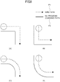
- Fig. 8 illustrates diagrams for describing examples of corner shapes of the NC program.
- the examples indicate a plurality of examples such as an outer sharp edge corner ((A) in Fig. 8 ) and an inner sharp edge corner ((B) in Fig. 8 ) formed by two continuous cutting feed blocks, as well as an outer arc corner where a wire path is on the outer side of a circle of an arc block ((C) in Fig. 8 ) and an inner arc corner where a wire path is on the inner side of a circle of an arc block ((D) in Fig. 8 ), and the like.
- the controller for controlling the wire electrical machine performs corner control corresponding to the corner shapes by performing switching between different machining conditions (machining speeds, electrical discharge power intensities, and the like).
- the machining accuracy is increased by employing, for example, a method that detects in advance overlapping of the corner control segments, and performs control by using a value resulting from interpolation of a change amount of the machining conditions of the corner control in the segments, or a method that determines in advance the corner control to be performed preferentially.
- Patent Document 1 Japanese Unexamined Patent Application, Publication No. H08-168925
- a controller for controlling a wire electrical discharge machining apparatus including a machining unit that performs discharge machining on a workpiece by executing a machining program includes: a storage unit that stores the machining program and a plurality of corner control patterns each of which is applicable to a respective one of corner parts; a control unit that performs corner control for switching to a prescribed machining condition based on a corner shape when machining is to be performed on the corner part; a calculation unit that calculates corner control segments from a start point and an end point of the corner control; and a selection unit that selects, from the storage unit, one of the corner control patterns to be preferentially performed in a case where the corner control segments calculated by the calculation unit overlap.
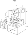
- Fig. 1 is a schematic perspective view illustrating the wire electrical discharge machining apparatus 1 according to the present embodiment.
- the wire electrical discharge machining apparatus 1 illustrated in Fig. 1 performs electrical discharge machining on a workpiece W (machining target) while relatively moving a wire electrode and the workpiece W according to a machining program.
- the wire electrical discharge machining apparatus 1 repeatedly performs, on the workpiece W, a plurality of electrical discharge machining steps from roughing to finishing.
- the wire electrical discharge machining apparatus 1 creates a machining path (referred to as a wire diameter compensated path) that is offset, by an offset value (including a wire diameter compensation value), from a program shape (machining shape) of the workpiece according to the machining program.
- the offset values for the machining steps are different from each other.
- the wire electrical discharge machining apparatus 1 relatively moves the wire electrode and the workpiece W according to the machining path.
- the wire electrical discharge machining apparatus 1 includes a bed 2, a work-pan 3, a workpiece table 4, a wire electrode 5, a wire bobbin 6, a motor/powder brake 7, a brake roller 8, a pinch roller 9, an upper guide 10, a lower guide 11, a pinch roller 12, a feed roller 13, a wire collection box 14, a control unit 15, a machining power supply 16, and a controller 20 for controlling the wire electrical discharge machining apparatus 1 according to the embodiment.
- the controller 20 is constituted by an operation processor such as a Digital Signal Processor (DSP), a Field-Programmable Gate Array (FPGA), or the like. Various functions of the controller 20 are achieved by executing software (program, application).
- the controller 20 controls the wire electrical discharge machining apparatus 1 that performs wire electrical discharge machining on the workpiece W by moving the wire electrode 5 loaded to the apparatus 1.
- the controller 20 includes a rewritable storage unit 22 to store a program for analyzing the machining program, determination conditions the program refers to, and parameters (including offset values).
- the bed 2 is a machine bed where the work-pan 3 is placed.
- the work-pan 3 is a space which is filled with a dielectric working fluid and in which electrical discharge machining is performed.
- the workpiece table 4 is a table where the workpiece W is loaded, and a relative position with respect to the wire electrode 5 is determined under the control of the controller 20.
- the wire electrode 5 is fed out from the wire bobbin 6, and collected into the wire collection box 14 via the brake roller 8 driven by the motor/powder brake 7, the pinch roller 9, the upper guide 10, the lower guide 11, the pinch roller 12, and the feed roller 13.
- the wire electrode 5 is supported by the upper guide 10 and the lower guide 11 inside the work-pan 3, and stretched in a straight form between the upper guide 10 and the lower guide 11.
- the wire electrode 5 stretched in a straight form in a state of being soaked in the dielectric working fluid performs electrical discharge machining on the workpiece W.
- the wire bobbin 6 receives, from a torque motor (not shown), a prescribed torque in an inverse direction of the feeding direction of the wire electrode 5. Positions of the upper guide 10 and the lower guide 11 may be fixed or changeable by the program corresponding to the shape of the workpiece W, the fixing method, and the machining shape of the workpiece W.
- the machining power supply 16 enables electrical discharge machining to be performed on the workpiece W by applying a high frequency voltage to the wire electrode 5. However, when a failure occurs with machining performed along concentric machining path, a machining path creation unit 23 performs control to select a concentric machining path the shapes of the corner parts of which are concentric (non-identical radii).
- the controller 20 may be provided to the wire electrical discharge machining apparatus 1 or the control unit 15, or may be provided to a computer different from those.
- the wire electrical discharge machining apparatus 1 has a Z-axis that moves in parallel to the wire electrode, an XY-axis that moves in a plane perpendicular to the wire electrode, and a UV-axis that moves in parallel to the XY-axis and that is for inclining the wire electrode, and includes the workpiece table where workpiece to be machined is placed.
- Each of the axes is configured to move by being driven by a servo motor or the like.
- a command for moving each of the axes is given by the controller 20. Furthermore, recording of the voltage during electrical discharge and discharge delay time as well as determination of the type of discharge pulse are performed by an arithmetic unit included in the controller 20 or an external arithmetic unit connected to the controller 20.
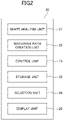
- Fig. 2 is a block diagram for describing the controller for controlling the wire electrical discharge machining apparatus according to the first embodiment. This example corresponds to the functional configuration of the controller 20 illustrated in Fig. 1 .
- the controller 20 for controlling the wire electrical discharge machining apparatus, illustrated in Fig. 2 includes: a shape analysis unit 21 as a calculation unit, the storage unit 22, the machining path creation unit 23, a selection unit 24, a display unit 25, and the control unit 15.
- the shape analysis unit 21 prefetches the machining program, and analyzes the program shape (machining shape) of the workpiece.
- the storage unit 22 stores various offset values (machining parameters) and the like to be used in machining steps from roughing to finishing.
- the storage unit 22 stores a plurality of corner control patterns for allowing switching between prescribed machining conditions defined based on the corner shapes when the wire electrode 5 performs machining on the corner parts of the workpiece W as will be described later.
- the storage unit 22 stores, in the order of priority, a plurality of corner control patterns SP1 to SPN adaptable to one corner control selected for the processing to be described later.
- the corner control patterns SP1 to SPN are a plurality of corner control patterns adaptable to one corner control, when performing electrical discharge machining on continuous overlapping corner control segments.
- the plurality of corner control patterns stored in the storage unit 22 are several types of patterns obtained by narrowing down and evaluating experimental values and the like.
- the storage unit 22 is a rewritable memory such as an EEPROM, for example.
- the selection unit 24 selects, from a plurality of corner control patterns SP1 to SPN stored in the storage unit 22, one corner control pattern of high priority for the one of the analyzed continuous corner control segments.
- the selection unit 24 illustrated in Fig. 2 applies the corner control pattern SP2 that is higher in priority with respect to a shape signal analyzed by the shape analysis unit 21. Note that detailed procedures will be described by referring to a flowchart illustrated in Fig. 3 .
- the machining path creation unit 23 creates the corner control that is offset, by the offset value stored in the storage unit 22, from the machining program shape analyzed by the shape analysis unit 21. Specifically, the machining path creation unit 23 normally creates the corner control so as to select a concentric machining path with which the shapes of the corner parts are concentric arcs (same radii).
- the shape analysis unit 21 and the machining path creation unit 23 may be combined into one corner control unit.
- the machining path creation unit (corner control unit) 23 performs control such that the shapes of the corner parts come to be in concentric arcs, that is, in same radius shapes. Furthermore, the machining path creation unit 23 can also create the corner control offset by the offset value stored in the storage unit 22.
- the selection unit 24 for selecting one of the corner control patterns stored in the storage unit 22, when the shape analysis unit 21 detects corner control that overlaps for the corner control segments.
- the rewritable storage unit 22 stores the program for analyzing the machining program, determination conditions the program refers to, and parameters (including offset values).
- the shape analysis unit 21 as the calculation unit calculates the start point and the end point of the corner control from the corner shape that is generated by way of analysis of the machining program, and determines whether there is an overlapping state occurring in the corner control segments, examples of which are illustrated in Figs. 4 to 6 to be described later.
- the selection unit 24 selects one corner control pattern from a plurality of corner control patterns SP1 to SPN stored in the storage unit 22 for adapting to the corner control. Then, the selection unit 24 outputs a final shape signal corresponding to the selected one corner control pattern to the control unit 15.
- Fig. 3 is a flowchart illustrating a control procedure performed by the controller for controlling the wire electrical discharge machining apparatus according to the embodiment.
- S1 to S5 indicate the respective steps, and the control programs corresponding to the steps are stored in the storage unit 22 and executed by the control unit 15 of the controller 20 that predominantly performs the CNC control.
- the shape analysis unit 21 starts analysis of the CNC program, and detects a corner shape signal (for example, consisted by a 16-bit signal) (S2).
- the number of bits or the like of the shape signal is not limited to 16 bits.
- the instruction to start the machining processing may be provided from a graphical user interface (GUI) displayed in the display unit 25.
- GUI graphical user interface
- the shape analysis unit 21 determines whether it is detected that the corner shape overlaps in the corner control segments based on the state of the continuous shape signals detected in S2.
- the process proceeds to S5 where a shape signal for executing optimal continuous corner machining is output to the control unit 15, and the processing is ended.
- the selection unit 24 selects one high-priority corner control pattern from the corner control patterns stored in the storage unit 22 (S4), and the process proceeds to S5.
- S5 a shape signal corresponding to the corner control pattern selected by the selection unit 24 is output to the control unit 15, and the processing is ended.
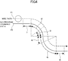
- Figs. 4 to 6 are diagrams each illustrating an example of a shape pattern of a plurality of continuous corner control segments to be analyzed by the shape analysis unit 21.
- the examples of the shape patterns of the plurality of continuous corner control segments will be described.
- a path P2 indicated by a thick solid line denotes a CNC program command path
- a path P1 indicated by a thick broken line denotes a path of the wire electrode 5.
- the continuous corner path pattern illustrated in Fig. 4 is a continuous corner pattern example in which an outer arc pre-corner control segment I1 - an outer arc in-corner control segment I2 - an inner arc in-corner control segment I5 - an inner arc post-corner control segment I6 are set.
- an outer arc in-corner and inner arc pre-corner control overlapping segment I3 is set.
- an inner arc in-corner and outer arc post-corner control overlapping segment I4 is set.
- the continuous corner path pattern illustrated in Fig. 5 is a continuous corner path pattern example in which an inner arc pre-corner control segment I11 - an inner arc in-corner control segment 113 - an inner arc post-corner control segment 114 are set.
- the continuous corner pattern is a continuous corner path pattern example in which an outer sharp edge pre-corner and inner arc pre-corner control overlapping segment (linear path segment) I11 and an outer sharp edge post-corner and inner arc in-corner control overlapping segment (arc path segment) 112 are set.
- the continuous corner path pattern illustrated in Fig. 6 is a continuous corner path pattern example in which an inner arc post-corner control segment 121 and an outer arc pre-corner control overlapping segment 122 are set.
- the continuous corner pattern is a continuous corner path pattern example in which, in the inner arc post-corner control segment 121 and the outer arc pre-corner control segment 123, an inner arc post-corner and outer arc pre-corner control overlapping segment 122 is set.
- the shape analysis unit 21 can detect the overlapping state of the corner control segments from the corner shape signal to be processed, according to the control procedure illustrated in Fig. 3 .
- the shape analysis unit 21 can also detect the overlapping state of the corner control segments from the corner shape signal to be processed.
- the shape analysis unit 21 can also detect the overlapping state of the corner control segments from the corner shape signal to be processed. Accordingly, the selection unit 24 selects, from the storage unit 22, the corner control pattern optimal for each of the corner control segments detected in Figs. 4 to 6 , and outputs it to the control unit 15.
- a high priority corner control pattern can be selected, whereby machining accuracy based on the corner control can be improved.
- the selection method of the corner control pattern by the selection unit 24 described is the case of selecting one corner control pattern of high priority from the corner control patterns in which the control segments overlap.
- the selection unit 24 as another selection method of the preferential corner control pattern performed by the selection unit 24, described is a case where a user gives an instruction via a screen to select a corner control pattern on which control is to be preferentially performed when an overlapping section of the corner control segments is drawn on the screen of the display unit 25.
- the display unit 25 may be a touch panel, for example.
- the user may operate an operation unit such as a keyboard and make selection while viewing the display screen of the display unit 25.
- the corner control pattern on which the control is to be preferentially performed the corner control pattern selected by the user is output to the control unit 15.
- a plurality of corner control pattern candidates applicable to overlapping corner control can be displayed on the display unit 25.
- the configuration in which the user selects one intended corner control pattern from the displayed plurality of corner control pattern candidates makes it possible to reflect the user's intended corner control to actual machining of the corner parts.
- the corner control can be executed according to the optimal corner control pattern selected by the user.
- the optimal corner control is not always applied to all combination patterns in a case where the corner control is performed by using values interpolated by a same method or in a case where the preferential corner control is determined based on a specific determination criterion. Furthermore, in order to determine the priority order of the corner control patterns with fine machining accuracy, it is necessary to perform brute-force machining experiments on different corner control patterns.
- machine learning using a learning unit 26 illustrated in Fig. 2 is executed. More specifically, in the embodiment, executed is the so-called supervised machine learning that uses, as the input data, corner parts having overlapping corner control segments (which may include corner shapes (radius, angle), material of workpiece, thickness, wire diameter, and the like), and that has, as labels, the corner control patterns selected by the user for each of the corner parts.
- Fig. 7 is a block diagram for describing a controller for controlling a wire electrical discharge machining apparatus according to a third embodiment.
- the controller 20 illustrated in Fig. 7 includes the learning unit 26 in addition to the components illustrated in Fig. 2 .
- the learning unit 26 collects priority order selection results of each of the continuous corner control patterns determined by the user, and stores the results in the storage unit 22. Note here that the processing for selecting the priority order may be collection based on the selection made by input via a panel displayed on the display unit 25 or may be collection made by input from other operation units.
- the learning unit 26 when machining is performed on the corner part including continuous patterns that have not been selected before, the learning unit 26 outputs a corner control pattern of continuous corner parts having a similar characteristic, and the selection unit 24 makes selection of the corner control pattern output by the learning unit 26.
- the selection information of the corner control patterns determined by the user and learned by the learning unit 26 is collected in the storage unit 22, even a corner part including continuous patterns that have not been selected before can be subjected to appropriate corner control, which is automatically selected.
- the corner control pattern selected by the selection unit 24 may not be applied to all of the detected shape signals but the shape analysis unit 21 may preferentially perform sharp corner control when detecting that there is a sharp corner shape signal in the machining segment designated by the user.
- the shape analysis unit 21 may omit signals other than the shape to which the control is preferentially performed (may change corresponding value from "1" to "0") and output only the shape signal to perform the control.
- the selection unit 24 can also output, to the control unit 15, only the shape signal that has been acquired by applying compensation processing on the shape signal output from the shape analysis unit 21.
- the selection unit 24 may output a plurality of shape signals and perform corner control simultaneously. Furthermore, the selection unit 24 may omit all shape signals associated with all corners detected by the shape analysis unit 21 (may change all the corresponding values from "1" to "0") and perform no corner control.
Landscapes
- Engineering & Computer Science (AREA)
- Artificial Intelligence (AREA)
- Chemical & Material Sciences (AREA)
- Chemical Kinetics & Catalysis (AREA)
- Electrochemistry (AREA)
- Mechanical Engineering (AREA)
- Evolutionary Computation (AREA)
- Computer Vision & Pattern Recognition (AREA)
- Health & Medical Sciences (AREA)
- Medical Informatics (AREA)
- Software Systems (AREA)
- Physics & Mathematics (AREA)
- General Physics & Mathematics (AREA)
- Automation & Control Theory (AREA)
- Electrical Discharge Machining, Electrochemical Machining, And Combined Machining (AREA)
- Numerical Control (AREA)
Abstract
Description
- The present invention relates to a controller for controlling a wire electrical discharge machining apparatus.
- A controller for controlling a wire electrical discharge machining apparatus executes machining by combining corner shapes of a machining process (corner shapes of an NC program) as illustrated in
Fig. 8 . -
Fig. 8 illustrates diagrams for describing examples of corner shapes of the NC program. The examples indicate a plurality of examples such as an outer sharp edge corner ((A) inFig. 8 ) and an inner sharp edge corner ((B) inFig. 8 ) formed by two continuous cutting feed blocks, as well as an outer arc corner where a wire path is on the outer side of a circle of an arc block ((C) inFig. 8 ) and an inner arc corner where a wire path is on the inner side of a circle of an arc block ((D) inFig. 8 ), and the like. - Since how the machining state changes vary depending on those corner shapes, the controller for controlling the wire electrical machine performs corner control corresponding to the corner shapes by performing switching between different machining conditions (machining speeds, electrical discharge power intensities, and the like).
- In a case of a shape including a plurality of continuous corner control segments illustrated in
Fig. 8 (hereinafter, referred to as continuous corners), the machining conditions are switched abruptly and the machining state changes significantly. Therefore, it may not be possible to achieve desired machining accuracy in some cases. - Thus, in the field of controllers for controlling an electrical discharge machining apparatus, the machining accuracy is increased by employing, for example, a method that detects in advance overlapping of the corner control segments, and performs control by using a value resulting from interpolation of a change amount of the machining conditions of the corner control in the segments, or a method that determines in advance the corner control to be performed preferentially.
- Patent Document 1:
Japanese Unexamined Patent Application, Publication No. H08-168925 - However, there has been a problem in that a sufficient machining accuracy cannot be achieved with the control by the same interpolation method or the same priority order determination method for various combination patterns of the continuous corners described above.
- Therefore, in the field of the controllers for controlling the electrical discharge machining apparatus, it is desirable to be able to improve the machining accuracy even in a case of performing machining on a plurality of overlapping corner control segments.
- A controller for controlling a wire electrical discharge machining apparatus including a machining unit that performs discharge machining on a workpiece by executing a machining program according to the present disclosure includes: a storage unit that stores the machining program and a plurality of corner control patterns each of which is applicable to a respective one of corner parts; a control unit that performs corner control for switching to a prescribed machining condition based on a corner shape when machining is to be performed on the corner part; a calculation unit that calculates corner control segments from a start point and an end point of the corner control; and a selection unit that selects, from the storage unit, one of the corner control patterns to be preferentially performed in a case where the corner control segments calculated by the calculation unit overlap.
- According to an aspect of the present disclosure, it is possible to improve the machining accuracy for continuous corner even in a case where a plurality of corner control segments overlap.
-
-
Fig. 1 is a perspective view illustrating an overview of a wire electrical discharge machining apparatus according to an embodiment; -
Fig. 2 is a block diagram for describing a controller for controlling a wire electrical discharge machining apparatus according to a first embodiment; -
Fig. 3 is a flowchart illustrating a control procedure performed by the controller for controlling the wire electrical discharge machining apparatus; -
Fig. 4 is a diagram illustrating an example of shape pattern of a plurality of continuous corner control segments; -
Fig. 5 is a diagram illustrating an example of shape pattern of a plurality of continuous corner control segments; -
Fig. 6 is a diagram illustrating an example of shape pattern of a plurality of continuous corner control segments; -
Fig. 7 is a block diagram for describing a controller for controlling a wire electrical discharge machining apparatus according to a third embodiment; and -
Fig. 8 illustrates diagrams for describing examples of corner shapes of an NC program. - Embodiments will be described in detail with reference to the accompanying drawings. First, by referring to
Fig. 1 , a configuration of a wire electricaldischarge machining apparatus 1 will be described. -
Fig. 1 is a schematic perspective view illustrating the wire electricaldischarge machining apparatus 1 according to the present embodiment. The wire electricaldischarge machining apparatus 1 illustrated inFig. 1 performs electrical discharge machining on a workpiece W (machining target) while relatively moving a wire electrode and the workpiece W according to a machining program. The wire electricaldischarge machining apparatus 1 repeatedly performs, on the workpiece W, a plurality of electrical discharge machining steps from roughing to finishing. - In each of the machining steps, the wire electrical
discharge machining apparatus 1 creates a machining path (referred to as a wire diameter compensated path) that is offset, by an offset value (including a wire diameter compensation value), from a program shape (machining shape) of the workpiece according to the machining program. The offset values for the machining steps are different from each other. In each of the machining steps, the wire electricaldischarge machining apparatus 1 relatively moves the wire electrode and the workpiece W according to the machining path. - The wire electrical
discharge machining apparatus 1 includes abed 2, a work-pan 3, a workpiece table 4, awire electrode 5, awire bobbin 6, a motor/powder brake 7, abrake roller 8, apinch roller 9, anupper guide 10, alower guide 11, apinch roller 12, afeed roller 13, awire collection box 14, acontrol unit 15, amachining power supply 16, and acontroller 20 for controlling the wire electricaldischarge machining apparatus 1 according to the embodiment. - Note here that the
controller 20 is constituted by an operation processor such as a Digital Signal Processor (DSP), a Field-Programmable Gate Array (FPGA), or the like. Various functions of thecontroller 20 are achieved by executing software (program, application). Thecontroller 20 controls the wire electricaldischarge machining apparatus 1 that performs wire electrical discharge machining on the workpiece W by moving thewire electrode 5 loaded to theapparatus 1. - The
controller 20 includes arewritable storage unit 22 to store a program for analyzing the machining program, determination conditions the program refers to, and parameters (including offset values). - The
bed 2 is a machine bed where the work-pan 3 is placed. The work-pan 3 is a space which is filled with a dielectric working fluid and in which electrical discharge machining is performed. The workpiece table 4 is a table where the workpiece W is loaded, and a relative position with respect to thewire electrode 5 is determined under the control of thecontroller 20. - The
wire electrode 5 is fed out from thewire bobbin 6, and collected into thewire collection box 14 via thebrake roller 8 driven by the motor/powder brake 7, thepinch roller 9, theupper guide 10, thelower guide 11, thepinch roller 12, and thefeed roller 13. - The
wire electrode 5 is supported by theupper guide 10 and thelower guide 11 inside the work-pan 3, and stretched in a straight form between theupper guide 10 and thelower guide 11. Thewire electrode 5 stretched in a straight form in a state of being soaked in the dielectric working fluid performs electrical discharge machining on the workpiece W. - The
wire bobbin 6 receives, from a torque motor (not shown), a prescribed torque in an inverse direction of the feeding direction of thewire electrode 5. Positions of theupper guide 10 and thelower guide 11 may be fixed or changeable by the program corresponding to the shape of the workpiece W, the fixing method, and the machining shape of the workpiece W. Themachining power supply 16 enables electrical discharge machining to be performed on the workpiece W by applying a high frequency voltage to thewire electrode 5. However, when a failure occurs with machining performed along concentric machining path, a machiningpath creation unit 23 performs control to select a concentric machining path the shapes of the corner parts of which are concentric (non-identical radii). Thecontroller 20 may be provided to the wire electricaldischarge machining apparatus 1 or thecontrol unit 15, or may be provided to a computer different from those. - As illustrated in
Fig. 1 , the wire electricaldischarge machining apparatus 1 has a Z-axis that moves in parallel to the wire electrode, an XY-axis that moves in a plane perpendicular to the wire electrode, and a UV-axis that moves in parallel to the XY-axis and that is for inclining the wire electrode, and includes the workpiece table where workpiece to be machined is placed. Each of the axes is configured to move by being driven by a servo motor or the like. - In the present embodiment, a command for moving each of the axes is given by the
controller 20. Furthermore, recording of the voltage during electrical discharge and discharge delay time as well as determination of the type of discharge pulse are performed by an arithmetic unit included in thecontroller 20 or an external arithmetic unit connected to thecontroller 20. -
Fig. 2 is a block diagram for describing the controller for controlling the wire electrical discharge machining apparatus according to the first embodiment. This example corresponds to the functional configuration of thecontroller 20 illustrated inFig. 1 . Thecontroller 20 for controlling the wire electrical discharge machining apparatus, illustrated inFig. 2 includes: ashape analysis unit 21 as a calculation unit, thestorage unit 22, the machiningpath creation unit 23, aselection unit 24, adisplay unit 25, and thecontrol unit 15. - The
shape analysis unit 21 prefetches the machining program, and analyzes the program shape (machining shape) of the workpiece. Thestorage unit 22 stores various offset values (machining parameters) and the like to be used in machining steps from roughing to finishing. Thestorage unit 22 stores a plurality of corner control patterns for allowing switching between prescribed machining conditions defined based on the corner shapes when thewire electrode 5 performs machining on the corner parts of the workpiece W as will be described later. - The
storage unit 22 according to the present embodiment stores, in the order of priority, a plurality of corner control patterns SP1 to SPN adaptable to one corner control selected for the processing to be described later. Note here that the corner control patterns SP1 to SPN are a plurality of corner control patterns adaptable to one corner control, when performing electrical discharge machining on continuous overlapping corner control segments. Furthermore, the plurality of corner control patterns stored in thestorage unit 22 are several types of patterns obtained by narrowing down and evaluating experimental values and the like. Note that thestorage unit 22 is a rewritable memory such as an EEPROM, for example. - When the
shape analysis unit 21 determines that machining paths overlap in continuous corner control segments to be described later, theselection unit 24 selects, from a plurality of corner control patterns SP1 to SPN stored in thestorage unit 22, one corner control pattern of high priority for the one of the analyzed continuous corner control segments. - In the present embodiment, for example, in a case where the corner control pattern SP1 (middle of arc > after arc > before arc) and the corner control pattern SP2 (after arc > middle of arc > before arc), which are adaptable to corner control, are selectable for a corner overlapping control segment, the
selection unit 24 illustrated inFig. 2 applies the corner control pattern SP2 that is higher in priority with respect to a shape signal analyzed by theshape analysis unit 21. Note that detailed procedures will be described by referring to a flowchart illustrated inFig. 3 . - The machining
path creation unit 23 creates the corner control that is offset, by the offset value stored in thestorage unit 22, from the machining program shape analyzed by theshape analysis unit 21. Specifically, the machiningpath creation unit 23 normally creates the corner control so as to select a concentric machining path with which the shapes of the corner parts are concentric arcs (same radii). - In
Fig. 2 , theshape analysis unit 21 and the machiningpath creation unit 23 may be combined into one corner control unit. - When a corner machining path CP1-CP2-CP3 is extracted from the program shape analyzed by the
shape analysis unit 21, the machining path creation unit (corner control unit) 23 performs control such that the shapes of the corner parts come to be in concentric arcs, that is, in same radius shapes. Furthermore, the machiningpath creation unit 23 can also create the corner control offset by the offset value stored in thestorage unit 22. - Hereinafter, described is an example of processing performed by the
selection unit 24 for selecting one of the corner control patterns stored in thestorage unit 22, when theshape analysis unit 21 detects corner control that overlaps for the corner control segments. Note that therewritable storage unit 22 stores the program for analyzing the machining program, determination conditions the program refers to, and parameters (including offset values). - First, the
shape analysis unit 21 as the calculation unit calculates the start point and the end point of the corner control from the corner shape that is generated by way of analysis of the machining program, and determines whether there is an overlapping state occurring in the corner control segments, examples of which are illustrated inFigs. 4 to 6 to be described later. - When determining that there is an overlapping state in the corner control segments from the shape signal analyzed by the
shape analysis unit 21, theselection unit 24 selects one corner control pattern from a plurality of corner control patterns SP1 to SPN stored in thestorage unit 22 for adapting to the corner control. Then, theselection unit 24 outputs a final shape signal corresponding to the selected one corner control pattern to thecontrol unit 15. -
Fig. 3 is a flowchart illustrating a control procedure performed by the controller for controlling the wire electrical discharge machining apparatus according to the embodiment. Note that S1 to S5 indicate the respective steps, and the control programs corresponding to the steps are stored in thestorage unit 22 and executed by thecontrol unit 15 of thecontroller 20 that predominantly performs the CNC control. - When the CNC program is input in response to an instruction from an operation unit or the like of the wire electrical
discharge machining apparatus 1 to start the machining processing (S1), theshape analysis unit 21 starts analysis of the CNC program, and detects a corner shape signal (for example, consisted by a 16-bit signal) (S2). - Note that the number of bits or the like of the shape signal is not limited to 16 bits. Furthermore, the instruction to start the machining processing may be provided from a graphical user interface (GUI) displayed in the
display unit 25. - Next, the
shape analysis unit 21 determines whether it is detected that the corner shape overlaps in the corner control segments based on the state of the continuous shape signals detected in S2. When theshape analysis unit 21 determines that no overlapping state is detected in the corner control segments from the shape signals, the process proceeds to S5 where a shape signal for executing optimal continuous corner machining is output to thecontrol unit 15, and the processing is ended. - On the other hand, when the
shape analysis unit 21 determines in S3 that an overlapping state is detected in the corner control segments from the shape signals, theselection unit 24 selects one high-priority corner control pattern from the corner control patterns stored in the storage unit 22 (S4), and the process proceeds to S5. In S5, a shape signal corresponding to the corner control pattern selected by theselection unit 24 is output to thecontrol unit 15, and the processing is ended. - Note that the change in the machining condition of the continuous corner parts also occurs in the blocks before and after the corner parts. Therefore, not only the corner block but also the blocks before and after that block may be included in the control segments.
-
Figs. 4 to 6 are diagrams each illustrating an example of a shape pattern of a plurality of continuous corner control segments to be analyzed by theshape analysis unit 21. Hereinafter, the examples of the shape patterns of the plurality of continuous corner control segments will be described. - In
Figs. 4 to 6 , a path P2 indicated by a thick solid line denotes a CNC program command path, and a path P1 indicated by a thick broken line denotes a path of thewire electrode 5. The continuous corner path pattern illustrated inFig. 4 is a continuous corner pattern example in which an outer arc pre-corner control segment I1 - an outer arc in-corner control segment I2 - an inner arc in-corner control segment I5 - an inner arc post-corner control segment I6 are set. - As for the continuous corner path pattern, in the outer arc in-
corner control segment 12, an outer arc in-corner and inner arc pre-corner control overlapping segment I3 is set. Similarly, in the inner arc in-corner control segment I5, an inner arc in-corner and outer arc post-corner control overlapping segment I4 is set. Moreover, it is a corner pattern in which the path is set such that the inner arc in-corner and outer arc post-corner control overlapping segment I4 continuous with the outer arc in-corner and inner arc pre-cornercontrol overlapping segment 13. - The continuous corner path pattern illustrated in
Fig. 5 is a continuous corner path pattern example in which an inner arc pre-corner control segment I11 - an inner arc in-corner control segment 113 - an inner arc post-cornercontrol segment 114 are set. - The continuous corner pattern is a continuous corner path pattern example in which an outer sharp edge pre-corner and inner arc pre-corner control overlapping segment (linear path segment) I11 and an outer sharp edge post-corner and inner arc in-corner control overlapping segment (arc path segment) 112 are set.
- The continuous corner path pattern illustrated in
Fig. 6 is a continuous corner path pattern example in which an inner arc post-corner control segment 121 and an outer arc pre-cornercontrol overlapping segment 122 are set. - The continuous corner pattern is a continuous corner path pattern example in which, in the inner arc post-corner control segment 121 and the outer arc
pre-corner control segment 123, an inner arc post-corner and outer arc pre-cornercontrol overlapping segment 122 is set. - In the present embodiment, in the case of the continuous arc blocks as in
Fig. 4 , theshape analysis unit 21 can detect the overlapping state of the corner control segments from the corner shape signal to be processed, according to the control procedure illustrated inFig. 3 . - Similarly, even in a case where the start point or the end point of the arc block is a sharp edge corner as in
Fig. 5 , theshape analysis unit 21 can also detect the overlapping state of the corner control segments from the corner shape signal to be processed. - Similarly, even in a case where the length of a linear block between a corner and a corner is smaller than the total control distance of the corner parts before and after as in
Fig. 6 , theshape analysis unit 21 can also detect the overlapping state of the corner control segments from the corner shape signal to be processed. Accordingly, theselection unit 24 selects, from thestorage unit 22, the corner control pattern optimal for each of the corner control segments detected inFigs. 4 to 6 , and outputs it to thecontrol unit 15. - According to the present embodiment, even when machining is performed on a plurality of corner control segments overlapping with each other, a high priority corner control pattern can be selected, whereby machining accuracy based on the corner control can be improved.
- In the first embodiment, as the selection method of the corner control pattern by the
selection unit 24, described is the case of selecting one corner control pattern of high priority from the corner control patterns in which the control segments overlap. - In the second embodiment, as another selection method of the preferential corner control pattern performed by the
selection unit 24, described is a case where a user gives an instruction via a screen to select a corner control pattern on which control is to be preferentially performed when an overlapping section of the corner control segments is drawn on the screen of thedisplay unit 25. Note that thedisplay unit 25 may be a touch panel, for example. Furthermore, the user may operate an operation unit such as a keyboard and make selection while viewing the display screen of thedisplay unit 25. - When the user selects, via the screen of the
display unit 25, the corner control pattern on which the control is to be preferentially performed, the corner control pattern selected by the user is output to thecontrol unit 15. - In this way, by analysis of the corner parts performed by the
shape analysis unit 21, a plurality of corner control pattern candidates applicable to overlapping corner control can be displayed on thedisplay unit 25. The configuration in which the user selects one intended corner control pattern from the displayed plurality of corner control pattern candidates makes it possible to reflect the user's intended corner control to actual machining of the corner parts. - According to the present embodiment, even when machining is performed on a plurality of corner control segments overlapping with each other, the corner control can be executed according to the optimal corner control pattern selected by the user.
- Note that there are a great number of patterns having overlapping corner shapes as illustrated in the first embodiment, and combinations thereof including factors like corner radius and angle are innumerable. Therefore, the optimal corner control is not always applied to all combination patterns in a case where the corner control is performed by using values interpolated by a same method or in a case where the preferential corner control is determined based on a specific determination criterion. Furthermore, in order to determine the priority order of the corner control patterns with fine machining accuracy, it is necessary to perform brute-force machining experiments on different corner control patterns.
- However, with such a method, it requires a great number of steps for determining the corner control pattern and takes time to develop. Thus, in the present embodiment, machine learning using a
learning unit 26 illustrated inFig. 2 is executed. More specifically, in the embodiment, executed is the so-called supervised machine learning that uses, as the input data, corner parts having overlapping corner control segments (which may include corner shapes (radius, angle), material of workpiece, thickness, wire diameter, and the like), and that has, as labels, the corner control patterns selected by the user for each of the corner parts. -
Fig. 7 is a block diagram for describing a controller for controlling a wire electrical discharge machining apparatus according to a third embodiment. Thecontroller 20 illustrated inFig. 7 includes thelearning unit 26 in addition to the components illustrated inFig. 2 . InFig. 7 , thelearning unit 26 collects priority order selection results of each of the continuous corner control patterns determined by the user, and stores the results in thestorage unit 22. Note here that the processing for selecting the priority order may be collection based on the selection made by input via a panel displayed on thedisplay unit 25 or may be collection made by input from other operation units. - Thereby, in the present embodiment, when machining is performed on the corner part including continuous patterns that have not been selected before, the
learning unit 26 outputs a corner control pattern of continuous corner parts having a similar characteristic, and theselection unit 24 makes selection of the corner control pattern output by thelearning unit 26. - According to the third embodiment, since the selection information of the corner control patterns determined by the user and learned by the
learning unit 26 is collected in thestorage unit 22, even a corner part including continuous patterns that have not been selected before can be subjected to appropriate corner control, which is automatically selected. - In the first embodiment, described is a case where the corner control pattern selected by the
selection unit 24 is applied to all of the analyzed shape signals. - However, in the first to third embodiments, the corner control pattern selected by the
selection unit 24 may not be applied to all of the detected shape signals but theshape analysis unit 21 may preferentially perform sharp corner control when detecting that there is a sharp corner shape signal in the machining segment designated by the user. - According to the present embodiment, it is possible to achieve the corner control according to which the corner control pattern selected by the
selection unit 24 is applied to only the segment designated by the user from among the corner parts analyzed by theshape analysis unit 21. - According to the first to fourth embodiments, in a case where shape signals of a plurality of continuous corners are output, the
shape analysis unit 21 may omit signals other than the shape to which the control is preferentially performed (may change corresponding value from "1" to "0") and output only the shape signal to perform the control. Thereby, theselection unit 24 can also output, to thecontrol unit 15, only the shape signal that has been acquired by applying compensation processing on the shape signal output from theshape analysis unit 21. - Furthermore, depending on the shapes of continuous corner parts detected by the
shape analysis unit 21, theselection unit 24 may output a plurality of shape signals and perform corner control simultaneously. Furthermore, theselection unit 24 may omit all shape signals associated with all corners detected by the shape analysis unit 21 (may change all the corresponding values from "1" to "0") and perform no corner control. - According to the present embodiment, it is possible to achieve the corner control that conforms to the intention of the user, by combining the corner control using the corner control pattern and the corner control intended by the user.
- Note that the present disclosure is not limited to the embodiments described above, but includes modifications and improvements within the range in which the object of the present disclosure can be achieved.
-
- 1:
- Wire electrical discharge machining apparatus
- 15:
- Control unit
- 20:
- Controller
- 22:
- Storage unit
- 23:
- Machining path creation unit
- 24:
- Selection unit
- 25:
- Display unit
- 26:
- Learning unit
Claims (3)
- A controller for controlling a wire electrical discharge machining apparatus including a machining unit that performs discharge machining on a workpiece by executing a machining program, the controller comprising:a storage unit that stores the machining program and a plurality of corner control patterns each of which is applicable to a respective one of corner parts;a control unit that performs corner control for switching to a prescribed machining condition based on a corner shape when machining is to be performed on the corner part;a calculation unit that calculates corner control segments from a start point and an end point of the corner control; anda selection unit that selects, from the storage unit, one of the corner control patterns to be preferentially performed in a case where the corner control segments calculated by the calculation unit overlap.
- The controller for controlling the wire electrical discharge machining apparatus according to claim 1, further comprising a display unit that displays a drawing result of the machining program and the corner part where the corner control segments calculated by the calculation unit overlap, wherein
in a case where a user selects one of the corner control patterns from the storage unit based on display of the display unit, the selection unit selects the corner control pattern selected by the user. - The controller for controlling the wire electrical discharge machining apparatus according to claim 2, further comprising a learning unit that learns the corner control pattern selected by the user, for each of the corner parts where the corner control segments overlap.
Applications Claiming Priority (2)
| Application Number | Priority Date | Filing Date | Title |
|---|---|---|---|
| JP2020017844 | 2020-02-05 | ||
| PCT/JP2021/003744 WO2021157575A1 (en) | 2020-02-05 | 2021-02-02 | Device for controlling wire electrical discharge machining apparatus |
Publications (2)
| Publication Number | Publication Date |
|---|---|
| EP4101571A1 true EP4101571A1 (en) | 2022-12-14 |
| EP4101571A4 EP4101571A4 (en) | 2024-03-20 |
Family
ID=77200215
Family Applications (1)
| Application Number | Title | Priority Date | Filing Date |
|---|---|---|---|
| EP21750634.4A Pending EP4101571A4 (en) | 2020-02-05 | 2021-02-02 | Device for controlling wire electrical discharge machining apparatus |
Country Status (6)
| Country | Link |
|---|---|
| US (1) | US12485496B2 (en) |
| EP (1) | EP4101571A4 (en) |
| JP (1) | JP7364700B2 (en) |
| CN (1) | CN115003443B (en) |
| TW (1) | TWI865723B (en) |
| WO (1) | WO2021157575A1 (en) |
Families Citing this family (3)
| Publication number | Priority date | Publication date | Assignee | Title |
|---|---|---|---|---|
| CN117836081A (en) * | 2021-09-03 | 2024-04-05 | 发那科株式会社 | Control device and control method of wire discharge machining machine |
| CN118265587A (en) * | 2021-11-26 | 2024-06-28 | 发那科株式会社 | Control device of wire electric discharge machine and control method of wire electric discharge machine |
| JP7822534B1 (en) * | 2025-06-20 | 2026-03-02 | 三菱電機株式会社 | Wire electric discharge machining device, wire electric discharge machining method, control program, and wire electric discharge machining system |
Family Cites Families (13)
| Publication number | Priority date | Publication date | Assignee | Title |
|---|---|---|---|---|
| JPS5524806A (en) | 1978-07-31 | 1980-02-22 | Mitsubishi Electric Corp | Method for producing medium for working instruction record |
| JPH01228727A (en) | 1988-03-03 | 1989-09-12 | Mitsubishi Electric Corp | Wire cut electric discharge machining method |
| JP2952369B2 (en) | 1994-10-03 | 1999-09-27 | 株式会社ソディック | Wire cut electric discharge machining method |
| JPH08168925A (en) | 1994-12-19 | 1996-07-02 | Fanuc Ltd | Numerical controller for wire cut electric discharge machine |
| JP4137384B2 (en) | 1998-12-02 | 2008-08-20 | 三菱電機株式会社 | EDM machine machining condition pass / fail judgment device |
| JP5255167B1 (en) | 2011-09-01 | 2013-08-07 | 株式会社アステック | Small hole electric discharge machine |
| CN105682840B (en) | 2013-10-31 | 2017-10-20 | 三菱电机株式会社 | Wire discharge processing apparatus |
| JP6140228B2 (en) | 2015-08-27 | 2017-05-31 | ファナック株式会社 | Wire electrical discharge machine for machining while adjusting machining conditions |
| JP6680714B2 (en) | 2017-03-30 | 2020-04-15 | ファナック株式会社 | Control device and machine learning device for wire electric discharge machine |
| EP3446820B1 (en) | 2017-08-22 | 2025-05-07 | Agie Charmilles SA | Wire electrical discharge machining methods |
| JP6680748B2 (en) | 2017-11-17 | 2020-04-15 | ファナック株式会社 | Control device and machine learning device |
| KR102290055B1 (en) * | 2017-12-08 | 2021-08-13 | 현대모비스 주식회사 | Apparatus for controlling group driving and method thereof |
| JP7424810B2 (en) | 2019-12-06 | 2024-01-30 | ファナック株式会社 | Program editing device and wire electrical discharge machine |
-
2021
- 2021-02-02 US US17/759,699 patent/US12485496B2/en active Active
- 2021-02-02 EP EP21750634.4A patent/EP4101571A4/en active Pending
- 2021-02-02 CN CN202180011056.5A patent/CN115003443B/en active Active
- 2021-02-02 WO PCT/JP2021/003744 patent/WO2021157575A1/en not_active Ceased
- 2021-02-02 JP JP2021575809A patent/JP7364700B2/en active Active
- 2021-02-03 TW TW110104061A patent/TWI865723B/en active
Also Published As
| Publication number | Publication date |
|---|---|
| TWI865723B (en) | 2024-12-11 |
| TW202130436A (en) | 2021-08-16 |
| JPWO2021157575A1 (en) | 2021-08-12 |
| US20230076571A1 (en) | 2023-03-09 |
| WO2021157575A1 (en) | 2021-08-12 |
| US12485496B2 (en) | 2025-12-02 |
| CN115003443B (en) | 2024-08-27 |
| EP4101571A4 (en) | 2024-03-20 |
| JP7364700B2 (en) | 2023-10-18 |
| CN115003443A (en) | 2022-09-02 |
Similar Documents
| Publication | Publication Date | Title |
|---|---|---|
| US12485496B2 (en) | Device for controlling wire electrical discharge machining apparatus | |
| US9370817B2 (en) | Method and system for programming the control of a multiaxis forming machine and forming machine | |
| JP4813616B1 (en) | Numerical control device for machine tool having speed control function during arc motion | |
| JP2006293537A (en) | Numerical control apparatus | |
| EP1762322A2 (en) | Machining condition setting method for electrical discharge machines | |
| KR102577377B1 (en) | Wire electrical discharge machine and machining program editor | |
| US20130241923A1 (en) | Machining state information displaying device | |
| US10146213B2 (en) | Numerical controller for automatically switching acceleration/deceleration setting in accordance with machining content or state | |
| JP7372191B2 (en) | Program editing device, wire electrical discharge machine and program editing method | |
| US11163290B2 (en) | Control device and axial feed control method | |
| JP6808868B1 (en) | Wire electric discharge machining method and wire electric discharge machining equipment | |
| CN117120198B (en) | Numerical control devices and computer-readable storage media | |
| US20240231309A1 (en) | Numerical controller | |
| US6658317B2 (en) | Method for setting a moving position in a machine tool | |
| JP6760998B2 (en) | Control device for wire electric discharge machine | |
| JP4867876B2 (en) | Numerical control device, numerical control program, and storage medium storing numerical control program | |
| WO2000012251A1 (en) | Wire electric discharge method and apparatus | |
| US11099541B2 (en) | Motor control device for performing an axial feed control method | |
| JP2021144284A (en) | Machining program management device, management system, management method | |
| JP3642278B2 (en) | Wire electric discharge machining method and apparatus | |
| WO2024252583A1 (en) | Simulation device and computer-readable storage medium | |
| JP7822534B1 (en) | Wire electric discharge machining device, wire electric discharge machining method, control program, and wire electric discharge machining system | |
| JP2005059207A (en) | Wire electric discharge machining apparatus and wire electric discharge machining method |
Legal Events
| Date | Code | Title | Description |
|---|---|---|---|
| STAA | Information on the status of an ep patent application or granted ep patent |
Free format text: STATUS: THE INTERNATIONAL PUBLICATION HAS BEEN MADE |
|
| PUAI | Public reference made under article 153(3) epc to a published international application that has entered the european phase |
Free format text: ORIGINAL CODE: 0009012 |
|
| STAA | Information on the status of an ep patent application or granted ep patent |
Free format text: STATUS: REQUEST FOR EXAMINATION WAS MADE |
|
| 17P | Request for examination filed |
Effective date: 20220823 |
|
| AK | Designated contracting states |
Kind code of ref document: A1 Designated state(s): AL AT BE BG CH CY CZ DE DK EE ES FI FR GB GR HR HU IE IS IT LI LT LU LV MC MK MT NL NO PL PT RO RS SE SI SK SM TR |
|
| DAV | Request for validation of the european patent (deleted) | ||
| DAX | Request for extension of the european patent (deleted) | ||
| A4 | Supplementary search report drawn up and despatched |
Effective date: 20240215 |
|
| RIC1 | Information provided on ipc code assigned before grant |
Ipc: B23H 7/06 20060101AFI20240209BHEP |