EP4101566B1 - Spiral step twist drill bit - Google Patents
Spiral step twist drill bit Download PDFInfo
- Publication number
- EP4101566B1 EP4101566B1 EP22178374.9A EP22178374A EP4101566B1 EP 4101566 B1 EP4101566 B1 EP 4101566B1 EP 22178374 A EP22178374 A EP 22178374A EP 4101566 B1 EP4101566 B1 EP 4101566B1
- Authority
- EP
- European Patent Office
- Prior art keywords
- spiral
- cutting
- drill bit
- edge
- twist drill
- Prior art date
- Legal status (The legal status is an assumption and is not a legal conclusion. Google has not performed a legal analysis and makes no representation as to the accuracy of the status listed.)
- Active
Links
Images
Classifications
-
- B—PERFORMING OPERATIONS; TRANSPORTING
- B23—MACHINE TOOLS; METAL-WORKING NOT OTHERWISE PROVIDED FOR
- B23B—TURNING; BORING
- B23B51/00—Tools for drilling machines
- B23B51/02—Twist drills
-
- B—PERFORMING OPERATIONS; TRANSPORTING
- B23—MACHINE TOOLS; METAL-WORKING NOT OTHERWISE PROVIDED FOR
- B23B—TURNING; BORING
- B23B51/00—Tools for drilling machines
- B23B51/009—Stepped drills
-
- B—PERFORMING OPERATIONS; TRANSPORTING
- B23—MACHINE TOOLS; METAL-WORKING NOT OTHERWISE PROVIDED FOR
- B23B—TURNING; BORING
- B23B2251/00—Details of tools for drilling machines
- B23B2251/04—Angles, e.g. cutting angles
- B23B2251/043—Helix angles
- B23B2251/046—Variable
Definitions
- This application relates to cutting tools, and more particularity to a spiral step twist drill bit.
- a twist drill is a tool that drills a round hole in a workpiece by rotational cutting with respect to a fixed axis, and named for its spiral chip flute resembling twist.
- the twist drill bit can be clamped on a manual or electric hand-held drilling tool or on a drilling machine, milling machine, lathe or even a machining center for use.
- the conventional twist drill relies on two symmetrically-distributed straight cutting edges to simultaneously complete a corresponding metal cutting amount during drilling, requiring a relatively larger power. Moreover, the edges are prone to damage due to a large reaction force.
- a step twist drill bit on the market which, by means of the stepped cutting, not only enables easy positioning during the layered drilling, but also reduces the cutting resistance and heat generation, improves drilling efficiency, extends the service life, greatly enhancing the drilling performance.
- the step twist drill bit also enables the precise drilling of round holes, and reduces the generation of the burrs. Therefore, the step twist drill bit has attracted a lot of attention in the field of mechanical machining.
- steps of the existing step twist drill bit are distributed spaced apart in parallel along an axial direction of the drill bit, and the step surface is perpendicular to the drill bit axis, resulting in overlapped processing and attenuation of cutting efficiency. Furthermore, the cutting chips will be held at the step surfaces, affecting the subsequent processing.
- an increment rate of the pitch of the spiral cutting groove is 1.2-1.5.
Landscapes
- Engineering & Computer Science (AREA)
- Mechanical Engineering (AREA)
- Drilling Tools (AREA)
Description
- This application relates to cutting tools, and more particularity to a spiral step twist drill bit.
- A twist drill is a tool that drills a round hole in a workpiece by rotational cutting with respect to a fixed axis, and named for its spiral chip flute resembling twist. Currently, there are 2, 3 or more flutes on the twist drill bit, where the 2-flute twist drill bit is dominant. The twist drill bit can be clamped on a manual or electric hand-held drilling tool or on a drilling machine, milling machine, lathe or even a machining center for use.
- The conventional twist drill relies on two symmetrically-distributed straight cutting edges to simultaneously complete a corresponding metal cutting amount during drilling, requiring a relatively larger power. Moreover, the edges are prone to damage due to a large reaction force. At present, there is a step twist drill bit on the market, which, by means of the stepped cutting, not only enables easy positioning during the layered drilling, but also reduces the cutting resistance and heat generation, improves drilling efficiency, extends the service life, greatly enhancing the drilling performance. Moreover, the step twist drill bit also enables the precise drilling of round holes, and reduces the generation of the burrs. Therefore, the step twist drill bit has attracted a lot of attention in the field of mechanical machining.
- Nevertheless, steps of the existing step twist drill bit are distributed spaced apart in parallel along an axial direction of the drill bit, and the step surface is perpendicular to the drill bit axis, resulting in overlapped processing and attenuation of cutting efficiency. Furthermore, the cutting chips will be held at the step surfaces, affecting the subsequent processing.
- Chinese patent application published as
CN1375373A discloses a double milling cutter edge efficient universal twist drill and its regrinding method, in which an outer edge angle of the drill bit is 118°-145°, grinding two symmetrically arranged cutting edges of an end mill shape at a 1-3mm width position of a main cutting edge, the back angle of the milling cutter edge is 10°-18°, the step formed byedge 1 andedge 2,edge 3 andedge 4 is 0.5-1.5mm,edge 1,edge 3 and the step are connected by an arc with a radius of 0.5-1mm. - An object of the present disclosure is to provide a spiral step twist drill bit to improve drilling precision and cutting performance.
- Technical solutions of this application are described as follows.
- This application provides a spiral step twist drill bit, comprising:
- a shank; and
- a cutting portion;
- wherein the cutting portion is provided with a spiral flute and a body clearance; a tip of the cutting portion is provided with a chisel edge and a cutting edge; a flank face connected to the cutting edge is provided with a spiral cutting groove; a spiral direction of the spiral cutting groove is the same as a spiral direction of the spiral flute; a slope of the spiral cutting groove is the same as a slope of the flank face; the spiral cutting groove is configured to divide the cutting edge into a plurality of segments to form a plurality of first edges and a plurality of second edges; the spiral cutting groove is configured to divide the flank face into a plurality of first annular surfaces and a plurality of second annular surfaces, wherein each of the first annular surfaces is perpendicular to one of the second annular surfaces; the plurality of first edges are respectively located on the plurality of first annular surfaces; and the plurality of second edges are respectively located on the plurality of second annular surfaces, wherein a spiral chip removal groove is provided at a connection between each of the plurality of first annular surfaces and a corresponding second annular surfaces; and a spiral direction of the spiral chip removal groove is the same as the spiral direction of the spiral flute.
- In some embodiments, the spiral cutting groove has a varying pitch.
- In some embodiments, a pitch of the spiral cutting groove increases from the tip of the cutting portion towards the shank.
- In some embodiments, an increment rate of the pitch of the spiral cutting groove is 1.2-1.5.
- Compared to conventional step drill bits, the spiral step twist drill bit provided herein reduces a machining overlap, which greatly increases the cutting speed, and the spiral cutting groove is more conducive to the chip discharge.
-
-
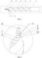
Fig. 1 schematically depicts a structure of a spiral step twist drill bit according to an embodiment of the present disclosure; -
Fig. 2 schematically depicts a tip of a cutting portion of the spiral step twist drill bit according to an embodiment of the present disclosure; -
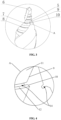
Fig. 3 schematically depicts a tip of a cutting portion of a spiral step twist drill bit with a spiral chip removal groove according to an embodiment of the present disclosure; and -
Fig. 4 is an enlarged view of part A inFig. 3 . - In the drawings, 1, shank; 2, cutting portion; 3, spiral flute; 4, body clearance; 5, cutting edge; 6, chisel edge; 7, flank face; 8, spiral cutting groove; 9, first edge; 10, second edge; 11, first annular surface; 12, second annular surface; 13, spiral transition step; and 14, spiral chip removal groove.
- Technical solutions of the present disclosure will be clearly and completely described below with reference to the embodiments and accompanying drawings.
- As shown in
Figs. 1-4 , a spiral step twist drill bit includes ashank 1 and acutting portion 2. Thecutting portion 2 is provided with aspiral flute 3 and abody clearance 4. A tip of thecutting portion 2 is provided with achisel edge 6 and acutting edge 5. Aflank face 7 connected to thecutting edge 5 is provided with aspiral cutting groove 8. A spiral direction of thespiral cutting groove 8 is the same as a spiral direction of thespiral flute 3. A slope of thespiral cutting groove 8 is the same as a slope of theflank face 7. Thespiral cutting groove 8 is configured to divide thecutting edge 5 into multiple segments to form multiplefirst edges 9 andsecond edges 10. Thespiral cutting groove 8 is configured to divide theflank face 7 into a plurality of firstannular surfaces 11 and a plurality of secondannular surfaces 12, where each of the firstannular surfaces 11 is perpendicular to one of the secondannular surfaces 12. Thefirst edges 9 are respectively located on the firstannular surfaces 11. Thesecond edges 10 are respectively located on the secondannular surfaces 12. - Specifically, referring to
Fig. 2 , thefirst edges 9 and thesecond edges 10 has a spiral step structure. The spiral direction of thespiral cutting groove 8 is the same as a rotating direction of the spiral step twist drill bit. Therefore, during drilling round holes in a workpiece, the workpiece is subjected to a greater centrifugal force, which is energyefficient for the spiral step twist drill bit. In addition, compared to the existing parallel step structure, the spiral step structure defines a high point and a low point at the same step, such that there is a height difference between two adjacent steps within the same pitch. Therefore, multiple steps of the spiral steps structure can realize segmental cutting, which is more labor-saving and has faster cutting speed. After a first step has performed cutting, the spiral step structure continues to cut inward with a small force, greatly increasing a cutting speed and reducing a force, such that cut longer distances can be cut with the same force. - In an embodiment, the
first edges 9 and thesecond edges 10 enable a segmented cutting for the workpiece. - In an embodiment, since a diameter of the
cutting edge 5 is gradually increased from the tip of thecutting portion 2 to theshank 1, after thespiral cutting groove 8 divides thecutting edge 5 into multiple segments to form new multiplefirst edges 9 andsecond edges 10, a diameter of thefirst edges 9 and that of thesecond edges 10 are increased from the tip of thecutting portion 2 to theshank 1. - In an embodiment, the
spiral cutting groove 8 has a varying pitch, that is, the pitch of thespiral cutting groove 8 is variable from the tip of thecutting portion 2 towards theshank 1. - In an embodiment, a pitch of the
spiral cutting groove 8 increases from the tip of thecutting portion 2 towards theshank 1. An increment rate of the pitch is 1.2-1.5. Within the increment rate, a triangular edge, which is formed after cutting by afirst edge 9 and asecond edge 10, can be cut entirely by a next adjacentfirst edge 9 and a next adjacentsecond edge 10 during a next cutting. - The pitch of the
spiral cutting groove 8 increases from the tip of thecutting portion 2 towards theshank 1, resulting that a step length of the spiral step structure formed by afirst edge 9 and asecond edge 10 increases from the tip of thecutting portion 2 towards theshank 1, that is, a length of thefirst edge 9 increases from the tip of thecutting portion 2 towards theshank 1. Specifically, a length of afirst edge 9 firstly contacting the workpiece is shorter. In consequence, during drilling round holes in the workpiece, thefirst edge 9 firstly contacting the workpiece and asecond edge 10 firstly contacting the workpiece both have a smaller contact area with the workpiece, and are subject to less resistance, thereby making a faster and smoother drilling. - In addition, since the pitch of the
spiral cutting groove 8 increases, the step length of the spiral step structure increases, that is, the length of thefirst edge 9 increases. During drilling round holes in the workpiece, afirst edge 9 having a greater length and a correspondingsecond edge 10 spend more time in a position closer to the largest hole diameter of a product (i.e., a position closer to a hole diameter of a finished size), so as to better grind the hole wall to allow better smoothness and roundness. - In an embodiment, referring to
Fig. 2 , aspiral transition step 13 is provided at an end of each of the firstannular surfaces 11 away from a corresponding secondannular surface 12. A spiral direction of thespiral transition step 13 is the same as that of thespiral flute 3. In this embodiment, thespiral transition step 13 is provided at the end of each of the firstannular surface 11 away from the corresponding secondannular surface 12, i.e., thespiral transition step 13 is located at an end of each of the firstannular surface 11 which is connected to a last secondannular surface 12, such that aspiral transition step 13 is provided between each of two adjacent spiral step structures for transition. Thespiral transition step 13 plays a cushioning role when the spiral step structure becomes larger. During use, thespiral transition step 13 reduces a stop feeling and sudden drop feeling which occurs when the spiral step structure performs segmented cutting. - In an embodiment, a size of the
spiral transition step 13 increases from the tip of the cuttingportion 2 towards theshank 1, making a smoother transition between the firstannular surface 11 and the last secondannular surface 12. Thereby, a drilling is smoother, which improves a cutting speed. - In an embodiment, referring to
Figs. 3-4 , a spiralchip removal groove 14 is provided at a connection between each of the firstannular surfaces 11 and a corresponding secondannular surface 12. A spiral direction of the spiralchip removal groove 14 is the same as the spiral direction of thespiral flute 3. Specifically, as shown inFigs. 3-4 , the spiralchip removal groove 14 is located at a right-angle recess formed by each of the firstannular surface 11 and a corresponding secondannular surface 12, and no spiralchip removal groove 14 is provided at a right-angle protrusion formed by each of the secondannular surfaces 12 and a next firstannular surface 11. - Due to the spiral
chip removal groove 14, chips cut off from the workpiece can be discharged along the spiralchip removal groove 14 when the spiral step twist drill bit drills a round hole in the workpiece. Thus, the drilling frees from stopping several times to clean the chips from the round hole of the workpiece. - Specifically, the spiral
chip removal groove 14 is partially shown inFig. 3 . The connection between each of the firstannular surface 11 and a corresponding secondannular surface 12 is provided with a spiralchip removal groove 14, such that the chips cut off from the workpiece can be discharged to outside along the spiralchip removal groove 14. - Described above are merely illustrative of the disclosure, and are not intended to limit the disclosure. It should be understood that any changes, replacements and modifications made by those skilled in the art based on the content disclosed herein without departing from the scope of the disclosure shall fall within the scope of the present disclosure defined by the appended claims.
Claims (4)
- A spiral step twist drill bit, comprising:a shank (1); anda cutting portion (2);wherein the cutting portion (2) is provided with a spiral flute (3) and a body clearance (4); a tip of the cutting portion (2) is provided with a chisel edge (6) and a cutting edge (5); a flank face (7) connected to the cutting edge (5) is provided with a spiral cutting groove (8); a spiral direction of the spiral cutting groove (8) is the same as a spiral direction of the spiral flute (3); a slope of the spiral cutting groove (8) is the same as a slope of the flank face (7); the spiral cutting groove (8) is configured to divide the cutting edge (5) into a plurality of segments to form a plurality of first edges (9) and a plurality of second edges (10); the spiral cutting groove (8) is configured to divide the flank face (7) into a plurality of first annular surfaces (11) and a plurality of second annular surfaces (12), wherein each of the first annular surfaces (11) is perpendicular to one of the second annular surfaces (12); the plurality of first edges (9) are respectively located on the plurality of first annular surfaces (11); and the plurality of second edges (10) are respectively located on the plurality of second annular surfaces (12);characterized in that a spiral chip removal groove (14) is provided at a connection between each of the plurality of first annular surfaces (11) and a corresponding second annular surfaces (12); and a spiral direction of the spiral chip removal groove (14) is the same as the spiral direction of the spiral flute (3).
- The spiral step twist drill bit according to claim 1, characterized in that the spiral cutting groove (8) has a varyingpitch.
- The spiral step twist drill bit according to claim 1, characterized in thata pitch of the spiral cutting groove (8) increases from the tip of the cutting portion (2) towards the shank (1).
- The spiral step twist drill bit according to claim 3, characterized in that an increment rate of the pitch of the spiral cutting groove (8) is 1.2-1.5.
Applications Claiming Priority (1)
| Application Number | Priority Date | Filing Date | Title |
|---|---|---|---|
| CN202121312367.9U CN214720850U (en) | 2021-06-11 | 2021-06-11 | Spiral stepped drill point twist drill |
Publications (3)
| Publication Number | Publication Date |
|---|---|
| EP4101566A1 EP4101566A1 (en) | 2022-12-14 |
| EP4101566C0 EP4101566C0 (en) | 2024-07-03 |
| EP4101566B1 true EP4101566B1 (en) | 2024-07-03 |
Family
ID=78629704
Family Applications (1)
| Application Number | Title | Priority Date | Filing Date |
|---|---|---|---|
| EP22178374.9A Active EP4101566B1 (en) | 2021-06-11 | 2022-06-10 | Spiral step twist drill bit |
Country Status (6)
| Country | Link |
|---|---|
| US (1) | US11839921B2 (en) |
| EP (1) | EP4101566B1 (en) |
| CN (1) | CN214720850U (en) |
| DE (1) | DE202022100029U1 (en) |
| ES (1) | ES2995025T3 (en) |
| PL (1) | PL4101566T3 (en) |
Families Citing this family (4)
| Publication number | Priority date | Publication date | Assignee | Title |
|---|---|---|---|---|
| CN115740577B (en) * | 2022-11-18 | 2025-11-11 | 丹阳凯亿源工具有限公司 | Multi-layer step drill tip twist drill |
| US20240082929A1 (en) | 2022-11-18 | 2024-03-14 | Danyang Kaiyiyuan Tools Co., Ltd. | Twist drill with multi-step drill point |
| CN115740579B (en) * | 2022-11-18 | 2025-11-25 | 丹阳凯亿源工具有限公司 | A multi-layer stepped head drilling composite tap |
| CN219616777U (en) * | 2023-01-28 | 2023-09-01 | 江晓猛 | Asymmetric step-by-step cutting step drill |
Family Cites Families (10)
| Publication number | Priority date | Publication date | Assignee | Title |
|---|---|---|---|---|
| GB155004A (en) * | 1919-09-06 | 1920-12-06 | Thomas Robertson | An improved spirally fluted drill |
| CN1375373A (en) * | 2001-03-21 | 2002-10-23 | 周安善 | Efficient universal twist drill with two milling cutter edges and its sharpening method |
| US8029215B2 (en) * | 2007-01-05 | 2011-10-04 | Greenlee Textron Inc. | Spiral drill bit and method of forming same |
| US9308589B2 (en) * | 2011-12-27 | 2016-04-12 | Sumitomo Electric Industries, Ltd. | Drill |
| CN102581355A (en) * | 2012-03-27 | 2012-07-18 | 周安善 | Twist drill for drilling precision holes on high-strength and high-hardness alloy materials |
| US11007583B2 (en) * | 2016-02-14 | 2021-05-18 | Hongjia Wang | Twist drill |
| CN205551557U (en) | 2016-02-14 | 2016-09-07 | 上海钰工机电有限公司 | High -efficient fluted drill of layering drilling |
| EP4227031A1 (en) | 2016-02-14 | 2023-08-16 | Tec-Spiral Enterprises Tools Co., Ltd. | High efficiency step-structured twist drill |
| US10207335B2 (en) * | 2017-07-22 | 2019-02-19 | Picote Solutions Inc. | Device for opening connection to lined pipe |
| CN110802259B (en) * | 2019-11-28 | 2021-07-06 | 上海钰工机电有限公司 | twist drill |
-
2021
- 2021-06-11 CN CN202121312367.9U patent/CN214720850U/en active Active
-
2022
- 2022-01-03 DE DE202022100029.8U patent/DE202022100029U1/en active Active
- 2022-06-10 ES ES22178374T patent/ES2995025T3/en active Active
- 2022-06-10 EP EP22178374.9A patent/EP4101566B1/en active Active
- 2022-06-10 US US17/837,215 patent/US11839921B2/en active Active
- 2022-06-10 PL PL22178374.9T patent/PL4101566T3/en unknown
Also Published As
| Publication number | Publication date |
|---|---|
| US11839921B2 (en) | 2023-12-12 |
| EP4101566C0 (en) | 2024-07-03 |
| PL4101566T3 (en) | 2025-01-07 |
| CN214720850U (en) | 2021-11-16 |
| US20220362863A1 (en) | 2022-11-17 |
| EP4101566A1 (en) | 2022-12-14 |
| DE202022100029U1 (en) | 2022-01-14 |
| ES2995025T3 (en) | 2025-02-05 |
Similar Documents
| Publication | Publication Date | Title |
|---|---|---|
| EP4101566A1 (en) | Spiral step twist drill bit | |
| WO2021103393A1 (en) | Twist drill | |
| US20200094331A1 (en) | Twist drill | |
| CN103128346B (en) | There is the fluted drill that helical form cuts rear knife face | |
| CN116493651A (en) | A special cutting tool for helical milling holes in composite materials | |
| CN107398599B (en) | Super-precision reamer | |
| CN214488963U (en) | Drill bit with chip breaker groove three-edge drill tip | |
| CN216325380U (en) | Efficient drilling reamer | |
| JP3111276U (en) | Chamfering end mill | |
| CN116061263B (en) | A drill bit for soft materials | |
| CN210702770U (en) | Milling cutter with end chip grooves | |
| CN202356686U (en) | Left-handed straight shank twist drill with three edges | |
| CN213969319U (en) | Chamfering tool | |
| CN223146071U (en) | Deep hole drilling bit suitable for MQL cooling | |
| CN220882727U (en) | Straight flute woodworking milling cutter | |
| CN206732226U (en) | Compound drilling and milling cutter | |
| CN222199035U (en) | Drilling and milling cutter for efficient taper hole machining | |
| CN217492805U (en) | twist drill | |
| CN217095847U (en) | Four-plane SR type high-precision drill bit | |
| CN223071695U (en) | Drill bit and processing equipment | |
| CN223876140U (en) | Drilling reamer | |
| CN105252089A (en) | Precision cutting tool for high-hardness die steel | |
| CN220547888U (en) | High-performance drilling reamer | |
| CN224088028U (en) | An anti-sway internal cooling step drill with guide ridge | |
| CN221269779U (en) | Corrugated milling cutter |
Legal Events
| Date | Code | Title | Description |
|---|---|---|---|
| PUAI | Public reference made under article 153(3) epc to a published international application that has entered the european phase |
Free format text: ORIGINAL CODE: 0009012 |
|
| STAA | Information on the status of an ep patent application or granted ep patent |
Free format text: STATUS: REQUEST FOR EXAMINATION WAS MADE |
|
| 17P | Request for examination filed |
Effective date: 20220610 |
|
| AK | Designated contracting states |
Kind code of ref document: A1 Designated state(s): AL AT BE BG CH CY CZ DE DK EE ES FI FR GB GR HR HU IE IS IT LI LT LU LV MC MK MT NL NO PL PT RO RS SE SI SK SM TR |
|
| STAA | Information on the status of an ep patent application or granted ep patent |
Free format text: STATUS: EXAMINATION IS IN PROGRESS |
|
| 17Q | First examination report despatched |
Effective date: 20230928 |
|
| GRAP | Despatch of communication of intention to grant a patent |
Free format text: ORIGINAL CODE: EPIDOSNIGR1 |
|
| STAA | Information on the status of an ep patent application or granted ep patent |
Free format text: STATUS: GRANT OF PATENT IS INTENDED |
|
| INTG | Intention to grant announced |
Effective date: 20240415 |
|
| GRAS | Grant fee paid |
Free format text: ORIGINAL CODE: EPIDOSNIGR3 |
|
| GRAA | (expected) grant |
Free format text: ORIGINAL CODE: 0009210 |
|
| STAA | Information on the status of an ep patent application or granted ep patent |
Free format text: STATUS: THE PATENT HAS BEEN GRANTED |
|
| AK | Designated contracting states |
Kind code of ref document: B1 Designated state(s): AL AT BE BG CH CY CZ DE DK EE ES FI FR GB GR HR HU IE IS IT LI LT LU LV MC MK MT NL NO PL PT RO RS SE SI SK SM TR |
|
| REG | Reference to a national code |
Ref country code: CH Ref legal event code: EP |
|
| REG | Reference to a national code |
Ref country code: DE Ref legal event code: R096 Ref document number: 602022004266 Country of ref document: DE |
|
| U01 | Request for unitary effect filed |
Effective date: 20240708 |
|
| U07 | Unitary effect registered |
Designated state(s): AT BE BG DE DK EE FI FR IT LT LU LV MT NL PT SE SI Effective date: 20240718 |
|
| PG25 | Lapsed in a contracting state [announced via postgrant information from national office to epo] |
Ref country code: NO Free format text: LAPSE BECAUSE OF FAILURE TO SUBMIT A TRANSLATION OF THE DESCRIPTION OR TO PAY THE FEE WITHIN THE PRESCRIBED TIME-LIMIT Effective date: 20241003 |
|
| PG25 | Lapsed in a contracting state [announced via postgrant information from national office to epo] |
Ref country code: GR Free format text: LAPSE BECAUSE OF FAILURE TO SUBMIT A TRANSLATION OF THE DESCRIPTION OR TO PAY THE FEE WITHIN THE PRESCRIBED TIME-LIMIT Effective date: 20241004 |
|
| PG25 | Lapsed in a contracting state [announced via postgrant information from national office to epo] |
Ref country code: IS Free format text: LAPSE BECAUSE OF FAILURE TO SUBMIT A TRANSLATION OF THE DESCRIPTION OR TO PAY THE FEE WITHIN THE PRESCRIBED TIME-LIMIT Effective date: 20241103 |
|
| PG25 | Lapsed in a contracting state [announced via postgrant information from national office to epo] |
Ref country code: CZ Free format text: LAPSE BECAUSE OF FAILURE TO SUBMIT A TRANSLATION OF THE DESCRIPTION OR TO PAY THE FEE WITHIN THE PRESCRIBED TIME-LIMIT Effective date: 20240703 Ref country code: HR Free format text: LAPSE BECAUSE OF FAILURE TO SUBMIT A TRANSLATION OF THE DESCRIPTION OR TO PAY THE FEE WITHIN THE PRESCRIBED TIME-LIMIT Effective date: 20240703 |
|
| PG25 | Lapsed in a contracting state [announced via postgrant information from national office to epo] |
Ref country code: RS Free format text: LAPSE BECAUSE OF FAILURE TO SUBMIT A TRANSLATION OF THE DESCRIPTION OR TO PAY THE FEE WITHIN THE PRESCRIBED TIME-LIMIT Effective date: 20241003 |
|
| PG25 | Lapsed in a contracting state [announced via postgrant information from national office to epo] |
Ref country code: RS Free format text: LAPSE BECAUSE OF FAILURE TO SUBMIT A TRANSLATION OF THE DESCRIPTION OR TO PAY THE FEE WITHIN THE PRESCRIBED TIME-LIMIT Effective date: 20241003 Ref country code: NO Free format text: LAPSE BECAUSE OF FAILURE TO SUBMIT A TRANSLATION OF THE DESCRIPTION OR TO PAY THE FEE WITHIN THE PRESCRIBED TIME-LIMIT Effective date: 20241003 Ref country code: IS Free format text: LAPSE BECAUSE OF FAILURE TO SUBMIT A TRANSLATION OF THE DESCRIPTION OR TO PAY THE FEE WITHIN THE PRESCRIBED TIME-LIMIT Effective date: 20241103 Ref country code: HR Free format text: LAPSE BECAUSE OF FAILURE TO SUBMIT A TRANSLATION OF THE DESCRIPTION OR TO PAY THE FEE WITHIN THE PRESCRIBED TIME-LIMIT Effective date: 20240703 Ref country code: GR Free format text: LAPSE BECAUSE OF FAILURE TO SUBMIT A TRANSLATION OF THE DESCRIPTION OR TO PAY THE FEE WITHIN THE PRESCRIBED TIME-LIMIT Effective date: 20241004 Ref country code: CZ Free format text: LAPSE BECAUSE OF FAILURE TO SUBMIT A TRANSLATION OF THE DESCRIPTION OR TO PAY THE FEE WITHIN THE PRESCRIBED TIME-LIMIT Effective date: 20240703 |
|
| REG | Reference to a national code |
Ref country code: ES Ref legal event code: FG2A Ref document number: 2995025 Country of ref document: ES Kind code of ref document: T3 Effective date: 20250205 |
|
| PG25 | Lapsed in a contracting state [announced via postgrant information from national office to epo] |
Ref country code: SM Free format text: LAPSE BECAUSE OF FAILURE TO SUBMIT A TRANSLATION OF THE DESCRIPTION OR TO PAY THE FEE WITHIN THE PRESCRIBED TIME-LIMIT Effective date: 20240703 |
|
| PG25 | Lapsed in a contracting state [announced via postgrant information from national office to epo] |
Ref country code: SK Free format text: LAPSE BECAUSE OF FAILURE TO SUBMIT A TRANSLATION OF THE DESCRIPTION OR TO PAY THE FEE WITHIN THE PRESCRIBED TIME-LIMIT Effective date: 20240703 |
|
| PLBE | No opposition filed within time limit |
Free format text: ORIGINAL CODE: 0009261 |
|
| STAA | Information on the status of an ep patent application or granted ep patent |
Free format text: STATUS: NO OPPOSITION FILED WITHIN TIME LIMIT |
|
| 26N | No opposition filed |
Effective date: 20250404 |
|
| U20 | Renewal fee for the european patent with unitary effect paid |
Year of fee payment: 4 Effective date: 20250515 |
|
| PGFP | Annual fee paid to national office [announced via postgrant information from national office to epo] |
Ref country code: ES Payment date: 20250714 Year of fee payment: 4 |
|
| REG | Reference to a national code |
Ref country code: CH Ref legal event code: H13 Free format text: ST27 STATUS EVENT CODE: U-0-0-H10-H13 (AS PROVIDED BY THE NATIONAL OFFICE) Effective date: 20260127 |
|
| PG25 | Lapsed in a contracting state [announced via postgrant information from national office to epo] |
Ref country code: MC Free format text: LAPSE BECAUSE OF FAILURE TO SUBMIT A TRANSLATION OF THE DESCRIPTION OR TO PAY THE FEE WITHIN THE PRESCRIBED TIME-LIMIT Effective date: 20240703 |
|
| PG25 | Lapsed in a contracting state [announced via postgrant information from national office to epo] |
Ref country code: IE Free format text: LAPSE BECAUSE OF NON-PAYMENT OF DUE FEES Effective date: 20250610 |
|
| PG25 | Lapsed in a contracting state [announced via postgrant information from national office to epo] |
Ref country code: RO Free format text: LAPSE BECAUSE OF FAILURE TO SUBMIT A TRANSLATION OF THE DESCRIPTION OR TO PAY THE FEE WITHIN THE PRESCRIBED TIME-LIMIT Effective date: 20240703 |
|
| PG25 | Lapsed in a contracting state [announced via postgrant information from national office to epo] |
Ref country code: CH Free format text: LAPSE BECAUSE OF NON-PAYMENT OF DUE FEES Effective date: 20250630 |
|
| U20 | Renewal fee for the european patent with unitary effect paid |
Year of fee payment: 5 Effective date: 20260413 |
|
| PGFP | Annual fee paid to national office [announced via postgrant information from national office to epo] |
Ref country code: GB Payment date: 20260413 Year of fee payment: 5 Ref country code: PL Payment date: 20260603 Year of fee payment: 5 |
|
| PG25 | Lapsed in a contracting state [announced via postgrant information from national office to epo] |
Ref country code: CY Free format text: LAPSE BECAUSE OF FAILURE TO SUBMIT A TRANSLATION OF THE DESCRIPTION OR TO PAY THE FEE WITHIN THE PRESCRIBED TIME-LIMIT Effective date: 20240703 |