EP4101474A1 - Systems and methods for moveably supporting an ultraviolet (uv) light lamp within an enclosed space - Google Patents
Systems and methods for moveably supporting an ultraviolet (uv) light lamp within an enclosed space Download PDFInfo
- Publication number
- EP4101474A1 EP4101474A1 EP22176736.1A EP22176736A EP4101474A1 EP 4101474 A1 EP4101474 A1 EP 4101474A1 EP 22176736 A EP22176736 A EP 22176736A EP 4101474 A1 EP4101474 A1 EP 4101474A1
- Authority
- EP
- European Patent Office
- Prior art keywords
- disinfecting system
- lamp
- articulating arm
- enclosed space
- internal cabin
- Prior art date
- Legal status (The legal status is an assumption and is not a legal conclusion. Google has not performed a legal analysis and makes no representation as to the accuracy of the status listed.)
- Pending
Links
- 238000000034 method Methods 0.000 title abstract description 23
- 230000000249 desinfective effect Effects 0.000 claims abstract description 107
- 238000004659 sterilization and disinfection Methods 0.000 claims abstract description 37
- 125000006850 spacer group Chemical group 0.000 claims description 20
- 230000004913 activation Effects 0.000 description 19
- 230000000712 assembly Effects 0.000 description 10
- 238000000429 assembly Methods 0.000 description 10
- 230000008878 coupling Effects 0.000 description 6
- 238000010168 coupling process Methods 0.000 description 6
- 238000005859 coupling reaction Methods 0.000 description 6
- 230000029058 respiratory gaseous exchange Effects 0.000 description 5
- 238000010586 diagram Methods 0.000 description 2
- 239000000463 material Substances 0.000 description 2
- 230000007246 mechanism Effects 0.000 description 2
- 238000011012 sanitization Methods 0.000 description 2
- 238000001228 spectrum Methods 0.000 description 2
- 239000003381 stabilizer Substances 0.000 description 2
- 241000894006 Bacteria Species 0.000 description 1
- 241000700605 Viruses Species 0.000 description 1
- 229910052782 aluminium Inorganic materials 0.000 description 1
- XAGFODPZIPBFFR-UHFFFAOYSA-N aluminium Chemical compound [Al] XAGFODPZIPBFFR-UHFFFAOYSA-N 0.000 description 1
- QVGXLLKOCUKJST-UHFFFAOYSA-N atomic oxygen Chemical compound [O] QVGXLLKOCUKJST-UHFFFAOYSA-N 0.000 description 1
- 238000004891 communication Methods 0.000 description 1
- 230000003137 locomotive effect Effects 0.000 description 1
- 229910052751 metal Inorganic materials 0.000 description 1
- 239000002184 metal Substances 0.000 description 1
- 238000012986 modification Methods 0.000 description 1
- 230000004048 modification Effects 0.000 description 1
- 229910052760 oxygen Inorganic materials 0.000 description 1
- 239000001301 oxygen Substances 0.000 description 1
- 244000052769 pathogen Species 0.000 description 1
- 230000004044 response Effects 0.000 description 1
- 230000007704 transition Effects 0.000 description 1
Images


Classifications
-
- A—HUMAN NECESSITIES
- A61—MEDICAL OR VETERINARY SCIENCE; HYGIENE
- A61L—METHODS OR APPARATUS FOR STERILISING MATERIALS OR OBJECTS IN GENERAL; DISINFECTION, STERILISATION OR DEODORISATION OF AIR; CHEMICAL ASPECTS OF BANDAGES, DRESSINGS, ABSORBENT PADS OR SURGICAL ARTICLES; MATERIALS FOR BANDAGES, DRESSINGS, ABSORBENT PADS OR SURGICAL ARTICLES
- A61L2/00—Methods or apparatus for disinfecting or sterilising materials or objects other than foodstuffs or contact lenses; Accessories therefor
- A61L2/02—Methods or apparatus for disinfecting or sterilising materials or objects other than foodstuffs or contact lenses; Accessories therefor using physical phenomena
- A61L2/08—Radiation
- A61L2/10—Ultra-violet radiation
-
- A—HUMAN NECESSITIES
- A61—MEDICAL OR VETERINARY SCIENCE; HYGIENE
- A61L—METHODS OR APPARATUS FOR STERILISING MATERIALS OR OBJECTS IN GENERAL; DISINFECTION, STERILISATION OR DEODORISATION OF AIR; CHEMICAL ASPECTS OF BANDAGES, DRESSINGS, ABSORBENT PADS OR SURGICAL ARTICLES; MATERIALS FOR BANDAGES, DRESSINGS, ABSORBENT PADS OR SURGICAL ARTICLES
- A61L2/00—Methods or apparatus for disinfecting or sterilising materials or objects other than foodstuffs or contact lenses; Accessories therefor
- A61L2/24—Apparatus using programmed or automatic operation
-
- A—HUMAN NECESSITIES
- A61—MEDICAL OR VETERINARY SCIENCE; HYGIENE
- A61L—METHODS OR APPARATUS FOR STERILISING MATERIALS OR OBJECTS IN GENERAL; DISINFECTION, STERILISATION OR DEODORISATION OF AIR; CHEMICAL ASPECTS OF BANDAGES, DRESSINGS, ABSORBENT PADS OR SURGICAL ARTICLES; MATERIALS FOR BANDAGES, DRESSINGS, ABSORBENT PADS OR SURGICAL ARTICLES
- A61L2/00—Methods or apparatus for disinfecting or sterilising materials or objects other than foodstuffs or contact lenses; Accessories therefor
- A61L2/26—Accessories or devices or components used for biocidal treatment
-
- B—PERFORMING OPERATIONS; TRANSPORTING
- B64—AIRCRAFT; AVIATION; COSMONAUTICS
- B64D—EQUIPMENT FOR FITTING IN OR TO AIRCRAFT; FLIGHT SUITS; PARACHUTES; ARRANGEMENTS OR MOUNTING OF POWER PLANTS OR PROPULSION TRANSMISSIONS IN AIRCRAFT
- B64D11/00—Passenger or crew accommodation; Flight-deck installations not otherwise provided for
- B64D11/003—Stowage devices for passengers' personal luggage
-
- B—PERFORMING OPERATIONS; TRANSPORTING
- B64—AIRCRAFT; AVIATION; COSMONAUTICS
- B64D—EQUIPMENT FOR FITTING IN OR TO AIRCRAFT; FLIGHT SUITS; PARACHUTES; ARRANGEMENTS OR MOUNTING OF POWER PLANTS OR PROPULSION TRANSMISSIONS IN AIRCRAFT
- B64D11/00—Passenger or crew accommodation; Flight-deck installations not otherwise provided for
- B64D11/06—Arrangements of seats, or adaptations or details specially adapted for aircraft seats
- B64D11/0646—Seats characterised by special features of stationary arms, foot or head rests
-
- B—PERFORMING OPERATIONS; TRANSPORTING
- B64—AIRCRAFT; AVIATION; COSMONAUTICS
- B64D—EQUIPMENT FOR FITTING IN OR TO AIRCRAFT; FLIGHT SUITS; PARACHUTES; ARRANGEMENTS OR MOUNTING OF POWER PLANTS OR PROPULSION TRANSMISSIONS IN AIRCRAFT
- B64D13/00—Arrangements or adaptations of air-treatment apparatus for aircraft crew or passengers, or freight space, or structural parts of the aircraft
- B64D13/06—Arrangements or adaptations of air-treatment apparatus for aircraft crew or passengers, or freight space, or structural parts of the aircraft the air being conditioned
-
- B—PERFORMING OPERATIONS; TRANSPORTING
- B64—AIRCRAFT; AVIATION; COSMONAUTICS
- B64D—EQUIPMENT FOR FITTING IN OR TO AIRCRAFT; FLIGHT SUITS; PARACHUTES; ARRANGEMENTS OR MOUNTING OF POWER PLANTS OR PROPULSION TRANSMISSIONS IN AIRCRAFT
- B64D47/00—Equipment not otherwise provided for
- B64D47/02—Arrangements or adaptations of signal or lighting devices
-
- B—PERFORMING OPERATIONS; TRANSPORTING
- B64—AIRCRAFT; AVIATION; COSMONAUTICS
- B64F—GROUND OR AIRCRAFT-CARRIER-DECK INSTALLATIONS SPECIALLY ADAPTED FOR USE IN CONNECTION WITH AIRCRAFT; DESIGNING, MANUFACTURING, ASSEMBLING, CLEANING, MAINTAINING OR REPAIRING AIRCRAFT, NOT OTHERWISE PROVIDED FOR; HANDLING, TRANSPORTING, TESTING OR INSPECTING AIRCRAFT COMPONENTS, NOT OTHERWISE PROVIDED FOR
- B64F5/00—Designing, manufacturing, assembling, cleaning, maintaining or repairing aircraft, not otherwise provided for; Handling, transporting, testing or inspecting aircraft components, not otherwise provided for
- B64F5/30—Cleaning aircraft
-
- A—HUMAN NECESSITIES
- A61—MEDICAL OR VETERINARY SCIENCE; HYGIENE
- A61L—METHODS OR APPARATUS FOR STERILISING MATERIALS OR OBJECTS IN GENERAL; DISINFECTION, STERILISATION OR DEODORISATION OF AIR; CHEMICAL ASPECTS OF BANDAGES, DRESSINGS, ABSORBENT PADS OR SURGICAL ARTICLES; MATERIALS FOR BANDAGES, DRESSINGS, ABSORBENT PADS OR SURGICAL ARTICLES
- A61L2202/00—Aspects relating to methods or apparatus for disinfecting or sterilising materials or objects
- A61L2202/10—Apparatus features
- A61L2202/11—Apparatus for generating biocidal substances, e.g. vaporisers, UV lamps
-
- A—HUMAN NECESSITIES
- A61—MEDICAL OR VETERINARY SCIENCE; HYGIENE
- A61L—METHODS OR APPARATUS FOR STERILISING MATERIALS OR OBJECTS IN GENERAL; DISINFECTION, STERILISATION OR DEODORISATION OF AIR; CHEMICAL ASPECTS OF BANDAGES, DRESSINGS, ABSORBENT PADS OR SURGICAL ARTICLES; MATERIALS FOR BANDAGES, DRESSINGS, ABSORBENT PADS OR SURGICAL ARTICLES
- A61L2202/00—Aspects relating to methods or apparatus for disinfecting or sterilising materials or objects
- A61L2202/10—Apparatus features
- A61L2202/14—Means for controlling sterilisation processes, data processing, presentation and storage means, e.g. sensors, controllers, programs
-
- A—HUMAN NECESSITIES
- A61—MEDICAL OR VETERINARY SCIENCE; HYGIENE
- A61L—METHODS OR APPARATUS FOR STERILISING MATERIALS OR OBJECTS IN GENERAL; DISINFECTION, STERILISATION OR DEODORISATION OF AIR; CHEMICAL ASPECTS OF BANDAGES, DRESSINGS, ABSORBENT PADS OR SURGICAL ARTICLES; MATERIALS FOR BANDAGES, DRESSINGS, ABSORBENT PADS OR SURGICAL ARTICLES
- A61L2202/00—Aspects relating to methods or apparatus for disinfecting or sterilising materials or objects
- A61L2202/10—Apparatus features
- A61L2202/15—Biocide distribution means, e.g. nozzles, pumps, manifolds, fans, baffles, sprayers
-
- A—HUMAN NECESSITIES
- A61—MEDICAL OR VETERINARY SCIENCE; HYGIENE
- A61L—METHODS OR APPARATUS FOR STERILISING MATERIALS OR OBJECTS IN GENERAL; DISINFECTION, STERILISATION OR DEODORISATION OF AIR; CHEMICAL ASPECTS OF BANDAGES, DRESSINGS, ABSORBENT PADS OR SURGICAL ARTICLES; MATERIALS FOR BANDAGES, DRESSINGS, ABSORBENT PADS OR SURGICAL ARTICLES
- A61L2202/00—Aspects relating to methods or apparatus for disinfecting or sterilising materials or objects
- A61L2202/10—Apparatus features
- A61L2202/16—Mobile applications, e.g. portable devices, trailers, devices mounted on vehicles
-
- A—HUMAN NECESSITIES
- A61—MEDICAL OR VETERINARY SCIENCE; HYGIENE
- A61L—METHODS OR APPARATUS FOR STERILISING MATERIALS OR OBJECTS IN GENERAL; DISINFECTION, STERILISATION OR DEODORISATION OF AIR; CHEMICAL ASPECTS OF BANDAGES, DRESSINGS, ABSORBENT PADS OR SURGICAL ARTICLES; MATERIALS FOR BANDAGES, DRESSINGS, ABSORBENT PADS OR SURGICAL ARTICLES
- A61L2202/00—Aspects relating to methods or apparatus for disinfecting or sterilising materials or objects
- A61L2202/20—Targets to be treated
- A61L2202/25—Rooms in buildings, passenger compartments
-
- B—PERFORMING OPERATIONS; TRANSPORTING
- B64—AIRCRAFT; AVIATION; COSMONAUTICS
- B64D—EQUIPMENT FOR FITTING IN OR TO AIRCRAFT; FLIGHT SUITS; PARACHUTES; ARRANGEMENTS OR MOUNTING OF POWER PLANTS OR PROPULSION TRANSMISSIONS IN AIRCRAFT
- B64D13/00—Arrangements or adaptations of air-treatment apparatus for aircraft crew or passengers, or freight space, or structural parts of the aircraft
- B64D13/06—Arrangements or adaptations of air-treatment apparatus for aircraft crew or passengers, or freight space, or structural parts of the aircraft the air being conditioned
- B64D2013/0603—Environmental Control Systems
Definitions
- Examples of the present disclosure generally relate to systems and methods for sanitizing surfaces within an enclosed space, such an internal cabin of a commercial aircraft, and more particularly to systems and methods for moveably supporting an ultraviolet (UV) light lamp within the enclosed space.
- an enclosed space such an internal cabin of a commercial aircraft
- UV ultraviolet
- UV light disinfection is more effective when a UV light emitter is closer to a surface that is to be disinfected.
- a UV light emitter may be spaced apart from an area or space that is to be disinfected at a relatively long distance.
- the UV light emitter typically needs to be of sufficient power to effectively disinfect the target area or space.
- the power typically needed for the UV light emitter is also generally increased.
- effective UV light disinfection within a particular setting may typically require an increased amount of time and power.
- the disinfecting system includes an articulating arm moveably coupled to a structure within the enclosed space.
- An ultraviolet (UV) lamp is coupled to the articulating arm.
- the UV lamp is configured to emit UV light toward a disinfection zone within the enclosed space.
- the articulating arm allows the UV lamp to move relative to the disinfection zone.
- the articulating arm includes one or more pivot joints.
- one or more dampers are coupled to the one or more pivot joints.
- the articulating arm allows the UV lamp to move between a stowed position and a deployed position.
- a latch is coupled to the structure and the articulating arm.
- the latch is selectively moveable between a locked position and an unlocked position.
- an activation member is configured to control the latch.
- the enclosed space is an internal cabin of a vehicle.
- the structure is a spacer panel within the internal cabin.
- the spacer panel includes a cavity. At least a portion of the articulating is within the cavity in a stowed position.
- the structure is a passenger service unit (PSU) within the internal cabin.
- PSU passenger service unit
- the structure is a portion of a seat within the internal cabin.
- the portion of the seat is a headrest.
- the UV lamp is configured to emit the UV light into the disinfection zone including a breathing space of an individual seated within the seat.
- the UV lamp is embedded within a main body, and the UV lamp is configured to emit the UV light into an air stream within the main body.
- the articulating arm includes a plurality of arm segments that are configured to move relative to one another. Further, in at least one example, a plurality of pivot joints are between the plurality of arm segments.
- the UV lamp is moveable in relation to the articulating arm.
- the disinfecting system also includes a distance ranging unit.
- the disinfecting system also includes a support bar.
- the articulating arm is moveably coupled to the support bar.
- the support bar can be moveably coupled to the structure.
- at least one additional articulating arm is moveably coupled to the support bar, and at least one additional UV lamp is coupled to the at least one additional articulating arm.
- Certain examples of the present disclosure provide a disinfecting method for an enclosed space.
- the disinfecting method includes moveably coupling an articulating arm to a structure within the enclosed space; coupling an ultraviolet (UV) lamp to the articulating arm, wherein the UV lamp is configured to emit UV light toward a disinfection zone within the enclosed space; and moving the UV lamp via the articulating arm relative to the disinfection zone.
- UV ultraviolet
- Certain examples of the present disclosure provide an enclosed space including a structure, and a disinfecting system moveably coupled to the structure, as described herein.
- Certain examples of the present disclosure a system and a method for positioning an ultraviolet (UV) lamp in close proximity to a target disinfection zone.
- the system and method include a mechanism that moves the UV lamp in relation to a structure, such as between a stowed position and a deployed position.
- the mechanism includes an articulating arm that moveably couples the UV lamp to a structure within an enclosed space, such as an internal cabin of a vehicle.
- Figure 1 illustrates a schematic block diagram of a disinfecting system 100 within an enclosed space 102, according to an example of the present disclosure.
- the enclosed space 102 is an internal cabin of a vehicle, such as a commercial aircraft.
- the enclosed space 102 is one or more rooms within a residential or commercial building.
- the enclosed space 102 can be an operating room within a hospital.
- the enclosed space 102 is an open air venue, such as a stadium, concert space, and/or the like.
- the disinfecting system 100 includes an articulating arm 104 that moveably secures an ultraviolet (UV) lamp 106 to a structure 108 within the enclosed space 102.
- the structure 108 is a ceiling within the enclosed space 102.
- the structure 108 is a panel within the enclosed space.
- the structure 108 is a wall.
- the structure 108 is a spacer panel, a passenger service unit (PSU), overhead stowage bin assembly, or the like within an internal cabin of a vehicle.
- the structure 108 is a seat assembly within the enclosed space.
- the structure 108 is a seat assembly within an internal cabin of a vehicle.
- the articulating arm 104 includes one or more pivot joints 110 that allow the articulating arm 104 to pivot, rotate, or otherwise move.
- one or more dampers 112 are coupled to the one or more pivot joints 110 to control a rate of motion of the articulating arm 104.
- the dampers 112 include or more brakes, clutches, servos, and/or the like.
- the dampers 112 can include a pneumatic damper.
- the dampers 112 can include a metal brake (such as an aluminum brake) coupled to a passive magnet.
- the dampers 112 can include electromagnetic brakes and/or clutches.
- the articulating arm 104 may not include any damper.
- the articulating arm 104 allows the UV lamp 106 to be moved between various positions.
- the articulating arm 104 is configured to allow the UV lamp 106 to be moved between a stowed position (such as recessed within a ceiling, spacer panel, PSU, headrest of a seat assembly, or the like), and a deployed position, in which a disinfection zone 114 is disinfected through operation of the UV lamp 106.
- the damper(s) 112 control a rate of motion of the articulating arm 104 as the UV lamp 106 is moved between different positions.
- the arm 104 can be configured to move through ways other than articulation.
- the arm 104 can be pivotal, rotational, telescoping, and/or the like.
- the arm 104 can be fixed in position and not configured to move.
- the UV lamp 106 includes a housing 116 having one or more UV light emitters 118, such as one or more bulbs, light emitting diodes (LEDs), and/or the like.
- the UV light emitters 118 are configured to emit UV light 120 onto or into the disinfection zone 114.
- the disinfection zone 114 includes an air space, such as a breathing space within the enclosed space 102.
- the disinfection zone 114 includes a surface of a structure (for example, the structure 108 and/or another structure) that is to be disinfected.
- the surface can be any physical surface within the enclosed space 102.
- the surface can include walls, floors, ceilings, tables, countertops, seats, and/or the like within the enclosed space 102.
- the surfaces includes floors, walls, ceilings, passenger seats, counters, drawers, cabinets, and/or the like, such as within a passenger cabin, galleys, lavatories, and/or the like.
- the disinfection zone 114 includes an air space and a surface of a structure.
- the UV lamp 106 emits the UV light 120 (such as through the UV light emitters 118) in a far UV light spectrum, such as at a wavelength of 222 nm, which neutralizes (such as kills) microbes (for example, viruses and bacteria), while posing no risk to humans.
- the UV lamp 106 may be used within the enclosed space 102 to decontaminate and kill pathogens.
- the UV lamp 106 can be configured to emit the UV light 120 at other wavelengths, such as the UVC spectrum (for example, at a wavelength of 254 nm).
- a latch 122 is coupled to the structure 108.
- the latch 122 also couples to the articulating arm 104.
- the latch 122 is configured to be selectively engaged or otherwise moved between a locked position and an unlocked position, so that the articulating arm 104 can be locked in position (such as in the stowed position), and unlocked (such as in the deployed position).
- the latch 122 ensures that the articulating arm 104 is in the stowed position.
- the unlocked position the latch uncouples from the articulating arm 104, and the articulating arm 104 and the UV lamp 106 can moved into (for example, fall) into the deployed position, with the movement being controlled by the one or more dampers 112.
- an activation member 124 that is configured to control the latch 122.
- the activation member 124 is coupled to a switch 126, which is in turn coupled to the latch 122.
- the activation member 124 is a button, dial, lever, or the like that is configured to be engaged by an individual.
- the activation member 124 can be disposed on or within the structure 108.
- the activation member 124 can be in an armrest of a seat assembly, or secured to a wall, ceiling, or the like. As the activation member 124 is engaged by an individual, the switch 126 moves from the locked position to the unlocked position, thereby allowing the disinfecting system 100 to move into the deployed position.
- An individual may move the disinfecting system 100 back to the stowed position, at which the latch 122 automatically locks the disinfecting system 100 in place.
- the disinfecting system 100 may not be coupled to the structure 108 through the latch 122.
- the system may not include the activation member 124 and the switch 126.
- the disinfecting system 100 for the enclosed space 102 includes the articulating arm 104 moveably coupled to the structure 108 within the enclosed space 102.
- the UV lamp 106 is coupled to the articulating arm 104.
- the UV lamp 106 is configured to emit the UV light 120 toward (and subsequently onto and/or into) the disinfection zone 114 within the enclosed space 102.
- the articulating arm 104 allows the UV lamp 106 to move relative to the disinfection zone 114.
- Figure 2 illustrates a perspective front view of an aircraft 210, according to an example of the present disclosure.
- the aircraft 210 includes a propulsion system 212 that includes engines 214, for example.
- the propulsion system 212 may include more engines 214 than shown.
- the engines 214 are carried by wings 216 of the aircraft 210.
- the engines 214 may be carried by a fuselage 218 and/or an empennage 220.
- the empennage 220 may also support horizontal stabilizers 222 and a vertical stabilizer 224.
- the fuselage 218 of the aircraft 210 defines an internal cabin 230, which includes a flight deck or cockpit, one or more work sections (for example, galleys, personnel carry-on baggage areas, and the like), one or more passenger sections (for example, first class, business class, and coach sections), one or more lavatories, and/or the like.
- the internal cabin 230 is an example of an enclosed space 102, as shown in Figure 1 .
- examples of the present disclosure may be used with various other vehicles, such as automobiles, buses, locomotives and train cars, watercraft, and the like. Further, examples of the present disclosure may be used with respect to fixed structures, such as commercial and residential buildings.
- the sanitizing systems described herein may be used to sanitize various components, such as within enclosed spaces, outdoor spaces, and the like.
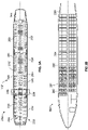
- FIG 3A illustrates a top plan view of an internal cabin 230 of an aircraft, according to an example of the present disclosure.
- the internal cabin 230 may be within the fuselage 232 of the aircraft, such as the fuselage 218 of Figure 2 .
- one or more fuselage walls may define the internal cabin 230.
- the internal cabin 230 includes multiple areas, including a front section 233, a first-class section 234, a business class section 236, a front galley station 238, an expanded economy or coach section 240, a standard economy of coach section 242, and an aft section 244, which may include multiple lavatories and galley stations.
- the internal cabin 230 may include more or less areas than shown.
- the internal cabin 230 may not include a first-class section, and may include more or less galley stations than shown.
- Each of the sections may be separated by a cabin transition area 246, which may include class divider assemblies between aisles.
- the internal cabin 230 includes two aisles 250 and 252 that lead to the aft section 244.
- the internal cabin 230 may have less or more aisles than shown.
- the internal cabin 230 may include a single aisle that extends through the center of the internal cabin 230 that leads to the aft section 244.
- the disinfecting system 100 shown in Figure 1 may be used to disinfect or otherwise sanitize various disinfection zones within the internal cabin 230, such as air space therein, passenger seats 290, monuments, stowage bin assemblies, components on and within lavatories, galley equipment and components, and/or the like.
- Figure 3B illustrates a top plan view of an internal cabin 280 of an aircraft, according to an example of the present disclosure.
- the internal cabin 280 is an example of the internal cabin 230 shown in Figure 2 .
- the internal cabin 280 may be within a fuselage 281 of the aircraft.
- one or more fuselage walls may define the internal cabin 280.
- the internal cabin 280 includes multiple areas, including a main cabin 282 having passenger seats, and an aft section 285 behind the main cabin 282. It is to be understood that the internal cabin 280 may include more or less areas than shown.
- the internal cabin 280 may include a single aisle 284 that leads to the aft section 285.
- the single aisle 284 may extend through the center of the internal cabin 280 that leads to the aft section 285.
- the single aisle 284 may be coaxially aligned with a central longitudinal plane of the internal cabin 280.
- the disinfecting system 100 shown in Figure 1 may be used to disinfect or otherwise sanitize various disinfection zones within the internal cabin 280, such as air space therein, passenger seats 290, monuments, stowage bin assemblies, components on and within lavatories, galley equipment and components, and/or the like.
- Figure 4 illustrates a perspective interior view of an internal cabin 300 of an aircraft, according to an example of the present disclosure.
- the internal cabin 300 includes outboard walls 302 connected to a ceiling 304.
- Windows 306 may be formed within the outboard walls 302.
- a floor 308 supports rows of seats 310.
- a row 312 may include two seats 310 on either side of an aisle 313. However, the row 312 may include more or less seats 310 than shown. Additionally, the internal cabin 300 may include more aisles than shown.
- PSUs Passenger service units
- the PSUs 314 are secured between an outboard wall 302 and the ceiling 304 on either side of the aisle 313.
- the PSUs 314 extend between a front end and rear end of the internal cabin 300.
- a PSU 314 may be positioned over each seat 310 within a row 312.
- Each PSU 314 may include a housing 316 that generally contains vents, reading lights, an oxygen bag drop panel, an attendant request button, and other such controls over each seat 310 (or groups of seats) within a row 312.
- Overhead stowage bin assemblies 318 are secured to the ceiling 304 and/or the outboard wall 302 above and inboard from the PSU 314 on either side of the aisle 313.
- the overhead stowage bin assemblies 318 are secured over the seats 310.
- the overhead stowage bin assemblies 318 extend between the front and rear end of the internal cabin 300.
- Each stowage bin assembly 318 may include a pivot bin or bucket 320 pivotally secured to a strongback.
- the overhead stowage bin assemblies 318 may be positioned above and inboard from lower surfaces of the PSUs 314.
- the overhead stowage bin assemblies 318 are configured to be pivoted open in order to receive passenger carry-on baggage and personal items, for example.
- outboard means a position that is further away from a central longitudinal plane 322 of the internal cabin 300 as compared to another component.
- inboard means a position that is closer to the central longitudinal plane 3622 of the internal cabin 300 as compared to another component.
- a lower surface of a PSU 314 may be outboard in relation to a stowage bin assembly 318.
- the disinfecting system 100 shown in Figure 1 may be used to disinfect or otherwise sanitize various disinfection zones within the internal cabin 300, such as air space therein, passenger seats 310, monuments, stowage bin assemblies, components on and within lavatories, galley equipment and components, and/or the like.
- the seats 310, the PSUs 314, spacer panels between the PSUs 314, the stowage bin assemblies 318, the outboard walls 302, the ceiling 304, and the like are examples of structures, such as the structure 108 shown in Figure 1 , to which the disinfecting system 100 can be moveably secured.
- Figure 5 illustrates a lateral view of the disinfecting system 100 within an internal cabin 400 of a vehicle 402 (such as a commercial aircraft), according to an example of the present disclosure.
- the internal cabin 400 is an example of the enclosed space 102 shown in Figure 1 .
- the disinfecting system 100 is moveably coupled to a spacer panel 404 above a seat 406 within the internal cabin 400.
- the spacer panel 404 is an example of the structure 108 shown in Figure 1 .
- the disinfecting system 100 includes a plurality of arm segments that are configured to move relative to one another.
- the plurality of arm segments can be moveably coupled to each other through a plurality of pivot joints. Any of the examples described herein can include the plurality of arm segments.
- the disinfecting system 100 includes the articulating arm 104, which includes a first arm segment 410 and a second arm segment 412.
- the first arm segment 410 moveably coupled to the spacer panel 404 through a first pivot joint 110a.
- the first arm segment 410 is coupled to the second arm segment 412 through a second pivot joint 110b.
- the articulating arm 104 is able to pivot, rotate, and/or otherwise move about the first pivot joint 110a and the second pivot joint 110b.
- the first pivot joint 110a and the second pivot joint 110b allow the articulating arm 104 to move between the deployed position, as shown in Figure 5 , and a stowed position, in which the articulating arm 104 recedes into a cavity 420 formed in the spacer panel 404.
- the UV lamp 106 may also be configured to slide or otherwise move relative to the second arm segment 412 in the direction of arrows A, such as via one or more tracks.
- the UV lamp 106 may be fixed in relation to the second arm segment 412.
- the articulating arm 104 allows the disinfecting system 100 to be moved to the deployed position, where the UV lamp 106 is closer to the disinfection zone 114, such as a breathing space of an individual 424 seated within the seat 406. As shown in Figure 5 , the pivot joints 110a and 110b allow the articulating arm 104 to articulate relative to the X-Z plane.
- Figure 6 illustrates a front view of the disinfecting system 100 within the internal cabin of Figure 5 .
- the spacer panel 404 is adjacent a PSU 405.
- the pivot joints 110a and 110b allow the articulating arm 104 to articulate relative to the Y-Z plane, as well as the X-Y plane, in addition to the X-Z plane.
- the articulating arm 104 may include more or less pivot joints than those shown.
- the articulating arm 104 may include a single arm segment coupled to the spacer panel 404 through a single pivot joint.
- the articulating 104 may include three arm segments coupled to one another through at least three pivot joints.
- the activation member 124 can be coupled to a portion of the seat 406 (such as an armrest), a portion of a PSU, and/or the like.
- the system may not include the activation member 124.
- Figure 7 illustrates a lateral view of a disinfecting system 100 within an internal cabin 500 of a vehicle 502, according to an example of the present disclosure.
- Figure 8 illustrates a front view of the disinfecting system 100 within the internal cabin 500 of Figure 7 .
- the structure to which the disinfecting system 100 is moveably secured is a headrest 510 of a seat assembly 512.
- the articulating arm 104 includes a first arm segment 511 coupled to a second arm segment 513 through a first pivot joint 110a, which allows the first arm segment 511 and the second arm segment 513 to articulate relative to one another.
- the second arm segment 513 can moveably coupled to the headrest 510 through a second pivot joint, and/or a telescoping connection. In this manner, the articulating arm 104 can be moved between the deployed position, as shown in Figure 7 , and a stowed position, in which the disinfecting system 100 is stowed behind the headrest 510.
- the disinfecting system 100 also includes a distance ranging unit 530, such a laser sensor, an infrared red sensor, an ultrasonic sensor, or the like.
- the distance ranging unit 530 is configured to detect an appropriate distance for the disinfecting system 100 relative to the individual 540.
- the distance ranging unit 530 can be in communication with the UV lamp 106, such as through one or more wired or wireless connections.
- the UV lamp 106 is configured to emit UV light in response to receiving a signal from the distance ranging unit 530 indicating that the UV lamp 106 is at a predetermined distance from the individual 540 associated with a predetermined appropriate distance.
- the distance ranging unit 530 can be used with any of the examples described herein.
- the disinfecting system 100 may not include the distance ranging unit 530.
- the disinfecting system 100 can be moveably secured to other portions of the seat assembly 512, such as to a lateral portion of the headrest 512, an armrest 514, or the like. Further, the articulating arm 104 may include more or less arm segments than shown.
- the activation member 124 can be coupled to a portion of the seat assembly 512 (such as an armrest), a portion of a PSU, and/or the like.
- the system may not include the activation member 124.
- Figure 9 illustrates a lateral view of a disinfecting system 100 within an internal cabin 600 of a vehicle 602, according to an example of the present disclosure.
- Figure 10 illustrates a front view of the disinfecting system 100 within the internal cabin 600 of Figure 9 .
- the disinfecting system 100 is moveably coupled to a PSU 604 or a spacer panel connected thereto.
- the articulating arm 104 may include more or less arm segments than shown.
- the activation member 124 can be coupled to a portion of the seat (such as an armrest), a portion of a PSU, and/or the like.
- the system may not include the activation member 124.
- FIG 11 illustrates a front view of a disinfecting system 100 within an internal cabin 700 of a vehicle 702, according to an example of the present disclosure.
- the disinfecting system 100 includes a support bar 704, which may be coupled to a structure, such as a PSU 706, a spacer panel connected thereto, and/or the like.
- the support bar 704 can be fixed to the structure, or moveable coupled thereto, such as through one or more pivot joints.
- a plurality of articulating arms 104a, 104b, and 104c such as any of those described herein are moveably coupled to the support bar 704, such as via one or more pivot joints.
- Each articulating arm 104a, 104b, and 104c is in turn coupled to a UV lamp 106a, 116b, and 116c, respectively.
- the support bar 704 and the articulating arms 104a-c can be moved to position the UV lamps 116a-116c over respective seats 706a, 706b, and 706c. More or less articulating arms and UV lamps can be coupled to the support bar 704.
- the activation member 124 can be coupled to a portion of the seat (such as an armrest), a portion of a PSU, and/or the like.
- the system may not include the activation member 124.
- FIG 12 illustrates a lateral view of a disinfecting system 100 secured to a headrest 800 of a seat 802, according to an example of the present disclosure.
- Figure 13 illustrates a front perspective view of the disinfecting system 100 of Figure 12 .
- the disinfecting system 100 includes the articulating arm 104 pivotally coupled to a side 806 of the headrest 800 via a pivot joint 110, which allows the articulating arm 104 to pivot between the deployed position shown in Figures 12 and 13 in which a main body 810 of the disinfecting system 100 is disposed to a side of a head 812 of an individual 814 seated within the seat 802, and a stowed position, in which the main body 810 is disposed between seats, behind and to a side of the seat, and/or the like.
- the main body 810 includes the UV lamp 106, which is configured to emit the UV light into the disinfection zone 114, such as the breathing space of the individual 814.
- the UV lamp 106 may be embedded within the main body 810 and configured to emit the UV light into an air stream passing through the main body 810, and which is expelled into the disinfection zone 114. In this manner, the UV lamp 106 does not directly emit the UV light into the disinfection zone 114, but rather within an air channel within the main body 810.
- An internal fan 830 may be within the main body 810, and is configured to blow the disinfected air stream out through air outlets 832 formed in the main body 810.
- the disinfecting system 100 includes a first UV lamp 106a that is configured to emit the UV light into the disinfection zone 114, as well as an embedded second UV lamp 106b within the main body 810, which is configured to emit the UV light into an air stream within the main body 810.
- the disinfecting system 100 include one of the UV lamp 106a or the UV lamp 106b.
- the activation member 124 can be coupled to a portion of the seat (such as an armrest), a portion of a PSU, and/or the like.
- the system may not include the activation member 124.
- FIG 14 illustrates a flow chart of a disinfecting method, according to an example of the present disclosure.
- the disinfecting method is for the enclosed space 102, and includes moveably coupling, at 900, the articulating arm 104 to the structure 108 within the enclosed space 102; coupling, at 902, the UV lamp 106 to the articulating arm 104, wherein the UV lamp 106 is configured to emit the UV light 120 toward the disinfection zone 114 within the enclosed space 102; and moving, at 904, the UV lamp 106 via the articulating arm 104 relative to the disinfection zone 114.
- said moving 904 includes moving the UV lamp 106 between a stowed position and a deployed position.
- the enclosed space 102 is an internal cabin of a vehicle.
- the structure 108 is one or more of a spacer panel, a passenger service unit (PSU), a portion of a seat, or an overhead stowage bin assembly within the internal cabin.
- PSU passenger service unit
- examples of the present disclosure provide UV light disinfecting systems and methods that can be quickly and easily positioned with respect to an area, space or the like that is to be disinfected. Further, examples of the present disclosure provide UV light disinfecting systems and methods that can be moveably secured within a confined space, such as within an internal cabin of a vehicle. Also, examples of the present disclosure provide UV light disinfecting systems and methods that utilize a reduced amount of power, as the UV lamps can be moved into a close proximity with respect to a disinfection zone.
- a structure, limitation, or element that is "configured to” perform a task or operation is particularly structurally formed, constructed, or adapted in a manner corresponding to the task or operation.
- an object that is merely capable of being modified to perform the task or operation is not “configured to” perform the task or operation as used herein.
Abstract
Description
- Examples of the present disclosure generally relate to systems and methods for sanitizing surfaces within an enclosed space, such an internal cabin of a commercial aircraft, and more particularly to systems and methods for moveably supporting an ultraviolet (UV) light lamp within the enclosed space.
- Vehicles such as commercial aircraft are used to transport passengers between various locations. Systems are currently being developed to disinfect or otherwise sanitize surfaces within aircraft, for example, that use ultraviolet (UV) light.
- Typically, UV light disinfection is more effective when a UV light emitter is closer to a surface that is to be disinfected. However, in various settings, such as within the confined space of an internal cabin of a commercial aircraft, placing UV light emitters close to surfaces or areas to be disinfected may not be practical. As such, a UV light emitter may be spaced apart from an area or space that is to be disinfected at a relatively long distance. In such a scenario, the UV light emitter typically needs to be of sufficient power to effectively disinfect the target area or space. With increased distance to the target, the power typically needed for the UV light emitter is also generally increased. As can be appreciated, effective UV light disinfection within a particular setting may typically require an increased amount of time and power.
- A need exists for a UV light disinfecting system and method that can be quickly and easily positioned with respect to an area, space or the like that is to be disinfected. Further, a need exists for a UV light disinfecting system and method that can be moveably secured within a confined space, such as within an internal cabin of a vehicle. Also, a need exists for a UV light disinfecting system and method that utilize less power.
- With those needs in mind, certain examples of the present disclosure provide a disinfecting system for an enclosed space. The disinfecting system includes an articulating arm moveably coupled to a structure within the enclosed space. An ultraviolet (UV) lamp is coupled to the articulating arm. The UV lamp is configured to emit UV light toward a disinfection zone within the enclosed space. The articulating arm allows the UV lamp to move relative to the disinfection zone.
- In at least one example, the articulating arm includes one or more pivot joints. As a further example, one or more dampers are coupled to the one or more pivot joints.
- In at least one example, the articulating arm allows the UV lamp to move between a stowed position and a deployed position.
- In at least one example, a latch is coupled to the structure and the articulating arm. The latch is selectively moveable between a locked position and an unlocked position. As a further example, an activation member is configured to control the latch.
- In at least one example, the enclosed space is an internal cabin of a vehicle. In at least one example, the structure is a spacer panel within the internal cabin. In at least one example, the spacer panel includes a cavity. At least a portion of the articulating is within the cavity in a stowed position.
- In at least one example, the structure is a passenger service unit (PSU) within the internal cabin.
- In at least one example, the structure is a portion of a seat within the internal cabin. For example, the portion of the seat is a headrest. As a further example, the UV lamp is configured to emit the UV light into the disinfection zone including a breathing space of an individual seated within the seat. As another example, the UV lamp is embedded within a main body, and the UV lamp is configured to emit the UV light into an air stream within the main body.
- In at least one example, the articulating arm includes a plurality of arm segments that are configured to move relative to one another. Further, in at least one example, a plurality of pivot joints are between the plurality of arm segments.
- In at least one example, the UV lamp is moveable in relation to the articulating arm.
- In at least one example, the disinfecting system also includes a distance ranging unit.
- In an example, the disinfecting system also includes a support bar. The articulating arm is moveably coupled to the support bar. Further, the support bar can be moveably coupled to the structure. As a further example, at least one additional articulating arm is moveably coupled to the support bar, and at least one additional UV lamp is coupled to the at least one additional articulating arm.
- Certain examples of the present disclosure provide a disinfecting method for an enclosed space. The disinfecting method includes moveably coupling an articulating arm to a structure within the enclosed space; coupling an ultraviolet (UV) lamp to the articulating arm, wherein the UV lamp is configured to emit UV light toward a disinfection zone within the enclosed space; and moving the UV lamp via the articulating arm relative to the disinfection zone.
- Certain examples of the present disclosure provide an enclosed space including a structure, and a disinfecting system moveably coupled to the structure, as described herein.
-
-
Figure 1 illustrates a schematic block diagram of a disinfecting system within an enclosed space, according to an example of the present disclosure. -
Figure 2 illustrates a perspective front view of an aircraft, according to an example of the present disclosure. -
Figure 3A illustrates a top plan view of an internal cabin of an aircraft, according to an example of the present disclosure. -
Figure 3B illustrates a top plan view of an internal cabin of an aircraft, according to an example of the present disclosure. -
Figure 4 illustrates a perspective interior view of an internal cabin of an aircraft, according to an example of the present disclosure. -
Figure 5 illustrates a lateral view of a disinfecting system within an internal cabin of a vehicle, according to an example of the present disclosure. -
Figure 6 illustrates a front view of the disinfecting system within the internal cabin ofFigure 5 . -
Figure 7 illustrates a lateral view of a disinfecting system within an internal cabin of a vehicle, according to an example of the present disclosure. -
Figure 8 illustrates a front view of the disinfecting system within the internal cabin ofFigure 7 . -
Figure 9 illustrates a lateral view of a disinfecting system within an internal cabin of a vehicle, according to an example of the present disclosure. -
Figure 10 illustrates a front view of the disinfecting system within the internal cabin ofFigure 9 . -
Figure 11 illustrates a front view of a disinfecting system within an internal cabin of a vehicle, according to an example of the present disclosure. -
Figure 12 illustrates a lateral view of a disinfecting system secured to a headrest, according to an example of the present disclosure. -
Figure 13 illustrates a front perspective view of the disinfecting system ofFigure 12 . -
Figure 14 illustrates a flow chart of a disinfecting method, according to an example of the present disclosure. - The foregoing summary, as well as the following detailed description of certain examples will be better understood when read in conjunction with the appended drawings. As used herein, an element or step recited in the singular and preceded by the word "a" or "an" should be understood as not necessarily excluding the plural of the elements or steps. Further, references to "one example" are not intended to be interpreted as excluding the existence of additional examples that also incorporate the recited features. Moreover, unless explicitly stated to the contrary, examples "comprising" or "having" an element or a plurality of elements having a particular condition can include additional elements not having that condition.
- Certain examples of the present disclosure a system and a method for positioning an ultraviolet (UV) lamp in close proximity to a target disinfection zone. The system and method include a mechanism that moves the UV lamp in relation to a structure, such as between a stowed position and a deployed position. In at least one example, the mechanism includes an articulating arm that moveably couples the UV lamp to a structure within an enclosed space, such as an internal cabin of a vehicle.
-
Figure 1 illustrates a schematic block diagram of adisinfecting system 100 within anenclosed space 102, according to an example of the present disclosure. In at least one example, theenclosed space 102 is an internal cabin of a vehicle, such as a commercial aircraft. In at least one other example, theenclosed space 102 is one or more rooms within a residential or commercial building. As an example, theenclosed space 102 can be an operating room within a hospital. In at least one other example, theenclosed space 102 is an open air venue, such as a stadium, concert space, and/or the like. - The disinfecting
system 100 includes an articulatingarm 104 that moveably secures an ultraviolet (UV)lamp 106 to astructure 108 within theenclosed space 102. In at least one example, thestructure 108 is a ceiling within theenclosed space 102. As another example, thestructure 108 is a panel within the enclosed space. For example, thestructure 108 is a wall. In at least one example, thestructure 108 is a spacer panel, a passenger service unit (PSU), overhead stowage bin assembly, or the like within an internal cabin of a vehicle. In at least one example, thestructure 108 is a seat assembly within the enclosed space. For example, thestructure 108 is a seat assembly within an internal cabin of a vehicle. - The articulating
arm 104 includes one ormore pivot joints 110 that allow the articulatingarm 104 to pivot, rotate, or otherwise move. In at least one example, one ormore dampers 112 are coupled to the one ormore pivot joints 110 to control a rate of motion of the articulatingarm 104. For example, thedampers 112 include or more brakes, clutches, servos, and/or the like. As an example, thedampers 112 can include a pneumatic damper. As another example, thedampers 112 can include a metal brake (such as an aluminum brake) coupled to a passive magnet. As another example, thedampers 112 can include electromagnetic brakes and/or clutches. Alternatively, the articulatingarm 104 may not include any damper. - The articulating
arm 104 allows theUV lamp 106 to be moved between various positions. For example, the articulatingarm 104 is configured to allow theUV lamp 106 to be moved between a stowed position (such as recessed within a ceiling, spacer panel, PSU, headrest of a seat assembly, or the like), and a deployed position, in which adisinfection zone 114 is disinfected through operation of theUV lamp 106. The damper(s) 112 control a rate of motion of the articulatingarm 104 as theUV lamp 106 is moved between different positions. - Optionally, the
arm 104 can be configured to move through ways other than articulation. For example, thearm 104 can be pivotal, rotational, telescoping, and/or the like. As another example, thearm 104 can be fixed in position and not configured to move. - The
UV lamp 106 includes ahousing 116 having one or more UVlight emitters 118, such as one or more bulbs, light emitting diodes (LEDs), and/or the like. The UVlight emitters 118 are configured to emitUV light 120 onto or into thedisinfection zone 114. In at least one example, thedisinfection zone 114 includes an air space, such as a breathing space within theenclosed space 102. As another example, thedisinfection zone 114 includes a surface of a structure (for example, thestructure 108 and/or another structure) that is to be disinfected. The surface can be any physical surface within theenclosed space 102. For example, the surface can include walls, floors, ceilings, tables, countertops, seats, and/or the like within theenclosed space 102. In the example in which theenclosed space 102 is an internal cabin of a vehicle, the surfaces includes floors, walls, ceilings, passenger seats, counters, drawers, cabinets, and/or the like, such as within a passenger cabin, galleys, lavatories, and/or the like. As another example, thedisinfection zone 114 includes an air space and a surface of a structure. - In at least one example, the
UV lamp 106 emits the UV light 120 (such as through the UV light emitters 118) in a far UV light spectrum, such as at a wavelength of 222 nm, which neutralizes (such as kills) microbes (for example, viruses and bacteria), while posing no risk to humans. TheUV lamp 106 may be used within theenclosed space 102 to decontaminate and kill pathogens. Optionally, theUV lamp 106 can be configured to emit theUV light 120 at other wavelengths, such as the UVC spectrum (for example, at a wavelength of 254 nm). - In at least one example, a
latch 122 is coupled to thestructure 108. Thelatch 122 also couples to the articulatingarm 104. Thelatch 122 is configured to be selectively engaged or otherwise moved between a locked position and an unlocked position, so that the articulatingarm 104 can be locked in position (such as in the stowed position), and unlocked (such as in the deployed position). For example, in the locked position, thelatch 122 ensures that the articulatingarm 104 is in the stowed position. In the unlocked position, the latch uncouples from the articulatingarm 104, and the articulatingarm 104 and theUV lamp 106 can moved into (for example, fall) into the deployed position, with the movement being controlled by the one ormore dampers 112. - In at least one example, an
activation member 124 that is configured to control thelatch 122. For example, theactivation member 124 is coupled to aswitch 126, which is in turn coupled to thelatch 122. For example, theactivation member 124 is a button, dial, lever, or the like that is configured to be engaged by an individual. Theactivation member 124 can be disposed on or within thestructure 108. For example, theactivation member 124 can be in an armrest of a seat assembly, or secured to a wall, ceiling, or the like. As theactivation member 124 is engaged by an individual, theswitch 126 moves from the locked position to the unlocked position, thereby allowing thedisinfecting system 100 to move into the deployed position. An individual may move thedisinfecting system 100 back to the stowed position, at which thelatch 122 automatically locks thedisinfecting system 100 in place. Optionally, the disinfectingsystem 100 may not be coupled to thestructure 108 through thelatch 122. Also, optionally, the system may not include theactivation member 124 and theswitch 126. - As described herein, the disinfecting
system 100 for theenclosed space 102 includes the articulatingarm 104 moveably coupled to thestructure 108 within theenclosed space 102. TheUV lamp 106 is coupled to the articulatingarm 104. TheUV lamp 106 is configured to emit theUV light 120 toward (and subsequently onto and/or into) thedisinfection zone 114 within theenclosed space 102. The articulatingarm 104 allows theUV lamp 106 to move relative to thedisinfection zone 114. -
Figure 2 illustrates a perspective front view of anaircraft 210, according to an example of the present disclosure. Theaircraft 210 includes apropulsion system 212 that includesengines 214, for example. Optionally, thepropulsion system 212 may includemore engines 214 than shown. Theengines 214 are carried bywings 216 of theaircraft 210. In other examples, theengines 214 may be carried by afuselage 218 and/or anempennage 220. Theempennage 220 may also supporthorizontal stabilizers 222 and avertical stabilizer 224. - The
fuselage 218 of theaircraft 210 defines aninternal cabin 230, which includes a flight deck or cockpit, one or more work sections (for example, galleys, personnel carry-on baggage areas, and the like), one or more passenger sections (for example, first class, business class, and coach sections), one or more lavatories, and/or the like. Theinternal cabin 230 is an example of anenclosed space 102, as shown inFigure 1 . - Alternatively, instead of an aircraft, examples of the present disclosure may be used with various other vehicles, such as automobiles, buses, locomotives and train cars, watercraft, and the like. Further, examples of the present disclosure may be used with respect to fixed structures, such as commercial and residential buildings. In general, the sanitizing systems described herein may be used to sanitize various components, such as within enclosed spaces, outdoor spaces, and the like.
-
Figure 3A illustrates a top plan view of aninternal cabin 230 of an aircraft, according to an example of the present disclosure. Theinternal cabin 230 may be within thefuselage 232 of the aircraft, such as thefuselage 218 ofFigure 2 . For example, one or more fuselage walls may define theinternal cabin 230. Theinternal cabin 230 includes multiple areas, including afront section 233, a first-class section 234, abusiness class section 236, afront galley station 238, an expanded economy orcoach section 240, a standard economy ofcoach section 242, and anaft section 244, which may include multiple lavatories and galley stations. It is to be understood that theinternal cabin 230 may include more or less areas than shown. For example, theinternal cabin 230 may not include a first-class section, and may include more or less galley stations than shown. Each of the sections may be separated by acabin transition area 246, which may include class divider assemblies between aisles. - As shown in
Figure 3A , theinternal cabin 230 includes twoaisles aft section 244. Optionally, theinternal cabin 230 may have less or more aisles than shown. For example, theinternal cabin 230 may include a single aisle that extends through the center of theinternal cabin 230 that leads to theaft section 244. - The disinfecting
system 100 shown inFigure 1 may be used to disinfect or otherwise sanitize various disinfection zones within theinternal cabin 230, such as air space therein,passenger seats 290, monuments, stowage bin assemblies, components on and within lavatories, galley equipment and components, and/or the like. -
Figure 3B illustrates a top plan view of aninternal cabin 280 of an aircraft, according to an example of the present disclosure. Theinternal cabin 280 is an example of theinternal cabin 230 shown inFigure 2 . Theinternal cabin 280 may be within afuselage 281 of the aircraft. For example, one or more fuselage walls may define theinternal cabin 280. Theinternal cabin 280 includes multiple areas, including amain cabin 282 having passenger seats, and anaft section 285 behind themain cabin 282. It is to be understood that theinternal cabin 280 may include more or less areas than shown. - The
internal cabin 280 may include asingle aisle 284 that leads to theaft section 285. Thesingle aisle 284 may extend through the center of theinternal cabin 280 that leads to theaft section 285. For example, thesingle aisle 284 may be coaxially aligned with a central longitudinal plane of theinternal cabin 280. - The disinfecting
system 100 shown inFigure 1 may be used to disinfect or otherwise sanitize various disinfection zones within theinternal cabin 280, such as air space therein,passenger seats 290, monuments, stowage bin assemblies, components on and within lavatories, galley equipment and components, and/or the like. -
Figure 4 illustrates a perspective interior view of aninternal cabin 300 of an aircraft, according to an example of the present disclosure. Theinternal cabin 300 includesoutboard walls 302 connected to aceiling 304.Windows 306 may be formed within theoutboard walls 302. Afloor 308 supports rows ofseats 310. As shown inFigure 4 , arow 312 may include twoseats 310 on either side of anaisle 313. However, therow 312 may include more orless seats 310 than shown. Additionally, theinternal cabin 300 may include more aisles than shown. - Passenger service units (PSUs) 314 are secured between an
outboard wall 302 and theceiling 304 on either side of theaisle 313. ThePSUs 314 extend between a front end and rear end of theinternal cabin 300. For example, aPSU 314 may be positioned over eachseat 310 within arow 312. EachPSU 314 may include ahousing 316 that generally contains vents, reading lights, an oxygen bag drop panel, an attendant request button, and other such controls over each seat 310 (or groups of seats) within arow 312. - Overhead
stowage bin assemblies 318 are secured to theceiling 304 and/or theoutboard wall 302 above and inboard from thePSU 314 on either side of theaisle 313. The overheadstowage bin assemblies 318 are secured over theseats 310. The overheadstowage bin assemblies 318 extend between the front and rear end of theinternal cabin 300. Eachstowage bin assembly 318 may include a pivot bin orbucket 320 pivotally secured to a strongback. The overheadstowage bin assemblies 318 may be positioned above and inboard from lower surfaces of thePSUs 314. The overheadstowage bin assemblies 318 are configured to be pivoted open in order to receive passenger carry-on baggage and personal items, for example. - As used herein, the term "outboard" means a position that is further away from a central
longitudinal plane 322 of theinternal cabin 300 as compared to another component. The term "inboard" means a position that is closer to the central longitudinal plane 3622 of theinternal cabin 300 as compared to another component. For example, a lower surface of aPSU 314 may be outboard in relation to astowage bin assembly 318. - The disinfecting
system 100 shown inFigure 1 may be used to disinfect or otherwise sanitize various disinfection zones within theinternal cabin 300, such as air space therein,passenger seats 310, monuments, stowage bin assemblies, components on and within lavatories, galley equipment and components, and/or the like. Theseats 310, thePSUs 314, spacer panels between thePSUs 314, thestowage bin assemblies 318, theoutboard walls 302, theceiling 304, and the like are examples of structures, such as thestructure 108 shown inFigure 1 , to which thedisinfecting system 100 can be moveably secured. -
Figure 5 illustrates a lateral view of thedisinfecting system 100 within aninternal cabin 400 of a vehicle 402 (such as a commercial aircraft), according to an example of the present disclosure. Theinternal cabin 400 is an example of theenclosed space 102 shown inFigure 1 . The disinfectingsystem 100 is moveably coupled to aspacer panel 404 above aseat 406 within theinternal cabin 400. Thespacer panel 404 is an example of thestructure 108 shown inFigure 1 . - In at least one example, the disinfecting
system 100 includes a plurality of arm segments that are configured to move relative to one another. The plurality of arm segments can be moveably coupled to each other through a plurality of pivot joints. Any of the examples described herein can include the plurality of arm segments. For example, the disinfectingsystem 100 includes the articulatingarm 104, which includes afirst arm segment 410 and asecond arm segment 412. Thefirst arm segment 410 moveably coupled to thespacer panel 404 through a first pivot joint 110a. Thefirst arm segment 410 is coupled to thesecond arm segment 412 through a second pivot joint 110b. The articulatingarm 104 is able to pivot, rotate, and/or otherwise move about the first pivot joint 110a and the second pivot joint 110b. The first pivot joint 110a and the second pivot joint 110b allow the articulatingarm 104 to move between the deployed position, as shown inFigure 5 , and a stowed position, in which the articulatingarm 104 recedes into acavity 420 formed in thespacer panel 404. TheUV lamp 106 may also be configured to slide or otherwise move relative to thesecond arm segment 412 in the direction of arrows A, such as via one or more tracks. Optionally, theUV lamp 106 may be fixed in relation to thesecond arm segment 412. - The articulating
arm 104 allows thedisinfecting system 100 to be moved to the deployed position, where theUV lamp 106 is closer to thedisinfection zone 114, such as a breathing space of an individual 424 seated within theseat 406. As shown inFigure 5 , thepivot joints arm 104 to articulate relative to the X-Z plane. -
Figure 6 illustrates a front view of thedisinfecting system 100 within the internal cabin ofFigure 5 . Thespacer panel 404 is adjacent aPSU 405. Referring toFigures 5 and6 , thepivot joints arm 104 to articulate relative to the Y-Z plane, as well as the X-Y plane, in addition to the X-Z plane. - The articulating
arm 104 may include more or less pivot joints than those shown. For example, the articulatingarm 104 may include a single arm segment coupled to thespacer panel 404 through a single pivot joint. As another example, the articulating 104 may include three arm segments coupled to one another through at least three pivot joints. - Referring to
Figures 1 ,5 , and6 , theactivation member 124 can be coupled to a portion of the seat 406 (such as an armrest), a portion of a PSU, and/or the like. Optionally, the system may not include theactivation member 124. -
Figure 7 illustrates a lateral view of adisinfecting system 100 within aninternal cabin 500 of avehicle 502, according to an example of the present disclosure.Figure 8 illustrates a front view of thedisinfecting system 100 within theinternal cabin 500 ofFigure 7 . Referring toFigures 7 and8 , in this example, the structure to which thedisinfecting system 100 is moveably secured is aheadrest 510 of aseat assembly 512. The articulatingarm 104 includes afirst arm segment 511 coupled to asecond arm segment 513 through a first pivot joint 110a, which allows thefirst arm segment 511 and thesecond arm segment 513 to articulate relative to one another. Thesecond arm segment 513 can moveably coupled to theheadrest 510 through a second pivot joint, and/or a telescoping connection. In this manner, the articulatingarm 104 can be moved between the deployed position, as shown inFigure 7 , and a stowed position, in which thedisinfecting system 100 is stowed behind theheadrest 510. - In at least one example, the disinfecting
system 100 also includes adistance ranging unit 530, such a laser sensor, an infrared red sensor, an ultrasonic sensor, or the like. Thedistance ranging unit 530 is configured to detect an appropriate distance for thedisinfecting system 100 relative to the individual 540. Thedistance ranging unit 530 can be in communication with theUV lamp 106, such as through one or more wired or wireless connections. In at least one example, theUV lamp 106 is configured to emit UV light in response to receiving a signal from thedistance ranging unit 530 indicating that theUV lamp 106 is at a predetermined distance from the individual 540 associated with a predetermined appropriate distance. Thedistance ranging unit 530 can be used with any of the examples described herein. Optionally, the disinfectingsystem 100 may not include thedistance ranging unit 530. - The disinfecting
system 100 can be moveably secured to other portions of theseat assembly 512, such as to a lateral portion of theheadrest 512, anarmrest 514, or the like. Further, the articulatingarm 104 may include more or less arm segments than shown. - Referring to
Figures 1 ,7 , and8 , theactivation member 124 can be coupled to a portion of the seat assembly 512 (such as an armrest), a portion of a PSU, and/or the like. Optionally, the system may not include theactivation member 124. -
Figure 9 illustrates a lateral view of adisinfecting system 100 within aninternal cabin 600 of avehicle 602, according to an example of the present disclosure.Figure 10 illustrates a front view of thedisinfecting system 100 within theinternal cabin 600 ofFigure 9 . Referring toFigures 9 and10 , the disinfectingsystem 100 is moveably coupled to aPSU 604 or a spacer panel connected thereto. The articulatingarm 104 may include more or less arm segments than shown. - Referring to
Figures 1 ,9 , and10 , theactivation member 124 can be coupled to a portion of the seat (such as an armrest), a portion of a PSU, and/or the like. Optionally, the system may not include theactivation member 124. -
Figure 11 illustrates a front view of adisinfecting system 100 within aninternal cabin 700 of avehicle 702, according to an example of the present disclosure. In this example, the disinfectingsystem 100 includes asupport bar 704, which may be coupled to a structure, such as aPSU 706, a spacer panel connected thereto, and/or the like. Thesupport bar 704 can be fixed to the structure, or moveable coupled thereto, such as through one or more pivot joints. A plurality of articulatingarms support bar 704, such as via one or more pivot joints. Each articulatingarm UV lamp support bar 704 and the articulatingarms 104a-c can be moved to position theUV lamps 116a-116c overrespective seats support bar 704. - Referring to
Figures 1 and11 , theactivation member 124 can be coupled to a portion of the seat (such as an armrest), a portion of a PSU, and/or the like. Optionally, the system may not include theactivation member 124. -
Figure 12 illustrates a lateral view of adisinfecting system 100 secured to aheadrest 800 of aseat 802, according to an example of the present disclosure.Figure 13 illustrates a front perspective view of thedisinfecting system 100 ofFigure 12 . The disinfectingsystem 100 includes the articulatingarm 104 pivotally coupled to aside 806 of theheadrest 800 via a pivot joint 110, which allows the articulatingarm 104 to pivot between the deployed position shown inFigures 12 and 13 in which amain body 810 of thedisinfecting system 100 is disposed to a side of ahead 812 of an individual 814 seated within theseat 802, and a stowed position, in which themain body 810 is disposed between seats, behind and to a side of the seat, and/or the like. - In at least one example, the
main body 810 includes theUV lamp 106, which is configured to emit the UV light into thedisinfection zone 114, such as the breathing space of the individual 814. Optionally, theUV lamp 106 may be embedded within themain body 810 and configured to emit the UV light into an air stream passing through themain body 810, and which is expelled into thedisinfection zone 114. In this manner, theUV lamp 106 does not directly emit the UV light into thedisinfection zone 114, but rather within an air channel within themain body 810. Aninternal fan 830 may be within themain body 810, and is configured to blow the disinfected air stream out throughair outlets 832 formed in themain body 810. In at least one example, the disinfectingsystem 100 includes a first UV lamp 106a that is configured to emit the UV light into thedisinfection zone 114, as well as an embedded second UV lamp 106b within themain body 810, which is configured to emit the UV light into an air stream within themain body 810. In at least one example, the disinfectingsystem 100 include one of the UV lamp 106a or the UV lamp 106b. - Referring to
Figures 1 ,12, and 13 , theactivation member 124 can be coupled to a portion of the seat (such as an armrest), a portion of a PSU, and/or the like. Optionally, the system may not include theactivation member 124. -
Figure 14 illustrates a flow chart of a disinfecting method, according to an example of the present disclosure. Referring toFigures 1 and14 , the disinfecting method is for theenclosed space 102, and includes moveably coupling, at 900, the articulatingarm 104 to thestructure 108 within theenclosed space 102; coupling, at 902, theUV lamp 106 to the articulatingarm 104, wherein theUV lamp 106 is configured to emit theUV light 120 toward thedisinfection zone 114 within theenclosed space 102; and moving, at 904, theUV lamp 106 via the articulatingarm 104 relative to thedisinfection zone 114. In at least one example, said moving 904 includes moving theUV lamp 106 between a stowed position and a deployed position. - In at least one example, the
enclosed space 102 is an internal cabin of a vehicle. As a further example, thestructure 108 is one or more of a spacer panel, a passenger service unit (PSU), a portion of a seat, or an overhead stowage bin assembly within the internal cabin. - Further, the disclosure comprises examples according to the following clauses:
- Clause 1. A disinfecting system for an enclosed space, the disinfecting system comprising:
- an articulating arm moveably coupled to a structure within the enclosed space; and
- an ultraviolet (UV) lamp coupled to the articulating arm, wherein the UV lamp is configured to emit UV light toward a disinfection zone within the enclosed space,
- wherein the articulating arm allows the UV lamp to move relative to the disinfection zone.
- Clause 2. The disinfecting system of Clause 1, wherein the articulating arm comprises one or more pivot joints.
- Clause 3. The disinfecting system of Clause 2, further comprising one or more dampers coupled to the one or more pivot joints.
- Clause 4. The disinfecting system of any of Clauses 1-3, wherein the articulating arm allows the UV lamp to move between a stowed position and a deployed position.
- Clause 5. The disinfecting system of any of Clauses 1-4, further comprising a latch coupled to the structure and the articulating arm, wherein the latch is selectively moveable between a locked position and an unlocked position.
- Clause 6. The disinfecting system of Clause 5, further comprising an activation member that is configured to control the latch.
- Clause 7. The disinfecting system of any of Clauses 1-6, wherein the enclosed space is an internal cabin of a vehicle.
-
Clause 8. The disinfecting system of Clause 7, wherein the structure is a spacer panel within the internal cabin. - Clause 9. The disinfecting system of
Clause 8, wherein the spacer panel comprises a cavity, and wherein at least a portion of the articulating is within the cavity in a stowed position. - Clause 10. The disinfecting system of Clause 7, wherein the structure is a passenger service unit (PSU) within the internal cabin.
- Clause 11. The disinfecting system of Clause 7, wherein the structure is a portion of a seat within the internal cabin.
-
Clause 12. The disinfecting system of Clause 11, wherein the portion of the seat is a headrest. - Clause 13. The disinfecting system of
Clause 12, wherein the UV lamp is configured to emit the UV light into the disinfection zone including a breathing space of an individual seated within the seat. - Clause 14. The disinfecting system of
Clause 12, wherein the UV lamp is embedded within a main body, and wherein the UV lamp is configured to emit the UV light into an air stream within the main body. - Clause 15. The disinfecting system of any of Clauses 1-14, wherein the articulating arm comprises a plurality of arm segments that are configured to move relative to one another.
- Clause 16. The disinfecting system of any of Clauses 1-15, further comprising a plurality of pivot joints between the plurality of arm segments.
- Clause 17. The disinfecting system of any of Clauses 1-16, wherein the UV lamp is moveable in relation to the articulating arm.
- Clause 18. The disinfecting system of any of Clauses 1-17, further comprising a distance ranging unit.
- Clause 19. The disinfecting system of any of Clauses 1-18, further comprising a support bar, wherein the articulating arm is moveably coupled to the support bar.
- Clause 20. The disinfecting system of Clause 19, wherein the support bar is moveably coupled to the structure.
- Clause 21. The disinfecting system of Clause 19, further comprising:
- at least one additional articulating arm moveably coupled to the support bar; and
- at least one additional UV lamp coupled to the at least one additional articulating arm.
- Clause 22. A disinfecting method for an enclosed space, the disinfecting method comprising:
- moveably coupling an articulating arm to a structure within the enclosed space;
- coupling an ultraviolet (UV) lamp to the articulating arm, wherein the UV lamp is configured to emit UV light toward a disinfection zone within the enclosed space; and
- moving the UV lamp via the articulating arm relative to the disinfection zone.
- Clause 23. The disinfecting method of Clause 22, wherein said moving comprises moving the UV lamp between a stowed position and a deployed position.
- Clause 24. The disinfecting method of Clauses 22 or 23, wherein the enclosed space is an internal cabin of a vehicle.
- Clause 25. The disinfecting method of Clause 24, wherein the structure is one or more of a spacer panel, a passenger service unit (PSU), a portion of a seat, or an overhead stowage bin assembly within the internal cabin.
- Clause 26. An enclosed space, comprising:
- a structure; and
- a disinfecting system moveably coupled to the structure, wherein the disinfecting system comprises:
- an articulating arm moveably coupled to a structure within the enclosed space; and
- an ultraviolet (UV) lamp coupled to the articulating arm, wherein the UV lamp is configured to emit UV light toward a disinfection zone within the enclosed space,
- wherein the articulating arm allows the UV lamp to move relative to the disinfection zone.
- Clause 27. The enclosed space of Clause 26, wherein the enclosed space is an internal cabin of a vehicle.
- Clause 28. The enclosed space of Clause 27, wherein the structure is a spacer panel within the internal cabin.
- Clause 29. The enclosed space of Clause 27, wherein the structure is a passenger service unit (PSU) within the internal cabin.
- Clause 30. The enclosed space of Clause 27, wherein the structure is a portion of a seat within the internal cabin.
- Clause 31. The enclosed space of Clause 30, wherein the portion of the seat is a headrest.
- As described herein, examples of the present disclosure provide UV light disinfecting systems and methods that can be quickly and easily positioned with respect to an area, space or the like that is to be disinfected. Further, examples of the present disclosure provide UV light disinfecting systems and methods that can be moveably secured within a confined space, such as within an internal cabin of a vehicle. Also, examples of the present disclosure provide UV light disinfecting systems and methods that utilize a reduced amount of power, as the UV lamps can be moved into a close proximity with respect to a disinfection zone.
- While various spatial and directional terms, such as top, bottom, lower, mid, lateral, horizontal, vertical, front and the like can be used to describe examples of the present disclosure, it is understood that such terms are merely used with respect to the orientations shown in the drawings. The orientations can be inverted, rotated, or otherwise changed, such that an upper portion is a lower portion, and vice versa, horizontal becomes vertical, and the like.
- As used herein, a structure, limitation, or element that is "configured to" perform a task or operation is particularly structurally formed, constructed, or adapted in a manner corresponding to the task or operation. For purposes of clarity and the avoidance of doubt, an object that is merely capable of being modified to perform the task or operation is not "configured to" perform the task or operation as used herein.
- It is to be understood that the above description is intended to be illustrative, and not restrictive. For example, the above-described examples (and/or aspects thereof) can be used in combination with each other. In addition, many modifications can be made to adapt a particular situation or material to the teachings of the various examples of the disclosure without departing from their scope. While the dimensions and types of materials described herein are intended to define the parameters of the various examples of the disclosure, the examples are by no means limiting and are exemplary examples. Many other examples will be apparent to those of skill in the art upon reviewing the above description. The scope of the various examples of the disclosure should, therefore, be determined with reference to the appended claims, along with the full scope of equivalents to which such claims are entitled. In the appended claims and the detailed description herein, the terms "including" and "in which" are used as the plain-English equivalents of the respective terms "comprising" and "wherein." Moreover, the terms "first," "second," and "third," etc. are used merely as labels, and are not intended to impose numerical requirements on their objects.
- This written description uses examples to disclose the various examples of the disclosure, including the best mode, and also to enable any person skilled in the art to practice the various examples of the disclosure, including making and using any devices or systems and performing any incorporated methods. The patentable scope of the various examples of the disclosure is defined by the claims, and can include other examples that occur to those skilled in the art. Such other examples are intended to be within the scope of the claims if the examples have structural elements that do not differ from the literal language of the claims, or if the examples include equivalent structural elements with insubstantial differences from the literal language of the claims.
Claims (14)
Applications Claiming Priority (1)
| Application Number | Priority Date | Filing Date | Title |
|---|---|---|---|
| US202163208636P | 2021-06-09 | 2021-06-09 |
Publications (1)
| Publication Number | Publication Date |
|---|---|
| EP4101474A1 true EP4101474A1 (en) | 2022-12-14 |
Family
ID=81877969
Family Applications (1)
| Application Number | Title | Priority Date | Filing Date |
|---|---|---|---|
| EP22176736.1A Pending EP4101474A1 (en) | 2021-06-09 | 2022-06-01 | Systems and methods for moveably supporting an ultraviolet (uv) light lamp within an enclosed space |
Country Status (4)
| Country | Link |
|---|---|
| US (1) | US20220395596A1 (en) |
| EP (1) | EP4101474A1 (en) |
| JP (1) | JP2022188760A (en) |
| CN (1) | CN115444950A (en) |
Citations (8)
| Publication number | Priority date | Publication date | Assignee | Title |
|---|---|---|---|---|
| GB2391799A (en) * | 2002-08-11 | 2004-02-18 | Ibrahim Ghulam Murad Ali | A robot suitable for cleaning aircraft etc |
| EP2767154A1 (en) * | 2013-02-14 | 2014-08-20 | Seoul Viosys Co., Ltd. | Plant cultivation apparatus for producing the plant |
| US20160136314A1 (en) * | 2013-02-27 | 2016-05-19 | Arthur Kreitenberg | Sanitizing surfaces |
| US20170290935A1 (en) * | 2012-08-29 | 2017-10-12 | Mag Aerospace Industries, Llc | Aircraft galley and lavatory disinfection |
| EP3293118A1 (en) * | 2016-09-08 | 2018-03-14 | The Boeing Company | Deployable ultraviolet light sanitizing systems and methods |
| DE102019213094A1 (en) * | 2019-08-30 | 2021-03-04 | Audi Ag | Motor vehicle with disinfection facilities |
| EP3922555A1 (en) * | 2020-06-11 | 2021-12-15 | Goodrich Corporation | Disinfecting system |
| US20220313856A1 (en) * | 2021-04-05 | 2022-10-06 | Toyota Motor Engineering And Manufacturing North America, Inc. | Vehicle sanitizer system and method of sanitizing a vehicle |
-
2022
- 2022-03-24 US US17/703,175 patent/US20220395596A1/en active Pending
- 2022-06-01 EP EP22176736.1A patent/EP4101474A1/en active Pending
- 2022-06-07 JP JP2022092561A patent/JP2022188760A/en active Pending
- 2022-06-08 CN CN202210638984.0A patent/CN115444950A/en active Pending
Patent Citations (8)
| Publication number | Priority date | Publication date | Assignee | Title |
|---|---|---|---|---|
| GB2391799A (en) * | 2002-08-11 | 2004-02-18 | Ibrahim Ghulam Murad Ali | A robot suitable for cleaning aircraft etc |
| US20170290935A1 (en) * | 2012-08-29 | 2017-10-12 | Mag Aerospace Industries, Llc | Aircraft galley and lavatory disinfection |
| EP2767154A1 (en) * | 2013-02-14 | 2014-08-20 | Seoul Viosys Co., Ltd. | Plant cultivation apparatus for producing the plant |
| US20160136314A1 (en) * | 2013-02-27 | 2016-05-19 | Arthur Kreitenberg | Sanitizing surfaces |
| EP3293118A1 (en) * | 2016-09-08 | 2018-03-14 | The Boeing Company | Deployable ultraviolet light sanitizing systems and methods |
| DE102019213094A1 (en) * | 2019-08-30 | 2021-03-04 | Audi Ag | Motor vehicle with disinfection facilities |
| EP3922555A1 (en) * | 2020-06-11 | 2021-12-15 | Goodrich Corporation | Disinfecting system |
| US20220313856A1 (en) * | 2021-04-05 | 2022-10-06 | Toyota Motor Engineering And Manufacturing North America, Inc. | Vehicle sanitizer system and method of sanitizing a vehicle |
Also Published As
| Publication number | Publication date |
|---|---|
| US20220395596A1 (en) | 2022-12-15 |
| CN115444950A (en) | 2022-12-09 |
| JP2022188760A (en) | 2022-12-21 |
Similar Documents
| Publication | Publication Date | Title |
|---|---|---|
| AU2017204168B2 (en) | Deployable ultraviolet light sanitizing systems and methods | |
| US10655818B2 (en) | Light-converting lighting assembly | |
| EP3521165B1 (en) | Room partion assemblies, systems, and methods | |
| US20220111096A1 (en) | Ultraviolet light sanitizing systems and methods | |
| CA2973848A1 (en) | Ozone ventilation systems and methods | |
| US11938234B2 (en) | Visible light sanitizing systems and methods | |
| US11933477B2 (en) | Systems and methods for aligning ultraviolet lamps | |
| EP4101474A1 (en) | Systems and methods for moveably supporting an ultraviolet (uv) light lamp within an enclosed space | |
| US20220063815A1 (en) | Ventilation systems and methods for internal cabins of vehicles | |
| EP3932809A1 (en) | Air curtain systems and methods for internal cabins of vehicles | |
| US20220024606A1 (en) | Sanitizing galley cart for an internal cabin of a vehicle | |
| US20220135235A1 (en) | Ventilation systems and methods for internal cabins of vehicles | |
| EP3943122A1 (en) | Systems and methods of verifying effective motion of a wand assembly of an ultraviolet (uv) light sanitizing system | |
| US11628765B2 (en) | System and method for illuminating a moving object within an enclosed space | |
| US20220111087A1 (en) | Ultraviolet light sanitizing systems and methods | |
| EP3915595A2 (en) | Portable sanitizing systems and methods | |
| US20220118899A1 (en) | Headrest ventilation systems and methods for seating assemblies | |
| EP4023554A1 (en) | Lavatory systems within an internal cabin of a vehicle | |
| US20220212800A1 (en) | Lavatory systems within an internal cabin of a vehicle | |
| CN114104295A (en) | Ventilation system and method for an interior compartment of a vehicle | |
| BR102018004695A2 (en) | vehicles including electronic storage compartment control systems |
Legal Events
| Date | Code | Title | Description |
|---|---|---|---|
| PUAI | Public reference made under article 153(3) epc to a published international application that has entered the european phase |
Free format text: ORIGINAL CODE: 0009012 |
|
| STAA | Information on the status of an ep patent application or granted ep patent |
Free format text: STATUS: THE APPLICATION HAS BEEN PUBLISHED |
|
| AK | Designated contracting states |
Kind code of ref document: A1 Designated state(s): AL AT BE BG CH CY CZ DE DK EE ES FI FR GB GR HR HU IE IS IT LI LT LU LV MC MK MT NL NO PL PT RO RS SE SI SK SM TR |
|
| RAP3 | Party data changed (applicant data changed or rights of an application transferred) |
Owner name: THE BOEING COMPANY |
|
| RIN1 | Information on inventor provided before grant (corrected) |
Inventor name: BROWN, DOUGLAS ALAN Inventor name: DACZKO, MATEUS S. |
|
| STAA | Information on the status of an ep patent application or granted ep patent |
Free format text: STATUS: REQUEST FOR EXAMINATION WAS MADE |
|
| 17P | Request for examination filed |
Effective date: 20230612 |
|
| RBV | Designated contracting states (corrected) |
Designated state(s): AL AT BE BG CH CY CZ DE DK EE ES FI FR GB GR HR HU IE IS IT LI LT LU LV MC MK MT NL NO PL PT RO RS SE SI SK SM TR |
|
| STAA | Information on the status of an ep patent application or granted ep patent |
Free format text: STATUS: EXAMINATION IS IN PROGRESS |
|
| 17Q | First examination report despatched |
Effective date: 20231013 |