EP4100949B1 - Procédé de détection de la parole et détecteur de la parole pour faibles rapports signal/bruit - Google Patents
Procédé de détection de la parole et détecteur de la parole pour faibles rapports signal/bruit Download PDFInfo
- Publication number
- EP4100949B1 EP4100949B1 EP21702507.1A EP21702507A EP4100949B1 EP 4100949 B1 EP4100949 B1 EP 4100949B1 EP 21702507 A EP21702507 A EP 21702507A EP 4100949 B1 EP4100949 B1 EP 4100949B1
- Authority
- EP
- European Patent Office
- Prior art keywords
- signal
- speech
- frequency band
- stationary noise
- value
- Prior art date
- Legal status (The legal status is an assumption and is not a legal conclusion. Google has not performed a legal analysis and makes no representation as to the accuracy of the status listed.)
- Active
Links
Images


Classifications
-
- G—PHYSICS
- G10—MUSICAL INSTRUMENTS; ACOUSTICS
- G10L—SPEECH ANALYSIS TECHNIQUES OR SPEECH SYNTHESIS; SPEECH RECOGNITION; SPEECH OR VOICE PROCESSING TECHNIQUES; SPEECH OR AUDIO CODING OR DECODING
- G10L25/00—Speech or voice analysis techniques not restricted to a single one of groups G10L15/00 - G10L21/00
- G10L25/78—Detection of presence or absence of voice signals
-
- G—PHYSICS
- G10—MUSICAL INSTRUMENTS; ACOUSTICS
- G10L—SPEECH ANALYSIS TECHNIQUES OR SPEECH SYNTHESIS; SPEECH RECOGNITION; SPEECH OR VOICE PROCESSING TECHNIQUES; SPEECH OR AUDIO CODING OR DECODING
- G10L21/00—Speech or voice signal processing techniques to produce another audible or non-audible signal, e.g. visual or tactile, in order to modify its quality or its intelligibility
- G10L21/02—Speech enhancement, e.g. noise reduction or echo cancellation
- G10L21/0208—Noise filtering
- G10L21/0216—Noise filtering characterised by the method used for estimating noise
- G10L21/0232—Processing in the frequency domain
-
- G—PHYSICS
- G10—MUSICAL INSTRUMENTS; ACOUSTICS
- G10L—SPEECH ANALYSIS TECHNIQUES OR SPEECH SYNTHESIS; SPEECH RECOGNITION; SPEECH OR VOICE PROCESSING TECHNIQUES; SPEECH OR AUDIO CODING OR DECODING
- G10L25/00—Speech or voice analysis techniques not restricted to a single one of groups G10L15/00 - G10L21/00
- G10L25/93—Discriminating between voiced and unvoiced parts of speech signals
-
- H—ELECTRICITY
- H04—ELECTRIC COMMUNICATION TECHNIQUE
- H04R—LOUDSPEAKERS, MICROPHONES, GRAMOPHONE PICK-UPS OR LIKE ACOUSTIC ELECTROMECHANICAL TRANSDUCERS; DEAF-AID SETS; PUBLIC ADDRESS SYSTEMS
- H04R3/00—Circuits for transducers, loudspeakers or microphones
- H04R3/04—Circuits for transducers, loudspeakers or microphones for correcting frequency response
-
- G—PHYSICS
- G10—MUSICAL INSTRUMENTS; ACOUSTICS
- G10L—SPEECH ANALYSIS TECHNIQUES OR SPEECH SYNTHESIS; SPEECH RECOGNITION; SPEECH OR VOICE PROCESSING TECHNIQUES; SPEECH OR AUDIO CODING OR DECODING
- G10L25/00—Speech or voice analysis techniques not restricted to a single one of groups G10L15/00 - G10L21/00
- G10L25/78—Detection of presence or absence of voice signals
- G10L2025/783—Detection of presence or absence of voice signals based on threshold decision
-
- G—PHYSICS
- G10—MUSICAL INSTRUMENTS; ACOUSTICS
- G10L—SPEECH ANALYSIS TECHNIQUES OR SPEECH SYNTHESIS; SPEECH RECOGNITION; SPEECH OR VOICE PROCESSING TECHNIQUES; SPEECH OR AUDIO CODING OR DECODING
- G10L25/00—Speech or voice analysis techniques not restricted to a single one of groups G10L15/00 - G10L21/00
- G10L25/93—Discriminating between voiced and unvoiced parts of speech signals
- G10L2025/937—Signal energy in various frequency bands
Definitions
- the present invention relates in a first aspect to a method of detecting speech of incoming sound at a portable communication device.
- a microphone signal is divided into a plurality of separate frequency band signals from which respective power envelope signals are derived.
- Onsets of voiced speech of a first frequency band signal are determined based on a first stationary noise power signal and a first clean power signal and onsets of unvoiced speech in a second frequency band signal are determined based on a second stationary noise power signal and second clean power signal.
- Detection of speech in incoming sound is important for numerous signal processing purposes. Speech is often the target signal of choice for optimization of various processing algorithms and functions of the device such as environmental classifiers and noise reduction. For example aggressive speech enhancement, or noise reduction, is only desired at very low and negative SNRs.
- Example speech detectors are provided in e.g. the patent document US 9191753, "Hearing Aid and a Method of Enhancing Speech Reproduction", by Meincke et at., 17.11.2015 , or in the patent application US 2017/0110145, "Unvoiced/Voiced Decision for Speech Processing", by Y. Gao, 20.04.2017 .
- SNRs signal-to-noise ratios
- These signal processing algorithms often provide best performance at positive signal-to-noise ratios (SNRs) of the incoming sound at the microphone arrangement.
- SNRs in challenging sound environments are often lower and negative and the user or patient of the head-wearable communication device may regularly be subjected to such challenging sound environments. Therefore, there is a need for reliably detecting the presence of speech, and possibly estimating speech power, to the head-wearable communication device.
- the reliable detection of speech at low and negative SNRs of the incoming sound allows the head-wearable communication device to appropriately steer various signal processing algorithms and avoid, or at least reduce, unwanted distortion of an incoming or received speech signal of the incoming sound. For example, when applying noise reduction algorithms to the incoming sound signal it is important to avoid distorting the target speech in the process to maintain speech intelligibility and patient or user comfort.
- a first aspect of the invention relates to a method of detecting speech of incoming sound at a portable communication device as set forth in independent claim 1 and a corresponding speech detector configured to carry out or implement the methodology, as set forth in independent claim 16.
- the method comprises:
- the frequency division or split of the microphone signal into the plurality of separate frequency band signals may be carried out by different types of frequency selective analog or digital filters for example organized as a filter bank operating in either frequency domain time domain as discussed in additional detail below with reference to the appended drawings.
- the first frequency band signal may comprises frequencies of the incoming sound between 100 and 1000 Hz, such as between 200 and 600 Hz, for example obtained by filtering the incoming sound signal by a first, or low-band, filter configured with appropriate cut-off frequencies, e.g. a lower cut-off frequency of 100 Hz and upper cut-off frequency of 1000 Hz.
- the first, or low-band, filter preferably possesses a bandpass frequency response which suppresses subsonic frequencies of the incoming sound, e.g. because these merely comprises low-frequency noise components, and suppresses very high frequency components.
- the second frequency band signal may comprise frequencies of the incoming sound between 4 kHz and 8 kHz, such between 5 kHz and 7 kHz, for example obtained by filtering the incoming sound signal by a second, or high-band, filter configured with appropriate cut-off frequencies, e.g. a lower cut-off frequency of 4 kHz and upper cut-off frequency of 8 kHz.
- the second, or high-band, filter preferably possesses a bandpass frequency response, but may alternatively merely possess a highpass filter response for example depending on high-frequency response characteristic of the microphone arrangement which supplies the microphone signal.
- the plurality of separate frequency bands comprises a third, or mid-band, filter with a frequency response situated in-between the respective frequency responses of the first and second frequency bands.
- the mid-band filter is configured to generate a third, or mid-frequency, band signal based on the microphone signal.
- the mid-frequency band filter may for example possess a bandpass response such that the mid-frequency band signal comprise frequencies between 1 and 4 kHz such as between 1.2 and 3.9 kHz by appropriate configuration or selection of lower cut-off and upper cut-off frequencies following the above-mentioned designs.
- the latter embodiment may utilize the third frequency band signal to determine a third power envelope signal of the third frequency band signal, determining a third noise power envelope and third clean power envelope of the first power envelope signal and determining a third power envelope ratio based on the third noise power and clean power envelopes.
- the first frequency band signal preferably comprises dominant frequencies of voiced or plosive speech onsets via the frequency response of the low-band filter while dominant frequencies of unvoiced speech onsets are suppressed or attenuated for example by more than 10 dB or 20 dB.
- the second frequency band signal preferably comprises dominant frequencies of unvoiced speech onsets via the frequency response of the highband filter while dominant frequencies of voiced or plosive speech onsets are suppressed or attenuated - for example by more than 10 dB or 20 dB.
- the mid-frequency band signal preferably contains a frequency range or region with least dominant speech harmonics.
- the determination of the onsets of voiced speech in the first frequency band signal may be based on a first crest value or factor representative of a relative power or energy between the first clean power signal and the first stationary noise power signal.
- the first crest value may for example be obtained by dividing the first clean power signal and first stationary noise power signal.
- the determination of onsets of unvoiced speech in the second frequency band signal may be based on a second crest value representative of a relative power or energy between the second clean power signal and second stationary noise power signal.
- the second crest value may for example be determined by dividing the second clean power signal and second stationary noise power signal as discussed in additional detail below with reference to the appended drawings.
- the first stationary noise power signal may be exploited to provide an estimate of a background noise level of the first frequency band signal and the second stationary noise power signal may similarly be exploited to provide an estimate of a background noise level of the second frequency band signal and so forth for the optional third band signal.
- the first stationary noise power signal or estimate may comprise or be a so-called "aggressive" stationary noise power signal or estimate and/or the second stationary noise power signal may comprise a so-called “aggressive" stationary noise power signal or estimate that are determined or computed as discussed in additional detail below with reference to the appended drawings.
- the first and second non-stationary noise power signals or estimates may be exploited to provide respective estimates of the non-stationary noise in the first and second frequency band signals, respectively, and may be determined or computed as discussed in additional detail below with reference to the appended drawings.
- the determination of the first power envelope signal or estimate may comprise:
- the non-linear averaging of the each of the first and second frequency band signals may be viewed as applying these signals to the inputs of respective lowpass filters which exhibit one forgetting factor, i.e. corresponding to the attack time, if or when the frequency band signal exceeds an output of the lowpass filter and another forgetting factor, i.e. corresponding to the release time, when the frequency band signal is smaller than the filter output as discussed in additional detail below with reference to the appended drawings.
- fastOnsetProb_1 min(1, max(0, (crest - crestThIdMin) / (crestThidMax - crestThldMin)).
- the speech detector may take this condition as a direct indication of the onset of voiced speech in the first frequency band signal or alternatively, the speech detector may utilize this condition to apply further test(s) to the first power envelope signal, or its derivative signals, before indicating, or not indicating, the onset of voiced speech depending on the outcome of these further test(s).
- the speech detector may take this condition as a direct indication of the onset of unvoiced speech in the second frequency band signal, or alternatively, the speech detector may utilize the latter condition to apply further test(s) to the second power envelope signal, or its derivative power signals, before indicating, or not indicating, the onset of unvoiced speech depending on the outcome of these further test(s).
- the speech detector and present methodology may utilise a duration of the fast onset of the first frequency band signal and/or a duration of the fast onset of the second frequency band signal as criteria for determining whether the fast onset in question is a reliable, or statistically significant, indicator, of the presence of voiced speech onsets or unvoiced speech in the incoming sound and the microphone signal. If the duration of the fast onset of the first or second frequency band signal is less than a predetermined time period such as 0.05 s (50 ms) the fast onset may be categorized as an impulse sound and the value of the speech probability estimator maintained or decreased.
- Certain embodiments of the present methodology of detecting speech which determine the durations of the fast onsets in the first and/or second frequency band signals and therefore may further comprise:
- the speech detector may likewise be configured to indicate occurrence of a fast onset in the second frequency band signal in response to the second fast onset probability, fastOnsetProb_1, reaches a value of one,
- the latter embodiment is therefore helpful to further distinguish between e.g. speech like low-frequency dominant noise in the received microphone signal true voiced speech in the microphone signal because a fast onset in the low-frequency (first) band signal rarely or never is accompanied by a fast onset in the high-frequency (second) frequency band signal concurrently, or close thereto, in time due the temporal characteristics of human speech.
- the latter embodiments avoid that the speech detector and methodology by mistake indicate or flag speech like low-frequency dominant noise as voiced speech onsets.
- the method of detecting speech may further comprise:
- a second aspect of the invention relates to a speech detector configured, adapted or programmed to receive and process the microphone signal, or its derivatives such as one or more of the first and second frequency band signals, the first and second power envelope signals, the first and second stationary noise power signals, the first, second clean power signals etc., in accordance with any of the above-described methods of detecting speech.
- the speech detector may be executed or implemented by dedicated digital hardware on a digital processor or by one or more computer programs, program routines and threads of execution running on a software programmable digital processor or processors or running on a software programmable microprocessor.
- Each of the computer programs, routines and threads of execution may comprise a plurality of executable program instructions that may be stored in non-volatile memory of a head-wearable communication device.
- the audio processing algorithms may be implemented by a combination of dedicated digital hardware circuitry and computer programs, routines and threads of execution running on the software programmable digital signal processor or microprocessor.
- the software programmable digital processor, microprocessor and/or the dedicated digital hardware circuitry may be integrated on an Application Specific Integrated Circuit (ASIC) or implemented on a FPGA device.
- ASIC Application Specific Integrated Circuit
- a third aspect of the invention relates to a portable device such as a head-wearable communication device for example a hearing aid, hearing instrument, active noise suppressor or headset, comprising:
- the hearing aid may be a BTE, RIE, ITE, ITC, CIC, RIC, IIC etc. type of hearing aid which comprises a housing shaped and sized to be arranged at, or in, the user's ear or ear canal.
- FIG. 1 is a schematic block diagram of a head-wearable communication device 1, for example a hearing aid, hearing instrument, active noise suppressor or headset etc., comprising a speech detector 10 in accordance with an exemplary embodiment of the invention.
- the head-wearable communication device 1 comprises a microphone arrangement which comprises at least one microphone and preferably comprises first and second omnidirectional microphones 2, 4 that generate first and second microphone signals, respectively, in response to incoming or impinging sound.
- Respective sound inlets or ports (not shown) of the first and second omnidirectional microphones 2, 4 may be arranged with a certain spacing in a housing portion (not shown) of the head-wearable communication device 1 so as to enable the formation of the various types of beamformed microphone signals.
- the head-wearable communication device 1 preferably comprises one or more analogue-to-digital converters (A/Ds) 6 which convert analogue microphone signals into corresponding digital microphone signals with certain resolution and sampling frequency before inputted to a software programmable, or hardwired, microprocessor or DSP 8 of the head-wearable communication device 1.
- the software programmable, DSP 8 comprises or implements the present speech detector 10 and the corresponding methodology of detecting speech.
- the speech detector 10 may be implemented as dedicated computational hardware of the DSP 8 or implemented by a set of suitably configured executable program instructions executed on the DSP 8 or by any combination of dedicated computational hardware and executable program instructions.
- the operation of the head-wearable communication device 1 may be controlled by a suitable operating system executed on the software programmable DSP 8.
- the operating system may be configured to manage hardware and software resources of the head-wearable communication device 1, e.g. including peripheral device, I/O port handling and determination or computation of the below-outlined tasks of the speech detector etc.
- the operating system may schedule tasks for efficient use of the hearing aid resources and may further include accounting software for cost allocation, including power consumption, processor time, memory locations, wireless transmissions, and other resources.
- the head-wearable communication device 1 comprises, or implements, a hearing aid it may additionally comprise a hearing loss processor (not shown).
- This hearing loss processor is configured to compensate a hearing loss of a user of the hearing aid.
- the hearing loss compensation may be individually determined for the user via well-known hearing loss evaluation methodologies and associated hearing loss compensation rules or schemes.
- the hearing loss processor may for example comprises a well-known dynamic range compressor circuit or algorithm for compensation of frequency dependent loss of dynamic range of the user of the device.
- the digital microphone signal or signals are applied to an input 13 of the speech detector 10 which in response outputs a speech flag or marker 32 which indicate speech in the incoming sound to the DSP 8 for example via a suitable input port of the DSP 8.
- the DSP may therefore use the speech flag to adjust or optimizes values of various types of signal processing parameters as discussed above.
- the DSP 8 generates and outputs a processed microphone signal to a D/A converter 33, which preferably may be integrated with a suitable class D output amplifier, before the processed output signal is applied to a miniature loudspeaker or receiver 34.
- the loudspeaker or receiver 34 converts the processed output signal into a corresponding acoustic signal for transmission into the user's ear canal.
- the speech detector 10 comprises a filter bank 12 which is configured to divide or split the digital microphone signal into a plurality of separate frequency band signals 14, 16, 18 via respective frequency selective filter bands.
- the filter bank 12 in alternative embodiments may be external to the speech detector and merely the relevant output signals of the filter bank routed into the speech detector.
- the plurality of separate frequency band signals 14, 16, 18 preferably at least comprises a first frequency band signal 14, e.g. low-frequency band signal, suitable for detecting onsets of voiced speech and a second frequency band signal 18, e.g. high-frequency band signal, suitable for detecting onsets of unvoiced speech.
- the plurality of separate frequency band signals 14, 16, 18 may additionally comprise a third frequency band 16, or mid-frequency band signal 16, situated in-between the first and second frequency bands.
- the filter bank 12 may comprise a frequency domain filter bank, e.g. FFT based, or a time domain filter bank for example based on FIR or IIR bandpass filters.
- One embodiment of the filter bank 12 comprises a so-called WARP filter bank as generally disclosed by the applicant's earlier patent application U.S. 2003/0081804 .
- the frequency domain transformation, e.g. FFT, of the digital microphone signal is computed on a warped frequency scale results in numerous desirable properties such as minimal time delay as the direct signal path contains only a short input buffer and the FIR compression filter.
- Other noticeable advantages are absence of aliasing and a natural log-scale of the analysis frequency bands conforming nicely to the Bark based frequency scale of human hearing.
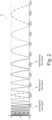
- FIG. 2 illustrates 18 separate frequency bands provided by an exemplary embodiment of the WARP filter bank 12.
- the low-frequency band signal 14 may be obtained by summing outputs of several of the warped filters for example bands 2, 3 and 4 such that the low-frequency band signal 14 comprises frequencies of the incoming sound between about 100 - 1000 Hz, more preferably between 200 - 600 Hz. Adjacent frequencies are attenuated according to the roll-off rate or steepness of the warped bands.
- the high-frequency band signal 18 may be obtained by summing outputs of several of other of the warped filter bands for example bands 14, 15 and 16 such that the high-frequency band signal 18 comprises frequencies of the incoming sound between about 4 - 8 kHz such between 5 - 7 kHz.
- the optional mid-frequency band signal 16 may comprise frequencies between 1000 - 4 kHz such between 1.2 - 3.9 kHz and obtained by summing outputs of the warped bands 11, 12 and 13.
- the skilled person will appreciate that the splitting of the digital microphone signal into the above-outlined separate low-frequency, high-frequency and mid-frequency bands ensures that the low-frequency band contains dominant frequencies of voiced/plosive speech onsets while the high-frequency band contains dominant frequencies of unvoiced speech.
- the mid-frequency band preferably contains the frequency range or region with the least dominant speech harmonics.
- the speech detector 10 additionally comprises respective signal envelope detectors 20 for the low-frequency band signal 14, mid-frequency band signal 16 and high-frequency band signal 18 to derive or determine respective power envelope signals as discussed in additional detail below.
- the speech detector 10 further comprises three noise estimators or detectors 22 that derive various noise power envelopes, clean power envelopes and certain envelope ratios from each of the power envelope signals as discussed in additional detail below.
- Outputs of the three noise estimators or detectors 22 are inputted to respective fast onset detectors 24 that monitors the presence the fast onsets across the low-frequency, mid-frequency and high-frequency bands. The latter results are applied to respective inputs of a fast onset distribution detector 26.
- the computed fast onset distributions are finally applied to a probability estimator 28 which is configured to increase or decrease a value of a speech probability and on that basis flag or indicate to the DSP 8 the presence of speech in the incoming sound as discussed in additional detail below.
- FIG. 3 shows a schematic block diagram of various intermediate signal processing functions or steps, in particular estimation or determination of certain envelope ratios, carried out by the speech detector 10 on each of the low-frequency band signal 14, mid-frequency band signal 16 and the high-frequency band signal 18.
- the DSP 8 extracts, computes or determines a low-frequency, or first, power envelope or power envelope signal 301 of the frequency band signal in question, e.g. the low-frequency band signal 14.
- the first power envelope signal 301 may for example be determined by performing non-linear averaging of the first frequency band signal 14 in step/function 20 - for example by lowpass filtering the first frequency band signal 16 using an attack time between 0 and 10 ms and a release time between 20 ms and 100 ms such as between 20 ms and 35 ms.
- This non-linear averaging may be viewed as lowpass filtering using a lowpass filter with one forgetting factor, i.e. corresponding to the attack time, if or when the first frequency band signal 14 exceeds an output of the lowpass filter and another forgetting factor, i.e. corresponding to the release time, when the first frequency band signal 14 is smaller than the filter output (release).
- the DSP 8 additionally extracts, computes or determines a high-frequency, or second, power envelope signal of the high-frequency band signal 18 in a corresponding manner and may be using identical, or alternatively somewhat shorter, attack and release times in view of the higher frequency components or content of the high-frequency band signal 18.
- the latter times may comprise an attack time between 0 and 5 ms and a release time between 5 ms and 35 ms.
- the DSP 8 may optionally extract, compute or determine a mid-frequency, or third, power envelope signal of the mid-frequency band signal 16 in a corresponding manner and may be using identical or somewhat shorter attack and release times for the non-linear averaging of the mid-frequency band signal 16 compared to those of the low-frequency band signal 18.
- the DSP 8 extracts, computes or determines various power envelope signals that are utilized for detection or identification of certain fast speech onsets within each of the low-frequency band, high-frequency band and mid-frequency band.
- the DSP 8 extracts, computes or determines a so-called low-frequency, or first, stationary noise power signal based on the low-frequency power envelope signal.
- the DSP 8 additionally extracts, computes or determines a high-frequency, or second, stationary noise power signal based on the high-frequency power envelope signal in a corresponding manner.
- the DSP 8 may finally extract, compute or determine a mid-frequency, or third stationary noise power signal based on the mid-frequency power envelope signal in a corresponding manner. This process or mechanism is schematically illustrated on FIG.
- step/function 302 carries out computation of the low-frequency, high-frequency and mid-frequency stationary noise power signals 303 based on the respective ones of the low-frequency, high-frequency and mid-frequency power envelope signals 301 provided by step/function 20.
- the computation of these low-frequency, high-frequency and mid-frequency stationary noise power signals 303 serve to provide an accurate estimate of the background noise power level in, or of, the incoming sound as represented by the digital microphone signal or signals.
- Each of the low-frequency, high-frequency and mid-frequency stationary noise power signals 303 may comprise an aggressive stationary noise power signal 303 as discussed below in additional detail.
- the speech detector 10 may be configured to determine the aggressive stationary noise power signals 303 (stn estimates) for the corresponding power envelope signals 301 as schematically illustrated by a signal flowchart 600 of FIG. 6 , by:
- the stationary noise power signal or estimate estimates a noise floor of incoming sound within the frequency band signal in question.
- the stationary noise power signal can be understood as tracking a minimum noise power in the relevant frequency band signal.
- the present aggressive stationary noise signal or estimate 303 fluctuates markedly more than a traditional stationary noise power estimate.
- the present aggressive stationary noise signal or estimate 303 is configured to estimate power of the power envelope signal 301 just before an increase in power to estimate power of a new onset as discussed in additional detail below in connection with the computation of the non-stationary noise power signal 307.
- All states are preferably initialized at zero.
- the speech detector 10 proceeds by function 302 to subtract the aggressive stationary noise power signal 303 from the power envelope signal 301 to generate the above-mentioned power envelope signal without stationary noise 304 (stnEstPowEnv) in each of the frequency bands.
- the power envelope signal without stationary noise 304 may be viewed as the frequency band signal in question cleaned from stationary noise.
- the power envelope signal without, i.e. cleaned from, stationary noise 304 is applied to the input of a block/function 306 which additionally extracts, computes or determines the so-called low-frequency, or first, non-stationary noise power signal or estimate 307.
- the speech detector 10 additionally extracts, computes or determines a high-frequency, or second, non-stationary noise power signal or estimate 307 based on the high-frequency power envelope signal 301 in a corresponding manner and optionally computes a mid-frequency, or third, non-stationary noise power signal 307 based on the mid-frequency power envelope signal 301 in a corresponding manner.
- the respective roles of the aggressive stationary noise power signal 303, non-stationary noise power signal or estimate 307 and clean power signal or estimate 313 of a particular frequency band signal may be understood by considering a frequency band signal, derived from the incoming sound, which includes a mixture of sound sources comprising a stationary noise source, a non-stationary noise source and target speech.
- the stationary noise power signal indicates or tracks the noise floor of the frequency band signal and, hence, a true stationary noise power.
- This true stationary noise power also corresponds to a minimum value of the aggressive stationary noise power signal 303.
- the frequency band signal, and the corresponding power envelope signal 301 comprises or encounters a non-stationary noise "jump” or "bump"
- an ordinary stationary noise power estimate will remain substantially constant and not influenced by the non-stationary noise "jump” or "bump”.
- the present aggressive stationary noise power signal 303 will, after the onset of the non-stationary noise "jump” or “bump” has died out become equal to a total noise in the frequency band signal. Now assume that a speech onset takes place after the non-stationary noise "jump” or "bump” has died out.
- the best estimate of the power of that speech onset is obtained by a difference of the power of the frequency band signal just before the speech onset, which was tracked by the aggressive stationary noise power signal 303, and the power after the speech onset has died out. So the aggressive stationary noise power signal 303 provides the speech detector with an estimate of the total power increase of the frequency band signal caused by each new jump in power.
- Each of the non-stationary noise power signals 307 may be determined or computed by block 306 of the speech detector using signal processing steps schematically illustrated on the flowchart on FIG. 7 .
- the speech detector in response to the value of stnRemovedPowerEnvelope exceeds the non-stationary noise power signal 307, the speech detector jumps to step 720.
- an estimated increase in the non-stationary noise power signal or estimate 307 is set equal to a forgetting factor times the power envelope signal 301 minus the aggressive stationary noise power signal 303; where the forgetting factor corresponds to a settling time of about 30 to 40 msec.
- the non-stationary noise power signal 307 (nstn estimate) is set equal to max(0, min(stnRemovedPowerEnvelope minus stnRemovedPowerEnvelopePrev, the non-stationary noise power signal 307 + estimated increase (delta) in the non-stationary noise power signal 307));
- the clean power signal or estimate 313 is determined as the power envelope signal 301 minus the aggressive stationary noise power signal 303 minus the non-stationary noise power signal 307 as depicted on FIG. 3 .
- step 710 in response to the value of stnRemovedPowerEnvelope is smaller than the non-stationary noise power signal 307, the speech detector jumps to step 715 wherein the non-stationary noise power signal or estimate 307 (nstn) is set equal to the value of stnRemovedPowerEnvelope; the speech detector proceeds to step 730 and determines the clean power signal or estimate 313 as the power envelope signal 301 minus the aggressive stationary noise power signal 303, corresponding to signal 304 and from latter subtracts the non-stationary noise power signal or estimate 307 as depicted on FIG. 3 if the optional down-slope smoothing function 310 is disregarded or omitted as discussed below.
- All states or variables are preferably initialized at zero.
- the associated clean power signal 313 is generated by subtracting the associated aggressive stationary noise power signal 303 and the, optional, associated non-stationary noise power signal 307 from the power envelope signal 301.
- the computation of these non-stationary noise power signals is optional but may serve to obtain accurate estimates of the first, second and third clean power signals 313 and ultimately increase the accuracy of the speech detection.
- the speech detector 10 is configured or programmed to proceed by computing certain peak-to minimum power envelope factors or ratios in the low-frequency, mid-frequency and high-frequency bands.
- the speech detector preferably exploit one or more of these peak-to minimum power envelope ratios power envelope ratios to identify or indicate voiced speech onsets and unvoiced speech onsets in the incoming sound. More specifically, the speech detector 10 is preferably configured to, in step 316, determine the low-frequency power envelope ratio by determining a low-frequency, i.e. first, crest factor or ratio 317 using the crest block or function 316 by dividing the low-frequency clean power signal 313 and low-frequency aggressive stationary noise power signal 303.
- the speech detector 10 may be configured to compute high-frequency and mid-frequency crest ratios 317 in a corresponding manner based on the respective high-frequency and mid-frequency clean power signals 313 and aggressive stationary noise power signals 303.
- the skilled person will appreciate that each of the crest ratios 317 may be indicative of a peakiness of the corresponding power envelope signal 301 after removal of all stationary noise components and non-stationary noise components.
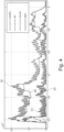
- FIG. 4 illustrates the results of the above-mentioned power envelope determinations in the low-frequency band for an exemplary noisy speech signal over a time span or segment of about 500 ms.
- Plot 301 is the determined low-frequency power envelope signal
- plot 303 is the low-frequency aggressive stationary noise power signal
- plot 307 is the low-frequency non-stationary noise power signal
- plot 313 is the corresponding low-frequency clean power signal 313. It is evident that the low-frequency clean power signal 313 largely only contains fast envelope power jumps or fluctuations.
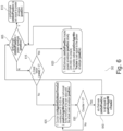
- FIG. 5 is a schematic flow chart of signal processing steps carried out by an exemplary embodiment of the fast onset detectors 26 of the speech detector 10 (refer to FIG. 1 ) executed on the DSP to compute a speech probability estimator based on indications of voiced speech onsets and unvoiced speech onsets in the low-frequency and high-frequency bands, respectively.
- the speech detector 10 utilizes the above-discussed low-frequency, high-frequency and optionally the mid-frequency power envelope signals 301, the low-frequency, high-frequency and mid-frequency aggressive stationary noise power signals 303, the low-frequency, high-frequency and mid-frequency non-stationary noise power signals 307 and the low-frequency, high-frequency and mid-frequency clean power signals 313.
- step or function 510 the speech detector 10 initially determines a low-frequency, or first, fast onset probability, fastOnsetProb_1, associated with the low-frequency band signal based on the crest ratio 317 of that frequency band.
- the speech detector 10 preferably additionally determines corresponding high-frequency and/or mid-frequency fast onset probabilities using similar thresholding mechanisms as outlined above.
- the threshold value crestThIdMin may lie between 1.5 and 3.5 and the value of threshold crestThIdMax may lie between 1.8 and 4.
- the respective values of crestThIdMin and crestThIdMax may vary between the low-frequency, high-frequency and mid-frequency bands or may be substantially identical across these frequency bands.
- the specific threshold values may in some embodiments lie between 3 and 3.3 in the low-frequency band and 2.2 and 2.5 in the mid-frequency band and high-frequency band.
- variable fastOnsetProb_1 of the low-frequency band, mid-frequency band or high-frequency band is set a value of one (1).
- the fast onset may be flagged or categorized as a fast onset directly in response to the variable fastOnsetProb_1 is one or may alternatively be subjected to further tests before the fast onset is categorized as an onset of voiced speech in the incoming sound or as an onset of unvoiced speech in the incoming sound.
- the speech detector 10 may during processing step 520 for example categorize the fast onset as an impulse sound, as opposed to speech sound or component, if multiple fast onsets are detected concurrently in the low-frequency and high-frequency power envelope signals 301. Likewise, the speech detector 10 may in function or step 520 categorize the fast onset as an impulse sound, as opposed to speech sound or component, if the duration of each of the multiple fast onsets is less than a predetermined time period, or duration threshold, such as 0.05 s (50 ms). This is because it is a priori known that typical voiced speech components have longer duration than the duration threshold. If one or both of these criteria are fulfilled, the detected fast onset may safely be categorized as impulse sound or sounds and the speech detector 10 may accordingly decrease the value of the speech probability estimator 550 via the illustrated connection or wire 541.
- a predetermined time period, or duration threshold such as 0.05 s (50 ms). This is because it is a priori known that typical voiced speech components have longer duration than the duration threshold
- the speech detector 10 may categorize the fast onset as a voiced speech onset on the condition multiple fast onsets mainly are detected in the low-frequency power envelope signal 301 and increase the value of the speech probability estimator 550.
- the speech detector 10 may categorize the fast onset as a probable onset of unvoiced speech if the multiple fast onsets are mainly detected in the high-frequency power envelope signal and/or mainly detected in the mid-frequency power envelope signal and increase the value of the speech probability estimator 550.
- the speech detector 10 may categorize the fast onset as a voiced speech onset on the condition that the power or energy of the low-frequency clean power signal following the fast onset is significantly larger, e.g. at least 2 to 3 times larger, than the power or energy of the high-frequency clean power signal following the fast onset.
- the processing step or function 530 of the speech detector enables the speech detector 510 to make that determination by tracking or computing the respective maximum clean powers of the low-frequency, high-frequency and mid-frequency clean power signals 313 following a fast onset in any of the frequency bands.
- the speech detector 10 preferably exclusively increases the value of the speech probability estimator 550 if that latter criterion/condition is fulfilled.
- the speech detector 10 may categorize a fast onset in the high-frequency band signal as an unvoiced speech onset on the condition that the power or energy of the high-frequency clean power signal following the fast onset is significantly larger than the power or energy low-frequency clean power signal. Optionally in addition larger than the power or energy of the mid-frequency clean power signal, following the fast onset .
- the speech detector 10 preferably only increases the value of the speech probability estimator 550 via the illustrated connection or wire 542 in response to compliance with the latter criterion/condition.
- the speech detector 10 preferably decreases the value of the speech probability estimator 550 via the illustrated input variable over wire 542.
- the speech probability estimator 550 complies with a certain, or pre-set, speech criterion such as a value of the speech probability estimator exceeds a predetermined threshold.
- the DSP 8 may use the speech flag or signal 32 to adjust one or more parameters of one or several signal processing algorithm(s), for example the previously discussed environmental classifier algorithm, noise reduction algorithm, speech enhancement algorithm etc., executed on the portable communication device by the DSP 8.
- the speech detector 10 is configured to increase or decrease the value of speech probability estimator 550 via the input connections 541, 542, 543 based on the respective indications of voiced speech onsets and unvoiced speech onsets derived from the low-frequency, high-frequency and mid-frequency power envelope signals 301.
- the skilled person will appreciate that the respective detections of the unvoiced speech onsets and voiced speech onsets in the respective frequency band signals can be viewed as analysis or monitoring of a modulation spectrum of speech of the incoming sound.
Landscapes
- Engineering & Computer Science (AREA)
- Signal Processing (AREA)
- Physics & Mathematics (AREA)
- Acoustics & Sound (AREA)
- Computational Linguistics (AREA)
- Health & Medical Sciences (AREA)
- Audiology, Speech & Language Pathology (AREA)
- Human Computer Interaction (AREA)
- Multimedia (AREA)
- Quality & Reliability (AREA)
- Telephone Function (AREA)
- Mobile Radio Communication Systems (AREA)
Claims (17)
- Procédé de détection de parole d'un son entrant au niveau d'un dispositif de communication portable, comprenant :- générer un signal de microphone par un agencement de microphone du dispositif de communication portable en réponse au son entrant,- diviser le signal de microphone en une pluralité de signaux de bande de fréquence séparés comprenant au moins un premier signal de bande de fréquence adapté à la détection des débuts de parole voisée et un second signal de bande de fréquence adapté à la détection des débuts de parole non voisée,- déterminer un premier signal d'enveloppe de puissance du premier signal de bande de fréquence et un second signal d'enveloppe de puissance du second signal de bande de fréquence,- dériver un premier signal de puissance de bruit stationnaire et un premier signal de puissance de bruit non stationnaire à partir du premier signal d'enveloppe de puissance,- dériver un premier signal de puissance propre en soustrayant le premier signal de puissance de bruit stationnaire et le premier signal de puissance de bruit non stationnaire du premier signal d'enveloppe de puissance,- dériver un second signal de puissance de bruit stationnaire et un second signal de puissance de bruit non stationnaire à partir du second signal d'enveloppe de puissance,- dériver un second signal de puissance propre en soustrayant le second signal de puissance de bruit stationnaire et le second signal de puissance de bruit non stationnaire à partir du deuxième signal d'enveloppe de puissance,- déterminer les débuts de parole voisée dans le premier signal de bande de fréquences sur la base du premier signal de puissance de bruit stationnaire et du premier signal de puissance propre,- déterminer les débuts de parole non voisée dans le deuxième signal de bande de fréquences sur la base du deuxième signal de puissance de bruit stationnaire et du deuxième signal de puissance propre,- augmenter ou diminuer une valeur d'un estimateur de probabilité de parole sur la base des débuts déterminés de parole voisée et des débuts déterminés de parole non voisée.
- Procédé de détection de parole selon la revendication 1, dans lequel- la détermination des débuts de parole voisée dans le premier signal de bande de fréquence est basée sur une première valeur de crête représentative d'une puissance ou d'une énergie relative entre le premier signal de puissance propre et le premier signal de puissance de bruit stationnaire, ladite première valeur de crête étant par exemple obtenue en divisant le premier signal de puissance propre et le premier signal de puissance de bruit stationnaire,- la détermination des débuts de parole non voisée dans le second signal de bande de fréquence est basée sur une seconde valeur de crête représentative d'une puissance ou d'une énergie relative entre le second signal de puissance propre et le second signal de puissance de bruit stationnaire, ladite seconde valeur de crête étant par exemple obtenue en divisant le second signal de puissance propre et le second signal de puissance de bruit stationnaire.
- Procédé de détection de la parole selon l'une quelconque des revendications précédentes, comprenant en outre :- déterminer le premier signal d'enveloppe de puissance en effectuant un calcul de moyenne non linéaire du premier signal de bande de fréquence, par exemple en filtrant par passe-bas le premier signal de bande de fréquence en utilisant un premier temps d'attaque et un premier temps de relâchement tel qu'un premier temps d'attaque compris entre 0 et 10 ms et un premier temps de relâchement compris entre 20 et 100 ms ; et- déterminer le second signal d'enveloppe de puissance en comprenant :- effectuer un calcul de moyenne non linéaire du second signal de bande de fréquence, par exemple en filtrant par passe-bas le second signal de bande de fréquence en utilisant un second temps d'attaque et un second temps de relâchement tel qu'un second temps d'attaque compris entre 0 et 10 ms et un second temps de relâchement compris entre 20 et 100 ms.
- Procédé de détection de parole selon la revendication 3, comprenant en outre :- déterminer une première probabilité d'apparition rapide, fastOnsetProb_1 , du signal de première bande de fréquence en comparant la première valeur de crête à des valeurs de seuil minimales et maximales prédéfinies - par exemple selon : fastOnsetProb_1 = min(1, max(0, (crest - crestThldMin) / (crestThldMax - crestThldMin))); et/ou- déterminer une seconde probabilité d'apparition rapide, fastOnsetProb_2, du signal de seconde bande de fréquence en comparant la seconde valeur de crête à des valeurs de seuil minimales et maximales prédéfinies par exemple selon : fastOnsetProb_2 = min(1, max(0, (crest - crestThldMin) / (crestThldMax - crestThldMin))).
- Procédé de détection de parole selon la revendication 4, dans lequel une valeur de crestThldMin est comprise entre 1,5 et 3,5 et une valeur de crestThldMax ia entre 1,8 et 4.
- Procédé de détection de parole selon la revendication 5, comprenant en outre :- indiquer l'apparition d'un début rapide dans le premier signal de bande de fréquence en réponse à la première probabilité de début rapide, fastOnsetProb_1 , qui atteint une valeur de un, - déterminer une durée du début rapide dans le premier signal de bande de fréquence,- comparer la durée du début rapide à un premier seuil de durée, tel que 50 ms,- si la durée du début rapide dans le premier signal de bande de fréquence dépasse le premier seuil de durée en réponse : catégoriser le début rapide comme un début de parole et augmenter la valeur de l'estimateur de probabilité de parole ; sinon,- catégoriser le début rapide comme une impulsion et maintenir ou diminuer la valeur de l'estimateur de probabilité de parole.
- Procédé de détection de la parole selon la revendication 6, comprenant en outre :- en réponse à l'apparition rapide dans la première bande de fréquences, le signal est catégorisé comme apparition de la parole :- déterminer si la puissance du premier signal de puissance propre suivant l'apparition rapide est significativement supérieure à la puissance du second signal de puissance propre du second signal de bande de fréquence suivant l'apparition rapide, et si cela est satisfait, augmenter la valeur de l'estimateur de probabilité de la parole ; sinon : - maintenir ou diminuer la valeur de l'estimateur de probabilité de la parole.
- Procédé de détection de parole selon la revendication 6 ou 7, comprenant en outre :- indiquer l'apparition d'un début rapide dans le signal de seconde bande de fréquence en réponse à la seconde probabilité de début rapide, fastOnsetProb_1, qui atteint une valeur de un,- déterminer une durée du début rapide dans le signal de seconde bande de fréquence,- comparer la durée du début rapide au premier seuil de durée, tel que 50 ms,- si la durée du début rapide dans le signal de seconde bande de fréquence dépasse le premier seuil de durée en réponse : catégoriser le début rapide comme un début de parole et augmenter la valeur de l'estimateur de probabilité de parole ; sinon,- catégoriser le début rapide comme une impulsion et maintenir ou diminuer la valeur de l'estimateur de probabilité de parole.
- Procédé de détection de la parole selon la revendication 8, comprenant en outre :- en réponse au début rapide dans la seconde bande de fréquences, le signal est catégorisé comme début de parole :- déterminer si la puissance du second signal de puissance propre suivant le début rapide dans la seconde bande de fréquences est significativement supérieure à la puissance du premier signal de puissance propre du premier signal de bande de fréquences suivant le début rapide ; et si cela est satisfait, augmenter la valeur de l'estimateur de probabilité de la parole ; sinon : maintenir ou diminuer la valeur de l'estimateur de probabilité de la parole.
- Procédé de détection de la parole selon la revendication 8 ou 9, comprenant en outre :- déterminer si plusieurs débuts rapides sont indiqués simultanément dans les premier et second signaux de bande de fréquences et si tel est le cas, catégoriser les débuts rapides dans les premier et second signaux de bande de fréquences comme des sons impulsionnels ; et- maintenir ou diminuer la valeur de l'estimateur de probabilité de la parole.
- Procédé de détection de la parole selon la revendication 10, comprenant en outre, dans le cas où plusieurs débuts rapides ne sont pas indiqués simultanément dans les signaux de première et seconde bande de fréquence :- classer les débuts rapides dans les signaux de première et seconde bande de fréquence comme débuts de parole voisée et de parole non voisée, respectivement ; et- augmenter la valeur de l'estimateur de probabilité de parole.
- Procédé de détection de la parole selon l'une quelconque des revendications 7 à 11, comprenant :- détecter un premier instant dans le temps pour l'apparition du début rapide dans le signal de première bande de fréquence et détecter un second instant dans le temps pour l'apparition du début rapide dans le signal de seconde bande de fréquence,- déterminer une différence de temps entre les premier et second instants dans le temps,- comparer la différence de temps à un seuil de temps prédéterminé tel que 2 s ou 1 s ; et- augmenter la valeur de l'estimateur de probabilité de parole si la différence de temps est inférieure au seuil de temps prédéterminé ; sinon,- maintenir ou diminuer la valeur de l'estimateur de probabilité de parole.
- Procédé de détection de la parole selon l'une quelconque des revendications 2 à 12, dans lequel la détermination du premier signal de puissance de bruit stationnaire agressif comprend :- le suivi du premier signal d'enveloppe de puissance à l'aide d'un premier temps d'attaque d'enveloppe lorsque le premier signal d'enveloppe de puissance est supérieur au premier signal de puissance de bruit stationnaire agressif, et d'un premier temps de libération d'enveloppe lorsque le premier signal d'enveloppe de puissance est inférieur ou égal au premier signal de puissance de bruit stationnaire agressif, ledit temps d'attaque d'enveloppe dépassant 500 ms et ledit premier temps de libération d'enveloppe étant inférieur à 50 ms, par exemple inférieur à 1 s.
- Procédé de détection de la parole selon l'une quelconque des revendications 2 à 13, dans lequel la détermination du premier signal de puissance de bruit non stationnaire comprend :- le suivi d'une différence entre le premier signal d'enveloppe de puissance et le premier signal de puissance de bruit stationnaire à l'aide d'un temps d'attaque lorsque la différence est supérieure au premier signal de puissance de bruit non stationnaire, et d'un temps de relâchement lorsque la différence est inférieure ou égale au premier signal de puissance de bruit non stationnaire, ledit temps d'attaque étant de préférence compris entre 20 ms et 100 ms et ledit temps de relâchement étant de préférence compris entre 0 ms et 10 ms, par exemple entre 0,1 ms et 8 ms,- la limitation d'une augmentation maximale du premier signal de puissance de bruit non stationnaire à une valeur inférieure ou égale à un maximum de zéro et une augmentation d'une différence entre le premier signal d'enveloppe de puissance et le premier signal de puissance de bruit stationnaire,- la détermination d'une première différence d'enveloppe, par exemple par soustraction, du premier signal de puissance de bruit stationnaire agressif du premier signal de puissance de bruit non stationnaire lorsque ce dernier est positif, et- réglage du premier signal de puissance de bruit non stationnaire à zéro lorsque la première différence d'enveloppe est négative.
- Procédé de détection de la parole selon l'une quelconque des revendications précédentes, comprenant en outre :- comparaison de l'estimateur de probabilité de la parole à un critère de parole prédéterminé, tel qu'un seuil prédéterminé ; et- indication de la parole dans le son entrant conforme au critère de parole prédéterminé ; et éventuellement ajustement d'une valeur de paramètre d'algorithme de traitement de signal exécuté sur le dispositif de communication portable par exemple par un microprocesseur et/ou un DSP.
- Détecteur de parole configuré, adapté ou programmé pour recevoir et traiter le son entrant conformément au procédé de détection de la parole selon l'une quelconque des revendications 1 à 15.
- Dispositif de communication portable, tel qu'un dispositif auditif porté sur la tête comme une prothèse ou un instrument auditif, comprenant un détecteur de parole selon la revendication 16.
Priority Applications (1)
| Application Number | Priority Date | Filing Date | Title |
|---|---|---|---|
| EP25153170.3A EP4528732A3 (fr) | 2020-02-04 | 2021-02-04 | Procédé de détection de la parole et détecteur de parole pour des rapports signal/bruit faibles |
Applications Claiming Priority (2)
| Application Number | Priority Date | Filing Date | Title |
|---|---|---|---|
| EP20155485 | 2020-02-04 | ||
| PCT/EP2021/052676 WO2021156375A1 (fr) | 2020-02-04 | 2021-02-04 | Procédé de détection de parole et détecteur de parole pour rapports signal sur bruit faibles |
Related Child Applications (1)
| Application Number | Title | Priority Date | Filing Date |
|---|---|---|---|
| EP25153170.3A Division EP4528732A3 (fr) | 2020-02-04 | 2021-02-04 | Procédé de détection de la parole et détecteur de parole pour des rapports signal/bruit faibles |
Publications (3)
| Publication Number | Publication Date |
|---|---|
| EP4100949A1 EP4100949A1 (fr) | 2022-12-14 |
| EP4100949B1 true EP4100949B1 (fr) | 2025-01-22 |
| EP4100949C0 EP4100949C0 (fr) | 2025-01-22 |
Family
ID=69468493
Family Applications (2)
| Application Number | Title | Priority Date | Filing Date |
|---|---|---|---|
| EP25153170.3A Pending EP4528732A3 (fr) | 2020-02-04 | 2021-02-04 | Procédé de détection de la parole et détecteur de parole pour des rapports signal/bruit faibles |
| EP21702507.1A Active EP4100949B1 (fr) | 2020-02-04 | 2021-02-04 | Procédé de détection de la parole et détecteur de la parole pour faibles rapports signal/bruit |
Family Applications Before (1)
| Application Number | Title | Priority Date | Filing Date |
|---|---|---|---|
| EP25153170.3A Pending EP4528732A3 (fr) | 2020-02-04 | 2021-02-04 | Procédé de détection de la parole et détecteur de parole pour des rapports signal/bruit faibles |
Country Status (3)
| Country | Link |
|---|---|
| US (2) | US12131749B2 (fr) |
| EP (2) | EP4528732A3 (fr) |
| WO (1) | WO2021156375A1 (fr) |
Families Citing this family (3)
| Publication number | Priority date | Publication date | Assignee | Title |
|---|---|---|---|---|
| US20230267945A1 (en) * | 2020-08-12 | 2023-08-24 | Dolby International Ab | Automatic detection and attenuation of speech-articulation noise events |
| CN114464212B (zh) * | 2021-08-30 | 2025-07-04 | 西安荣耀终端有限公司 | 一种音频信号的杂音检测方法及相关电子设备 |
| CN118840993B (zh) * | 2024-08-08 | 2025-11-07 | 宁波方太厨具有限公司 | 主动降噪系统及其控制方法、异音检测方法、装置 |
Family Cites Families (7)
| Publication number | Priority date | Publication date | Assignee | Title |
|---|---|---|---|---|
| US7277554B2 (en) | 2001-08-08 | 2007-10-02 | Gn Resound North America Corporation | Dynamic range compression using digital frequency warping |
| FI20045315L (fi) * | 2004-08-30 | 2006-03-01 | Nokia Corp | Ääniaktiivisuuden havaitseminen äänisignaalissa |
| US9215527B1 (en) * | 2009-12-14 | 2015-12-15 | Cirrus Logic, Inc. | Multi-band integrated speech separating microphone array processor with adaptive beamforming |
| CN103262577B (zh) * | 2010-12-08 | 2016-01-06 | 唯听助听器公司 | 助听器和增强语音重现的方法 |
| US9964433B2 (en) * | 2011-02-09 | 2018-05-08 | The Trustees Of Dartmouth College | Acoustic sensor with an acoustic object detector for reducing power consumption in front-end circuit |
| US9570093B2 (en) * | 2013-09-09 | 2017-02-14 | Huawei Technologies Co., Ltd. | Unvoiced/voiced decision for speech processing |
| US9532131B2 (en) * | 2014-02-21 | 2016-12-27 | Apple Inc. | System and method of improving voice quality in a wireless headset with untethered earbuds of a mobile device |
-
2021
- 2021-02-04 WO PCT/EP2021/052676 patent/WO2021156375A1/fr not_active Ceased
- 2021-02-04 EP EP25153170.3A patent/EP4528732A3/fr active Pending
- 2021-02-04 EP EP21702507.1A patent/EP4100949B1/fr active Active
-
2022
- 2022-05-31 US US17/828,777 patent/US12131749B2/en active Active
-
2024
- 2024-07-08 US US18/766,553 patent/US20240363136A1/en active Pending
Also Published As
| Publication number | Publication date |
|---|---|
| US12131749B2 (en) | 2024-10-29 |
| EP4528732A2 (fr) | 2025-03-26 |
| WO2021156375A1 (fr) | 2021-08-12 |
| US20240363136A1 (en) | 2024-10-31 |
| US20220293127A1 (en) | 2022-09-15 |
| EP4528732A3 (fr) | 2025-05-14 |
| EP4100949A1 (fr) | 2022-12-14 |
| EP4100949C0 (fr) | 2025-01-22 |
Similar Documents
| Publication | Publication Date | Title |
|---|---|---|
| US20240363136A1 (en) | Method of detecting speech and speech detector for low signal-to-noise ratios | |
| EP0326905B1 (fr) | Système d'élaboration de signaux pour prothèse auditive | |
| JP6328627B2 (ja) | 雑音検出及びラウドネス低下検出によるラウドネスコントロール | |
| CN102282867B (zh) | 助听器和一种检测并衰减瞬变的方法 | |
| US8290190B2 (en) | Method for sound processing in a hearing aid and a hearing aid | |
| US10614788B2 (en) | Two channel headset-based own voice enhancement | |
| US7876918B2 (en) | Method and device for processing an acoustic signal | |
| EP2747081A1 (fr) | Dispositif de traitement audio comprenant une réduction d'artéfacts | |
| EP3360136B1 (fr) | Système d'aide auditive et procédé de fonctionnement d'un système d'aide auditive | |
| US11240609B2 (en) | Music classifier and related methods | |
| US9082411B2 (en) | Method to reduce artifacts in algorithms with fast-varying gain | |
| WO2016089745A1 (fr) | Appareil et procédé de traitement de signal numérique avec des microphones | |
| WO2015078501A1 (fr) | Procédé pour faire fonctionner un système de prothèse auditive, et système de prothèse auditive | |
| US10251002B2 (en) | Noise characterization and attenuation using linear predictive coding | |
| US9992583B2 (en) | Hearing aid system and a method of operating a hearing aid system | |
| EP3704870B1 (fr) | Procédé de traitement d'un signal d'entrée acoustique (vocal), et dispositif de traitement audio | |
| Ngo et al. | An integrated approach for noise reduction and dynamic range compression in hearing aids | |
| CN121217069A (zh) | 一种基于削波检测算法的音频增益调整方法及其相关设备 | |
| HK1208290B (en) | Loudness control with noise detection and loudness drop detection |
Legal Events
| Date | Code | Title | Description |
|---|---|---|---|
| STAA | Information on the status of an ep patent application or granted ep patent |
Free format text: STATUS: UNKNOWN |
|
| STAA | Information on the status of an ep patent application or granted ep patent |
Free format text: STATUS: THE INTERNATIONAL PUBLICATION HAS BEEN MADE |
|
| PUAI | Public reference made under article 153(3) epc to a published international application that has entered the european phase |
Free format text: ORIGINAL CODE: 0009012 |
|
| STAA | Information on the status of an ep patent application or granted ep patent |
Free format text: STATUS: REQUEST FOR EXAMINATION WAS MADE |
|
| 17P | Request for examination filed |
Effective date: 20220902 |
|
| AK | Designated contracting states |
Kind code of ref document: A1 Designated state(s): AL AT BE BG CH CY CZ DE DK EE ES FI FR GB GR HR HU IE IS IT LI LT LU LV MC MK MT NL NO PL PT RO RS SE SI SK SM TR |
|
| DAV | Request for validation of the european patent (deleted) | ||
| DAX | Request for extension of the european patent (deleted) | ||
| GRAP | Despatch of communication of intention to grant a patent |
Free format text: ORIGINAL CODE: EPIDOSNIGR1 |
|
| STAA | Information on the status of an ep patent application or granted ep patent |
Free format text: STATUS: GRANT OF PATENT IS INTENDED |
|
| INTG | Intention to grant announced |
Effective date: 20240816 |
|
| GRAS | Grant fee paid |
Free format text: ORIGINAL CODE: EPIDOSNIGR3 |
|
| GRAA | (expected) grant |
Free format text: ORIGINAL CODE: 0009210 |
|
| STAA | Information on the status of an ep patent application or granted ep patent |
Free format text: STATUS: THE PATENT HAS BEEN GRANTED |
|
| AK | Designated contracting states |
Kind code of ref document: B1 Designated state(s): AL AT BE BG CH CY CZ DE DK EE ES FI FR GB GR HR HU IE IS IT LI LT LU LV MC MK MT NL NO PL PT RO RS SE SI SK SM TR |
|
| REG | Reference to a national code |
Ref country code: GB Ref legal event code: FG4D |
|
| REG | Reference to a national code |
Ref country code: CH Ref legal event code: EP |
|
| REG | Reference to a national code |
Ref country code: IE Ref legal event code: FG4D |
|
| REG | Reference to a national code |
Ref country code: DE Ref legal event code: R096 Ref document number: 602021025128 Country of ref document: DE |
|
| U01 | Request for unitary effect filed |
Effective date: 20250220 |
|
| U07 | Unitary effect registered |
Designated state(s): AT BE BG DE DK EE FI FR IT LT LU LV MT NL PT RO SE SI Effective date: 20250227 |
|
| U20 | Renewal fee for the european patent with unitary effect paid |
Year of fee payment: 5 Effective date: 20250516 |
|
| PG25 | Lapsed in a contracting state [announced via postgrant information from national office to epo] |
Ref country code: RS Free format text: LAPSE BECAUSE OF FAILURE TO SUBMIT A TRANSLATION OF THE DESCRIPTION OR TO PAY THE FEE WITHIN THE PRESCRIBED TIME-LIMIT Effective date: 20250422 |
|
| PG25 | Lapsed in a contracting state [announced via postgrant information from national office to epo] |
Ref country code: PL Free format text: LAPSE BECAUSE OF FAILURE TO SUBMIT A TRANSLATION OF THE DESCRIPTION OR TO PAY THE FEE WITHIN THE PRESCRIBED TIME-LIMIT Effective date: 20250122 |
|
| PG25 | Lapsed in a contracting state [announced via postgrant information from national office to epo] |
Ref country code: ES Free format text: LAPSE BECAUSE OF FAILURE TO SUBMIT A TRANSLATION OF THE DESCRIPTION OR TO PAY THE FEE WITHIN THE PRESCRIBED TIME-LIMIT Effective date: 20250122 |
|
| PGFP | Annual fee paid to national office [announced via postgrant information from national office to epo] |
Ref country code: GB Payment date: 20250422 Year of fee payment: 5 |
|
| PG25 | Lapsed in a contracting state [announced via postgrant information from national office to epo] |
Ref country code: NO Free format text: LAPSE BECAUSE OF FAILURE TO SUBMIT A TRANSLATION OF THE DESCRIPTION OR TO PAY THE FEE WITHIN THE PRESCRIBED TIME-LIMIT Effective date: 20250422 Ref country code: IS Free format text: LAPSE BECAUSE OF FAILURE TO SUBMIT A TRANSLATION OF THE DESCRIPTION OR TO PAY THE FEE WITHIN THE PRESCRIBED TIME-LIMIT Effective date: 20250522 |
|
| PG25 | Lapsed in a contracting state [announced via postgrant information from national office to epo] |
Ref country code: HR Free format text: LAPSE BECAUSE OF FAILURE TO SUBMIT A TRANSLATION OF THE DESCRIPTION OR TO PAY THE FEE WITHIN THE PRESCRIBED TIME-LIMIT Effective date: 20250122 |
|
| PG25 | Lapsed in a contracting state [announced via postgrant information from national office to epo] |
Ref country code: GR Free format text: LAPSE BECAUSE OF FAILURE TO SUBMIT A TRANSLATION OF THE DESCRIPTION OR TO PAY THE FEE WITHIN THE PRESCRIBED TIME-LIMIT Effective date: 20250423 |
|
| PGFP | Annual fee paid to national office [announced via postgrant information from national office to epo] |
Ref country code: CH Payment date: 20250515 Year of fee payment: 5 |
|
| PG25 | Lapsed in a contracting state [announced via postgrant information from national office to epo] |
Ref country code: SM Free format text: LAPSE BECAUSE OF FAILURE TO SUBMIT A TRANSLATION OF THE DESCRIPTION OR TO PAY THE FEE WITHIN THE PRESCRIBED TIME-LIMIT Effective date: 20250122 |
|
| PG25 | Lapsed in a contracting state [announced via postgrant information from national office to epo] |
Ref country code: MC Free format text: LAPSE BECAUSE OF FAILURE TO SUBMIT A TRANSLATION OF THE DESCRIPTION OR TO PAY THE FEE WITHIN THE PRESCRIBED TIME-LIMIT Effective date: 20250122 |
|
| PG25 | Lapsed in a contracting state [announced via postgrant information from national office to epo] |
Ref country code: CZ Free format text: LAPSE BECAUSE OF FAILURE TO SUBMIT A TRANSLATION OF THE DESCRIPTION OR TO PAY THE FEE WITHIN THE PRESCRIBED TIME-LIMIT Effective date: 20250122 |
|
| PG25 | Lapsed in a contracting state [announced via postgrant information from national office to epo] |
Ref country code: SK Free format text: LAPSE BECAUSE OF FAILURE TO SUBMIT A TRANSLATION OF THE DESCRIPTION OR TO PAY THE FEE WITHIN THE PRESCRIBED TIME-LIMIT Effective date: 20250122 |
|
| PLBE | No opposition filed within time limit |
Free format text: ORIGINAL CODE: 0009261 |
|
| STAA | Information on the status of an ep patent application or granted ep patent |
Free format text: STATUS: NO OPPOSITION FILED WITHIN TIME LIMIT |
|
| 26N | No opposition filed |
Effective date: 20251023 |
|
| PG25 | Lapsed in a contracting state [announced via postgrant information from national office to epo] |
Ref country code: IE Free format text: LAPSE BECAUSE OF NON-PAYMENT OF DUE FEES Effective date: 20250204 |