EP4100855B1 - Apparatus and method for capability-based processing - Google Patents
Apparatus and method for capability-based processing Download PDFInfo
- Publication number
- EP4100855B1 EP4100855B1 EP20821359.5A EP20821359A EP4100855B1 EP 4100855 B1 EP4100855 B1 EP 4100855B1 EP 20821359 A EP20821359 A EP 20821359A EP 4100855 B1 EP4100855 B1 EP 4100855B1
- Authority
- EP
- European Patent Office
- Prior art keywords
- capability
- control flow
- flow change
- address
- instruction
- Prior art date
- Legal status (The legal status is an assumption and is not a legal conclusion. Google has not performed a legal analysis and makes no representation as to the accuracy of the status listed.)
- Active
Links
Images





Classifications
-
- G—PHYSICS
- G06—COMPUTING OR CALCULATING; COUNTING
- G06F—ELECTRIC DIGITAL DATA PROCESSING
- G06F12/00—Accessing, addressing or allocating within memory systems or architectures
- G06F12/02—Addressing or allocation; Relocation
- G06F12/08—Addressing or allocation; Relocation in hierarchically structured memory systems, e.g. virtual memory systems
- G06F12/10—Address translation
- G06F12/1027—Address translation using associative or pseudo-associative address translation means, e.g. translation look-aside buffer [TLB]
-
- G—PHYSICS
- G06—COMPUTING OR CALCULATING; COUNTING
- G06F—ELECTRIC DIGITAL DATA PROCESSING
- G06F12/00—Accessing, addressing or allocating within memory systems or architectures
- G06F12/14—Protection against unauthorised use of memory or access to memory
- G06F12/1458—Protection against unauthorised use of memory or access to memory by checking the subject access rights
-
- G—PHYSICS
- G06—COMPUTING OR CALCULATING; COUNTING
- G06F—ELECTRIC DIGITAL DATA PROCESSING
- G06F21/00—Security arrangements for protecting computers, components thereof, programs or data against unauthorised activity
- G06F21/50—Monitoring users, programs or devices to maintain the integrity of platforms, e.g. of processors, firmware or operating systems
- G06F21/52—Monitoring users, programs or devices to maintain the integrity of platforms, e.g. of processors, firmware or operating systems during program execution, e.g. stack integrity ; Preventing unwanted data erasure; Buffer overflow
-
- G—PHYSICS
- G06—COMPUTING OR CALCULATING; COUNTING
- G06F—ELECTRIC DIGITAL DATA PROCESSING
- G06F21/00—Security arrangements for protecting computers, components thereof, programs or data against unauthorised activity
- G06F21/60—Protecting data
- G06F21/604—Tools and structures for managing or administering access control systems
-
- G—PHYSICS
- G06—COMPUTING OR CALCULATING; COUNTING
- G06F—ELECTRIC DIGITAL DATA PROCESSING
- G06F9/00—Arrangements for program control, e.g. control units
- G06F9/06—Arrangements for program control, e.g. control units using stored programs, i.e. using an internal store of processing equipment to receive or retain programs
- G06F9/30—Arrangements for executing machine instructions, e.g. instruction decode
- G06F9/30003—Arrangements for executing specific machine instructions
- G06F9/3005—Arrangements for executing specific machine instructions to perform operations for flow control
-
- G—PHYSICS
- G06—COMPUTING OR CALCULATING; COUNTING
- G06F—ELECTRIC DIGITAL DATA PROCESSING
- G06F9/00—Arrangements for program control, e.g. control units
- G06F9/06—Arrangements for program control, e.g. control units using stored programs, i.e. using an internal store of processing equipment to receive or retain programs
- G06F9/30—Arrangements for executing machine instructions, e.g. instruction decode
- G06F9/30098—Register arrangements
- G06F9/30105—Register structure
-
- G—PHYSICS
- G06—COMPUTING OR CALCULATING; COUNTING
- G06F—ELECTRIC DIGITAL DATA PROCESSING
- G06F9/00—Arrangements for program control, e.g. control units
- G06F9/06—Arrangements for program control, e.g. control units using stored programs, i.e. using an internal store of processing equipment to receive or retain programs
- G06F9/30—Arrangements for executing machine instructions, e.g. instruction decode
- G06F9/32—Address formation of the next instruction, e.g. by incrementing the instruction counter
- G06F9/321—Program or instruction counter, e.g. incrementing
-
- G—PHYSICS
- G06—COMPUTING OR CALCULATING; COUNTING
- G06F—ELECTRIC DIGITAL DATA PROCESSING
- G06F9/00—Arrangements for program control, e.g. control units
- G06F9/06—Arrangements for program control, e.g. control units using stored programs, i.e. using an internal store of processing equipment to receive or retain programs
- G06F9/30—Arrangements for executing machine instructions, e.g. instruction decode
- G06F9/32—Address formation of the next instruction, e.g. by incrementing the instruction counter
- G06F9/322—Address formation of the next instruction, e.g. by incrementing the instruction counter for non-sequential address
-
- G—PHYSICS
- G06—COMPUTING OR CALCULATING; COUNTING
- G06F—ELECTRIC DIGITAL DATA PROCESSING
- G06F9/00—Arrangements for program control, e.g. control units
- G06F9/06—Arrangements for program control, e.g. control units using stored programs, i.e. using an internal store of processing equipment to receive or retain programs
- G06F9/30—Arrangements for executing machine instructions, e.g. instruction decode
- G06F9/32—Address formation of the next instruction, e.g. by incrementing the instruction counter
- G06F9/322—Address formation of the next instruction, e.g. by incrementing the instruction counter for non-sequential address
- G06F9/327—Address formation of the next instruction, e.g. by incrementing the instruction counter for non-sequential address for interrupts
-
- G—PHYSICS
- G06—COMPUTING OR CALCULATING; COUNTING
- G06F—ELECTRIC DIGITAL DATA PROCESSING
- G06F9/00—Arrangements for program control, e.g. control units
- G06F9/06—Arrangements for program control, e.g. control units using stored programs, i.e. using an internal store of processing equipment to receive or retain programs
- G06F9/30—Arrangements for executing machine instructions, e.g. instruction decode
- G06F9/34—Addressing or accessing the instruction operand or the result ; Formation of operand address; Addressing modes
- G06F9/35—Indirect addressing
Definitions
- This disclosure relates to apparatus and methods.
- Some examples of data processing apparatus handle processes in which memory access is determined by so-called capability data.
- pointers are augmented with metadata to represent specific access restrictions and/or permissions.
- a first capability applicable to execution of the first code portion should allow access to the first code portion, so that there is a need to make a change to a second capability (allowing access to the second code portion) in order to implement the control flow change.
- One way of achieving this would be store, for example as literal data in the first code portion, data for use to define the second capability. This then requires at least two operations to implement the control flow change: an operation to load the data and to apply it as a new capability; and an operation to implement the control flow change itself.
- US 2018/0225120 A1 provides an apparatus and method for controlling instruction execution behaviour.
- the apparatus includes a set of data registers for storing data values, and a set of bounded pointer storage elements, where each bounded pointer storage element stores a pointer having associated range information indicative of an allowable range of addresses when using that pointer.
- a control storage element stores a current instruction context, and that current instruction context is used to influence the behaviour of at least one instruction executed by processing circuitry, that at least one instruction specifying a pointer reference for a required pointer, where the pointer reference is within at least a first subset of values (in one embodiment the behaviour is influenced irrespective of the value of the required pointer).
- the processing circuitry uses the pointer reference to identify one of the data registers whose stored data value forms the required pointer.
- the processing circuitry instead uses the pointer reference to identify one of the bounded pointer storage elements whose stored pointer forms the required pointer. This allows an instruction set to be provided that can be used for both bounded pointer aware code and bounded pointer unaware code, without significantly increasing the pressure on instruction set encoding space.
- apparatus comprising: a processor to execute program instructions stored at respective memory addresses, processing of the program instructions being constrained by a prevailing capability defining at least access permissions to a set of one or more memory addresses; the processor comprising:
- a computer program for controlling a host data processing apparatus to provide an instruction execution environment comprising:
- An example embodiment provides apparatus comprising: a processor to execute program instructions stored at respective memory addresses, processing of the program instructions being constrained by a prevailing capability defining at least access permissions to a set of one or more memory addresses; the processor comprising:
- suitable capability information to allow a capability to be constructed or generated for use as a capability configured to constrain processing of one or more instructions for execution after the control flow change operation) is provided at an address defined with respect to the control flow change target address. This advantageously allows the capability data to be stored only once and can provide for a more efficient change of capability at a control flow change.
- control flow change target address might indicate the address of a next program instruction for execution after the control flow change operation.
- branch delay slots may be used, such that a branch does not necessarily take immediate effect.
- the instruction that is executed next after a branch instruction is just the instruction after the branch in the memory, and not necessarily the instruction at the target address of the branch. In the case where a single branch delay slot is used, control would move to the branch target address after the instruction after the branch in memory.
- the capability generating circuitry may be configured to generate the pointer in dependence upon the control flow change target address and to generate the data defining access permissions to the set of memory addresses in dependence upon the capability access permissions data.
- the whole of a capability may be stored with respect to the target address.
- the capability access permissions data defines one or more of (i) a lower limit memory address of an address region comprising the one or more memory addresses to which access is permitted, (ii) an upper limit memory address of the address region and (iii) a set of permission attributes applicable to the address region.
- the capability access permissions data defines a location at which information defining access permissions to the set of memory addresses is stored.
- the execution of (at least) the first instruction following the flow change can be performed in parallel with (or at least overlapping) the generation of the new capability.
- the processor in response to the control flow change operation the processor may be configured to set a status indicator, to indicate that the capability generating circuitry is required to generate the capability for use as the next prevailing capability.
- the processor in response to the status indicator being set, the processor may be configured to fetch and/or execute at least the first instruction at the control flow change target address independently of constraint by a prevailing capability.
- the status indicator may be cleared once the new capability is ready, in which case the processor may be configured, in response to generation of the capability for use as the next prevailing capability, to clear the status indicator to a state indicating that processing of program instructions is constrained by a prevailing capability. To allow this status to be maintained and recovered in the case of an intervening exception, in some examples the processor is configured, in response to a processing exception event to store the status indicator for retrieval upon processing of an exception return event.
- the generation of the new capability may be completed before it is needed for execution of the first instruction in which case the one or more instructions for execution after the control flow change operation include at least an instruction at the control flow change target address.
- the first instruction can be at the target address, in which case the control flow change handling circuitry is configured to determine the address at which capability access permissions data is stored as a memory address preceding the control flow change target address.
- control flow change operation is a branch operation in response to execution of a branch instruction, which may comprise an operation code which defines at least the control flow change target address by encoding within the operation code a value indicative of a difference from an instruction address of the branch instruction.
- operation code may define at least a register identifier that identifies a register containing a value indicative of the control flow change target address.
- control flow change operation may be a branch and link operation in response to execution of a branch and link instruction, in which case the branch and link operation may store a return address capability, the return address capability being generated in dependence on the instruction address of the branch and link instruction and the prevailing capability in use when the branch and link instruction was executed.
- control flow change operation may define a change of control flow to a processing exception handling routine.
- the processor may be configured to identify an entry in a vector table in memory in dependence on a number associated with the exception handling routine to be processed, wherein at least part of the entry is indicative of the control flow change target address, and at least part of the entry may be indicative of whether the exception handling routine is to be processed independently of constraint by a prevailing capability (for example, the vector table could indicate just the target address, and the question of whether the exception handler uses capabilities could be determined elsewhere; for example it may always use capabilities, or there may be a single configuration bit that controls how all exceptions are handled).
- a further example of a control flow change operation comprises an exception return operation to return from processing such an exception handling routine.
- Figure 1 schematically illustrates an example of a data processing apparatus or processor 2 comprising a processing pipeline 4 for processing instructions.
- the processing pipeline 4 includes a number of pipeline stages including a fetch stage 6, a decode stage 8, an issue stage 10, an execute stage or processing element 12, and a write back stage 14, but it will be appreciated that other types or combinations of stages may be provided.
- a rename stage for performing register renaming could be included in some implementations. Instructions to be processed move from stage to stage, and while an instruction is pending at one stage another instruction may be pending at a different stage of the pipeline 4.
- the fetch stage 6 fetches instructions from a level 1 (L1) instruction cache 20.
- the fetch stage 6 may usually fetch instructions sequentially from successive instruction addresses.
- the fetch stage may also have a branch predictor 22 for predicting the outcome of branch instructions, and the fetch stage 6 can fetch instructions from a (non-sequential) branch target address if the branch is predicted to be taken, or from the next sequential address if the branch is predicted not to be taken.
- the branch predictor 22 may include one or more branch history tables for storing information for predicting whether certain branches are likely to be taken or not.
- the branch history tables may include counters for tracking the actual outcomes of previously executed branches or representing confidence in predictions made for branches.
- the branch predictor 22 may also include a branch target address cache (BTAC) 24 for caching previous target addresses of branch instructions so that these can be predicted on subsequent encounters of the same branch instructions.
- BTAC branch target address cache
- the fetched instructions are passed to the decode stage 8 which decodes the instructions to generate decoded instructions.
- the decoded instructions may comprise control information for controlling the execute stage 12 to execute the appropriate processing operations.
- the decode stage 8 may map those instructions to multiple decoded instructions, which may be known as micro-operations (pops or uops).
- micro-operations pops or uops
- references to "instructions" in the present application should be interpreted as including micro-operations.
- the decoded instructions are passed to the issue stage 10, which determines whether operands required for execution of the instructions are available and issues the instructions for execution when the operands are available.
- Some implementations may support in-order processing so that instructions are issued for execution in an order corresponding to the program order in which instructions were fetched from the L1 instruction cache 20.
- Other implementations may support out-of-order execution, so that instructions can be issued to the execute stage 12 in a different order from the program order. Out-of-order processing can be useful for improving performance because while an earlier instruction is stalled while awaiting operands, a later instruction in the program order whose operands are available can be executed first. It will be appreciated that in other embodiments the issue stage 10 may be combined with other stages, or eliminated altogether, at the cost of performance.
- the issue stage 10 issues the instructions to the execute stage 12 where the instructions are executed to carry out various data processing operations.
- the execute stage may include a number of execute units 30, 32, 33, 34 including an arithmetic/logic unit (ALU) 30 for carrying out arithmetic or logical operations on integer values, a floating-point (FP) unit 32 for carrying out operations on values represented in floating-point form, a control flow change handling unit or circuitry 33 to perform a control flow change operation (in one example this unit embodies the function of a branch instruction execution unit to determine the actual outcome of the branch operation), and a load/store unit 34 for carrying out load operations for loading a data value from a level 1 (L1) data cache 36 to a register within a set of general purpose data registers 40 or store operations for storing a data value from a register within the set of general purpose data registers 40 to the L1 data cache 36.
- ALU arithmetic/logic unit
- FP floating-point
- FP floating-point
- FP floating-
- the level 1 data cache 36 may not be present and the load/store unit 34 may access memory directly.
- the execute stage 12 may read data values from a set of registers 40. Results of the executed instructions may then be written back to the registers 40 by the write back stage 14.
- the L1 instruction cache 20 and L1 data cache 36 may be part of a cache hierarchy including multiple levels of caches.
- a level two (L2) cache 44 may also be provided and optionally further levels of cache could be provided.
- the L2 cache 44 is shared between the L1 instruction cache 20 and L1 data cache 36 but other examples may have separate L2 instruction and data caches.
- L1 instruction cache 20 When an instruction to be fetched is not in the L1 instruction cache 20 then it can be fetched from the L2 cache 44 and similarly if the instruction is not in the L2 cache 44 then it can be fetched from main memory 50.
- data can be fetched from the L2 cache 44 if it is not in the L1 data cache 36 and fetched from memory 50 if required. Any known scheme may be used for managing the cache hierarchy.
- the addresses used by the pipeline 4 to refer to program instructions and data values may be virtual addresses, but at least the main memory 50, and optionally also at least some levels of the cache hierarchy and/or memory 50, may be physically addressed.
- a translation lookaside buffer 52 (TLB) may be provided, under the control of a memory management unit (MMU) 53 for translating the virtual addresses used by the pipeline 4 into physical addresses used for accessing the cache or memory.
- MMU memory management unit
- the TLB 52 may include a number of entries each specifying a virtual page address ("VPA") of a corresponding page of the virtual address space and a corresponding physical page address ("PPA”) to which the virtual page address should be mapped in order to translate the virtual addresses within the corresponding page to physical addresses.
- VPN virtual page address
- PPA physical page address
- each TLB entry may also include some information ("perm") specifying access permissions such as indicating whether certain pages of addresses are accessible in certain modes of the pipeline 4.
- the TLB entries could also define other properties of the corresponding page of addresses, such as cache policy information defining which levels of the cache hierarchy are updated in response to read or write operations (e.g.
- MPU 53 and TLB 52 may not exist and the instructions executed by the data processing apparatus 2 may directly access physical addresses.
- access permissions and cache policy information may instead be provided by a memory protection unit (MPU) 54 that contains registers that specify the information relating to a range of addresses in physical memory.
- MPU memory protection unit
- FIG. 1 shows a single level TLB 52
- a hierarchy of translation may be provided by the MMU 53 and/or that multiple TLBs may be provided so that a level one (L1) TLB 52 may include TLB entries for translating addresses in a number of recently accessed pages and a level two (L2) TLB may be provided for storing entries for a larger number of pages.
- L1 TLB level one
- L2 TLB level two
- IPA intermediate physical address
- IPA intermediate physical address
- multiple levels of address translation can be used so that, for example, a first TLB (or hierarchy of TLBs) may be used to translate virtual addresses into intermediate addresses, and a second level of address translation using one or more further TLB(s) may then translate the intermediate addresses into physical addresses used to access a cache or memory.
- a first TLB or hierarchy of TLBs
- a second level of address translation using one or more further TLB(s) may then translate the intermediate addresses into physical addresses used to access a cache or memory.
- This can be useful for supporting virtualisation where the first level of address translation may be managed by the operating system and the second level of address translation may be managed by the hypervisor, for example.
- a page table walk can be performed by the MMU 53 to access so-called page tables in the memory 50. Any known TLB management scheme can be used in the present technique.
- the execute stage 12 can be implemented by a multi-threaded processing element to execute one or more processing threads.
- the apparatus 2 may have a set of bounded pointer registers 60. Whilst the set of bounded pointer registers is shown in Figure 1 as being physically separate to the set of general purpose data registers 40, in one implementation the same physical storage may be used to provide both the general purpose data registers and the bounded pointer registers.
- Each bounded pointer register 60 includes a pointer value 62 that may be used to determine an address of a data value to be accessed, and range information 64 specifying an allowable range of addresses when using the corresponding pointer 62.
- the bounded pointer register 60 may also include restrictions information 66 (also referred to as permissions information) which may define one or more restrictions/permissions on the use of the pointer.
- restrictions information 66 also referred to as permissions information
- a validity tag (for example a 65 th bit in the case of a 64 bit bounded pointer register, or a 129 th bit in the case of a 128 bit bounded pointer) can be used to indicate whether (a) a valid bounded pointer is stored and (b) the range and permission metadata are valid.
- the tag is able to be set only by hardware in response to a proper capability-setting instruction, and in at least some example is automatically unset in response to any attempt to write illegally to a valid capability.
- the restriction 66 could be used to restrict the types of instructions which may use the pointer 62, or the modes of the pipeline 4 in which the pointer can be used.
- the range information 64 and restriction information 66 may be considered to define capabilities C 0 -C M-1 within which the respective pointers 62 are allowed to be used.
- the range information 64 can be useful for example for ensuring that pointers remain within certain known bounds and do not stray to other areas of the memory address space which might contain sensitive or secure information.
- the pointer value 62 may for example be stored within the same storage location as used for a corresponding general purpose register.
- Figure 2 shows an example of types of instructions for which the allowable range is used to protect against unauthorised access to data or instructions.
- a particular bounded pointer register PR1 includes a given pointer value 62 and range information 64, which in this example is specified using a lower bound address 68 defining the lower bound of the allowable range and an upper bound address 69 defining the upper bound of the allowable range.
- the bounds 68, 69 are set to define a range of addresses 80000 to 81000. Errors may be triggered when certain instructions reference the bounded pointer register PR1 and the address determined from the pointer 62 is outside this range. It will be appreciated that the bounds can be represented in a variety of different formats.
- the upper and lower bounds could be expressed with respect to the pointer value and/or in a floating point representation.
- Such formats may enable the size of the bounds information to be reduced with respect to a "raw" size of upper and lower limit address information, or in other words the bounds information may be expressed more efficiently (using fewer bits) while still defining upper and lower limit addresses.
- an error may be triggered if there is an attempt to set the value of the pointer 62 in the pointer register 60 to a value lying outside the range specified by the range information 64 (here it being assumed that the pointer directly specifies an address). This avoids the pointer 62 taking any value outside the specified range so that any accesses using the pointer can be ensured to lie safely within the allowed range.
- an error can be triggered when an instruction attempts to access a location identified by the address of the pointer 62 when that address lies outside the specified range.
- the range information 64 could be set in different ways and the manner by way it is set is an implementation detail and the present techniques do not depend on the specific method used. Purely as examples, privileged instructions, user-space code, secure code, or an operating system or hypervisor, may specify the range allowed for a given pointer.
- the instruction set architecture may include a number of instructions for setting or modifying the range information 64 for a given pointer 62, and execution of these instructions could be restricted to certain software or certain modes or exception states of the processor 2. Any known technique for setting or modifying the range information 64 could be used.
- a program counter capability (PCC) register 80 may also be used to provide similar functionality at the fetch stage 6 when instructions are being fetched from the level one instruction cache 20.
- a program counter pointer may be stored in a field 82, with the PCC 80 also providing range information 84 and any appropriate restriction information 86, similar to the range and restriction information provided with each of the pointers in the set of bounded pointer storage elements 60.
- Figure 1 also schematically illustrates a Default Data Capability (DDC) register 90 and a System Access Capability (SAC) register 95, both to be discussed below.
- DDC Default Data Capability
- SAC System Access Capability
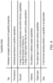
- FIG. 3 schematically illustrates how a tag bit of the type mentioned above is used in association with individual data blocks to identify whether those data blocks represent a capability (i.e. a bounded pointer and associated restrictions information), or represent normal data.
- the memory address space 110 will store a series of data blocks 115, which typically will have a specified size.
- each data block comprises 128 bits.
- a tag field 120 which in one example is a single bit field referred to as the tag bit, which is set to identify that the associated data block represents a valid capability, and is cleared to indicate that the associated data block represents normal data, and hence cannot be treated as a capability.
- the actual value associated with the set or the clear state can vary dependent on implementation, but purely by way of illustration, in one example implementation if the tag bit has a value of 1, it indicates that the associated data block is a capability, and if it has a value of 0 it indicates that the associated data block contains normal data.
- the tag bit moves with the capability information. Accordingly, when a capability is loaded into the capability register 100, the pointer 102, range information 104 and restrictions information 106 (hereafter referred to as the permissions information) will be loaded into the capability register. In addition, in association with that capability register, or as a specific bit field within it, the tag bit 108 will be set to identify that the contents represent a capability. Similarly, when a capability is stored back out to memory, the relevant tag bit 120 will be set in association with the data block in which the capability is stored. By such an approach, it is possible to distinguish between a capability and normal data, and hence ensure that normal data cannot be used as a capability.
- Capability registers are used to hold capabilities and define extensions to the memory system so that capability properties are enforced when a capability is held in general purpose memory. Instructions can be provided to load and store capabilities from memory, use capability registers to access data and capabilities in memory, to branch using a capability and to manipulate capabilities held in capability registers without forging new rights.
- PCC bounds and permissions may be updated using capability branch and return instructions and on exception entry and return.
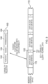
- Figure 5 schematically illustrates an example of a control flow change operation.
- control flow change operation is a branch operation (in response to execution of a branch instruction) in which a branch instruction 500, 510 causes a change in program flow from a respective first (or "calling") code portion 505, 515 to a control flow change target address 522 indicating the start of (or other predetermined location within) a target or "callee” code portion 520.
- control may return to the calling or originating code portion (505, 515 as the case may be).
- This latter feature may be implemented in some examples by using a so-called branch-with-link operation in which a return address to the originating code (in fact to the next instruction address after the branch instruction in some embodiments) is retained, for example as part of the control flow change operation the return address may be stored on a stack data structure or in a link register within the set of general purpose data registers 40.
- the return address may be a return address capability which contains in addition to the return address, contains capability to use as the prevailing capability upon to the originating code. The return capability may be derived from the prevailing capability in use at the point the branch-with-link operation was performed.
- Execution of the code portion 505 is performed in accordance with a prevailing first capability giving access permission, for the processing of program instructions, to a first range 508 of memory addresses, for example encompassing the whole of the code portion 505.
- the code portion 515 is processed under constraints defined by a capability giving access to memory addresses 518.
- a different capability 528 (as a new or next prevailing capability) giving access permission to memory addresses containing the code portion 520, is required.
- a previously proposed technique for achieving this was to execute instructions associated with the branch instruction 500, 510 to load data stored within the calling code portion 505, 515 into a respective capability register.
- Such data may be stored as so-called literal data, for example at the end (the lower portion as drawn) of the respective code portion.
- this can require additional instructions and also requires storage space at each possible instance of a calling function.
- Such a technique can also create a performance bottleneck as the capability must be loaded before the target address of the branch can be determined. This can in turn, slow down execution of the instructions at the target code portion 520.
- Another example of a control flow change operation is taking an exception.
- the generated capability is installed or otherwise established as that next prevailing capability. In some examples, it takes effect from the first instruction of the callee code. In other examples, one or more first instructions of the callee code may be processed independently of a prevailing capability in the meantime.
- control flow change operation may involve:
- references to constraint by a prevailing capability relate to the setting of the PCC in response to capability data associated with execution of particular code portions.
- the capability is checked at instruction fetch to determine whether permission exists to access the address to be fetched. If not, then an exception or fault may be initiated.
- the branch predictor 22 oversees the fetching process such that an instruction relating to a branch target address (or indeed another control flow change target address) may be fetched at a stage (in time) before the branch is resolved.
- instructions may be executed out of order, again such that instructions may be physically fetched from addresses before capabilities relating to those addresses are in place.
- pipelining, caching and other techniques may alter the physical manner in which instructions are processed, generally with the aim of improving efficiency of processing.
- An instruction set architecture can provide for processing of a common set of instructions by an in-order processor, an out-of-order processor, processors with and without speculative or predictive fetching or execution, processors with and without pipelines and the like.
- the final results and the overall machine outcome will be the same in each case; it is just that the efficiency of the internal processing may be different.
- the speculative state is maintained (which may include maintaining fault situations as speculative) for as long as is required to allow compliance with the architectural requirements.
- the microarchitecture or physical structure may maintain the illusion of operation in accordance with the architecture by keeping the results of faults in speculative state, then if the committed architecture state reaches a point where a speculative fault occurred then the fault moves from being a speculative fault to being an actual fault, and is actually taken. If on the other hand if another event causes a the architecture state to go in a different direction (for example in the case of a branch miss prediction) then the pending speculative fault is flushed as the event that caused the speculative fault should never have happened in the first place.
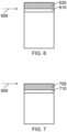
- Figures 6 and 7 schematically illustrate the technique for storing capability access permissions data with respect to the address 600 indicated by the control flow change operation (for example, a branch target address) as the control flow change target address.
- the address 600 indicates the location of the first instruction 610 to be executed after the control flow change operation, with the capability access permissions data 620 (shown shaded in Figures 6 and 7 ) being stored immediately preceding the address 600.
- the capability access permissions data 620 is 32 bits long, it would be stored in the 32 bits of memory immediately preceding the address 600.
- the one or more instructions for execution after the control flow change operation include at least an instruction at the control flow change target address
- the capability access permissions data 700 is stored at the address 600, with the first instruction 710 to be executed after the control flow change operation (an instruction 710) immediately following the stored capability access permissions data 700.
- the first instruction 710 would be stored at an address 32 bits after the address 700.
- control flow change handling circuitry is configured to determine the address at which capability access permissions data is stored as a memory address at the control flow change target address.
- Figure 8 provides a schematic overview of control flow change handling circuitry 33 as mentioned in Figure 1 , which comprises a control flow change handler 800 and capability generating circuitry 810.
- a control flow change target address 900 (such as a branch target address) is detected by an address detector 910, and in response to this the address detector 910 determines the location of the capability access permissions data (capability metadata).
- This determination may be as simple as "an address equal to the control flow change target address" in the example of Figure 7 , or may be "an address offset by a predetermined difference from the address 900" in the example of Figure 6 , for example "address 900 minus 32 bits".
- a metadata loader 920 loads the capability access permissions data 930.
- a capability generator 940 generates a capability. Examples of this operation will be described below with reference to Figures 10 and 11 but in some examples, the capability generator 940 may concatenate the loaded metadata 930 and the target address 900, optionally with a tag, to produce a valid capability which is stored as a capability 950 by storage circuitry 960.
- the storage circuitry 960 may store the generated capability 960 to the PCC 80.
- the generated capability 950 is provided for use as a next prevailing capability, for example to constrain processing of one or more instructions for execution after the control flow change operation.
- a capability 1000 is constructed by the capability generator 940 as a concatenation of the metadata 930 and a pointer 935 derived from the target address 900.
- a tag bit 1010 to indicate that this is a valid capability may be added by the capability generation circuitry 940 (noting that tag bits are allowed to be stored under the control of hardware responsive to valid instructions).
- the metadata 930 includes a tag bit 1020 so that after the concatenation the resulting capability 1100 is stored including the tag bit.
- the concatenation with a pointer derived from the control flow change target address 900 implies that the capability access permissions data can be smaller than a regular capability, needing only to provide that part of a capability not represented by the pointer portion itself. In the present example, this implies that the capability access permissions data can be only 32 (or 33) bits rather than the full size of a capability which (in this example) is 65 bits. Therefore, there is a potential saving in storage using this technique. Since the capability metadata 930 may only be stored once per code portion 520, there may be additional savings in storage space if the code portion is called from multiple locations, for example 500 and 510 in Figure 5 .
- each capability comprises at least a pointer and data defining access permissions to the set of memory addresses; and the capability generating circuitry is configured to generate the pointer in dependence upon the control flow change target address and to generate the data defining access permissions to the set of memory addresses in dependence upon the capability access permissions data.
- the capability access permissions data defines one or more of (i) a lower limit memory address of an address region comprising the one or more memory addresses to which access is permitted, (ii) an upper limit memory address of the address region and (iii) a set of permission attributes applicable to the address region.
- the capability access permissions data may instead define a location at which information defining access permissions to the set of memory addresses is stored.
- Figures 12 to 14 concern timing considerations relating to the generation of the capability in the manner discussed above.
- Figure 12 is a schematic timeline from an architectural point of view (in which instruction execution is atomic, such that an instruction is viewed as either having been executed or not having been executed, and boundaries between instructions being indicated schematically by vertical lines as drawn), with time running 1200 from left to right, illustrating one example of the generation of a capability from the capability access permissions data.
- instruction execution is atomic, such that an instruction is viewed as either having been executed or not having been executed, and boundaries between instructions being indicated schematically by vertical lines as drawn
- time running 1200 from left to right
- common microarchitecture techniques such as pipelining and out of order execution (as discussed earlier) may change actual ordering of events, but such techniques will preserve the illusion of architectural ordering shown in Figure 12 .
- a schematic block 1210 represents the processes performed to generate the next capability (for example to constrain processing of one or more instructions for execution after the control flow change operation), and a schematic box 1220 represents the actual processing of a first instruction after the control flow change operation.
- the control flow change operation itself is indicated by a schematic box 1230 on the timeline.
- control flow change handling unit of Figure 8 is supplemented by storage 1300 to store a status indicator, which may be generated by the control flow change handler 800, as discussed below.
- the processor in response to the control flow change operation, is configured to set a status indicator, to indicate that the capability generating circuitry 810 is required to generate the capability for use as a next prevailing capability.
- the processor is configured to fetch and/or execute at least the first instruction at the control flow change target address independently of constraint by a prevailing capability. Note that in some example embodiments, notwithstanding the use of this technique, such an instruction may still be executed within the constraints of the new capability, but the use of the status indicator can allow at least the instruction fetch of that instruction to go ahead in advance of the capability being available.
- the processor for example, the control flow change handler 800
- the processor is configured to clear the status indicator to a state indicating that processing of program instructions is constrained by a prevailing capability.
- Figure 14 schematically illustrates another version of the timeline (again from an architectural point of view) of Figure 12 , but in this example, after initiation 1400 of the control flow change operation, execution 1410 of at least the first instruction can proceed (under the conditions defined by the status indicator 1300) in an overlapping manner with the generation 1420 of the new capability, that is to say the capability to constrain processing of one or more instructions for execution after the control flow change operation.
- Figure 15 schematically illustrates another example of control flow changes from an architectural point of view.
- time runs from left to right and a branch operation 1500 occurs at a time indicated by the respective arrow.
- the branch operation forms one example of a control flow change operation.
- a processor interrupt or other exception event takes place.
- This further program flow change occurs in the example of Figure 15 before the execution of the first instruction after the original control flow change operation is performed.
- processor state information prior to the time 1510 is stored, for example by being pushed onto a processor stack.
- the status flag may be cleared at a time 1570 at the end of the generation of the new capability and (in this example) the execution of the first instruction.
- control flow change operation may also (or in other examples, instead) define a change of control flow to a processing exception handling routine and/or an exception return operation to return from processing an exception handling routine.
- Each exception "type” has an associated number or index. Examples may include reset, system call exceptions, interrupt request, various types of fault and the like. Each exception type has an associated number (for example, between 0 and 15) which is generated by the exception handling circuitry 9 ( Figure 1 ) in response to external or internal conditions indicating an exception situation.
- the processor is configured to identify an entry in a "vector table" in memory in dependence on a number associated with the exception handling routine to be processed, wherein at least part of the entry is indicative of the control flow change target address.
- the control flow change handler 800 then controls a change of program flow, using the techniques discussed above, to that control flow change target address. As discussed above, this can involve saving prevailing processor status information, for example to a processor stack, for retrieval upon processing of an exception return operation. This can include as mentioned above storing the status indicator 1300 for retrieval upon processing of an exception return event.
- At least part of the entry in the vector table is indicative of whether the exception handling routine is to be processed independently of constraint by a prevailing capability. If this indication is set then (a) the processor acts upon the indication to execute the exception handling routine notwithstanding the prevailing capability, and optionally (b) the capability generating circuitry does not even attempt to generate a capability for use in respect of the exception handling routine.
- Figure 1 provides an example of apparatus comprising a processor to execute program instructions stored at respective memory addresses, processing of the program instructions being constrained by a prevailing capability defining at least access permissions to a set of one or more memory addresses; the processor comprising: control flow change handling circuitry 33 to perform a control flow change operation, the control flow change operation defining a control flow change target address indicating the address of a program instruction for execution after the control flow change operation; and capability generating circuitry 810 to determine, in dependence on the control flow change target address, an address at which capability access permissions data is stored as a memory address preceding the control flow change target address; the capability generating circuitry being configured to retrieve the capability access permissions data and to generate a capability for use as a next prevailing capability in dependence upon at least the capability access permissions data.
- the capability for use as next prevailing capability is configured to constrain processing of one or more instructions for execution after the control flow change operation.
- Figure 16 is a schematic flowchart illustrating an example method comprising:
- Figure 17 illustrates a simulator implementation that may be used to implement a simulation of the apparatus and/or methods discussed above.
- Such computer programs are often referred to as simulators, insofar as they provide a software based implementation of a hardware architecture.
- Varieties of simulator computer programs include emulators, virtual machines, models, and binary translators, including dynamic binary translators.
- a simulator implementation may run on a host processor 1730, optionally running a host operating system 1720, supporting the simulator program 1710.
- powerful processors have been required to provide simulator implementations which execute at a reasonable speed, but such an approach may be justified in certain circumstances, such as when there is a desire to run code native to another processor for compatibility or re-use reasons.
- the simulator implementation may provide an instruction execution environment with additional functionality which is not supported by the host processor hardware, or provide an instruction execution environment typically associated with a different hardware architecture.
- An overview of simulation is given in " Some Efficient Architecture Simulation Techniques", Robert Bedichek, Winter 1990 USENIX Conference, Pages 53 - 63 .
- the simulator program 1710 may be stored on a computer-readable storage medium (which may be a non-transitory medium), and provides a virtual hardware interface (instruction execution environment) to the target code 1700 (which may include applications, operating systems and a hypervisor) which is the same as the interface of the hardware architecture being modelled by the simulator program 1710.
- the program instructions of the target code 1700 including the functionality described above, may be executed from within the instruction execution environment using the simulator program 1710, so that a host computer 1730 which does not actually have the hardware features of the apparatus discussed above can emulate these features.
- Such a computer program provides an example of a computer program for controlling a host data processing apparatus to provide an instruction execution environment comprising:
- the words “configured to" are used to mean that an element of an apparatus has a configuration able to carry out the defined operation.
- a “configuration” means an arrangement or manner of interconnection of hardware or software.
- the apparatus may have dedicated hardware which provides the defined operation, or a processor or other processing device (such as a processing element as discussed above) may be programmed to perform the function.
- Configured to does not imply that the apparatus element needs to be changed in any way in order to provide the defined operation.
Landscapes
- Engineering & Computer Science (AREA)
- Theoretical Computer Science (AREA)
- Software Systems (AREA)
- Physics & Mathematics (AREA)
- General Physics & Mathematics (AREA)
- General Engineering & Computer Science (AREA)
- Computer Security & Cryptography (AREA)
- Computer Hardware Design (AREA)
- General Health & Medical Sciences (AREA)
- Bioethics (AREA)
- Health & Medical Sciences (AREA)
- Automation & Control Theory (AREA)
- Storage Device Security (AREA)
- Executing Machine-Instructions (AREA)
- Photoreceptors In Electrophotography (AREA)
- Electrotherapy Devices (AREA)
- Studio Devices (AREA)
Applications Claiming Priority (2)
| Application Number | Priority Date | Filing Date | Title |
|---|---|---|---|
| GB2001688.7A GB2591795B (en) | 2020-02-07 | 2020-02-07 | Apparatus and method |
| PCT/GB2020/053093 WO2021156589A1 (en) | 2020-02-07 | 2020-12-02 | Apparatus and method for capability-based processing |
Publications (2)
| Publication Number | Publication Date |
|---|---|
| EP4100855A1 EP4100855A1 (en) | 2022-12-14 |
| EP4100855B1 true EP4100855B1 (en) | 2024-09-25 |
Family
ID=69897027
Family Applications (1)
| Application Number | Title | Priority Date | Filing Date |
|---|---|---|---|
| EP20821359.5A Active EP4100855B1 (en) | 2020-02-07 | 2020-12-02 | Apparatus and method for capability-based processing |
Country Status (8)
| Country | Link |
|---|---|
| US (1) | US12056062B2 (he) |
| EP (1) | EP4100855B1 (he) |
| JP (1) | JP7668280B2 (he) |
| KR (1) | KR20220139917A (he) |
| CN (1) | CN115104095B (he) |
| GB (1) | GB2591795B (he) |
| IL (1) | IL294692B2 (he) |
| WO (1) | WO2021156589A1 (he) |
Families Citing this family (4)
| Publication number | Priority date | Publication date | Assignee | Title |
|---|---|---|---|---|
| GB2592069B (en) * | 2020-02-17 | 2022-04-27 | Advanced Risc Mach Ltd | Address calculating instruction |
| GB2606185B (en) * | 2021-04-28 | 2023-06-21 | Advanced Risc Mach Ltd | Technique for constraining access to memory using capabilities |
| JP7762041B2 (ja) * | 2021-11-10 | 2025-10-29 | ルネサスエレクトロニクス株式会社 | 半導体装置 |
| US20220197638A1 (en) * | 2022-03-14 | 2022-06-23 | Intel Corporation | Generating encrypted capabilities within bounds |
Family Cites Families (4)
| Publication number | Priority date | Publication date | Assignee | Title |
|---|---|---|---|---|
| JPH05151088A (ja) * | 1991-11-29 | 1993-06-18 | Toshiba Corp | 記憶システムにおける記憶保護方式およびその装置 |
| JP2007052481A (ja) * | 2005-08-15 | 2007-03-01 | Matsushita Electric Ind Co Ltd | Icカード用lsi |
| GB2541714B (en) * | 2015-08-27 | 2018-02-14 | Advanced Risc Mach Ltd | An apparatus and method for controlling instruction execution behaviour |
| GB2547249B (en) * | 2016-02-12 | 2019-09-11 | Advanced Risc Mach Ltd | An apparatus and method for generating signed bounded pointers |
-
2020
- 2020-02-07 GB GB2001688.7A patent/GB2591795B/en active Active
- 2020-12-02 US US17/759,973 patent/US12056062B2/en active Active
- 2020-12-02 JP JP2022544370A patent/JP7668280B2/ja active Active
- 2020-12-02 WO PCT/GB2020/053093 patent/WO2021156589A1/en not_active Ceased
- 2020-12-02 EP EP20821359.5A patent/EP4100855B1/en active Active
- 2020-12-02 IL IL294692A patent/IL294692B2/he unknown
- 2020-12-02 KR KR1020227030311A patent/KR20220139917A/ko active Pending
- 2020-12-02 CN CN202080095958.7A patent/CN115104095B/zh active Active
Also Published As
| Publication number | Publication date |
|---|---|
| US20230060666A1 (en) | 2023-03-02 |
| GB2591795A (en) | 2021-08-11 |
| IL294692B2 (he) | 2024-02-01 |
| GB2591795B (en) | 2022-06-01 |
| JP2023512502A (ja) | 2023-03-27 |
| CN115104095A (zh) | 2022-09-23 |
| CN115104095B (zh) | 2025-10-24 |
| KR20220139917A (ko) | 2022-10-17 |
| IL294692A (he) | 2022-09-01 |
| US12056062B2 (en) | 2024-08-06 |
| WO2021156589A1 (en) | 2021-08-12 |
| GB202001688D0 (en) | 2020-03-25 |
| EP4100855A1 (en) | 2022-12-14 |
| IL294692B1 (he) | 2023-10-01 |
| JP7668280B2 (ja) | 2025-04-24 |
Similar Documents
| Publication | Publication Date | Title |
|---|---|---|
| US10613865B2 (en) | Apparatus and method for controlling instruction execution behaviour | |
| US10528490B2 (en) | Apparatus and method for managing bounded pointers | |
| US12056062B2 (en) | Apparatus and method for capability-based processing | |
| EP3619606B1 (en) | An apparatus and method for managing use of capabilities | |
| CN110622133B (zh) | 用于管理能力域的设备及方法 | |
| CN110799939B (zh) | 用于控制指令的执行的设备与方法 | |
| EP3818447B1 (en) | Memory access control | |
| US11080058B2 (en) | Apparatus and method for controlling a change in instruction set | |
| US20240193101A1 (en) | Technique for constraining access to memory using capabilities |
Legal Events
| Date | Code | Title | Description |
|---|---|---|---|
| STAA | Information on the status of an ep patent application or granted ep patent |
Free format text: STATUS: UNKNOWN |
|
| STAA | Information on the status of an ep patent application or granted ep patent |
Free format text: STATUS: THE INTERNATIONAL PUBLICATION HAS BEEN MADE |
|
| PUAI | Public reference made under article 153(3) epc to a published international application that has entered the european phase |
Free format text: ORIGINAL CODE: 0009012 |
|
| STAA | Information on the status of an ep patent application or granted ep patent |
Free format text: STATUS: REQUEST FOR EXAMINATION WAS MADE |
|
| 17P | Request for examination filed |
Effective date: 20220805 |
|
| AK | Designated contracting states |
Kind code of ref document: A1 Designated state(s): AL AT BE BG CH CY CZ DE DK EE ES FI FR GB GR HR HU IE IS IT LI LT LU LV MC MK MT NL NO PL PT RO RS SE SI SK SM TR |
|
| DAV | Request for validation of the european patent (deleted) | ||
| DAX | Request for extension of the european patent (deleted) | ||
| GRAP | Despatch of communication of intention to grant a patent |
Free format text: ORIGINAL CODE: EPIDOSNIGR1 |
|
| STAA | Information on the status of an ep patent application or granted ep patent |
Free format text: STATUS: GRANT OF PATENT IS INTENDED |
|
| RIC1 | Information provided on ipc code assigned before grant |
Ipc: G06F 12/1027 20160101ALI20240415BHEP Ipc: G06F 9/35 20180101ALI20240415BHEP Ipc: G06F 9/32 20180101ALI20240415BHEP Ipc: G06F 9/30 20180101ALI20240415BHEP Ipc: G06F 21/52 20130101AFI20240415BHEP |
|
| INTG | Intention to grant announced |
Effective date: 20240503 |
|
| GRAS | Grant fee paid |
Free format text: ORIGINAL CODE: EPIDOSNIGR3 |
|
| GRAA | (expected) grant |
Free format text: ORIGINAL CODE: 0009210 |
|
| STAA | Information on the status of an ep patent application or granted ep patent |
Free format text: STATUS: THE PATENT HAS BEEN GRANTED |
|
| P01 | Opt-out of the competence of the unified patent court (upc) registered |
Free format text: CASE NUMBER: APP_43104/2024 Effective date: 20240723 |
|
| AK | Designated contracting states |
Kind code of ref document: B1 Designated state(s): AL AT BE BG CH CY CZ DE DK EE ES FI FR GB GR HR HU IE IS IT LI LT LU LV MC MK MT NL NO PL PT RO RS SE SI SK SM TR |
|
| REG | Reference to a national code |
Ref country code: GB Ref legal event code: FG4D |
|
| REG | Reference to a national code |
Ref country code: CH Ref legal event code: EP |
|
| REG | Reference to a national code |
Ref country code: DE Ref legal event code: R096 Ref document number: 602020038425 Country of ref document: DE |
|
| REG | Reference to a national code |
Ref country code: IE Ref legal event code: FG4D |
|
| REG | Reference to a national code |
Ref country code: LT Ref legal event code: MG9D |
|
| PG25 | Lapsed in a contracting state [announced via postgrant information from national office to epo] |
Ref country code: NO Free format text: LAPSE BECAUSE OF FAILURE TO SUBMIT A TRANSLATION OF THE DESCRIPTION OR TO PAY THE FEE WITHIN THE PRESCRIBED TIME-LIMIT Effective date: 20241225 |
|
| PG25 | Lapsed in a contracting state [announced via postgrant information from national office to epo] |
Ref country code: GR Free format text: LAPSE BECAUSE OF FAILURE TO SUBMIT A TRANSLATION OF THE DESCRIPTION OR TO PAY THE FEE WITHIN THE PRESCRIBED TIME-LIMIT Effective date: 20241226 Ref country code: FI Free format text: LAPSE BECAUSE OF FAILURE TO SUBMIT A TRANSLATION OF THE DESCRIPTION OR TO PAY THE FEE WITHIN THE PRESCRIBED TIME-LIMIT Effective date: 20240925 |
|
| PG25 | Lapsed in a contracting state [announced via postgrant information from national office to epo] |
Ref country code: BG Free format text: LAPSE BECAUSE OF FAILURE TO SUBMIT A TRANSLATION OF THE DESCRIPTION OR TO PAY THE FEE WITHIN THE PRESCRIBED TIME-LIMIT Effective date: 20240925 |
|
| PG25 | Lapsed in a contracting state [announced via postgrant information from national office to epo] |
Ref country code: LV Free format text: LAPSE BECAUSE OF FAILURE TO SUBMIT A TRANSLATION OF THE DESCRIPTION OR TO PAY THE FEE WITHIN THE PRESCRIBED TIME-LIMIT Effective date: 20240925 |
|
| PG25 | Lapsed in a contracting state [announced via postgrant information from national office to epo] |
Ref country code: RS Free format text: LAPSE BECAUSE OF FAILURE TO SUBMIT A TRANSLATION OF THE DESCRIPTION OR TO PAY THE FEE WITHIN THE PRESCRIBED TIME-LIMIT Effective date: 20241225 |
|
| REG | Reference to a national code |
Ref country code: NL Ref legal event code: MP Effective date: 20240925 |
|
| PG25 | Lapsed in a contracting state [announced via postgrant information from national office to epo] |
Ref country code: RS Free format text: LAPSE BECAUSE OF FAILURE TO SUBMIT A TRANSLATION OF THE DESCRIPTION OR TO PAY THE FEE WITHIN THE PRESCRIBED TIME-LIMIT Effective date: 20241225 Ref country code: NO Free format text: LAPSE BECAUSE OF FAILURE TO SUBMIT A TRANSLATION OF THE DESCRIPTION OR TO PAY THE FEE WITHIN THE PRESCRIBED TIME-LIMIT Effective date: 20241225 Ref country code: LV Free format text: LAPSE BECAUSE OF FAILURE TO SUBMIT A TRANSLATION OF THE DESCRIPTION OR TO PAY THE FEE WITHIN THE PRESCRIBED TIME-LIMIT Effective date: 20240925 Ref country code: GR Free format text: LAPSE BECAUSE OF FAILURE TO SUBMIT A TRANSLATION OF THE DESCRIPTION OR TO PAY THE FEE WITHIN THE PRESCRIBED TIME-LIMIT Effective date: 20241226 Ref country code: FI Free format text: LAPSE BECAUSE OF FAILURE TO SUBMIT A TRANSLATION OF THE DESCRIPTION OR TO PAY THE FEE WITHIN THE PRESCRIBED TIME-LIMIT Effective date: 20240925 Ref country code: BG Free format text: LAPSE BECAUSE OF FAILURE TO SUBMIT A TRANSLATION OF THE DESCRIPTION OR TO PAY THE FEE WITHIN THE PRESCRIBED TIME-LIMIT Effective date: 20240925 |
|
| REG | Reference to a national code |
Ref country code: AT Ref legal event code: MK05 Ref document number: 1727254 Country of ref document: AT Kind code of ref document: T Effective date: 20240925 |
|
| PG25 | Lapsed in a contracting state [announced via postgrant information from national office to epo] |
Ref country code: NL Free format text: LAPSE BECAUSE OF FAILURE TO SUBMIT A TRANSLATION OF THE DESCRIPTION OR TO PAY THE FEE WITHIN THE PRESCRIBED TIME-LIMIT Effective date: 20240925 |
|
| PG25 | Lapsed in a contracting state [announced via postgrant information from national office to epo] |
Ref country code: IS Free format text: LAPSE BECAUSE OF FAILURE TO SUBMIT A TRANSLATION OF THE DESCRIPTION OR TO PAY THE FEE WITHIN THE PRESCRIBED TIME-LIMIT Effective date: 20250125 Ref country code: PT Free format text: LAPSE BECAUSE OF FAILURE TO SUBMIT A TRANSLATION OF THE DESCRIPTION OR TO PAY THE FEE WITHIN THE PRESCRIBED TIME-LIMIT Effective date: 20250127 |
|
| PG25 | Lapsed in a contracting state [announced via postgrant information from national office to epo] |
Ref country code: SM Free format text: LAPSE BECAUSE OF FAILURE TO SUBMIT A TRANSLATION OF THE DESCRIPTION OR TO PAY THE FEE WITHIN THE PRESCRIBED TIME-LIMIT Effective date: 20240925 Ref country code: RO Free format text: LAPSE BECAUSE OF FAILURE TO SUBMIT A TRANSLATION OF THE DESCRIPTION OR TO PAY THE FEE WITHIN THE PRESCRIBED TIME-LIMIT Effective date: 20240925 |
|
| PG25 | Lapsed in a contracting state [announced via postgrant information from national office to epo] |
Ref country code: ES Free format text: LAPSE BECAUSE OF FAILURE TO SUBMIT A TRANSLATION OF THE DESCRIPTION OR TO PAY THE FEE WITHIN THE PRESCRIBED TIME-LIMIT Effective date: 20240925 |
|
| PG25 | Lapsed in a contracting state [announced via postgrant information from national office to epo] |
Ref country code: AT Free format text: LAPSE BECAUSE OF FAILURE TO SUBMIT A TRANSLATION OF THE DESCRIPTION OR TO PAY THE FEE WITHIN THE PRESCRIBED TIME-LIMIT Effective date: 20240925 Ref country code: EE Free format text: LAPSE BECAUSE OF FAILURE TO SUBMIT A TRANSLATION OF THE DESCRIPTION OR TO PAY THE FEE WITHIN THE PRESCRIBED TIME-LIMIT Effective date: 20240925 |
|
| PG25 | Lapsed in a contracting state [announced via postgrant information from national office to epo] |
Ref country code: PL Free format text: LAPSE BECAUSE OF FAILURE TO SUBMIT A TRANSLATION OF THE DESCRIPTION OR TO PAY THE FEE WITHIN THE PRESCRIBED TIME-LIMIT Effective date: 20240925 Ref country code: CZ Free format text: LAPSE BECAUSE OF FAILURE TO SUBMIT A TRANSLATION OF THE DESCRIPTION OR TO PAY THE FEE WITHIN THE PRESCRIBED TIME-LIMIT Effective date: 20240925 |
|
| PG25 | Lapsed in a contracting state [announced via postgrant information from national office to epo] |
Ref country code: SK Free format text: LAPSE BECAUSE OF FAILURE TO SUBMIT A TRANSLATION OF THE DESCRIPTION OR TO PAY THE FEE WITHIN THE PRESCRIBED TIME-LIMIT Effective date: 20240925 Ref country code: IT Free format text: LAPSE BECAUSE OF FAILURE TO SUBMIT A TRANSLATION OF THE DESCRIPTION OR TO PAY THE FEE WITHIN THE PRESCRIBED TIME-LIMIT Effective date: 20240925 |
|
| REG | Reference to a national code |
Ref country code: DE Ref legal event code: R097 Ref document number: 602020038425 Country of ref document: DE |
|
| PG25 | Lapsed in a contracting state [announced via postgrant information from national office to epo] |
Ref country code: MC Free format text: LAPSE BECAUSE OF FAILURE TO SUBMIT A TRANSLATION OF THE DESCRIPTION OR TO PAY THE FEE WITHIN THE PRESCRIBED TIME-LIMIT Effective date: 20240925 |
|
| PG25 | Lapsed in a contracting state [announced via postgrant information from national office to epo] |
Ref country code: DK Free format text: LAPSE BECAUSE OF FAILURE TO SUBMIT A TRANSLATION OF THE DESCRIPTION OR TO PAY THE FEE WITHIN THE PRESCRIBED TIME-LIMIT Effective date: 20240925 |
|
| REG | Reference to a national code |
Ref country code: CH Ref legal event code: PL |
|
| PLBE | No opposition filed within time limit |
Free format text: ORIGINAL CODE: 0009261 |
|
| STAA | Information on the status of an ep patent application or granted ep patent |
Free format text: STATUS: NO OPPOSITION FILED WITHIN TIME LIMIT |
|
| PG25 | Lapsed in a contracting state [announced via postgrant information from national office to epo] |
Ref country code: LU Free format text: LAPSE BECAUSE OF NON-PAYMENT OF DUE FEES Effective date: 20241202 |
|
| 26N | No opposition filed |
Effective date: 20250626 |
|
| PG25 | Lapsed in a contracting state [announced via postgrant information from national office to epo] |
Ref country code: SE Free format text: LAPSE BECAUSE OF FAILURE TO SUBMIT A TRANSLATION OF THE DESCRIPTION OR TO PAY THE FEE WITHIN THE PRESCRIBED TIME-LIMIT Effective date: 20240925 |
|
| REG | Reference to a national code |
Ref country code: BE Ref legal event code: MM Effective date: 20241231 |
|
| PG25 | Lapsed in a contracting state [announced via postgrant information from national office to epo] |
Ref country code: BE Free format text: LAPSE BECAUSE OF NON-PAYMENT OF DUE FEES Effective date: 20241231 |
|
| PG25 | Lapsed in a contracting state [announced via postgrant information from national office to epo] |
Ref country code: CH Free format text: LAPSE BECAUSE OF NON-PAYMENT OF DUE FEES Effective date: 20241231 |
|
| PG25 | Lapsed in a contracting state [announced via postgrant information from national office to epo] |
Ref country code: IE Free format text: LAPSE BECAUSE OF NON-PAYMENT OF DUE FEES Effective date: 20241202 |
|
| PGFP | Annual fee paid to national office [announced via postgrant information from national office to epo] |
Ref country code: DE Payment date: 20251126 Year of fee payment: 6 |
|
| PGFP | Annual fee paid to national office [announced via postgrant information from national office to epo] |
Ref country code: GB Payment date: 20251119 Year of fee payment: 6 |
|
| PG25 | Lapsed in a contracting state [announced via postgrant information from national office to epo] |
Ref country code: HR Free format text: LAPSE BECAUSE OF FAILURE TO SUBMIT A TRANSLATION OF THE DESCRIPTION OR TO PAY THE FEE WITHIN THE PRESCRIBED TIME-LIMIT Effective date: 20240925 |
|
| PGFP | Annual fee paid to national office [announced via postgrant information from national office to epo] |
Ref country code: FR Payment date: 20251119 Year of fee payment: 6 |
|
| PG25 | Lapsed in a contracting state [announced via postgrant information from national office to epo] |
Ref country code: CY Free format text: LAPSE BECAUSE OF FAILURE TO SUBMIT A TRANSLATION OF THE DESCRIPTION OR TO PAY THE FEE WITHIN THE PRESCRIBED TIME-LIMIT; INVALID AB INITIO Effective date: 20201202 |