EP4100759B1 - Réseaux de positionnement distribués élastiques - Google Patents
Réseaux de positionnement distribués élastiques Download PDFInfo
- Publication number
- EP4100759B1 EP4100759B1 EP21717254.3A EP21717254A EP4100759B1 EP 4100759 B1 EP4100759 B1 EP 4100759B1 EP 21717254 A EP21717254 A EP 21717254A EP 4100759 B1 EP4100759 B1 EP 4100759B1
- Authority
- EP
- European Patent Office
- Prior art keywords
- beacon
- multitone
- sym
- beacon signals
- network
- Prior art date
- Legal status (The legal status is an assumption and is not a legal conclusion. Google has not performed a legal analysis and makes no representation as to the accuracy of the status listed.)
- Active
Links
Images


Classifications
-
- G—PHYSICS
- G01—MEASURING; TESTING
- G01S—RADIO DIRECTION-FINDING; RADIO NAVIGATION; DETERMINING DISTANCE OR VELOCITY BY USE OF RADIO WAVES; LOCATING OR PRESENCE-DETECTING BY USE OF THE REFLECTION OR RERADIATION OF RADIO WAVES; ANALOGOUS ARRANGEMENTS USING OTHER WAVES
- G01S1/00—Beacons or beacon systems transmitting signals having a characteristic or characteristics capable of being detected by non-directional receivers and defining directions, positions, or position lines fixed relatively to the beacon transmitters; Receivers co-operating therewith
- G01S1/02—Beacons or beacon systems transmitting signals having a characteristic or characteristics capable of being detected by non-directional receivers and defining directions, positions, or position lines fixed relatively to the beacon transmitters; Receivers co-operating therewith using radio waves
- G01S1/04—Details
- G01S1/042—Transmitters
- G01S1/0428—Signal details
-
- G—PHYSICS
- G01—MEASURING; TESTING
- G01S—RADIO DIRECTION-FINDING; RADIO NAVIGATION; DETERMINING DISTANCE OR VELOCITY BY USE OF RADIO WAVES; LOCATING OR PRESENCE-DETECTING BY USE OF THE REFLECTION OR RERADIATION OF RADIO WAVES; ANALOGOUS ARRANGEMENTS USING OTHER WAVES
- G01S1/00—Beacons or beacon systems transmitting signals having a characteristic or characteristics capable of being detected by non-directional receivers and defining directions, positions, or position lines fixed relatively to the beacon transmitters; Receivers co-operating therewith
- G01S1/02—Beacons or beacon systems transmitting signals having a characteristic or characteristics capable of being detected by non-directional receivers and defining directions, positions, or position lines fixed relatively to the beacon transmitters; Receivers co-operating therewith using radio waves
- G01S1/04—Details
- G01S1/045—Receivers
-
- G—PHYSICS
- G01—MEASURING; TESTING
- G01S—RADIO DIRECTION-FINDING; RADIO NAVIGATION; DETERMINING DISTANCE OR VELOCITY BY USE OF RADIO WAVES; LOCATING OR PRESENCE-DETECTING BY USE OF THE REFLECTION OR RERADIATION OF RADIO WAVES; ANALOGOUS ARRANGEMENTS USING OTHER WAVES
- G01S5/00—Position-fixing by co-ordinating two or more direction or position line determinations; Position-fixing by co-ordinating two or more distance determinations
- G01S5/02—Position-fixing by co-ordinating two or more direction or position line determinations; Position-fixing by co-ordinating two or more distance determinations using radio waves
- G01S5/0205—Details
- G01S5/0221—Receivers
- G01S5/02213—Receivers arranged in a network for determining the position of a transmitter
-
- G—PHYSICS
- G01—MEASURING; TESTING
- G01S—RADIO DIRECTION-FINDING; RADIO NAVIGATION; DETERMINING DISTANCE OR VELOCITY BY USE OF RADIO WAVES; LOCATING OR PRESENCE-DETECTING BY USE OF THE REFLECTION OR RERADIATION OF RADIO WAVES; ANALOGOUS ARRANGEMENTS USING OTHER WAVES
- G01S5/00—Position-fixing by co-ordinating two or more direction or position line determinations; Position-fixing by co-ordinating two or more distance determinations
- G01S5/02—Position-fixing by co-ordinating two or more direction or position line determinations; Position-fixing by co-ordinating two or more distance determinations using radio waves
- G01S5/0257—Hybrid positioning
- G01S5/0268—Hybrid positioning by deriving positions from different combinations of signals or of estimated positions in a single positioning system
-
- G—PHYSICS
- G01—MEASURING; TESTING
- G01S—RADIO DIRECTION-FINDING; RADIO NAVIGATION; DETERMINING DISTANCE OR VELOCITY BY USE OF RADIO WAVES; LOCATING OR PRESENCE-DETECTING BY USE OF THE REFLECTION OR RERADIATION OF RADIO WAVES; ANALOGOUS ARRANGEMENTS USING OTHER WAVES
- G01S2205/00—Position-fixing by co-ordinating two or more direction or position line determinations; Position-fixing by co-ordinating two or more distance determinations
- G01S2205/01—Position-fixing by co-ordinating two or more direction or position line determinations; Position-fixing by co-ordinating two or more distance determinations specially adapted for specific applications
- G01S2205/03—Airborne
Definitions
- the following relates to methods, systems, and devices for positioning and timing using networks of beacon transmitters, which can provide combinations of high precision, resilience to co-channel interference, especially due to beacons transmitting on the same time and frequency channel, and security to jamming and spoofing attacks.
- the UTM concept relies on position reports from the sUAS's themselves, either on a regular basis during sUAS operations, or at request from UTM service suppliers (USS's) monitoring those operations. As the number and density of sUAS's grows, the timeliness and precision requirements for this positioning information will also grow.
- GNSS ranging signals have inherent low received incident power (RIP), due to propagation from satellites in medium-Earth orbit (MEO), or (for the Indian Navic and Japanese QZSS systems) geo-synchronous orbit (GSO).
- RIP received incident power
- MEO medium-Earth orbit
- GSO geo-synchronous orbit
- GPS L1 C/A signals are mandated to have an RIP of at least -130 dBm at the ground, i.e., -20 dB signal-to-noise ratio (SNR) over the 2.046 MHz null-to-null bandwidth of that signal, assuming a 4 dB rolled-up receiver noise figure.
- SNR signal-to-noise ratio
- the generating and the exploiting may be performed at a network user or a network node.
- the generating may be performed at the network user and the exploiting may be performed at a NOC.
- the generating may be performed at the network node and the exploiting may be performed at the NOC.
- the generating may be performed at the network user and the exploiting may be performed at the network node.
- a method comprises receiving a snapshot of a received plurality of beacon transmissions, each of the plurality of beacon transmissions having at least one of spectral redundancy and temporal redundancy; and exploiting the at least one of spectral redundancy and temporal redundancy to separate multiples ones of the beacon transmissions in the snapshot.
- Some aspects relate to an apparatus, comprising at least one processor and at least one memory in electronic communication with the at least one processor, and instructions stored in the at least one memory.
- the instructions executable by the at least one processor may perform the method of any of the above aspects.
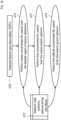
- the means for transmitting beacon signals from network nodes to network users can include geographically distributed network nodes at calibrated locations, which can be communicatively coupled to a means for central processing.
- the means for transmitting beacon signals may include an RDPN or an RDTN.
- Exemplary network nodes include fixed outdoor transmitters co-located with cellular transmission towers or 802.11 access points; indoor transmitters coexisting with 802.11 WLAN or 802.15 Bluetooth or Zigbee networks; or standalone transmitters.
- the means for central processing can include a NOC, e.g., a 5GNR MEC or a USS, which provisions each of the network nodes with configuration data or time symbols over a means for communicating data between the network nodes and the means for central processing.
- the means for communicating data can include an Ethernet-based network, a PLC network, an 802.11 WLAN, an 802.15 Zigbee or Bluetooth network, and/or a 3G, 4G LTE, or 5G cellular network.
- the means for transmitting beacon signals can include computer processors and computer-readable memory that programs the processors to generate and/or transmit the beacon signals.
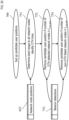
- the means for transmitting beacon signals from the network users to the network nodes can comprise a wireless communications apparatus onboard a user device configured to receive navigation signals or beacon configuration information from the means for central processing over an ancillary wireless communication link, and transmit beacon signals in the FoV of network nodes configured to receive the beacon signals.
- the means for transmitting beacon signals can comprise means for generating the beacons signals.
- the means for transmitting beacon signals can include computer processors and computer-readable memory that programs the processors to generate and/or transmit the beacon signals.
- the means for transponding beacon signals can comprise wireless communication transceivers that receive, condition, and retransmit the beacon signals without otherwise processing them.
- Network receivers e.g., network nodes
- the means for central processing can capture and backhaul snapshots of those retransmitted to the means for central processing, which can compute a P/T solution from the snapshots, and transmit the solution to the users over the ancillary wireless communication link.
- the means for transponding beacon signals can further comprise a wireless receiver for the ancillary wireless communication link.
- the means for transponding beacon signals can include computer processors and computer-readable memory that programs the processors to receive and transmit the beacon signals, and optionally, to receive the P/T solution.
- the means for transponding beacon signals may comprise an RDXN.
- the means for inducing can include a modulator configured to perform subcarrier spreading modulation, such as SCSS modulation.
- SCSS modulation subcarrier spreading modulation
- an inner code is replicated over multiple clusters, each of which is modulated by one element of an outer code.
- Spectral redundancy can be achieved by spreading a narrowband signal with a wideband signal.
- the means for inducing can include a modulator configured to repeat a time symbol. Time symbols may be organized in slots, with multiple repetitions per slot.
- the means for inducing may include a computer processor and computer-readable memory that programs the processor to perform the spreading and/or repetition of symbols.
- a software-defined radio is one example of such a processor.
- the means for inducing may comprise a multitone modulator, which can employ a DFT, IDFT, FFT, IFFT, polyphase filter, and/or a discrete filter bank.
- the means for exploiting can comprise any apparatus or computer program product having instructions that implement a resilient detection operation for excising CCI in a snapshot.
- the means for exploiting can comprise a subcarrier demodulator that eliminates inter-symbol interference and inter-subcarrier interference.
- the means for exploiting can perform code nulling or Class-C linear minimum-mean-square error (LMMSE) operations to separate co-channel received beacon signals with quality limited only by the received SNR of those signals, rather than the received SIR of those signals.
- LMMSE Class-C linear minimum-mean-square error
- the means for exploiting can further include spatial/polarization diverse antenna arrays at their transmitters or receivers, which allow for copy-aided DF methods to determine the DOA of the beacon signals, and copy-enhanced DF methods to determine the DOA of jammers.
- the means for exploiting may further comprise a means for channelizing.
- the means for channelizing can comprise a DFT, such as a sparse DFT, a windowed DFT, or a combination thereof. Equivalent structure, such as filters configured for snapshot channelization, may be used.
- the means for channelizing can comprise any apparatus or computer program product having instructions that channelize a snapshot. In one aspect, the means for channelizing removes an estimated coarse (cold-start) or fine (warm/hot start) observed LO offset, and removes timing offset, if necessary.
- the means for channelizing may separate the snapshot into frequency subcarriers and time symbols using a windowed DFT.
- a ninth aspect relates to an apparatus, comprising a means for generating a snapshot of a received plurality of beacon transmissions, each of the plurality of beacon transmissions having at least one of spectral redundancy and temporal redundancy; and means for exploiting the at least one of spectral redundancy and temporal redundancy to separate multiples ones of the beacon transmissions in the snapshot.
- the means for generating the snapshot can comprise any apparatus or computer program product having instructions that, when directed to, collects a snapshot, e.g., based on prompts from the means for central processing, or at scheduled snapshot collection times.
- the means for generating can include a receiver front-end configured to receive beacon signals, a frequency down-converter, and an ADC, as well as other radio components.
- the means for generating may comprise an SDR.
- a tenth aspect relates to an apparatus, comprising a means for receiving a snapshot of a received plurality of beacon transmissions, each of the plurality of beacon transmissions having at least one of spectral redundancy and temporal redundancy; and means for exploiting the at least one of spectral redundancy and temporal redundancy to separate multiples ones of the beacon transmissions in the snapshot.
- the means for receiving the plurality of beacon transmissions can comprise a receiver front-end of a radio configured to receive transmitted beacon signals.
- the means for receiving can include a frequency down-converter and an ADC, as well as other radio components.
- the means for receiving comprises an SDR.
- the means for receiving may comprise a network user's beacon receiver configured to receive beacon transmissions, such as beacon signals transmitted from network nodes.
- the means for receiving may comprise network nodes configured to receive beacon transmissions from network users.
- the means for receiving may comprise network nodes in an RDRN and/or network users in an RDTN or an RDXN.
- a thirteenth aspect relates to an apparatus, comprising a means for receiving multiple multitone beacon signals; and a means for exploiting spectral redundancy in the multiple multitone beacon signals to use code nulling or Class-C linear minimum-mean-square error methods to separate the multiple multitone beacon signals.
- the means for receiving multiple multitone beacon signals can include a multitone demodulator, which can employ a DFT, IDFT, FFT, IFFT, polyphase filter, and/or a discrete filter bank.
- the means for receiving may include at least one processor and at least one memory in electronic communication with the at least one processor, and instructions stored in the at least one memory to perform multitone demodulation.
- a software-defined radio is one example of such a processor.
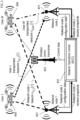
- the users 400 are in the FoV of 32 fixed network nodes 401, deployed at 15.2-to-45.7 (50-150 foot) elevations AGL, i.e., with a ground horizon of 27.9 km (17.3 miles) at maximum altitude, and in a roughly hexagonal layout, consistent with sparse deployment from cell towers, over a 17,227 square-kilometer area.
- FIG. 4B the users 400 are in the FoV of 50 fixed network nodes 401, deployed over the same range of altitudes, and over a 16,480 square-kilometer area.
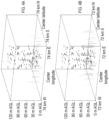
- the ADC output SINR ranges between -46 dB and +25 dB in the LMS Scenario, and between -39 dB and +8 dB in the 2.4 GHz Ch. 13 Scenario.
- the links are above 0 dB SNR in the LMS Scenario, only 3.5% of the links are above a 0 dB SINR, and less than 18% of the links are above a -10 dB SINR.
- 82% of the links are above 0 dB SNR in the 2.4 GHz Ch. 13 Scenario, but only 1.2% of the links are above 0 dB SINR, and 10% of the links are above a -10 dB SINR.
- the received beacons are clearly in an interference-limited environment. This is the reason that competing systems introduce time hopping and time slotting into their beacon transmitters - in order to avoid such interference.
- non-uniform amplitude weightings to either or both vectors, for example, to further reduce PAPR of the transmitted beacon, reduce interference to non-beacon networks caused by beacons in selected portions of the beacon transmission band, or reduce susceptibility to non-beacon interference at network receivers operating in the beacon transmission band.
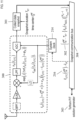
- the inner subcarrier vector 104 and outer subcarrier vector 106 are then combined 107 to form K sub ⁇ 1 full subcarrier vector 108
- this may be a more complex combining operation, for example, to improve robustness to LO frequency uncertainty at the transmitter or receiver, reduce interference to non-beacon networks caused by beacons in selected portions of the beacon transmission band, or reduce susceptibility to non-beacon interference at network receivers operating in the beacon transmission band.
- the preemphasis vector 110 can be designed using analytic models for beacon transmission operations 213; or using calibration data obtained at each network node 401, for example, as described in G.
- Pattabiraman S. Melyappan, A. Raghupathy, H. Sankar, "Wide Area Positioning System,” US Patent No. 8,130,141, issued March 2012 , and can be based on the magnitude or complex value of those beacon transmission operations 213.
- the multitone modulator 111 can be implemented using combinations of discrete Fourier transform (DFT), inverse DFT (IDFT), fast Fourier transform (FFT), or inverse FFT (IFFT) operations, or using polyphase filtering or discrete filter bank operations.
- Each time symbol vector 113 is then passed from the NOC 403 to the beacon transmitter over a beacon communication bus 114.
- Exemplary communication networks supporting a beacon communication bus 114 can include Ethernet-based networks, optical networks, power-line communication (PLC) networks, 802.11 WLAN's, 802.15 Zigbee or Bluetooth networks, or 3G, 4G LTE, or 5G cellular networks.
- PLC power-line communication
- the beacon communication bus 114 connects the NOC 403 to the network nodes 401.
- the beacon communication bus 114 connects the NOC 403 to the users 400 over a wireless communication transceiver 402.
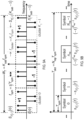
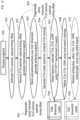
- FIG. 8 shows operations performed in this aspect of the disclosure at each beacon transmitter, e.g., the network nodes 401 for the networks shown in FIG. 1 and FIG. 3 , or the users 400 for the network shown in FIG. 2 .
- the N DAC ⁇ 1 time symbol vector 113 is first obtained from the beacon communication bus 114. If K sub is even, the time symbol vector 113 is placed through time symbol extension operation 211 to convert the N DAC ⁇ 1 time symbol vector 113 to a 2 N DAC ⁇ 1 time symbol vector 113 given by s ⁇ T l ⁇ s ⁇ T l ⁇ s ⁇ T l , and placed in local storage 212.
- the time symbol vector 113 in local storage 212 is then continuously and repeatedly cycled through beacon transmission operations 213, until a new time symbol is provided by the NOC 403, or it must cease transmission for other reasons, e.g., to comply with license provisions of spectra reserved for time-division-duplex (TDD) operation, or based on other instructions received from the NOC 403.
- TDD time-division-duplex
- the time symbol vector 113 is transmitted from the user 400 over varying time interval durations, dependent for example upon the priority of positioning/timing solutions demanded by the user 400 or the NOC 403, or user 400 energy conservation needs.
- the operations used to perform the beacon transmission operations 213 are analogous to an arbitrary waveform generator (AWG).
- AMG arbitrary waveform generator
- the operations comprise dual DAC, dual LPF, frequency shift operations using in-phase and quadrature LO's, and power amplification (PA) operations.
- PA power amplification
- many other means can be used to implement the beacon transmission operations 213, e.g., superheterodyne transmitters that convert the time symbol vector 113 to a real intermediate-frequency (real-IF) form and perform the frequency conversion in multiple steps, and polar modulators, for example, D. Kirkpatrick, E. McCune, Jr, "Polar Modulation Using Product Mode," US Patent No.
- the DAC and LO employed in the beacon transmission operations 213 are locked to a system clock 214, which in general, has a clock rate and timing that is offset from a common time standard, e.g., UTC.
- UTC a common time standard
- the system clock 214 is synchronized to an external time and frequency standard using an external source, e.g., a GNSS receiver (Rx) 215.
- the system clock 214 is brought into a common time standard using network calibration methods computed at the NOC 403, e.g., by providing the system clock 214 with clock synchronization data 215, e.g., timing and rate offset estimates ⁇ T (l) and ⁇ T (l) .
- the system clock 214 employed each user 400 can similarly be brought into synchronization with a common time standard using clock synchronization data 215 provided by the NOC 403.
- the network nodes 401 are provisioned with the code library 101, and the NOC 403 sends it the code indices 101 to be used to generate time symbol vector 113.
- each network node 401 can select its own code indices 101 and communicate it back to the NOC 403.
- FIG. 9 illustrates an exemplary subcarrier frequency layout assumed here, and illustrates the spectral redundancy imposed in aspects where a Kronecker product operation is used to construct the full subcarrier vector 108 from simple BPSK inner subcarrier vectors 102 and BPSK outer subcarrier vectors 103 ( FIG. 9A ); and illustrates the temporal structure of the beacon for an aspect in which the time symbols are organized into slots with N rep per slot ( FIG. 9B ).
- the inner subcarrier vector 103 is a 5-element vector [+1 +1 -1 -1 +1] T
- the outer subcarrier vector 106 is a 4-element vector [+1 -1 -1 +1] T .
- FIG. 9B further illustrates the additional temporal redundancy in the beacon over each symbol repetition. If the time symbol possesses an even number of subcarriers, then the subcarriers will be offset from the frequency origin by a factor of f sym /2, similar to LTE SC-FDMA uplink signals. In this case, successive time symbol repetitions needed to be inverted to preserve signal energy within each subcarrier. If the time symbol possesses an odd number of subcarriers, then this offset is removed, similar to LTE OFDM downlink signals, and this successive inversion is not needed. The replication induces temporal redundancy in either case.
- Table 1 lists exemplary beacon generation and transmission parameters compatible with TOA and FOA ranges expected for Class-1 sUAS's, and for network geometries shown in FIG. 4 .
- the key parameter providing compatibility with Class-1 sUAS's is the 250 ⁇ s symbol duration T sym , which encompasses the full range of TOA's shown in FIG. 5 , driven by the maximum altitude allowed for Class-1 sUAS's.
- the resultant 4 kHz subcarrier frequency separation is also compatible with the range of FOA's shown in FIG. 5 , driven by the maximum airspeed allowed for Class-1 sUAS's. In each case, the beacon bandwidth fits into the channel allocation for each band.
- the 80-element inner subcarrier vector 104 dimension chosen for the 2.4 GHz Ch. 13 Scenario allows up to 80 co-channel beacons to be separated using linear-algebraic signal separation methods.
- the narrower bandwidth and sparser deployment degrades the geolocation capability of this network. However, the higher transmit power requirement compensates for much of this performance loss.
- a single time symbol vector 113 requires transmission of 2,880 bytes (2.8125 KB) over the beacon communication bus 114 for the LMS Scenario, and 28.125 KB for the 2.4 GHz Ch. 13 Scenario.
- the NOC 403 requires the beacon communication bus 114 to support a 23.04 kbps link for the LMS scenario, and a 230.4 kbps link for the 2.4 GHz Ch. 13 Scenario.
- the beacon is generated using inner subcarrier vector 104 and outer subcarrier vector 106 code phases with uniform-random phase distribution.
- This beacon has a PAPR of 11.2 dB, consistent with a bandlimited complex-Gaussian waveform.
- the other beacon is generated using 80-element inner subcarrier vector 104 and 60-element outer subcarrier vector 106 code phases taken from 1,000-member code libraries 102, in which the phases are optimized to minimize kurtosis of their underlying time series.
- This beacon has a PAPR of 3.15 dB.
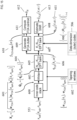
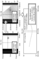
- FIG. 11 shows a receiver system used in one aspect of the disclosure.
- the receiver system When directed to collect a snapshot, e.g., based on prompts from the NOC 403 over a wireless communication transceiver 402, or at scheduled snapshot collection times, the receiver system performs reception operations 300 to generate a downconverted and sampled data stream covering the beacon transmission band.
- reception operations 300 can be implemented in many other ways, including two-stage superheterodyne reception operations 300 that downconvert the beacon transmission band to real-IF representation, and hybrid analog-digital reception operations 300 that downconvert a larger frequency band containing the beacon transmission band, and implements a digital drop receiver to generate a reduced-bandwidth, decimated signal centered on the beacon transmission band.
- the receiver system When needed at scheduled intervals, or given prompts from the NOC 403 over a wireless communication transceiver 402, the receiver system then performs a data snapshot collection 301 operation, which generates a snapshot 302 comprising the data provided by the reception operations 300 at a reception time and over a snapshot 302 time duration, shown in FIG. 11 as time center t R ref , and time duration T R also included as a time-stamp with that snapshot 302.
- a prefix and suffix with duration T prefix and T suffix are also collected as part of the snapshot 302, in order to encompass inter-slot interference introduced by timing offset between the beacon transmitter and receiver.
- the snapshot 302 is then sent to a position/timing (P/T) solution generator 303 over a snapshot communication bus 304.
- the snapshot communication bus 304 can be connected to the NOC 403 over a wireless communication transceiver 402, or it can connect to a P/T solution generator 303 on-board the user 400.
- the snapshot communication bus 304 is connected to the NOC 403 over a link similar to links supporting the beacon communication bus 114.
- the snapshot communication bus 304 typically requires a higher-rate link than the beacon communication bus 114.
- the NOC 403 also provides synchronization data 216 that can be used to bring the receiver system clock 214 into synchronization for subsequent time-stamped snapshots 302.
- the receiver obtains coarse synchronization information from the NOC 403 over a wireless communication transceiver 402.
- the receiver performs coarse synchronization operations to determine the approximate center frequency and (for slotted beacon formats) slot transition time of the beacons, prior to the snapshot collection 301. The coarse frequency and timing information can then be used to adjust the timing carrier offset of the ADC output signal, or the receiver clock driving the LO and ADC; or simply conveyed to the NOC 403, along with time-stamped snapshot 302.
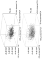
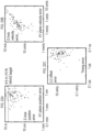
- the whitened snapshot matrix 604 is then passed through an FFT/IFFT mechanized resilient least-square (LS) search operation 507 to form a least-squares (LS) TOA-FOA surface 613, described in FIG. 15 , which provides a detection statistic as a function of candidate TOA and FOA values, and to search the LS TOA-FOA surface 613 to detect each beacon in the whitened snapshot matrix 604, using known data dimension codes 506 applied during beacon time-symbol generation operations shown in FIG. 7 , and to determine the observed TOA and FOA, and LS SINR (estimation quality) of the detected beacons.
- LS least-squares
- the maximizing TOA and FOA, and the maximal LS SINR are then refined 508, for example, using polynomial fit to the surface peak or parametric search operations in the vicinity of the detected TOA-FOA surface peak.
- a copy-aided parametric estimation method 510 is used to further refine TOA and FOA geo-observables and resolve detector ambiguities 510, using known DoF dimension codes 506 applied during beacon generation operations.
- results of the copy-aided parametric estimation method 510 is used to further improve estimates of the FOA centroid 612, and optionally the estimate of the timing offset, and the channelized snapshot 553 is regenerated 505 using the improved FOA centroid 612 and optional timing offset estimates, to further improve the geo-observable estimates.
- data dimension N data K 0 N sym
- FIG. 13 depicts exemplary operations used to implement the FOA centroid 612 and optional timing estimate removal and channelization operations 502 in one aspect.
- the system first performs a FOA centroid and optional timing offset removal operation 550, to remove the estimated FOA centroid 612 ⁇ R and optional estimated timing offset n ⁇ R from the snapshot 303.
- the prefix and suffix are also discarded prior during the FOA centroid and optional timing offset removal operation 550.
- the DFT out-put bins corresponding to the active beacon subcarrier frequencies are then selected, and a snapshot equalizer operation 552 is applied to those bins.
- the aggregate frequency response term is optional, and can be based on modeling of the reception operations 300; or derived from calibration operations performed by the receiver or network, for example, as described in Pattabiraman 2012, and can be based on the magnitude or complex value of those reception operations 300.
- Table 2 lists receiver and channelizer parameters compatible with the beacon generation and transmission parameters shown in Table 1.
- the receiver assumes a dual-ADC sampling rate of 3.84 million samples per second (Msps) for the LMS Scenario, and 30.72 Msps for the 2.4 GHz Ch. 13 Scenario, with sufficient antialiasing filtering to provide a 2 MHz and 20 MHz protected two-way passband, respectively, covering the active bandwidth of the beacons with ⁇ 40 kHz and ⁇ 400 kHz of guard band for LO uncertainty, respectively.
- a mixed-radix DFT with factor-of-four sparsity ( Q sym 4) is assumed in both scenarios, and a separation of 250 ⁇ s between successive DFT's.
- each snapshot is 112.5 KB for the LMS Scenario, and 900 KB for the 2.4 GHz Ch. 13 Scenario.
- backhaul 303 of ADC output data to the P/T solution generator requires a snapshot communication bus 304 that can support a 0.922 Mbps one-way data-rate for the LMS Scenario, and a 7.37 Mbps one-way data-rate for the 2.4 GHz Ch. 13 Scenario, well within capabilities of 4G cellular or 802.11 WLAN standards if the P/T solution generator 303 is in the NOC 403.
- the FOA centroid 612 and optional timing estimate removal and channelization operations 502 can be performed in a number of different manners, for example, using polyphase filtering methods, discrete filter banks centered on each subcarrier frequency, mixtures of radix-2 and non-radix-2 fast Fourier transform (FFT) and inverse-FFT methods, and so on.
- FFT fast Fourier transform
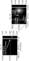
- FIG. 14 shows the frequency response of an exemplary DFT window developed for the LMS Scenario using an interpolated Parks-McClellan algorithm.
- the window passband is set to 1 kHz, corresponding ⁇ 136 Hz FOA offset expected in this band at the maximum class-1 sUAS airspeed of 44.7 meters/second (100 miles/hour), with ⁇ 864 Hz carrier offset margin after FOA centroid 612 removal operations.
- the window stopband is set to 3 kHz, sufficient to reject any inter-subcarrier interference due to FOA offset from the receiver center frequency.
- the window provides 3.7 dB rejection within its design passband (much less within ⁇ 136 Hz), and over 58 dB of rejection within its design stopband.
- the DFT window designed for the 2.4 GHz Ch. 13 Scenario has nearly identical performance.
- the background interference i sub ( k sub , n sym ) has identical power R i sub i sub ⁇ f ADC N 0 w R m ADC 2 2 on each channelizer output subcarrier
- beacon l has identical SNR ⁇ T (l) R ⁇
- the second dispersive term in (Eq20) can be ignored, and this correlation can be efficiently mechanized using DFT and inverse-DFT (IDFT) methods.
- FIG. 15 depicts one aspect employing resilient TOA-FOA estimation, referred to here as the fine least-squares procedure.
- ACM autocorrelation matrix
- LS least-squares
- the method sacrifices one despreader DoF to null each strong signal in the environment, and uses the despreader's remaining DoF's to improve the output SNR of the intended signal. It also admits superresolution geo-observable estimators with accuracy that scales with this output SINR.
- QRD can be implemented using a number of efficient methods known to those of ordinary skill in the arts, e.g., modified Gram-Schmidt orthogonalization (MGSO).
- MGSO modified Gram-Schmidt orthogonalization
- Other whitening operations e.g., singular value decomposition, can also be used to whiten X 0 .
- the clutter statistic is also used to improve the FOA centroid 612, e.g., using formula ⁇ ⁇ R ⁇ ⁇ ⁇ R + ⁇ ⁇ ⁇ ⁇ ⁇ FLS ⁇ clutter ⁇ ⁇ ⁇ ⁇ FLS ⁇ clutter ⁇ , which can be used to regenerate the channelized snapshot 553.
Landscapes
- Engineering & Computer Science (AREA)
- Physics & Mathematics (AREA)
- General Physics & Mathematics (AREA)
- Radar, Positioning & Navigation (AREA)
- Remote Sensing (AREA)
- Computer Networks & Wireless Communication (AREA)
- Mobile Radio Communication Systems (AREA)
- Radio Relay Systems (AREA)
- Position Fixing By Use Of Radio Waves (AREA)
Claims (14)
- Méthode comprenantsynthétiser des signaux de balise multitons, dans lesquels au moins l'un des éléments suivants est sélectionné : l'espacement des sous-porteuses en fonction d'une plage attendue de fréquence d'arrivée pour les utilisateurs du réseau ou la durée des symboles en fonction d'une plage attendue de temps d'arrivée pour les utilisateurs du réseau ;induire au moins l'une des redondances spectrales ou temporelles sur les signaux de balise multitons ; ettransmettre les signaux de balise multitoniques.
- La méthode de la revendication 1, dans laquelle la transmission comprend :transmettre les signaux de balise multitoniques des nœuds de réseau aux utilisateurs du réseau ; transmettre les signaux de balise multitoniques des utilisateurs du réseau aux nœuds de réseau ; outransmettre les signaux de balise multitonalité à destination et en provenance des nœuds du réseau par l'intermédiaire des utilisateurs du réseau.
- La méthode de la revendication 1, dans laquelle :les signaux de balise multitons comprennent des signaux de balise cocanal ; et l'induction comprend la modulation par étalement de sous-porteuse du canal communles signaux des balises.
- La méthode de la revendication 1, dans laquelle l'induction comprend la sélection déterministe, pseudo-aléatoire ou imprévisible d'un code interne et d'un code externe, la combinaison du code interne et du code externe pour produire un vecteur de sous-porteuse, et l'exécution d'une modulation multitonale sur le vecteur de sous-porteuse pour produire un signal dans le domaine temporel.
- La méthode de la revendication 4, dans laquelle le code interne et le code externe sont sélectionnés pour fournir au moins un vecteur de sous-porteuse avec un faible rapport puissance de crête/puissance moyenne ou un ensemble de vecteurs de sous-porteuse avec une faible corrélation croisée.
- La méthode de la revendication 4, dans laquelle le code interne et le code externe sont sélectionnés dans des bibliothèques de codes, et dans laquelle les phases de code sont optimisées pour minimiser l'aplatissement d'une série temporelle sous-jacente.
- La méthode de la revendication 1, dans laquelle l'induction est configurée pour produire une pluralité de degrés de liberté qui permet à un récepteur d'utiliser la séparation algébrique linéaire des signaux pour séparer une pluralité de signaux de balises multitons co-canal en une pluralité de signaux de balises multitons séparés dans un instantané des signaux reçus.
- Produit de programme informatique, caractérisé par : un support lisible par ordinateur comprenant : un code pour amener un ordinateur à mettre en œuvre la méthode de l'une des revendications 1 à 7.
- Appareil comprenantun générateur de symboles temporels configuré pour synthétiser des signaux de balise multitons, dans lequel au moins l'une des sous-porteuses est sélectionnée en fonction d'une plage attendue de fréquence d'arrivée pour les utilisateurs du réseau ou la durée des symboles est sélectionnée en fonction d'une plage attendue de temps d'arrivée pour les utilisateurs du réseau ; dans lequel le générateur de symboles temporels est configuré pour induire au moins l'une des redondances spectrales ou temporelles sur les signaux de balise multitons ; etun bus de communication de balise configuré pour coupler de manière communicative les signaux de balise multiton à au moins un émetteur de balise configuré pour transmettre les signaux de balise multiton aux utilisateurs du réseau.
- L'appareil de la revendication 9, dans lequel :les signaux de balise multitons comprennent des signaux de balise cocanal ; etl'induction consiste à effectuer une modulation par étalement de sous-porteuse des signaux de la balise co-canal.
- L'appareil de la revendication 9, dans lequel l'induction comprend la sélection déterministe, pseudo-aléatoire ou imprévisible d'un code interne et d'un code externe, la combinaison du code interne et du code externe pour produire un vecteur de sous-porteuse, et l'exécution d'une modulation multitonale sur le vecteur de sous-porteuse pour produire un signal dans le domaine temporel.
- L'appareil de la revendication 11, dans lequel le code interne et le code externe sont sélectionnés pour fournir au moins un vecteur de sous-porteuse avec un faible rapport puissance de crête/puissance moyenne ou un ensemble de vecteurs de sous-porteuse avec une faible corrélation croisée.
- L'appareil de la revendication 11, dans lequel le code interne et le code externe sont sélectionnés dans des bibliothèques de codes, dans lesquelles les phases de code sont optimisées pour minimiser l'aplatissement d'une série temporelle sous-jacente.
- L'appareil de la revendication 9, dans lequel l'induction est configurée pour produire une pluralité de degrés de liberté qui permet à un récepteur d'utiliser la séparation algébrique linéaire des signaux pour séparer une pluralité de signaux de balise multiton co-canal en une pluralité de signaux de balise multiton séparés dans un instantané des signaux reçus.
Priority Applications (1)
| Application Number | Priority Date | Filing Date | Title |
|---|---|---|---|
| EP25186514.3A EP4600686A3 (fr) | 2020-02-03 | 2021-02-03 | Réseaux de positionnement distribués résilients |
Applications Claiming Priority (3)
| Application Number | Priority Date | Filing Date | Title |
|---|---|---|---|
| US202062969264P | 2020-02-03 | 2020-02-03 | |
| US202163138300P | 2021-01-15 | 2021-01-15 | |
| PCT/US2021/016334 WO2021158609A2 (fr) | 2020-02-03 | 2021-02-03 | Réseaux de positionnement distribués élastiques |
Related Child Applications (1)
| Application Number | Title | Priority Date | Filing Date |
|---|---|---|---|
| EP25186514.3A Division EP4600686A3 (fr) | 2020-02-03 | 2021-02-03 | Réseaux de positionnement distribués résilients |
Publications (2)
| Publication Number | Publication Date |
|---|---|
| EP4100759A2 EP4100759A2 (fr) | 2022-12-14 |
| EP4100759B1 true EP4100759B1 (fr) | 2025-07-02 |
Family
ID=75426664
Family Applications (2)
| Application Number | Title | Priority Date | Filing Date |
|---|---|---|---|
| EP25186514.3A Pending EP4600686A3 (fr) | 2020-02-03 | 2021-02-03 | Réseaux de positionnement distribués résilients |
| EP21717254.3A Active EP4100759B1 (fr) | 2020-02-03 | 2021-02-03 | Réseaux de positionnement distribués élastiques |
Family Applications Before (1)
| Application Number | Title | Priority Date | Filing Date |
|---|---|---|---|
| EP25186514.3A Pending EP4600686A3 (fr) | 2020-02-03 | 2021-02-03 | Réseaux de positionnement distribués résilients |
Country Status (4)
| Country | Link |
|---|---|
| US (2) | US12386015B2 (fr) |
| EP (2) | EP4600686A3 (fr) |
| CN (1) | CN115053146A (fr) |
| WO (1) | WO2021158609A2 (fr) |
Families Citing this family (7)
| Publication number | Priority date | Publication date | Assignee | Title |
|---|---|---|---|---|
| WO2020068566A1 (fr) * | 2018-09-28 | 2020-04-02 | Sony Corporation | Procédé et appareil d'opération de bande passante adaptative |
| EP4115576A1 (fr) * | 2020-03-05 | 2023-01-11 | Red Bend Ltd. | Détection de détournement de communication sans fil |
| US11711254B2 (en) * | 2021-01-15 | 2023-07-25 | University Of Southern California | Sub-nanosecond RF synchronization for MIMO software defined radio sensor networks |
| US20250216202A1 (en) * | 2023-03-23 | 2025-07-03 | Navsys Corporation | Alternative systems and methods for global positioning, navigation, and timing |
| CN116359836B (zh) * | 2023-05-31 | 2023-08-15 | 成都金支点科技有限公司 | 一种基于超分辨率测向的无人机目标跟踪方法和系统 |
| CN119171938A (zh) * | 2023-06-20 | 2024-12-20 | 莱特普茵特公司 | 确定沿有线传输介质的信号传输中的延迟 |
| CN117908050B (zh) * | 2024-03-18 | 2024-06-18 | 成都航空职业技术学院 | 一种用于无人机导航的信标系统及导航方法 |
Family Cites Families (48)
| Publication number | Priority date | Publication date | Assignee | Title |
|---|---|---|---|---|
| US6108557A (en) | 1997-01-08 | 2000-08-22 | Us Wireless Corporation | Signature matching for location determination in wireless communication systems |
| US6026304A (en) | 1997-01-08 | 2000-02-15 | U.S. Wireless Corporation | Radio transmitter location finding for wireless communication network services and management |
| US6128276A (en) * | 1997-02-24 | 2000-10-03 | Radix Wireless, Inc. | Stacked-carrier discrete multiple tone communication technology and combinations with code nulling, interference cancellation, retrodirective communication and adaptive antenna arrays |
| US8233091B1 (en) | 2007-05-16 | 2012-07-31 | Trueposition, Inc. | Positioning and time transfer using television synchronization signals |
| US7511662B2 (en) * | 2006-04-28 | 2009-03-31 | Loctronix Corporation | System and method for positioning in configured environments |
| US20080151831A1 (en) * | 2006-12-22 | 2008-06-26 | Farooq Khan | Orthogonal repetition and hybrid ARQ scheme |
| US9213103B2 (en) | 2008-05-30 | 2015-12-15 | The Boeing Company | Cells obtaining timing and positioning by using satellite systems with high power signals for improved building penetration |
| CA2736768A1 (fr) | 2008-09-10 | 2010-03-18 | Commlabs, Inc. | Systeme de positionnement sur zone etendue |
| US9119165B2 (en) | 2009-09-10 | 2015-08-25 | Nextnav, Llc | Coding in a wide area positioning system (WAPS) |
| US9035829B2 (en) | 2008-09-10 | 2015-05-19 | Nextnav, Llc | Wide area positioning systems and methods |
| US9784815B2 (en) | 2011-06-28 | 2017-10-10 | Nextnav, Llc | Separating ranging and data signals in a wireless positioning system |
| US9645249B2 (en) | 2011-06-28 | 2017-05-09 | Nextnav, Llc | Systems and methods for pseudo-random coding |
| US9176217B2 (en) | 2011-08-02 | 2015-11-03 | Nextnav, Llc | Cell organization and transmission schemes in a wide area positioning system (WAPS) |
| US9360557B1 (en) | 2012-07-06 | 2016-06-07 | Apple Inc. | Systems, methods, devices and subassemblies for rapid-acquisition access to high-precision positioning, navigation and/or timing solutions |
| US10845453B2 (en) | 2012-08-03 | 2020-11-24 | Polte Corporation | Network architecture and methods for location services |
| US10863313B2 (en) | 2014-08-01 | 2020-12-08 | Polte Corporation | Network architecture and methods for location services |
| US9286490B2 (en) | 2013-09-10 | 2016-03-15 | Nextnav, Llc | Systems and methods for providing conditional access to transmitted information |
| US10812955B2 (en) | 2013-01-05 | 2020-10-20 | Brian G Agee | Generation of signals with unpredictable transmission properties for wireless M2M networks |
| US9648444B2 (en) | 2014-01-06 | 2017-05-09 | Brian G. Agee | Physically secure digital signal processing for wireless M2M networks |
| JP6639237B2 (ja) | 2013-03-07 | 2020-02-05 | テルコム・ベンチャーズ・エルエルシー | 方法、位置ネットワークセンタ、及び位置ネットワーク受信機 |
| WO2014151118A1 (fr) | 2013-03-15 | 2014-09-25 | Nextnav, Llc | Techniques pour améliorer les performances d'un réseau de positionnement radio fixe, à base temporelle au moyen d'informations d'assistance externe |
| US10598757B2 (en) | 2013-03-15 | 2020-03-24 | Nextnav, Llc | Systems and methods for improving the performance of a timing-based radio positioning network using estimated range biases |
| US20140266913A1 (en) | 2013-03-15 | 2014-09-18 | Nextnav, Llc | Performance enhancements for local network of beacons |
| CA2903453A1 (fr) | 2013-03-15 | 2014-09-25 | Nextnav, Llc | Systemes et procedes permettant d'utiliser des informations de localisation tridimensionnelles pour ameliorer des services de localisation |
| AU2014235359A1 (en) | 2013-03-15 | 2015-10-08 | Nextnav, Llc | Methods and systems for improving time of arrival determination |
| US10013860B2 (en) | 2014-01-16 | 2018-07-03 | Automaton, Inc. | Systems and methods for RFID-based retail management |
| US10042037B2 (en) | 2014-02-20 | 2018-08-07 | Nestwave Sas | System and method for estimating time of arrival (TOA) |
| US9720071B2 (en) | 2014-10-20 | 2017-08-01 | Nextnav, Llc | Mitigating effects of multipath during position computation |
| WO2016065314A1 (fr) | 2014-10-23 | 2016-04-28 | Automaton, Inc. | Systèmes et procédés de localisation d'étiquette d'identification par radiofréquence par interférence constructive |
| US10231201B2 (en) | 2014-12-08 | 2019-03-12 | Nextnav, Llc | Systems and methods for assured time synchronization of an RF beacon |
| KR20170094128A (ko) | 2014-12-08 | 2017-08-17 | 넥스트나브, 엘엘씨 | Rf 비콘에서 rf 신호를 선택적으로 수신 및 처리하기 위한 시스템 및 방법 |
| US9739872B2 (en) | 2015-01-21 | 2017-08-22 | Nextnav, Llc | Interference mitigation for positioning systems |
| US9913273B2 (en) | 2015-02-18 | 2018-03-06 | Nextnav, Llc | LTE-based wireless communication system for the M-LMS band |
| US10470184B2 (en) | 2015-02-18 | 2019-11-05 | Nextnav, Llc | LTE-based wireless communication system for the M-LMS band |
| EP3359979B1 (fr) | 2015-10-05 | 2020-12-09 | Nextnav, LLC | Systèmes et procédés pour générer des signaux à partir d'émetteurs terrestres, et pour traiter les signaux à l'aide de matériel de réception des systèmes globaux de navigation par satellite (gnss) |
| US10194269B2 (en) | 2015-10-12 | 2019-01-29 | Nextnav, Llc | Systems and methods for using doppler measurements to estimate a position of a receiver |
| US9397713B1 (en) | 2015-12-03 | 2016-07-19 | Eridan Communications, Inc. | Polar modulation using product mode |
| US9961559B2 (en) | 2015-12-14 | 2018-05-01 | Nestwave Sas | Accurate short range positioning with wireless signals |
| US9813877B1 (en) | 2015-12-14 | 2017-11-07 | Nestwave Sas | Accurate indoor positioning with cellular signals |
| US10281556B2 (en) | 2016-02-29 | 2019-05-07 | Nextnav, Llc | Interference detection and rejection for wide area positioning systems |
| US10194395B2 (en) | 2016-04-25 | 2019-01-29 | Nextnav, Llc | Systems and methods for low-power location determination using terrestrial signals |
| US10775510B2 (en) * | 2016-06-06 | 2020-09-15 | Brian G. Agee | Blind despreading of civil GNSS signals for resilient PNT applications |
| US10175945B2 (en) | 2016-06-17 | 2019-01-08 | Nextnav, Llc | Methods and systems for improving correlation |
| CN110691981B (zh) | 2017-03-28 | 2025-01-17 | 自动化公司 | 用于定位rfid标签的方法和设备 |
| US10880678B1 (en) | 2018-08-07 | 2020-12-29 | Nestwave Sas | Indoor and outdoor geolocation and time of arrival estimation |
| US20230236283A1 (en) | 2020-04-14 | 2023-07-27 | Pozyx N.V. | Improved Method and System for Positioning |
| CN116195311A (zh) * | 2020-09-18 | 2023-05-30 | 瑞典爱立信有限公司 | 初始化针对在无线网络中操作的空中用户设备(ue)的状态估计 |
| US12541002B2 (en) * | 2021-12-09 | 2026-02-03 | Nokia Technologies Oy | Positioning a terminal device |
-
2021
- 2021-02-03 EP EP25186514.3A patent/EP4600686A3/fr active Pending
- 2021-02-03 EP EP21717254.3A patent/EP4100759B1/fr active Active
- 2021-02-03 WO PCT/US2021/016334 patent/WO2021158609A2/fr not_active Ceased
- 2021-02-03 CN CN202180012689.8A patent/CN115053146A/zh active Pending
-
2022
- 2022-07-28 US US17/875,757 patent/US12386015B2/en active Active
-
2025
- 2025-08-06 US US19/292,839 patent/US20250362370A1/en active Pending
Also Published As
| Publication number | Publication date |
|---|---|
| EP4600686A3 (fr) | 2025-11-05 |
| EP4100759A2 (fr) | 2022-12-14 |
| US20220404454A1 (en) | 2022-12-22 |
| WO2021158609A3 (fr) | 2021-11-18 |
| US20250362370A1 (en) | 2025-11-27 |
| CN115053146A (zh) | 2022-09-13 |
| US12386015B2 (en) | 2025-08-12 |
| WO2021158609A2 (fr) | 2021-08-12 |
| EP4600686A2 (fr) | 2025-08-13 |
Similar Documents
| Publication | Publication Date | Title |
|---|---|---|
| EP4100759B1 (fr) | Réseaux de positionnement distribués élastiques | |
| US10983221B2 (en) | Adaptive despreading of civil beacons and GNSS signals using a channelized vector processing architecture | |
| US12228656B2 (en) | Resilient despreading of terrestrial navigation signals | |
| Nijsure et al. | Adaptive air-to-ground secure communication system based on ADS-B and wide-area multilateration | |
| Kozhaya et al. | Unveiling starlink for PNT | |
| US20160033649A1 (en) | Geolocation and frequency synchronization of earth-based satellite uplinks | |
| EP2957927B1 (fr) | Système et procédé permettant de déterminer l'emplacement d'une source de signal d'interférence | |
| JP6165430B2 (ja) | 衛星システムからの精確な絶対時刻の転送 | |
| CN108089205B (zh) | 一种无人机飞控人员定位系统 | |
| Kassas et al. | Assessment of cellular signals of opportunity for high-altitude aircraft navigation | |
| ES2899248T3 (es) | Receptor con filtro emparejado no coherente | |
| Herschfelt et al. | Joint positioning-communications system design and experimental demonstration | |
| Neinavaie et al. | Cognitive detection of unknown beacons of terrestrial signals of opportunity for localization | |
| Herschfelt | Simultaneous positioning and communications: Hybrid radio architecture, estimation techniques, and experimental validation | |
| US20180149728A1 (en) | Signal processing device and method, information processing device and method, and program | |
| Soualle et al. | New generation of PNT user terminals exploiting hybridization with LEO constellations | |
| Kassas et al. | I can hear you loud and clear: GNSS-less aircraft navigation with terrestrial cellular signals of opportunity | |
| Kassas et al. | The truth is out there: Cognitive sensing and opportunistic navigation with unknown terrestrial and nonterrestrial signals | |
| Domínguez et al. | Unified Navigation and Communication Hybrid Terminal | |
| Agee | Resilient Distributed Positioning Networks: A New Approach to Extreme Low-Latency, High-Precision Positioning and Timing | |
| Jallouli et al. | Initial positioning results with decoded iridium NEXT signals using a TDOA approach | |
| Sadowski | TDOA navigation using CDMA2000 signals—Experimental results | |
| Neinavaie | Cognitive sensing and navigation with unknown terrestrial and LEO satellite signals | |
| Dötterböck et al. | Retrieval of Encrypted PRN Sequences via a Selfcalibrating 40-element Low-cost Antenna Array: Demonstration of Proof-of-concept | |
| US7233777B2 (en) | Separation of AM cochannel signals in an overloaded signal environment |
Legal Events
| Date | Code | Title | Description |
|---|---|---|---|
| STAA | Information on the status of an ep patent application or granted ep patent |
Free format text: STATUS: UNKNOWN |
|
| STAA | Information on the status of an ep patent application or granted ep patent |
Free format text: STATUS: THE INTERNATIONAL PUBLICATION HAS BEEN MADE |
|
| PUAI | Public reference made under article 153(3) epc to a published international application that has entered the european phase |
Free format text: ORIGINAL CODE: 0009012 |
|
| STAA | Information on the status of an ep patent application or granted ep patent |
Free format text: STATUS: REQUEST FOR EXAMINATION WAS MADE |
|
| 17P | Request for examination filed |
Effective date: 20220905 |
|
| AK | Designated contracting states |
Kind code of ref document: A2 Designated state(s): AL AT BE BG CH CY CZ DE DK EE ES FI FR GB GR HR HU IE IS IT LI LT LU LV MC MK MT NL NO PL PT RO RS SE SI SK SM TR |
|
| DAV | Request for validation of the european patent (deleted) | ||
| DAX | Request for extension of the european patent (deleted) | ||
| REG | Reference to a national code |
Ref country code: DE Ref legal event code: R079 Free format text: PREVIOUS MAIN CLASS: G01S0005020000 Ipc: G01S0001040000 Ref country code: DE Ref legal event code: R079 Ref document number: 602021033305 Country of ref document: DE Free format text: PREVIOUS MAIN CLASS: G01S0005020000 Ipc: G01S0001040000 |
|
| GRAP | Despatch of communication of intention to grant a patent |
Free format text: ORIGINAL CODE: EPIDOSNIGR1 |
|
| STAA | Information on the status of an ep patent application or granted ep patent |
Free format text: STATUS: GRANT OF PATENT IS INTENDED |
|
| RIC1 | Information provided on ipc code assigned before grant |
Ipc: G01S 5/02 20100101ALI20250110BHEP Ipc: G01S 1/04 20060101AFI20250110BHEP |
|
| INTG | Intention to grant announced |
Effective date: 20250123 |
|
| GRAS | Grant fee paid |
Free format text: ORIGINAL CODE: EPIDOSNIGR3 |
|
| GRAA | (expected) grant |
Free format text: ORIGINAL CODE: 0009210 |
|
| STAA | Information on the status of an ep patent application or granted ep patent |
Free format text: STATUS: THE PATENT HAS BEEN GRANTED |
|
| AK | Designated contracting states |
Kind code of ref document: B1 Designated state(s): AL AT BE BG CH CY CZ DE DK EE ES FI FR GB GR HR HU IE IS IT LI LT LU LV MC MK MT NL NO PL PT RO RS SE SI SK SM TR |
|
| REG | Reference to a national code |
Ref country code: GB Ref legal event code: FG4D |
|
| REG | Reference to a national code |
Ref country code: CH Ref legal event code: EP |
|
| REG | Reference to a national code |
Ref country code: DE Ref legal event code: R096 Ref document number: 602021033305 Country of ref document: DE |
|
| REG | Reference to a national code |
Ref country code: IE Ref legal event code: FG4D |
|
| REG | Reference to a national code |
Ref country code: NL Ref legal event code: MP Effective date: 20250702 |
|
| PG25 | Lapsed in a contracting state [announced via postgrant information from national office to epo] |
Ref country code: PT Free format text: LAPSE BECAUSE OF FAILURE TO SUBMIT A TRANSLATION OF THE DESCRIPTION OR TO PAY THE FEE WITHIN THE PRESCRIBED TIME-LIMIT Effective date: 20251103 |
|
| PG25 | Lapsed in a contracting state [announced via postgrant information from national office to epo] |
Ref country code: NL Free format text: LAPSE BECAUSE OF FAILURE TO SUBMIT A TRANSLATION OF THE DESCRIPTION OR TO PAY THE FEE WITHIN THE PRESCRIBED TIME-LIMIT Effective date: 20250702 |
|
| REG | Reference to a national code |
Ref country code: AT Ref legal event code: MK05 Ref document number: 1809814 Country of ref document: AT Kind code of ref document: T Effective date: 20250702 |
|
| PG25 | Lapsed in a contracting state [announced via postgrant information from national office to epo] |
Ref country code: IS Free format text: LAPSE BECAUSE OF FAILURE TO SUBMIT A TRANSLATION OF THE DESCRIPTION OR TO PAY THE FEE WITHIN THE PRESCRIBED TIME-LIMIT Effective date: 20251102 |
|
| PG25 | Lapsed in a contracting state [announced via postgrant information from national office to epo] |
Ref country code: NO Free format text: LAPSE BECAUSE OF FAILURE TO SUBMIT A TRANSLATION OF THE DESCRIPTION OR TO PAY THE FEE WITHIN THE PRESCRIBED TIME-LIMIT Effective date: 20251002 |
|
| REG | Reference to a national code |
Ref country code: LT Ref legal event code: MG9D |
|
| PG25 | Lapsed in a contracting state [announced via postgrant information from national office to epo] |
Ref country code: AT Free format text: LAPSE BECAUSE OF FAILURE TO SUBMIT A TRANSLATION OF THE DESCRIPTION OR TO PAY THE FEE WITHIN THE PRESCRIBED TIME-LIMIT Effective date: 20250702 |
|
| PG25 | Lapsed in a contracting state [announced via postgrant information from national office to epo] |
Ref country code: FI Free format text: LAPSE BECAUSE OF FAILURE TO SUBMIT A TRANSLATION OF THE DESCRIPTION OR TO PAY THE FEE WITHIN THE PRESCRIBED TIME-LIMIT Effective date: 20250702 |
|
| PG25 | Lapsed in a contracting state [announced via postgrant information from national office to epo] |
Ref country code: HR Free format text: LAPSE BECAUSE OF FAILURE TO SUBMIT A TRANSLATION OF THE DESCRIPTION OR TO PAY THE FEE WITHIN THE PRESCRIBED TIME-LIMIT Effective date: 20250702 |
|
| PG25 | Lapsed in a contracting state [announced via postgrant information from national office to epo] |
Ref country code: GR Free format text: LAPSE BECAUSE OF FAILURE TO SUBMIT A TRANSLATION OF THE DESCRIPTION OR TO PAY THE FEE WITHIN THE PRESCRIBED TIME-LIMIT Effective date: 20251003 |
|
| PG25 | Lapsed in a contracting state [announced via postgrant information from national office to epo] |
Ref country code: SE Free format text: LAPSE BECAUSE OF FAILURE TO SUBMIT A TRANSLATION OF THE DESCRIPTION OR TO PAY THE FEE WITHIN THE PRESCRIBED TIME-LIMIT Effective date: 20250702 Ref country code: CZ Free format text: LAPSE BECAUSE OF FAILURE TO SUBMIT A TRANSLATION OF THE DESCRIPTION OR TO PAY THE FEE WITHIN THE PRESCRIBED TIME-LIMIT Effective date: 20250702 |
|
| PG25 | Lapsed in a contracting state [announced via postgrant information from national office to epo] |
Ref country code: LV Free format text: LAPSE BECAUSE OF FAILURE TO SUBMIT A TRANSLATION OF THE DESCRIPTION OR TO PAY THE FEE WITHIN THE PRESCRIBED TIME-LIMIT Effective date: 20250702 |
|
| PG25 | Lapsed in a contracting state [announced via postgrant information from national office to epo] |
Ref country code: BG Free format text: LAPSE BECAUSE OF FAILURE TO SUBMIT A TRANSLATION OF THE DESCRIPTION OR TO PAY THE FEE WITHIN THE PRESCRIBED TIME-LIMIT Effective date: 20250702 Ref country code: PL Free format text: LAPSE BECAUSE OF FAILURE TO SUBMIT A TRANSLATION OF THE DESCRIPTION OR TO PAY THE FEE WITHIN THE PRESCRIBED TIME-LIMIT Effective date: 20250702 |
|
| PG25 | Lapsed in a contracting state [announced via postgrant information from national office to epo] |
Ref country code: RS Free format text: LAPSE BECAUSE OF FAILURE TO SUBMIT A TRANSLATION OF THE DESCRIPTION OR TO PAY THE FEE WITHIN THE PRESCRIBED TIME-LIMIT Effective date: 20251002 |
|
| PG25 | Lapsed in a contracting state [announced via postgrant information from national office to epo] |
Ref country code: ES Free format text: LAPSE BECAUSE OF FAILURE TO SUBMIT A TRANSLATION OF THE DESCRIPTION OR TO PAY THE FEE WITHIN THE PRESCRIBED TIME-LIMIT Effective date: 20250702 |