EP4100670B1 - Ball valve assembly - Google Patents
Ball valve assembly Download PDFInfo
- Publication number
- EP4100670B1 EP4100670B1 EP21750235.0A EP21750235A EP4100670B1 EP 4100670 B1 EP4100670 B1 EP 4100670B1 EP 21750235 A EP21750235 A EP 21750235A EP 4100670 B1 EP4100670 B1 EP 4100670B1
- Authority
- EP
- European Patent Office
- Prior art keywords
- rotatable ring
- ball
- drive plate
- rotation
- valve assembly
- Prior art date
- Legal status (The legal status is an assumption and is not a legal conclusion. Google has not performed a legal analysis and makes no representation as to the accuracy of the status listed.)
- Active
Links
Images


Classifications
-
- F—MECHANICAL ENGINEERING; LIGHTING; HEATING; WEAPONS; BLASTING
- F16—ENGINEERING ELEMENTS AND UNITS; GENERAL MEASURES FOR PRODUCING AND MAINTAINING EFFECTIVE FUNCTIONING OF MACHINES OR INSTALLATIONS; THERMAL INSULATION IN GENERAL
- F16K—VALVES; TAPS; COCKS; ACTUATING-FLOATS; DEVICES FOR VENTING OR AERATING
- F16K5/00—Plug valves; Taps or cocks comprising only cut-off apparatus having at least one of the sealing faces shaped as a more or less complete surface of a solid of revolution, the opening and closing movement being predominantly rotary
- F16K5/08—Details
- F16K5/14—Special arrangements for separating the sealing faces or for pressing them together
- F16K5/20—Special arrangements for separating the sealing faces or for pressing them together for plugs with spherical surfaces
- F16K5/201—Special arrangements for separating the sealing faces or for pressing them together for plugs with spherical surfaces with the housing or parts of the housing mechanically pressing the seal against the plug
-
- F—MECHANICAL ENGINEERING; LIGHTING; HEATING; WEAPONS; BLASTING
- F16—ENGINEERING ELEMENTS AND UNITS; GENERAL MEASURES FOR PRODUCING AND MAINTAINING EFFECTIVE FUNCTIONING OF MACHINES OR INSTALLATIONS; THERMAL INSULATION IN GENERAL
- F16K—VALVES; TAPS; COCKS; ACTUATING-FLOATS; DEVICES FOR VENTING OR AERATING
- F16K27/00—Construction of housing; Use of materials therefor
- F16K27/06—Construction of housing; Use of materials therefor of taps or cocks
- F16K27/067—Construction of housing; Use of materials therefor of taps or cocks with spherical plugs
-
- F—MECHANICAL ENGINEERING; LIGHTING; HEATING; WEAPONS; BLASTING
- F16—ENGINEERING ELEMENTS AND UNITS; GENERAL MEASURES FOR PRODUCING AND MAINTAINING EFFECTIVE FUNCTIONING OF MACHINES OR INSTALLATIONS; THERMAL INSULATION IN GENERAL
- F16K—VALVES; TAPS; COCKS; ACTUATING-FLOATS; DEVICES FOR VENTING OR AERATING
- F16K5/00—Plug valves; Taps or cocks comprising only cut-off apparatus having at least one of the sealing faces shaped as a more or less complete surface of a solid of revolution, the opening and closing movement being predominantly rotary
- F16K5/06—Plug valves; Taps or cocks comprising only cut-off apparatus having at least one of the sealing faces shaped as a more or less complete surface of a solid of revolution, the opening and closing movement being predominantly rotary with plugs having spherical surfaces; Packings therefor
- F16K5/0605—Plug valves; Taps or cocks comprising only cut-off apparatus having at least one of the sealing faces shaped as a more or less complete surface of a solid of revolution, the opening and closing movement being predominantly rotary with plugs having spherical surfaces; Packings therefor with particular plug arrangements, e.g. particular shape or built-in means
-
- F—MECHANICAL ENGINEERING; LIGHTING; HEATING; WEAPONS; BLASTING
- F16—ENGINEERING ELEMENTS AND UNITS; GENERAL MEASURES FOR PRODUCING AND MAINTAINING EFFECTIVE FUNCTIONING OF MACHINES OR INSTALLATIONS; THERMAL INSULATION IN GENERAL
- F16K—VALVES; TAPS; COCKS; ACTUATING-FLOATS; DEVICES FOR VENTING OR AERATING
- F16K5/00—Plug valves; Taps or cocks comprising only cut-off apparatus having at least one of the sealing faces shaped as a more or less complete surface of a solid of revolution, the opening and closing movement being predominantly rotary
- F16K5/08—Details
- F16K5/14—Special arrangements for separating the sealing faces or for pressing them together
- F16K5/20—Special arrangements for separating the sealing faces or for pressing them together for plugs with spherical surfaces
- F16K5/204—Special arrangements for separating the sealing faces or for pressing them together for plugs with spherical surfaces with the plugs or parts of the plugs mechanically pressing the seals against the housing
-
- F—MECHANICAL ENGINEERING; LIGHTING; HEATING; WEAPONS; BLASTING
- F16—ENGINEERING ELEMENTS AND UNITS; GENERAL MEASURES FOR PRODUCING AND MAINTAINING EFFECTIVE FUNCTIONING OF MACHINES OR INSTALLATIONS; THERMAL INSULATION IN GENERAL
- F16K—VALVES; TAPS; COCKS; ACTUATING-FLOATS; DEVICES FOR VENTING OR AERATING
- F16K5/00—Plug valves; Taps or cocks comprising only cut-off apparatus having at least one of the sealing faces shaped as a more or less complete surface of a solid of revolution, the opening and closing movement being predominantly rotary
- F16K5/06—Plug valves; Taps or cocks comprising only cut-off apparatus having at least one of the sealing faces shaped as a more or less complete surface of a solid of revolution, the opening and closing movement being predominantly rotary with plugs having spherical surfaces; Packings therefor
- F16K5/0663—Packings
- F16K5/0689—Packings between housing and plug
Definitions
- Ball valve assemblies are used to control fluid flow through a well string.
- Ball valve assemblies include a ball having a fluid pathway extending through the ball.
- the ball valve assembly While the ball valve assembly is in an open state (e.g., open position of the ball), the fluid pathway of the ball is aligned with a fluid passage of the ball valve assembly, thereby enabling fluid to flow through the ball valve assembly.
- the fluid pathway of the ball is oriented generally perpendicularly to the fluid passage of the ball valve assembly, thereby blocking fluid flow through the ball valve assembly.
- fluid pressure is used to drive annular seats against the ball to substantially block fluid flow through the fluid passage while the ball is in the closed position and to substantially block fluid from flowing out of the fluid passage/fluid pathway interface while the ball is in the open position.
- annular seat may be positioned adjacent to each end of the ball.
- a ring e.g., driver, piston, etc.
- Fluid pressure within the fluid passage may drive the ring to compress the annular seat against the ball.
- US 5676347 A describes a valve mechanism for installation in a pipe line comprising a central body section with end sections connected thereto and forming therewith a valve stopper chamber, the end sections each having an associated annular extension projecting into the valve stopper chamber and having an external sealing surface and an internal fluid-flow passage extending outwardly therefrom.
- a valve stopper is provided in the chamber having a flow passage extending therethrough and sealing surfaces bounding the flow passage with a structure for moving the stopper to a valve open position substantially aligning the stopper flow passage with the extension flow passages, and to a valve closed position with the stopper sealing surfaces extending beyond the annular inner face of the extension.
- An annular gasket encircles each end section extension and a thrust structure is operable to compress the gaskets against the sealing surfaces of the extensions and stopper when the stopper is in valve open and valve closed positions.
- JP S47 26020 U describes a valve assembly wherein a drive platen is non-rotatably coupled to a valve ball and configured to rotate with the ball, comprising an engagement feature configured to engage an engagement feature of a rotatable ring to drive the rotatable ring to rotate in response to rotation of the drive plate.
- the ball valve assembly 10 includes a housing 19 (e.g., body) configured to house a ball.
- the housing 19 may be a solid forged block of material (e.g., steel), as illustrated, the housing may be cast from a suitable material (e.g., steel), or the housing may be formed by another suitable technique.
- the housing may be formed from a single piece of material, or the housing may be formed from multiple pieces of material coupled to one another.
- the ball of the ball valve assembly 10 has a fluid pathway extending through the ball.
- the ball is configured to rotate between an open position and a closed position.
- the fluid pathway is configured to align with a fluid passage of the ball valve assembly 10 while the ball is in the open position to enable fluid flow through the ball valve assembly 10.
- the fluid pathway is configured to be offset from the fluid passage while the ball is in the closed position to block fluid flow through the ball valve assembly 10.
- the ball valve assembly includes an annular seat configured to engage the ball.
- the ball valve assembly also includes a rotatable ring positioned on an opposite side of the annular seat from the ball, and the rotatable ring includes a first engagement feature (e.g., substantially flat surface).
- the ball valve assembly includes a non-rotatable ring positioned adjacent to the rotatable ring (e.g., on an opposite side of the rotatable ring from the annular seat).
- the ball valve also includes a drive plate non-rotatably coupled to the ball. Accordingly, the drive plate is configured to rotate with the ball between the open and closed positions.
- the drive plate includes a second engagement feature (e.g., substantially flat surface), and the second engagement feature of the drive plate is configured to engage the first engagement feature of the rotatable ring to drive the rotatable ring to rotate in response to rotation of the drive plate.
- the ball valve assembly includes bearing element(s) (e.g., spherical head pin(s), etc.) configured to drive the rotatable ring and the non-rotatable ring away from one another to compress the annular seat against the ball in response to rotation of the rotatable ring.
- bearing element(s) e.g., spherical head pin(s), etc.
- the drive plate which is non-rotatably coupled to the ball, rotates with the ball.
- the second engagement feature of the drive plate engages the first engagement feature of the rotatable ring.
- Rotation of the rotatable ring causes the bearing element(s) to drive the rotatable ring and the non-rotatable ring away from one another, thereby compressing the annular seat against the ball.
- the drive plate which is non-rotatably coupled to the ball, rotates with the ball.
- the second engagement feature of the drive plate engages the first engagement feature of the rotatable ring. Further rotation of the ball causes the drive plate to drive the rotatable ring to rotate via engagement of the first and second engagement features. Rotation of the rotatable ring causes the bearing element(s) to drive the rotatable ring and the non-rotatable ring away from one another, thereby compressing the annular seat against the ball.
- the annular seat is compressed against the ball by mechanical force applied by the drive plate, the rotatable ring, and the bearing element(s) (e.g., alone or in combination with a force applied by pressurized fluid within the ball valve assembly, as discussed in detail below).
- the annular seat may be compressed with significantly more force than an annular seat in a ball valve assembly that uses fluid pressure alone to compress the annular seat against the ball. Therefore, the ball valve assembly disclosed herein may be used for applications having operational conditions that are unsuitable for a ball valve assembly in which the annular seat is compressed against the ball by application of fluid pressure alone.
- FIG. 2 is a cross-sectional view of the ball valve assembly 10 of FIG. 1 , taken along line 2-2 of FIG. 1 .
- the housing 19 e.g., body
- the ball valve assembly 10 also includes an adapter 22 (e.g., bonnet) coupled to the housing 19.
- the adapter 22 is coupled to the housing 19 by fasteners 24, such as the illustrated bolts/nuts.
- the adapter 22 may be coupled to the housing 19 by any other suitable type of connection or combination of connections (e.g., alone or in combination with the fasteners 24).
- the ball valve assembly 10 includes a ball 26 disposed within the housing 19 and having a fluid pathway 28.
- the ball 26 is retained within an internal cavity 30 of the housing 19 by the adapter 22.
- the ball 26 is configured to rotate about a rotational axis 32 between an open position and a closed position.
- the fluid pathway 28 of the ball 26 is configured to align with the fluid passage 20 of the housing 19 while the ball 26 is in the open position to enable fluid flow through the fluid passage 20.
- the fluid pathway 28 of the ball 26 is configured to be offset from the fluid passage 20 of the housing 19 while the ball 26 is in the closed position to substantially block fluid flow through the fluid passage 20.
- a stem 34 extends through the adapter 22 and non-rotatably couples to the ball 26.
- the stem 34 may be driven to rotate by manual input and/or by an actuator, such as a hydraulic actuator, an electromechanical actuator, a pneumatic actuator, another suitable type of actuator, or a combination thereof.
- an actuator such as a hydraulic actuator, an electromechanical actuator, a pneumatic actuator, another suitable type of actuator, or a combination thereof.
- the ball valve assembly 10 includes a sealing system 36 configured to substantially block fluid flow through the fluid passage 20 while the ball 26 is in the closed position and to substantially block fluid from flowing out of the fluid passage 20/fluid pathway 28 interface while the ball 26 is in the open position.
- the sealing system 36 includes a first seat, such as the illustrated first annular seat 38, and a second seat, such as the illustrated second annular seat 40.
- Each annular seat is configured to engage the ball 26.
- each annular seat may be compressed against the ball (e.g., energized) while the ball is in the open position and/or while the ball is in the closed position.
- each annular seat is substantially aligned with the fluid passage 20 of the housing 19.
- each annular seat is substantially coaxial with the fluid passage 20 (e.g., the fluid passage 20 and each annular seat have a common longitudinal axis 42).
- Each annular seat may be formed from any suitable material or combination of materials, such as rubber, a polymeric material, metal, another suitable material, or a combination thereof.
- at least one annular seat may include an annular polymeric seal disposed within a metal seal retainer.
- the annular seat may include a lip seal (e.g., including a coil spring extending circumferentially about the annular seat).
- the sealing system 36 includes a first rotatable ring 44 and a second rotatable ring 46.
- the first rotatable ring 44 is positioned on an opposite side of the first annular seat 38 from the ball 26 along the longitudinal axis 42 of the fluid passage 20
- the second rotatable ring 46 is positioned on an opposite side of the second annular seat 40 from the ball 26 along the longitudinal axis 42 of the fluid passage 20.
- Each rotatable ring is configured to rotate about the longitudinal axis 42 of the fluid passage 20, and each rotatable ring includes one or more engagement features, as discussed in detail below.
- each rotatable ring is substantially aligned with the fluid passage 20 of the housing 19. Accordingly, each rotatable ring is substantially coaxial with the fluid passage 20 (e.g., the fluid passage 20 and each rotatable ring have a common longitudinal axis 42).
- the sealing system 36 includes a first non-rotatable ring 48 and a second non-rotatable ring 50.
- the first non-rotatable ring 48 is positioned adjacent to the first rotatable ring 44 on an opposite side of the first rotatable ring 44 from the first annular seat 38 along the longitudinal axis 42 of the fluid passage 20
- the second non-rotatable ring 50 is positioned adjacent to the second rotatable ring 46 on an opposite side of the second rotatable ring 46 from the second annular seat 40 along the longitudinal axis 42 of the fluid passage 20.
- rotation of each non-rotatable ring about the longitudinal axis 42 of the fluid passage 20 is blocked.
- each non-rotatable ring is substantially aligned with the fluid passage 20 of the housing 19. Accordingly, each non-rotatable ring is substantially coaxial with the fluid passage 20 (e.g., the fluid passage 20 and each non-rotatable ring have a common longitudinal axis 42).
- the sealing system 36 of the ball valve assembly 10 also includes a first drive plate 52 non-rotatably coupled to the ball 26 and a second drive plate 54 non-rotatably coupled to the ball 26.
- Each drive plate is configured to rotate with the ball.
- the ball may have polygonal protrusions
- each drive plate may have a corresponding polygonal recess configured to receive a respective polygonal protrusion of the ball. Engagement of each polygonal protrusion of the ball with the corresponding polygonal recess of the respective drive plate non-rotatably couples the respective drive plate to the ball.
- each drive plate includes one or more engagement features, and each engagement feature of the drive plate is configured to engage a corresponding engagement feature of a respective rotatable ring (e.g., as the ball approaches the open position and/or the closed position). While an engagement feature of a drive plate is engage with a corresponding engagement feature of a rotatable ring, rotation of the drive plate drives the rotatable ring to rotate.
- the sealing system 36 includes one or more first bearing elements and one or more second bearing elements.
- the first bearing element(s) are configured to drive the first rotatable ring 44 and the first non-rotatable ring 48 away from one another to compress (e.g., energize) the first annular seat 38 against the ball 26 in response to rotation of the first rotatable ring 44.
- the second bearing element(s) are configured to drive the second rotatable ring 46 and the second non-rotatable ring 50 away from one another to compress (e.g., energize) the second annular seat 40 against the ball 26 in response to rotation of the second rotatable ring 46.
- each annular seat is compressed against the ball by mechanical force applied by the drive plates, the rotatable rings, and the bearing elements (e.g., alone or in combination with a force applied by pressurized fluid within the ball valve assembly, as discussed in detail below).
- each annular seat may be compressed with significantly more force than an annular seat in a ball valve assembly that uses fluid pressure alone to compress the annular seat against the ball. Therefore, the ball valve assembly disclosed herein may be used for applications having operational conditions that are unsuitable for a ball valve assembly in which the annular seats are compressed against the ball by application of fluid pressure alone.
- FIG. 3 is a perspective view of the ball 26 and the sealing system 36 of the ball valve assembly 10 of FIG. 1 , in which the ball 26 is in the closed position.
- the ball 26 has a recess 56 configured to receive a corresponding protrusion of the stem.
- the recess 56 of the ball 26 and the protrusion of the stem are shaped to non-rotatably couple the stem to the ball 26 while the protrusion is engaged with the recess 56.
- the recess 56 is substantially rectangular.
- the recess may have any other suitable shape (e.g., elliptical, hexagonal, star-shaped, etc.).
- the stem and the ball may be non-rotatably coupled to one another by any other suitable connection (e.g., welded connection, pinned connection, integrally formed as one unit, etc.). Because the stem and the ball 26 are non-rotatably coupled to one another, rotation of the stem drives the ball 26 to rotate (e.g., between the illustrated closed position and the open position).
- any other suitable connection e.g., welded connection, pinned connection, integrally formed as one unit, etc.
- the ball 26 includes a first polygonal protrusion 55
- the first drive plate 52 includes a corresponding polygonal recess 57 (e.g., opening) configured to receive the first polygonal protrusion 55 of the ball 26.
- Engagement of the first polygonal protrusion 55 of the ball 26 with the corresponding polygonal recess 57 of the first drive plate 52 non-rotatably couples the first drive plate 52 to the ball 26.
- the first protrusion and the corresponding recess are polygonal in the illustrated embodiment, in other embodiments, the protrusion and the corresponding recess may have any other suitable shape (e.g., elliptical, star-shaped, etc.).
- the first drive plate may be non-rotatably coupled to the ball by another suitable connection (e.g., alone or in combination with the protrusion/recess connection), such as a fastener connection, a welded connection, an adhesive connection, other suitable connection(s), or a combination thereof.
- another suitable connection e.g., alone or in combination with the protrusion/recess connection
- a fastener connection e.g., a welded connection
- an adhesive connection e.g., an adhesive connection(s), or a combination thereof.
- the first drive plate may be non-rotatably coupled to the ball via another suitable structure, such as the stem.
- each anti-rotation plate 58 is coupled to the housing by one or more fasteners 64.
- At least one anti-rotation plate may be coupled to the housing by other suitable type(s) of connection(s) (e.g., alone or in combination with the fastener(s)), such as a welded connection, an adhesive connection, a press-fit connection, other suitable type(s) of connection(s), or a combination thereof.
- suitable type(s) of connection(s) e.g., alone or in combination with the fastener(s)
- connection(s) e.g., alone or in combination with the fastener(s)
- suitable type(s) of connection(s) e.g., alone or in combination with the fastener(s)
- a welded connection e.g., an adhesive connection, a press-fit connection, other suitable type(s) of connection(s), or a combination thereof.
- more or fewer anti-rotation plates e.g., 0, 1, 3, 4, or more
- the first rotatable ring 44 includes two engagement features (e.g., first engagement features), the second rotatable ring 46 includes two engagement features (e.g., second engagement features), the first drive plate 52 includes two engagement features (e.g., second engagement features, third engagement features), and the second drive plate 54 includes two engagement features (e.g., fourth engagement features).
- one engagement feature 66 of the first drive plate 52 is in contact with a corresponding engagement feature 68 of the first rotatable ring 44
- another engagement feature 70 of the first drive plate 52 is in contact with a corresponding engagement feature 72 of the second rotatable ring 46.
- rotation of the second rotatable ring 46 from a first position (e.g., in which the engagement features of the first drive plate and the second rotatable ring are not engaged with one another) to a second position (e.g., in which the second rotatable ring is rotated about the longitudinal axis) causes the respective bearing element(s) to drive the second rotatable ring 46 and the second non-rotatable ring 50 away from one another along the longitudinal axis 42, thereby compressing the second annular seat 40 against the ball 26.
- each annular seat is compressed against the ball by mechanical force applied by the first drive plate, the rotatable rings, and the bearing elements (e.g., alone or in combination with a force applied by pressurized fluid within the ball valve assembly, as discussed in detail below).
- each annular seat may be compressed with significantly more force than an annular seat in a ball valve assembly that uses fluid pressure alone to compress the annular seat against the ball. Therefore, the ball valve assembly disclosed herein may be used for applications having operational conditions that are unsuitable for a ball valve assembly in which the annular seats are compressed against the ball by application of fluid pressure alone.
- FIG. 4 is a bottom view of the ball 26 and the sealing system 36 of FIG. 3 , in which the ball 26 is in an open position.
- the ball 26 includes a second polygonal protrusion 75
- the second drive plate 54 includes a corresponding polygonal recess 77 (e.g., opening) configure to receive the second polygonal protrusion 75 of the ball 26.
- Engagement of the second polygonal protrusion 75 of the ball 26 with the corresponding polygonal recess 77 of the second drive plate 54 non-rotatably couples the second drive plate 54 to the ball 26.
- the second protrusion and the corresponding recess are polygonal in the illustrated embodiment, in other embodiments, the protrusion and the corresponding recess may have any other suitable shape (e.g., elliptical, star-shaped, etc.).
- the second drive plate may be non-rotatably coupled to the ball by another suitable connection (e.g., alone or in combination with the protrusion/recess connection), such as a fastener connection, a welded connection, an adhesive connection, other suitable connection(s), or a combination thereof.
- one engagement feature 76 of the second drive plate 54 is in contact with a corresponding engagement feature 78 of the first rotatable ring 44, and another engagement feature 80 of the second drive plate 54 is in contact with a corresponding engagement feature 82 of the second rotatable ring 46.
- the ball 26 may rotate in a second rotational direction 84 about the rotational axis from the closed position toward the illustrated open position.
- the engagement feature 76 of the second drive plate 54 engages the corresponding engagement feature 78 of the first rotatable ring 44
- the engagement feature 80 of the second drive plate 54 engages the corresponding engagement feature 82 of the second rotatable ring 46.
- Rotation of the first rotatable ring 44 from a first position (e.g., in which the engagement features of the second drive plate and the first rotatable ring are not engaged with one another) to a second position (e.g., in which the first rotatable ring is rotated about the longitudinal axis) causes the respective bearing element(s) to drive the first rotatable ring 44 and the first non-rotatable ring 48 away from one another along the longitudinal axis 42, thereby compressing the first annular seat 38 against the ball 26.
- rotation of the second rotatable ring 46 from a first position (e.g., in which the engagement features of the second drive plate and the second rotatable ring are not engaged with one another) to a second position (e.g., in which the second rotatable ring is rotated about the longitudinal axis) causes the respective bearing element(s) to drive the second rotatable ring 46 and the second non-rotatable ring 50 away from one another along the longitudinal axis 42, thereby compressing the second annular seat 40 against the ball 26.
- each annular seat is compressed against the ball by mechanical force applied by the second drive plate, the rotatable rings, and the bearing elements (e.g., alone or in combination with a force applied by pressurized fluid within the ball valve assembly, as discussed in detail below).
- each annular seat may be compressed with significantly more force than an annular seat in a ball valve assembly that uses fluid pressure alone to compress the annular seat against the ball. Therefore, the ball valve assembly disclosed herein may be used for applications having operational conditions that are unsuitable for a ball valve assembly in which the annular seats are compressed against the ball by application of fluid pressure alone.
- each engagement feature includes a substantially flat surface configured to engage the substantially flat surface of a corresponding engagement feature.
- the substantially flat surface of each engagement feature may be angled (e.g., about 1 degree to about 10 degrees, about 2 degrees to about 7 degrees, or about 5 degrees) relative to a radial axis of the respective ring/plate to facilitate engagement of the respective engagement features.
- at least one engagement feature may include another suitable surface and/or device (e.g., rounded surface, protrusion configured to engage a recess, etc.) configured to engage a corresponding engagement feature.
- non-rotatable rings are configured to move along the longitudinal axis in the illustrated embodiment, in other embodiments, movement of at least one non-rotatable ring along the longitudinal axis may be blocked.
- the bearing element(s) may drive the respective rotatable ring(s) away from the respective non-rotatable ring(s) along the longitudinal axis in response to rotation of the rotatable ring(s).
- each non-rotatable ring is positioned on an opposite side of the respective rotatable ring from the respective annular seat in the illustrated embodiment, in other embodiments, at least one non-rotatable ring may be positioned between the respective annular seat and the respective rotatable ring.
- the first drive plate 52 and the rotatable rings are configured such that the first drive plate 52 drives the rotatable rings to rotate as the ball 26 approaches the closed position
- the second drive plate 54 and the rotatable rings are configured such that the second drive plate 54 drives the rotatable rings to rotate as the ball 26 approaches the open position
- the first drive plate and the rotatable rings may be configured such that the first drive plate drives the rotatable rings to rotate as the ball approaches the open position
- the second drive plate and the rotatable rings may be configured such that the second drive plate drives the rotatable rings to rotate as the ball approaches the closed position.
- one of the drive plates may be omitted.
- the rotatable rings may only be driven to rotate as the ball approaches the closed position or the open position.
- the sealing system may include two driving plates that cooperate to drive the rotatable rings to rotate (e.g., as the ball approaches the closed position or the open position).
- the sealing system may include a single annular seat, rotatable ring, and non-rotatable ring. In such embodiments, only one annular seat may be compressed against the ball by mechanical force, and each driving plate may only include a single engagement feature.
- each spherical head pin 88 is coupled to the first non-rotatable ring 48 via an interference fit between the shaft 90 of the spherical head pin 88 and the corresponding recess 94.
- at least one spherical head pin may be coupled to the first non-rotatable ring by another suitable connection (e.g., a threaded connection, a welded connection, a pinned connection, an adhesive connection, a shrink-fit connection, etc.).
- the hemi-spherical head 92 of each spherical head pin 88 is configured to selectively engage a respective recess within the first rotatable ring 44. While the hemi-spherical heads 92 of the spherical head pins 88 are engaged with the respective recesses of the first rotatable ring 44, the first rotatable ring 44 and the first non-rotatable ring 48 may be positioned a minimum distance away from one another along the longitudinal axis 42 (e.g., touching one another, separated by a small gap, etc.).
- the hemi-spherical heads 92 of the spherical head pins 88 disengage the respective recesses of the first rotatable ring 44, thereby driving the first rotatable ring 44 and the first non-rotatable ring 48 away from one another along the longitudinal axis 42.
- "away from one another” refers to increasing the distance between the rotatable and non-rotatable rings and does not necessarily include movement of both rings (e.g., in embodiments in which movement of the non-rotatable ring along the longitudinal axis is blocked).
- each spherical head pin 88 is coupled to the first non-rotatable ring 48, and each respective recess is formed within the first rotatable ring 44.
- at least one spherical head pin may be coupled to the first rotatable ring, and at least one respective recess may be formed within the first non-rotatable ring.
- bearing elements 86 include spherical head pins 88 in the illustrated embodiment
- the bearing elements may include any other suitable type(s) of bearing element(s) (e.g., alone or in combination with the spherical head pin(s)), such as ball bearing(s) (e.g., captured by at least one of the rings), wedge(s) (e.g., formed on at least one of the rings), roller(s) (e.g., captured by at least one of the rings), other suitable type(s) of bearing element(s), or a combination thereof.
- ball bearing(s) e.g., captured by at least one of the rings
- wedge(s) e.g., formed on at least one of the rings
- roller(s) e.g., captured by at least one of the rings
- other suitable type(s) of bearing element(s) e.g., captured by at least one of the rings
- the sealing system 36 includes ten bearing elements 86 disposed circumferentially about the longitudinal axis 42 (e.g., flow path through the ball valve assembly).
- the sealing system may include more or fewer bearing elements (e.g., 1, 2, 4, 6, 8, 12, 14, 20, or more) arranged in any suitable configuration.
- first bearing element(s) configured to drive the first rotatable ring and the first non-rotatable ring away from one another are disclosed above, in certain embodiments, the sealing system may include second bearing element(s) configured to drive the second rotatable ring and the second non-rotatable ring away from one another.
- Such second bearing element(s) may include any of the features and/or variations disclosed herein with regard to the first bearing element(s).
- the first and second bearing elements may be the same as one another or different from one another.
- FIG. 6 is another exploded view of a portion of the sealing system 36 of FIG. 3 .
- recesses 96 are formed within the first rotatable ring 44.
- Each recess 96 is configured to receive a respective bearing element (e.g., spherical head pin).
- each recess 96 has a substantially conical shape (e.g., with straight walls, with curved walls, etc.).
- at least one recess may have another suitable shape (e.g., hemi-spherical, polygonal, etc.).
- the shape of each recess is configured to receive a respective bearing element while the bearing element is aligned with the recess.
- each recess wall 98 is configure to drive the rotatable and non-rotatable rings away from one another in response to movement that offsets the recess from the respective bearing element.
- each bearing element may disengage the respective recess 96 (e.g., while maintaining contact with the wall 98 of the recess 96).
- the bearing elements disengage the respective recesses 96, thereby separating the first rotatable ring 44 from the first non-rotatable ring 48, which compresses the first annular seat 38 against the ball.
- disengage refers to a bearing element that is not fully engaged with the respective recess.
- a disengaged bearing element includes a bearing element that is partially disengaged from the respective recess (e.g., in which the bearing element maintains contact with the wall of the recess) and a bearing element that is fully disengaged from the respective recess (e.g., in which the bearing element is in contact with the surface of the rotatable ring surrounding the recess).
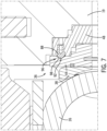
- FIG. 7 is a cross-sectional view of a portion of the sealing system 36 of FIG. 3 , in which a spherical head pin 88 is engaged with a respective recess 96. While the hemi-spherical head 92 of each spherical head pin 88 is engaged with a respective recess 96 of the first rotatable ring 44, the first rotatable ring 44 and the first non-rotatable ring 48 are positioned a minimum distance away from one another along the longitudinal axis (e.g., touching one another, separated by a small gap, etc.).
- the hemi-spherical head 92 of each spherical head pin 88 disengages the respective recess 96 of the first rotatable ring 44, thereby driving the first rotatable ring 44 and the first non-rotatable ring 48 away from one another along the longitudinal axis.
- FIG. 8 is a cross-sectional view of a portion of the sealing system 36 of FIG. 3 , in which the spherical head pin 88 is disengaged from the respective recess 96.
- each spherical head pin 88 disengages the respective recess 96.
- the spherical head pins 88 disengage the respective recesses 96, thereby driving the first rotatable ring 44 and the first non-rotatable ring 48 away from one another, which compresses the first annular seat 38 against the ball.
- each annular seat is compressed against the ball by mechanical force applied by the first/second drive plate, the rotatable ring(s), and the bearing element(s) (e.g., alone or in combination with a force applied by pressurized fluid within the ball valve assembly, as discussed in detail below).
- each annular seat may be compressed with significantly more force than an annular seat in a ball valve assembly that uses fluid pressure alone to compress the annular seat against the ball. Therefore, the ball valve assembly disclosed herein may be used for applications having operational conditions that are unsuitable for a ball valve assembly in which the annular seats are compressed against the ball by application of fluid pressure alone.
- the hemi-spherical head 92 of each spherical head pin 88 maintains contact with the wall 98 of the respective recess 96 while the first rotatable ring 44 is in the second position. Due to the shape of the wall 98 of each recess 96, the respective spherical head pin 88 may be urged into engagement with the recess 96 while the hemi-spherical head 92 of the spherical head pin 88 is in contact with the wall 98 of the recess 96.
- the bearing element(s) may contact the surface surrounding the recess(es) while the rotatable ring is in the second position, or the wall of each recess may be shaped to block re-engagement of the respective bearing element with the recess. In such embodiments, the bearing element(s) may remain disengaged from the respective recess(es) as the ball rotates away from the open/closed position and the engagement features disengaged one another.
- the ball valve assembly may utilize a combination of mechanical and hydraulic force to compress at least one annular seat against the ball.
- fluid within the fluid passage 20 may urge the first annular seat 38, the first rotatable ring 44, and the first non-rotatable ring 48 away from the ball via application of pressure to a first area 100 of the first annular seat 38.
- the first area 100 of the first annular seat 38 corresponds to the portion of the first annular seat 38 that faces the ball and is positioned radially inward from the portion of the first annular seat 38 that contacts the ball.
- the fluid within the fluid passage 20 may urge the first annular seat 38, the first rotatable ring 44, and the first non-rotatable ring 48 toward the ball via application of pressure to a second area 102 of the first non-rotatable ring 48.
- the second area 102 of the first non-rotatable ring 48 corresponds to the portion of the first non-rotatable ring 48 that faces away from the ball and is positioned radially inward from the portion of the first non-rotatable ring 48 that contacts the housing 19.
- the second area 102 is greater than the first area 100.
- a net force is applied to the first annular seat 38, the first rotatable ring 44, and the first non-rotatable ring 48 in a direction toward the ball, thereby further compressing the first annular seat 38 against the ball while the ball is in the open or closed position.
- the hydraulic force is disclosed above with regard to the first annular seat 38, the hydraulic force may be additionally or alternatively used to compress the second annular seat against the ball.
- the sealing system may include spring(s) (e.g., coil spring(s), leaf spring(s), etc.) configured to urge at least one annular seat/rotatable ring/non-rotatable ring toward the ball.
- spring(s) e.g., coil spring(s), leaf spring(s), etc.
- one or more springs may be positioned between the housing and at least one respective non-rotatable ring.
- the spring(s) enable movement of the annular seat(s), the rotatable ring(s), and the non-rotatable ring(s) to facilitate insertion of the ball during assembly of the ball valve assembly.
- the spring(s) urge the bearing element(s) into engagement with the respective recess(es).
- the force of the spring(s) may urge the hemi-spherical head of each spherical head pin to move along the wall of the respective recess until the spherical head pin is engaged (e.g., fully engaged) with the respective recess.
- the annular seat may be compressed with significantly more force than an annular seat in a ball valve assembly that uses fluid pressure alone to compress the annular seat against the ball. Therefore, the ball valve assembly disclosed herein may be used for applications having operational conditions that are unsuitable for a ball valve assembly in which the annular seat is compressed against the ball by application of fluid pressure alone.
Landscapes
- Engineering & Computer Science (AREA)
- General Engineering & Computer Science (AREA)
- Mechanical Engineering (AREA)
- Taps Or Cocks (AREA)
Description
- This section is intended to introduce the reader to various aspects of art that may be related to various aspects of the presently described embodiments. This discussion is believed to be helpful in providing the reader with background information to facilitate a better understanding of the various aspects of the present embodiments. Accordingly, it should be understood that these statements are to be read in this light, and not as admissions of prior art.
- In order to meet consumer and industrial demand for natural resources, companies search for and extract oil, natural gas, and other subterranean resources from the earth. Once a desired subterranean resource is discovered, drilling and production systems are employed to access and extract the resource. These systems may be located onshore or offshore depending on the location of a desired resource. For example, in subsea operations, hydrocarbon fluids such as oil and natural gas are obtained from a subterranean geologic formation, referred to as a reservoir, by drilling a well that penetrates the hydrocarbon-bearing geologic formation. In various subsea applications and other well applications, ball valve assemblies are used to control fluid flow through a well string. Ball valve assemblies include a ball having a fluid pathway extending through the ball. While the ball valve assembly is in an open state (e.g., open position of the ball), the fluid pathway of the ball is aligned with a fluid passage of the ball valve assembly, thereby enabling fluid to flow through the ball valve assembly. In addition, while the ball valve assembly is in a closed state (e.g., closed position of the ball), the fluid pathway of the ball is oriented generally perpendicularly to the fluid passage of the ball valve assembly, thereby blocking fluid flow through the ball valve assembly.
- In certain ball valve assemblies, fluid pressure is used to drive annular seats against the ball to substantially block fluid flow through the fluid passage while the ball is in the closed position and to substantially block fluid from flowing out of the fluid passage/fluid pathway interface while the ball is in the open position. For example, an annular seat may be positioned adjacent to each end of the ball. A ring (e.g., driver, piston, etc.) may be positioned adjacent to each annular seat on an opposite side of the annular seat from the ball. Fluid pressure within the fluid passage may drive the ring to compress the annular seat against the ball. Unfortunately, under operational conditions (e.g., fluid pressures, fluid flow rates, etc.) associated with certain applications, the fluid pressure may not provide a sufficient force to the rings to establish effective seals between the annular seats and the ball. Accordingly, a ball valve assembly, in which the annular seats are compressed against the ball by application of fluid pressure, may not be utilized for such applications.
-
US 5676347 A describes a valve mechanism for installation in a pipe line comprising a central body section with end sections connected thereto and forming therewith a valve stopper chamber, the end sections each having an associated annular extension projecting into the valve stopper chamber and having an external sealing surface and an internal fluid-flow passage extending outwardly therefrom. A valve stopper is provided in the chamber having a flow passage extending therethrough and sealing surfaces bounding the flow passage with a structure for moving the stopper to a valve open position substantially aligning the stopper flow passage with the extension flow passages, and to a valve closed position with the stopper sealing surfaces extending beyond the annular inner face of the extension. An annular gasket encircles each end section extension and a thrust structure is operable to compress the gaskets against the sealing surfaces of the extensions and stopper when the stopper is in valve open and valve closed positions. -
JP S47 26020 U - The present invention resides in a ball valve assembly as defined in claim 1. Preferred embodiments are defined in the appended claims.
- These and other features, aspects, and advantages of certain embodiments will become better understood when the following detailed description is read with reference to the accompanying drawings in which like characters represent like parts throughout the drawings, wherein:
-
FIG. 1 is a perspective view of an embodiment of a ball valve assembly; -
FIG. 2 is a cross-sectional view of the ball valve assembly ofFIG. 1 , taken along line 2-2 ofFIG. 1 ; -
FIG. 3 is a perspective view of a ball and a sealing system of the ball valve assembly ofFIG. 1 , in which the ball is in a closed position; -
FIG. 4 is a bottom view of the ball and the sealing system ofFIG. 3 , in which the ball is in an open position; -
FIG. 5 is an exploded view of a portion of the sealing system ofFIG. 3 ; -
FIG. 6 is another exploded view of a portion of the sealing system ofFIG. 3 ; -
FIG. 7 is a cross-sectional view of a portion of the sealing system ofFIG. 3 , in which a spherical head pin is engaged with a respective recess; and -
FIG. 8 is a cross-sectional view of a portion of the sealing system ofFIG. 3 , in which the spherical head pin is disengaged from the respective recess. - Specific embodiments of the present disclosure are described below. In an effort to provide a concise description of these embodiments, all features of an actual implementation may not be described in the specification. It should be appreciated that in the development of any such actual implementation, as in any engineering or design project, numerous implementation-specific decisions must be made to achieve the developers' specific goals, such as compliance with system-related and business-related constraints, which may vary from one implementation to another. Moreover, it should be appreciated that such a development effort might be complex and time-consuming, but would nevertheless be a routine undertaking of design, fabrication, and manufacture for those of ordinary skill having the benefit of this disclosure.
- When introducing elements of various embodiments, the articles "a," "an," "the," and "said" are intended to mean that there are one or more of the elements. The terms "comprising," "including," and "having" are intended to be inclusive and mean that there may be additional elements other than the listed elements. Moreover, any use of "top," "bottom," "above," "below," other directional terms, and variations of these terms is made for convenience, but does not require any particular orientation of the components.
-
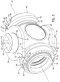
FIG. 1 is a perspective view of an embodiment of aball valve assembly 10. In certain embodiments, theball valve assembly 10 may be disposed along a well string, such as a landing string. For example, theball valve assembly 10 may be used as a retainer valve within a subsea landing string. In the illustrated embodiment, theball valve assembly 10 includes aninlet 12 positioned at afirst end portion 14 of theball valve assembly 10, and theball valve assembly 10 includes anoutlet 16 positioned at asecond end portion 18 of theball valve assembly 10. Theinlet 12 is configured to receive fluid (e.g., from a well), and theball valve assembly 10 is configured to control flow of the fluid through theball valve assembly 10 between theinlet 12 and theoutlet 16. Furthermore, theball valve assembly 10 includes a housing 19 (e.g., body) configured to house a ball. Thehousing 19 may be a solid forged block of material (e.g., steel), as illustrated, the housing may be cast from a suitable material (e.g., steel), or the housing may be formed by another suitable technique. In addition, the housing may be formed from a single piece of material, or the housing may be formed from multiple pieces of material coupled to one another. - As discussed in detail below, in certain embodiments, the ball of the
ball valve assembly 10 has a fluid pathway extending through the ball. The ball is configured to rotate between an open position and a closed position. The fluid pathway is configured to align with a fluid passage of theball valve assembly 10 while the ball is in the open position to enable fluid flow through theball valve assembly 10. In addition, the fluid pathway is configured to be offset from the fluid passage while the ball is in the closed position to block fluid flow through theball valve assembly 10. Furthermore, the ball valve assembly includes an annular seat configured to engage the ball. The ball valve assembly also includes a rotatable ring positioned on an opposite side of the annular seat from the ball, and the rotatable ring includes a first engagement feature (e.g., substantially flat surface). In addition, the ball valve assembly includes a non-rotatable ring positioned adjacent to the rotatable ring (e.g., on an opposite side of the rotatable ring from the annular seat). The ball valve also includes a drive plate non-rotatably coupled to the ball. Accordingly, the drive plate is configured to rotate with the ball between the open and closed positions. The drive plate includes a second engagement feature (e.g., substantially flat surface), and the second engagement feature of the drive plate is configured to engage the first engagement feature of the rotatable ring to drive the rotatable ring to rotate in response to rotation of the drive plate. Furthermore, the ball valve assembly includes bearing element(s) (e.g., spherical head pin(s), etc.) configured to drive the rotatable ring and the non-rotatable ring away from one another to compress the annular seat against the ball in response to rotation of the rotatable ring. - By way of example, as the ball rotates toward the open position, the drive plate, which is non-rotatably coupled to the ball, rotates with the ball. As the ball approaches the open position, the second engagement feature of the drive plate engages the first engagement feature of the rotatable ring. Further rotation of the ball causes the drive plate to drive the rotatable ring to rotate via engagement of the first and second engagement features. Rotation of the rotatable ring causes the bearing element(s) to drive the rotatable ring and the non-rotatable ring away from one another, thereby compressing the annular seat against the ball. Alternatively, as the ball rotates toward the closed position, the drive plate, which is non-rotatably coupled to the ball, rotates with the ball. As the ball approaches the closed position, the second engagement feature of the drive plate engages the first engagement feature of the rotatable ring. Further rotation of the ball causes the drive plate to drive the rotatable ring to rotate via engagement of the first and second engagement features. Rotation of the rotatable ring causes the bearing element(s) to drive the rotatable ring and the non-rotatable ring away from one another, thereby compressing the annular seat against the ball. Accordingly, as the ball rotates to the open position or to the closed position, the annular seat is compressed against the ball by mechanical force applied by the drive plate, the rotatable ring, and the bearing element(s) (e.g., alone or in combination with a force applied by pressurized fluid within the ball valve assembly, as discussed in detail below). As a result, the annular seat may be compressed with significantly more force than an annular seat in a ball valve assembly that uses fluid pressure alone to compress the annular seat against the ball. Therefore, the ball valve assembly disclosed herein may be used for applications having operational conditions that are unsuitable for a ball valve assembly in which the annular seat is compressed against the ball by application of fluid pressure alone.
-
FIG. 2 is a cross-sectional view of theball valve assembly 10 ofFIG. 1 , taken along line 2-2 ofFIG. 1 . In the illustrated embodiment, the housing 19 (e.g., body) of theball valve assembly 10 has afluid passage 20. As illustrated, thefluid passage 20 extends to theinlet 12 and to theoutlet 16. Theball valve assembly 10 also includes an adapter 22 (e.g., bonnet) coupled to thehousing 19. In the illustrated embodiment, theadapter 22 is coupled to thehousing 19 byfasteners 24, such as the illustrated bolts/nuts. However, in other embodiments, theadapter 22 may be coupled to thehousing 19 by any other suitable type of connection or combination of connections (e.g., alone or in combination with the fasteners 24). Furthermore, theball valve assembly 10 includes aball 26 disposed within thehousing 19 and having afluid pathway 28. As illustrated, theball 26 is retained within aninternal cavity 30 of thehousing 19 by theadapter 22. Theball 26 is configured to rotate about arotational axis 32 between an open position and a closed position. Thefluid pathway 28 of theball 26 is configured to align with thefluid passage 20 of thehousing 19 while theball 26 is in the open position to enable fluid flow through thefluid passage 20. In addition, thefluid pathway 28 of theball 26 is configured to be offset from thefluid passage 20 of thehousing 19 while theball 26 is in the closed position to substantially block fluid flow through thefluid passage 20. In the illustrated embodiment, astem 34 extends through theadapter 22 and non-rotatably couples to theball 26. Accordingly, rotation of thestem 34 about therotational axis 32 drives theball 26 to rotate between the open and closed positions. Thestem 34 may be driven to rotate by manual input and/or by an actuator, such as a hydraulic actuator, an electromechanical actuator, a pneumatic actuator, another suitable type of actuator, or a combination thereof. - In the illustrated embodiment, the
ball valve assembly 10 includes asealing system 36 configured to substantially block fluid flow through thefluid passage 20 while theball 26 is in the closed position and to substantially block fluid from flowing out of thefluid passage 20/fluid pathway 28 interface while theball 26 is in the open position. The sealingsystem 36 includes a first seat, such as the illustrated firstannular seat 38, and a second seat, such as the illustrated secondannular seat 40. Each annular seat is configured to engage theball 26. As discussed in detail below, each annular seat may be compressed against the ball (e.g., energized) while the ball is in the open position and/or while the ball is in the closed position. As illustrated, each annular seat is substantially aligned with thefluid passage 20 of thehousing 19. Accordingly, each annular seat is substantially coaxial with the fluid passage 20 (e.g., thefluid passage 20 and each annular seat have a common longitudinal axis 42). Each annular seat may be formed from any suitable material or combination of materials, such as rubber, a polymeric material, metal, another suitable material, or a combination thereof. For example, at least one annular seat may include an annular polymeric seal disposed within a metal seal retainer. Furthermore, in certain embodiments, the annular seat may include a lip seal (e.g., including a coil spring extending circumferentially about the annular seat). - Furthermore, the sealing
system 36 includes a firstrotatable ring 44 and a secondrotatable ring 46. As illustrated, the firstrotatable ring 44 is positioned on an opposite side of the firstannular seat 38 from theball 26 along thelongitudinal axis 42 of thefluid passage 20, and the secondrotatable ring 46 is positioned on an opposite side of the secondannular seat 40 from theball 26 along thelongitudinal axis 42 of thefluid passage 20. Each rotatable ring is configured to rotate about thelongitudinal axis 42 of thefluid passage 20, and each rotatable ring includes one or more engagement features, as discussed in detail below. As illustrated, each rotatable ring is substantially aligned with thefluid passage 20 of thehousing 19. Accordingly, each rotatable ring is substantially coaxial with the fluid passage 20 (e.g., thefluid passage 20 and each rotatable ring have a common longitudinal axis 42). - In addition, the sealing
system 36 includes a firstnon-rotatable ring 48 and a secondnon-rotatable ring 50. As illustrated, the firstnon-rotatable ring 48 is positioned adjacent to the firstrotatable ring 44 on an opposite side of the firstrotatable ring 44 from the firstannular seat 38 along thelongitudinal axis 42 of thefluid passage 20, and the secondnon-rotatable ring 50 is positioned adjacent to the secondrotatable ring 46 on an opposite side of the secondrotatable ring 46 from the secondannular seat 40 along thelongitudinal axis 42 of thefluid passage 20. As discussed in detail below, rotation of each non-rotatable ring about thelongitudinal axis 42 of thefluid passage 20 is blocked. As illustrated, each non-rotatable ring is substantially aligned with thefluid passage 20 of thehousing 19. Accordingly, each non-rotatable ring is substantially coaxial with the fluid passage 20 (e.g., thefluid passage 20 and each non-rotatable ring have a common longitudinal axis 42). - The sealing
system 36 of theball valve assembly 10 also includes afirst drive plate 52 non-rotatably coupled to theball 26 and asecond drive plate 54 non-rotatably coupled to theball 26. Each drive plate is configured to rotate with the ball. For example, in certain embodiments, the ball may have polygonal protrusions, and each drive plate may have a corresponding polygonal recess configured to receive a respective polygonal protrusion of the ball. Engagement of each polygonal protrusion of the ball with the corresponding polygonal recess of the respective drive plate non-rotatably couples the respective drive plate to the ball. As discussed in detail below, each drive plate includes one or more engagement features, and each engagement feature of the drive plate is configured to engage a corresponding engagement feature of a respective rotatable ring (e.g., as the ball approaches the open position and/or the closed position). While an engagement feature of a drive plate is engage with a corresponding engagement feature of a rotatable ring, rotation of the drive plate drives the rotatable ring to rotate. - Furthermore, the sealing
system 36 includes one or more first bearing elements and one or more second bearing elements. The first bearing element(s) are configured to drive the firstrotatable ring 44 and the firstnon-rotatable ring 48 away from one another to compress (e.g., energize) the firstannular seat 38 against theball 26 in response to rotation of the firstrotatable ring 44. In addition, the second bearing element(s) are configured to drive the secondrotatable ring 46 and the secondnon-rotatable ring 50 away from one another to compress (e.g., energize) the secondannular seat 40 against theball 26 in response to rotation of the secondrotatable ring 46. Accordingly, as theball 26 rotates to the open position and/or to the closed position, each annular seat is compressed against the ball by mechanical force applied by the drive plates, the rotatable rings, and the bearing elements (e.g., alone or in combination with a force applied by pressurized fluid within the ball valve assembly, as discussed in detail below). As a result, each annular seat may be compressed with significantly more force than an annular seat in a ball valve assembly that uses fluid pressure alone to compress the annular seat against the ball. Therefore, the ball valve assembly disclosed herein may be used for applications having operational conditions that are unsuitable for a ball valve assembly in which the annular seats are compressed against the ball by application of fluid pressure alone. -
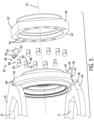
FIG. 3 is a perspective view of theball 26 and thesealing system 36 of theball valve assembly 10 ofFIG. 1 , in which theball 26 is in the closed position. In the illustrated embodiment, theball 26 has arecess 56 configured to receive a corresponding protrusion of the stem. Therecess 56 of theball 26 and the protrusion of the stem are shaped to non-rotatably couple the stem to theball 26 while the protrusion is engaged with therecess 56. In the illustrated embodiment, therecess 56 is substantially rectangular. However, in other embodiments, the recess may have any other suitable shape (e.g., elliptical, hexagonal, star-shaped, etc.). Furthermore, in certain embodiments, the stem and the ball may be non-rotatably coupled to one another by any other suitable connection (e.g., welded connection, pinned connection, integrally formed as one unit, etc.). Because the stem and theball 26 are non-rotatably coupled to one another, rotation of the stem drives theball 26 to rotate (e.g., between the illustrated closed position and the open position). - In the illustrated embodiment, the
ball 26 includes a firstpolygonal protrusion 55, and thefirst drive plate 52 includes a corresponding polygonal recess 57 (e.g., opening) configured to receive the firstpolygonal protrusion 55 of theball 26. Engagement of the firstpolygonal protrusion 55 of theball 26 with the correspondingpolygonal recess 57 of thefirst drive plate 52 non-rotatably couples thefirst drive plate 52 to theball 26. While the first protrusion and the corresponding recess are polygonal in the illustrated embodiment, in other embodiments, the protrusion and the corresponding recess may have any other suitable shape (e.g., elliptical, star-shaped, etc.). Furthermore, in certain embodiments, the first drive plate may be non-rotatably coupled to the ball by another suitable connection (e.g., alone or in combination with the protrusion/recess connection), such as a fastener connection, a welded connection, an adhesive connection, other suitable connection(s), or a combination thereof. Furthermore, while the first drive plate is directly non-rotatably coupled to the ball in the illustrated embodiment, in other embodiments, the first drive plate may be non-rotatably coupled to the ball via another suitable structure, such as the stem. - In the illustrated embodiment, the sealing
system 36 of theball valve assembly 10 includesanti-rotation plates 58 configured to block rotation of the non-rotatable rings. As illustrated, eachanti-rotation plate 58 has a substantially flat surface 60 (e.g., second substantially flat surface, fourth substantially flat surface), the firstnon-rotatable ring 48 has corresponding substantially flat surfaces 62 (e.g., first substantially flat surfaces), and the secondnon-rotatable ring 50 has corresponding substantially flat surface 62 (e.g., third substantially flat surfaces). The substantiallyflat surface 60 of eachanti-rotation plate 58 is configured to contact a corresponding substantiallyflat surface 62 of a respective non-rotatable ring to block rotation of the non-rotatable ring about thelongitudinal axis 42. While engagement of the substantially flat surfaces blocks rotation of the non-rotatable rings about thelongitudinal axis 42, the substantially flat surfaces enable each non-rotatable ring to move along thelongitudinal axis 42. As a result, the first rotatable ring and the first non-rotatable ring may move away from one another in response to rotation of the first rotatable ring, and the second rotatable ring and the second non-rotatable ring may move away from one another in response to rotation of the second rotatable ring. In the illustrated embodiment, eachanti-rotation plate 58 is coupled to the housing by one ormore fasteners 64. However, in other embodiments, at least one anti-rotation plate may be coupled to the housing by other suitable type(s) of connection(s) (e.g., alone or in combination with the fastener(s)), such as a welded connection, an adhesive connection, a press-fit connection, other suitable type(s) of connection(s), or a combination thereof. Furthermore, while two anti-rotation plates are used to block rotation of each non-rotatable ring in the illustrated embodiment, in other embodiments, more or fewer anti-rotation plates (e.g., 0, 1, 3, 4, or more) may be used to block rotation of at least one non-rotatable ring. For example, in certain embodiments, at least one substantially flat surface may be formed within the housing and configured to engage at least one corresponding substantially flat surface of at least one non-rotatable ring. Furthermore, while substantially flat surfaces are used to block rotation of each non-rotatable ring in the illustrated embodiment, in other embodiments, other suitable surface(s) (e.g., formed on anti-rotation plate(s), formed within the housing, etc.) and/or device(s) (e.g., protrusion(s)/recess(es), pin(s), fastener(s), etc.) may be used to block rotation of at least one non-rotatable ring (e.g., alone or in combination with the substantially flat surface(s)). - In the illustrated embodiment, the first
rotatable ring 44 includes two engagement features (e.g., first engagement features), the secondrotatable ring 46 includes two engagement features (e.g., second engagement features), thefirst drive plate 52 includes two engagement features (e.g., second engagement features, third engagement features), and thesecond drive plate 54 includes two engagement features (e.g., fourth engagement features). As illustrated, with theball 26 in the illustrated closed position, oneengagement feature 66 of thefirst drive plate 52 is in contact with acorresponding engagement feature 68 of the firstrotatable ring 44, and anotherengagement feature 70 of thefirst drive plate 52 is in contact with acorresponding engagement feature 72 of the secondrotatable ring 46. Theball 26 may rotate in a firstrotational direction 74 about therotational axis 32 from the open position toward the illustrated closed position. As theball 26 approaches the closed position, theengagement feature 66 of thefirst drive plate 52 engages thecorresponding engagement feature 68 of the firstrotatable ring 44, and theengagement feature 70 of thefirst drive plate 52 engages thecorresponding engagement feature 72 of the secondrotatable ring 46. Further rotation of theball 26 in the firstrotational direction 74 causes thefirst drive plate 52 to drive the rotatable rings to rotate about thelongitudinal axis 42 via engagement of the engagement features of thefirst drive plate 52 and the rotatable rings. Rotation of the firstrotatable ring 44 from a first position (e.g., in which the engagement features of the first drive plate and the first rotatable ring are not engaged with one another) to a second position (e.g., in which the first rotatable ring is rotated about the longitudinal axis) causes the respective bearing element(s) to drive the firstrotatable ring 44 and the firstnon-rotatable ring 48 away from one another along thelongitudinal axis 42, thereby compressing the firstannular seat 38 against theball 26. In addition, rotation of the secondrotatable ring 46 from a first position (e.g., in which the engagement features of the first drive plate and the second rotatable ring are not engaged with one another) to a second position (e.g., in which the second rotatable ring is rotated about the longitudinal axis) causes the respective bearing element(s) to drive the secondrotatable ring 46 and the secondnon-rotatable ring 50 away from one another along thelongitudinal axis 42, thereby compressing the secondannular seat 40 against theball 26. Accordingly, as the ball rotates to the closed position, each annular seat is compressed against the ball by mechanical force applied by the first drive plate, the rotatable rings, and the bearing elements (e.g., alone or in combination with a force applied by pressurized fluid within the ball valve assembly, as discussed in detail below). As a result, each annular seat may be compressed with significantly more force than an annular seat in a ball valve assembly that uses fluid pressure alone to compress the annular seat against the ball. Therefore, the ball valve assembly disclosed herein may be used for applications having operational conditions that are unsuitable for a ball valve assembly in which the annular seats are compressed against the ball by application of fluid pressure alone. -
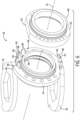
FIG. 4 is a bottom view of theball 26 and thesealing system 36 ofFIG. 3 , in which theball 26 is in an open position. In the illustrated embodiment, theball 26 includes a secondpolygonal protrusion 75, and thesecond drive plate 54 includes a corresponding polygonal recess 77 (e.g., opening) configure to receive the secondpolygonal protrusion 75 of theball 26. Engagement of the secondpolygonal protrusion 75 of theball 26 with the correspondingpolygonal recess 77 of thesecond drive plate 54 non-rotatably couples thesecond drive plate 54 to theball 26. While the second protrusion and the corresponding recess are polygonal in the illustrated embodiment, in other embodiments, the protrusion and the corresponding recess may have any other suitable shape (e.g., elliptical, star-shaped, etc.). Furthermore, in certain embodiments, the second drive plate may be non-rotatably coupled to the ball by another suitable connection (e.g., alone or in combination with the protrusion/recess connection), such as a fastener connection, a welded connection, an adhesive connection, other suitable connection(s), or a combination thereof. - As illustrated, with the
ball 26 in the illustrated open position, oneengagement feature 76 of thesecond drive plate 54 is in contact with acorresponding engagement feature 78 of the firstrotatable ring 44, and anotherengagement feature 80 of thesecond drive plate 54 is in contact with acorresponding engagement feature 82 of the secondrotatable ring 46. Theball 26 may rotate in a secondrotational direction 84 about the rotational axis from the closed position toward the illustrated open position. As theball 26 approaches the open position, theengagement feature 76 of thesecond drive plate 54 engages thecorresponding engagement feature 78 of the firstrotatable ring 44, and theengagement feature 80 of thesecond drive plate 54 engages thecorresponding engagement feature 82 of the secondrotatable ring 46. Further rotation of theball 26 in the secondrotational direction 84 causes thesecond drive plate 54 to drive the rotatable rings to rotate about thelongitudinal axis 42 via engagement of the engagement features of thesecond drive plate 54 and the rotatable rings. Rotation of the firstrotatable ring 44 from a first position (e.g., in which the engagement features of the second drive plate and the first rotatable ring are not engaged with one another) to a second position (e.g., in which the first rotatable ring is rotated about the longitudinal axis) causes the respective bearing element(s) to drive the firstrotatable ring 44 and the firstnon-rotatable ring 48 away from one another along thelongitudinal axis 42, thereby compressing the firstannular seat 38 against theball 26. In addition, rotation of the secondrotatable ring 46 from a first position (e.g., in which the engagement features of the second drive plate and the second rotatable ring are not engaged with one another) to a second position (e.g., in which the second rotatable ring is rotated about the longitudinal axis) causes the respective bearing element(s) to drive the secondrotatable ring 46 and the secondnon-rotatable ring 50 away from one another along thelongitudinal axis 42, thereby compressing the secondannular seat 40 against theball 26. Accordingly, as the ball rotates to the open position, each annular seat is compressed against the ball by mechanical force applied by the second drive plate, the rotatable rings, and the bearing elements (e.g., alone or in combination with a force applied by pressurized fluid within the ball valve assembly, as discussed in detail below). As a result, each annular seat may be compressed with significantly more force than an annular seat in a ball valve assembly that uses fluid pressure alone to compress the annular seat against the ball. Therefore, the ball valve assembly disclosed herein may be used for applications having operational conditions that are unsuitable for a ball valve assembly in which the annular seats are compressed against the ball by application of fluid pressure alone. - In the illustrated embodiment, each engagement feature includes a substantially flat surface configured to engage the substantially flat surface of a corresponding engagement feature. For example, in certain embodiments, the substantially flat surface of each engagement feature may be angled (e.g., about 1 degree to about 10 degrees, about 2 degrees to about 7 degrees, or about 5 degrees) relative to a radial axis of the respective ring/plate to facilitate engagement of the respective engagement features. While each engagement feature includes a substantially flat surface in the illustrated embodiment, in other embodiments, at least one engagement feature may include another suitable surface and/or device (e.g., rounded surface, protrusion configured to engage a recess, etc.) configured to engage a corresponding engagement feature.
- While the non-rotatable rings are configured to move along the longitudinal axis in the illustrated embodiment, in other embodiments, movement of at least one non-rotatable ring along the longitudinal axis may be blocked. In such embodiments, the bearing element(s) may drive the respective rotatable ring(s) away from the respective non-rotatable ring(s) along the longitudinal axis in response to rotation of the rotatable ring(s). Furthermore, while each non-rotatable ring is positioned on an opposite side of the respective rotatable ring from the respective annular seat in the illustrated embodiment, in other embodiments, at least one non-rotatable ring may be positioned between the respective annular seat and the respective rotatable ring. In addition, as previously discussed, in the illustrated embodiment, the
first drive plate 52 and the rotatable rings are configured such that thefirst drive plate 52 drives the rotatable rings to rotate as theball 26 approaches the closed position, and thesecond drive plate 54 and the rotatable rings are configured such that thesecond drive plate 54 drives the rotatable rings to rotate as theball 26 approaches the open position. However, in other embodiments, the first drive plate and the rotatable rings may be configured such that the first drive plate drives the rotatable rings to rotate as the ball approaches the open position, and the second drive plate and the rotatable rings may be configured such that the second drive plate drives the rotatable rings to rotate as the ball approaches the closed position. Furthermore, in certain embodiments, one of the drive plates may be omitted. In such embodiments, the rotatable rings may only be driven to rotate as the ball approaches the closed position or the open position. In addition, in certain embodiments, the sealing system may include two driving plates that cooperate to drive the rotatable rings to rotate (e.g., as the ball approaches the closed position or the open position). Furthermore, while the sealing system includes two annular seats, two rotatable rings, and two non-rotatable rings in the illustrated embodiment, in other embodiments, the sealing system may include a single annular seat, rotatable ring, and non-rotatable ring. In such embodiments, only one annular seat may be compressed against the ball by mechanical force, and each driving plate may only include a single engagement feature. -
FIG. 5 is an exploded view of a portion of the sealingsystem 36 ofFIG. 3 . As previously discussed, the sealingsystem 36 includes bearing element(s) 86 configured to drive the firstrotatable ring 44 and the firstnon-rotatable ring 48 away from one another to compress the firstannular seat 38 against theball 26 in response to rotation of the firstrotatable ring 44. In the illustrated embodiment, the bearingelements 86 include spherical head pins 88. Eachspherical head pin 88 includes ashaft 90 and a hemi-spherical head 92. Theshaft 90 of eachspherical head pin 88 is configured to be disposed within a correspondingrecess 94 of the firstnon-rotatable ring 48. In the illustrated embodiment, eachspherical head pin 88 is coupled to the firstnon-rotatable ring 48 via an interference fit between theshaft 90 of thespherical head pin 88 and thecorresponding recess 94. However, in other embodiments, at least one spherical head pin may be coupled to the first non-rotatable ring by another suitable connection (e.g., a threaded connection, a welded connection, a pinned connection, an adhesive connection, a shrink-fit connection, etc.). - Furthermore, as discussed in detail below, the hemi-
spherical head 92 of eachspherical head pin 88 is configured to selectively engage a respective recess within the firstrotatable ring 44. While the hemi-spherical heads 92 of the spherical head pins 88 are engaged with the respective recesses of the firstrotatable ring 44, the firstrotatable ring 44 and the firstnon-rotatable ring 48 may be positioned a minimum distance away from one another along the longitudinal axis 42 (e.g., touching one another, separated by a small gap, etc.). In response to rotation of the firstrotatable ring 44 from the first position to the second position, the hemi-spherical heads 92 of the spherical head pins 88 disengage the respective recesses of the firstrotatable ring 44, thereby driving the firstrotatable ring 44 and the firstnon-rotatable ring 48 away from one another along thelongitudinal axis 42. As used herein, "away from one another" refers to increasing the distance between the rotatable and non-rotatable rings and does not necessarily include movement of both rings (e.g., in embodiments in which movement of the non-rotatable ring along the longitudinal axis is blocked). - As previously discussed, in the illustrated embodiment, each
spherical head pin 88 is coupled to the firstnon-rotatable ring 48, and each respective recess is formed within the firstrotatable ring 44. However, in other embodiments, at least one spherical head pin may be coupled to the first rotatable ring, and at least one respective recess may be formed within the first non-rotatable ring. In addition, while the bearingelements 86 include spherical head pins 88 in the illustrated embodiment, in other embodiments, the bearing elements may include any other suitable type(s) of bearing element(s) (e.g., alone or in combination with the spherical head pin(s)), such as ball bearing(s) (e.g., captured by at least one of the rings), wedge(s) (e.g., formed on at least one of the rings), roller(s) (e.g., captured by at least one of the rings), other suitable type(s) of bearing element(s), or a combination thereof. Furthermore, in the illustrated embodiment, the sealingsystem 36 includes ten bearingelements 86 disposed circumferentially about the longitudinal axis 42 (e.g., flow path through the ball valve assembly). However, in other embodiments, the sealing system may include more or fewer bearing elements (e.g., 1, 2, 4, 6, 8, 12, 14, 20, or more) arranged in any suitable configuration. While first bearing element(s) configured to drive the first rotatable ring and the first non-rotatable ring away from one another are disclosed above, in certain embodiments, the sealing system may include second bearing element(s) configured to drive the second rotatable ring and the second non-rotatable ring away from one another. Such second bearing element(s) may include any of the features and/or variations disclosed herein with regard to the first bearing element(s). In addition, the first and second bearing elements may be the same as one another or different from one another. -
FIG. 6 is another exploded view of a portion of the sealingsystem 36 ofFIG. 3 . As previously discussed, in the illustrated embodiment, recesses 96 are formed within the firstrotatable ring 44. Eachrecess 96 is configured to receive a respective bearing element (e.g., spherical head pin). In the illustrated embodiment, eachrecess 96 has a substantially conical shape (e.g., with straight walls, with curved walls, etc.). However, in other embodiments, at least one recess may have another suitable shape (e.g., hemi-spherical, polygonal, etc.). The shape of each recess is configured to receive a respective bearing element while the bearing element is aligned with the recess. Accordingly, while the firstrotatable ring 44 is in the first position, the bearing elements are engaged with/disposed within therespective recesses 96, thereby establishing the minimum separate distance between the firstrotatable ring 44 and the firstnon-rotatable ring 48. In addition, the shape of eachrecess wall 98 is configure to drive the rotatable and non-rotatable rings away from one another in response to movement that offsets the recess from the respective bearing element. For example, in response to rotation of the firstrotatable ring 44 to the second position, each bearing element may disengage the respective recess 96 (e.g., while maintaining contact with thewall 98 of the recess 96). Accordingly, as the firstrotatable ring 44 rotates toward the second position, the bearing elements disengage therespective recesses 96, thereby separating the firstrotatable ring 44 from the firstnon-rotatable ring 48, which compresses the firstannular seat 38 against the ball. As used herein with respect to the bearing elements/recesses, "disengage"/"disengaged" refers to a bearing element that is not fully engaged with the respective recess. Accordingly, a disengaged bearing element includes a bearing element that is partially disengaged from the respective recess (e.g., in which the bearing element maintains contact with the wall of the recess) and a bearing element that is fully disengaged from the respective recess (e.g., in which the bearing element is in contact with the surface of the rotatable ring surrounding the recess). -
FIG. 7 is a cross-sectional view of a portion of the sealingsystem 36 ofFIG. 3 , in which aspherical head pin 88 is engaged with arespective recess 96. While the hemi-spherical head 92 of eachspherical head pin 88 is engaged with arespective recess 96 of the firstrotatable ring 44, the firstrotatable ring 44 and the firstnon-rotatable ring 48 are positioned a minimum distance away from one another along the longitudinal axis (e.g., touching one another, separated by a small gap, etc.). In response to rotation of the firstrotatable ring 44 from the first position to the second position, the hemi-spherical head 92 of eachspherical head pin 88 disengages therespective recess 96 of the firstrotatable ring 44, thereby driving the firstrotatable ring 44 and the firstnon-rotatable ring 48 away from one another along the longitudinal axis. -
FIG. 8 is a cross-sectional view of a portion of the sealingsystem 36 ofFIG. 3 , in which thespherical head pin 88 is disengaged from therespective recess 96. As previously discussed, in response to rotation of the firstrotatable ring 44 to the second position, eachspherical head pin 88 disengages therespective recess 96. Accordingly, as the firstrotatable ring 44 rotates toward the second position, the spherical head pins 88 disengage therespective recesses 96, thereby driving the firstrotatable ring 44 and the firstnon-rotatable ring 48 away from one another, which compresses the firstannular seat 38 against the ball. Accordingly, as the ball rotates to the open or the closed position, each annular seat is compressed against the ball by mechanical force applied by the first/second drive plate, the rotatable ring(s), and the bearing element(s) (e.g., alone or in combination with a force applied by pressurized fluid within the ball valve assembly, as discussed in detail below). As a result, each annular seat may be compressed with significantly more force than an annular seat in a ball valve assembly that uses fluid pressure alone to compress the annular seat against the ball. Therefore, the ball valve assembly disclosed herein may be used for applications having operational conditions that are unsuitable for a ball valve assembly in which the annular seats are compressed against the ball by application of fluid pressure alone. - Furthermore, in the illustrated embodiment, the hemi-
spherical head 92 of eachspherical head pin 88 maintains contact with thewall 98 of therespective recess 96 while the firstrotatable ring 44 is in the second position. Due to the shape of thewall 98 of eachrecess 96, the respectivespherical head pin 88 may be urged into engagement with therecess 96 while the hemi-spherical head 92 of thespherical head pin 88 is in contact with thewall 98 of therecess 96. Accordingly, as theball 26 rotates away from the open position or the closed position and the engagement features disengage one another, contact between the spherical head pins 88 and therecesses 96 may drive the firstrotatable ring 44 to rotate from the second position to the first position. However, in other embodiments, the bearing element(s) may contact the surface surrounding the recess(es) while the rotatable ring is in the second position, or the wall of each recess may be shaped to block re-engagement of the respective bearing element with the recess. In such embodiments, the bearing element(s) may remain disengaged from the respective recess(es) as the ball rotates away from the open/closed position and the engagement features disengaged one another. - While utilizing mechanical force to compress each annular seat is disclosed above, in certain embodiments, the ball valve assembly may utilize a combination of mechanical and hydraulic force to compress at least one annular seat against the ball. For example, in the illustrated embodiment, fluid within the
fluid passage 20 may urge the firstannular seat 38, the firstrotatable ring 44, and the firstnon-rotatable ring 48 away from the ball via application of pressure to afirst area 100 of the firstannular seat 38. As illustrated, thefirst area 100 of the firstannular seat 38 corresponds to the portion of the firstannular seat 38 that faces the ball and is positioned radially inward from the portion of the firstannular seat 38 that contacts the ball. In addition, the fluid within thefluid passage 20 may urge the firstannular seat 38, the firstrotatable ring 44, and the firstnon-rotatable ring 48 toward the ball via application of pressure to asecond area 102 of the firstnon-rotatable ring 48. As illustrated, thesecond area 102 of the firstnon-rotatable ring 48 corresponds to the portion of the firstnon-rotatable ring 48 that faces away from the ball and is positioned radially inward from the portion of the firstnon-rotatable ring 48 that contacts thehousing 19. In the illustrated embodiment, thesecond area 102 is greater than thefirst area 100. Accordingly, a net force is applied to the firstannular seat 38, the firstrotatable ring 44, and the firstnon-rotatable ring 48 in a direction toward the ball, thereby further compressing the firstannular seat 38 against the ball while the ball is in the open or closed position. While the hydraulic force is disclosed above with regard to the firstannular seat 38, the hydraulic force may be additionally or alternatively used to compress the second annular seat against the ball. - Additionally or alternatively, the sealing system may include spring(s) (e.g., coil spring(s), leaf spring(s), etc.) configured to urge at least one annular seat/rotatable ring/non-rotatable ring toward the ball. For example, in certain embodiments, one or more springs may be positioned between the housing and at least one respective non-rotatable ring. The spring(s) enable movement of the annular seat(s), the rotatable ring(s), and the non-rotatable ring(s) to facilitate insertion of the ball during assembly of the ball valve assembly. In addition, the spring(s) urge the bearing element(s) into engagement with the respective recess(es). For example, in embodiments including spherical head pin(s), the force of the spring(s) may urge the hemi-spherical head of each spherical head pin to move along the wall of the respective recess until the spherical head pin is engaged (e.g., fully engaged) with the respective recess.
- Technical effects of the disclosure include compressing an annular seat of a ball valve assembly with increased force to enable the ball valve assembly to be used for additional applications. For example, as previously discussed, rotation of the rotatable ring causes the bearing element(s) to drive the rotatable ring and the non-rotatable ring away from one another, thereby compressing the annular seat against the ball. Accordingly, as the ball rotates to the open position or to the closed position, the annular seat is compressed against the ball by mechanical force applied by the drive plate, the rotatable ring, and the bearing element(s) (e.g., alone or in combination with a force applied by pressurized fluid within the ball valve assembly). As a result, the annular seat may be compressed with significantly more force than an annular seat in a ball valve assembly that uses fluid pressure alone to compress the annular seat against the ball. Therefore, the ball valve assembly disclosed herein may be used for applications having operational conditions that are unsuitable for a ball valve assembly in which the annular seat is compressed against the ball by application of fluid pressure alone.
- While only certain features have been illustrated and described herein, many modifications and changes will occur to those skilled in the art. It is, therefore, to be understood that the appended claims are intended to cover all such modifications and changes that fall within the scope of these claims.
Claims (13)
- A ball valve assembly, comprising:a ball (26) configured to rotate between an open position and a closed position;an annular seat (38) configured to engage the ball (26);a rotatable ring (44) positioned on an opposite side of the annular seat (38) from the ball (26), wherein the rotatable ring (46) comprises at least one first engagement feature (68);a non-rotatable ring (50) positioned adjacent to the rotatable ring (44);characterized in that the ball valve assembly comprises a drive plate (52) non-rotatably coupled to the ball (26), wherein the drive plate (52) is configured to rotate with the ball (26), the drive plate (52) comprises at least one second engagement feature (66), and the at least one second engagement feature (66) of the drive plate (52) is configured to engage the at least one first engagement feature (68) of the rotatable ring (44) to drive the rotatable ring (44) to rotate in response to rotation of the drive plate (52); andat least one bearing element (86) configured to drive the rotatable ring (44) and the non-rotatable ring (50) away from one another to compress the annular seat (38) against the ball (26) in response to rotation of the rotatable ring (44), wherein the at least one bearing element (86) comprises a spherical head pin (88) configured to selectively engage a respective recess (94), and the spherical head pin (88) is configured to disengage the respective recess (94) in response to rotation of the rotatable ring (44) to drive the rotatable ring (44) and the non-rotatable ring (50) away from one another.
- The ball valve assembly of claim 1, wherein the spherical head pin (88) is coupled to the non-rotatable ring (50), and the respective recess (94) is formed within the rotatable ring (44).
- The ball valve assembly of claim 1, wherein the at least one bearing element (86) comprises a plurality of bearing elements disposed circumferential about a flow path (20) through the ball valve assembly.
- The ball valve assembly of claim 3, wherein each bearing element (86) of the plurality of bearing elements comprises a spherical head pin (88).
- The ball valve assembly of claim 1, comprising a second drive plate (54) non-rotatably coupled to the ball (26), wherein the second drive plate (54) is configured to rotate with the ball (26), the second drive plate (54) comprises at least one third engagement feature (76 80), the at least one first engagement feature (68) of the rotatable ring (44) comprises a plurality of first engagement features, and the at least one third engagement feature (76, 80) of the second drive plate (54) is configured to engage one first engagement feature (68) of the plurality of first engagement features of the rotatable ring (44) to drive the rotatable ring (44) to rotate in response to rotation of the second drive plate (54).
- The ball valve assembly of claim 1, comprising an anti-rotation plate (58), wherein the non-rotatable ring (50) comprises a first substantially flat surface (62), the anti-rotation plate (58) comprises a second substantially flat surface (60), and the second substantially flat surface (60) is configured to engage the first substantially flat surface (62) to block rotation of the non-rotatable ring (50).
- The ball valve assembly of claim 1, wherein the at least one first engagement feature (68) of the rotatable ring (44) comprises a first substantially flat surface, and the at least one second engagement feature of the drive plate (52) comprises a second substantially flat surface.
- The ball valve assembly of any preceding claim, further comprising:a housing (19) having a fluid passage (20), wherein the ball is disposed within the housing (19), the ball comprising a fluid pathway (28) configured to align with the fluid passage (20) of the housing (19) while the ball (26) is in the open position to enable fluid flow through the fluid passage (20), and the fluid pathway (28) of the ball (26) being configured to be offset from the fluid passage (20) of the housing (19) while the ball (26) is in the closed position to substantially block fluid flow through the fluid passage (20);wherein the annular seat (38) is substantially aligned with the fluid passage (20) of the housing (19) and the rotatable ring (44) is configured to rotate about the longitudinal axis (42) of the fluid passage (20), wherein rotation of the non-rotatable ring (48) about the longitudinal axis (42) of the fluid passage (20) is blocked;wherein the at least one second engagement feature (66) of the drive plate (52) is configured to engage the at least one first engagement feature (68) of the rotatable ring (44) to drive the rotatable ring (44) to rotate from a first position to a second position in response to rotation of the drive plate (52), the annular seat (38) being compressed against the ball (26) in response to rotation of the rotatable ring (44) toward the second position.
- The ball valve assembly of claim 8 wherein the spherical head pin (88) configured to engage the respective recess (94) while the rotatable ring (44) is in the first position and to disengage the respective recess (94) while the rotatable ring (44) is in the second position.
- The ball valve assembly of any of claims 1 to 7, whereinthe annular seat comprises a first annular seat (38) configured to engage a first side of the ball (26) and a second annular seat (40) configured to engage a second side of the ball (26), opposite the first side of the ball (26);the rotatable ring comprises a first rotatable ring (44) positioned on an opposite side of the first annular seat (38) from the ball (26) and a second rotatable ring (46) positioned on an opposite side of the second annular seat (40) from the ball (26), wherein the first rotatable ring comprises at least one first engagement feature and the second rotatable ring comprises at least one first engagement feature;the non-rotatable ring comprises a first non-rotatable ring (48) positioned adjacent to the first rotatable ring (44) and a second non-rotatable ring (50) positioned adjacent to the second rotatable ring (46);the drive plate (52) comprises a plurality of second engagement features (66), one of the plurality of second engagement features (66) of being configured to engage the at least one first engagement feature (68) of the first rotatable ring (44) to drive the first rotatable ring (44) to rotate in response to rotation of the drive plate (52), and another of the plurality of second engagement features (66) of the drive plate is configured to engage the at least one first engagement feature (66) of the second rotatable ring (46) to drive the second rotatable ring (46) to rotate in response to rotation of the drive plate (52); andwherein the at least one bearing element comprises at least one first bearing element (86) configured to drive the first rotatable ring (44) and the first non-rotatable ring (48) away from one another to compress the first annular seat (38) against the ball (26) in response to rotation of the first rotatable ring (44) and at least one second bearing element configured to drive the second rotatable ring (46) and the second non-rotatable ring (50) away from one another to compress the second annular seat (40) against the ball in response to rotation of the second rotatable ring (46).
- The ball valve assembly of claim 10, wherein each of the at least one first and second bearing elements (86) comprise a spherical head pin (88) configured to selectively engage a respective recess (94), and to disengage the respective recess in response to rotation of the first and second rotatable rings (44, 46)
- The ball valve assembly of claim 10, when dependent on claim 6 the anti-rotation plate comprising a first anti-rotation plate configured to block rotation of the first non-rotatable ring (44) and a second anti-rotation plate configured to block rotation of the second non-rotatable ring.
- The ball valve assembly of claim 10, when dependent on claim 5, wherein the second drive plate (52) comprises a plurality of third engagement features (76, 80), and the first and second rotatable rings (44 46) comprise a plurality of first engagement features (68)wherein one of the plurality of third engagement features (76, 80) of the second drive plate (52) is configured to engage one of the plurality of first engagement features (68) of the first rotatable ring (44) and another of the plurality of third engagement features (68) of the second drive plate (52) is configured to engage one of the plurality of first engagement features (68) of the second rotatable ring (46) to drive the first and second rotatable rings (44, 46) to rotate in response to rotation of the second drive plate (52).
Applications Claiming Priority (2)
| Application Number | Priority Date | Filing Date | Title |
|---|---|---|---|
| EP20425005 | 2020-02-03 | ||
| PCT/US2021/016178 WO2021158524A1 (en) | 2020-02-03 | 2021-02-02 | Ball valve assembly |
Publications (3)
| Publication Number | Publication Date |
|---|---|
| EP4100670A1 EP4100670A1 (en) | 2022-12-14 |
| EP4100670A4 EP4100670A4 (en) | 2024-04-10 |
| EP4100670B1 true EP4100670B1 (en) | 2025-06-25 |
Family
ID=69770849
Family Applications (1)
| Application Number | Title | Priority Date | Filing Date |
|---|---|---|---|
| EP21750235.0A Active EP4100670B1 (en) | 2020-02-03 | 2021-02-02 | Ball valve assembly |
Country Status (3)
| Country | Link |
|---|---|
| US (2) | US12031643B2 (en) |
| EP (1) | EP4100670B1 (en) |
| WO (1) | WO2021158524A1 (en) |
Family Cites Families (9)
| Publication number | Priority date | Publication date | Assignee | Title |
|---|---|---|---|---|
| US2863629A (en) * | 1956-08-02 | 1958-12-09 | Hydril Co | Valve |
| US3254873A (en) | 1962-12-17 | 1966-06-07 | Hydril Co | Valve seal expansion or displacement compensation |
| JPS5154091Y2 (en) * | 1971-04-07 | 1976-12-24 | ||
| US5004005A (en) * | 1989-08-07 | 1991-04-02 | Graves John G | Combination valve |
| US5676347A (en) * | 1995-08-31 | 1997-10-14 | Knox; Granville S. | Valve with adjustably pressurized sealing gaskets |
| US5549275A (en) * | 1995-08-31 | 1996-08-27 | Knox; Granville S. | Valve with adjustably pressurized sealing gaskets |
| JP3023661B2 (en) * | 1996-10-25 | 2000-03-21 | 大明商事株式会社 | valve |
| JPH11351420A (en) | 1998-06-09 | 1999-12-24 | Sekisui Chem Co Ltd | Ball valve |
| CN206655981U (en) | 2017-04-25 | 2017-11-21 | 浙江宝丰阀门有限公司 | Stainless steel integrated ball valve with good airproof performance |
-
2021
- 2021-02-02 WO PCT/US2021/016178 patent/WO2021158524A1/en not_active Ceased
- 2021-02-02 EP EP21750235.0A patent/EP4100670B1/en active Active
- 2021-02-02 US US17/759,565 patent/US12031643B2/en active Active
-
2024
- 2024-07-08 US US18/765,985 patent/US12359733B2/en active Active
Also Published As
| Publication number | Publication date |
|---|---|
| WO2021158524A1 (en) | 2021-08-12 |
| US12031643B2 (en) | 2024-07-09 |
| US20230250887A1 (en) | 2023-08-10 |
| EP4100670A1 (en) | 2022-12-14 |
| US20240360907A1 (en) | 2024-10-31 |
| EP4100670A4 (en) | 2024-04-10 |
| US12359733B2 (en) | 2025-07-15 |
Similar Documents
| Publication | Publication Date | Title |
|---|---|---|
| US6966537B2 (en) | Valve with seat assembly | |
| US4264054A (en) | Metal-to-metal seat hub seals | |
| CN101910698B (en) | Seal assembly for use with valves having a two-piece cage | |
| US7931251B2 (en) | Expanding gate valve | |
| US5727775A (en) | Gate valve with dual seal rings on a unitary seat ring | |
| SG191529A1 (en) | Valve vented redundant stem seal system | |
| WO2003093705A1 (en) | Ball valve assembly | |
| CN112969877B (en) | Valve with differential pressure valve seat | |
| CA2931760C (en) | Dual seal fire safe stem packing orientation | |
| EP3589870B1 (en) | Double positive isolation ball valve | |
| US10578229B2 (en) | Flexible stem bellow assembly | |
| US11796070B2 (en) | Ball valve assembly | |
| US7604056B2 (en) | Downhole valve and method of making | |
| EP4100670B1 (en) | Ball valve assembly | |
| US9046098B2 (en) | Face sealing annular valve for a fluid-working machine | |
| US20200132212A1 (en) | No-bolt valve assembly system | |
| EP3491275B1 (en) | Shutoff seal for high temperature pressure balance valve and related methods | |
| US12345345B2 (en) | Gate valve and seat for a gate valve | |
| US20050230653A1 (en) | Low pressure stem gas seal |
Legal Events
| Date | Code | Title | Description |
|---|---|---|---|
| STAA | Information on the status of an ep patent application or granted ep patent |
Free format text: STATUS: THE INTERNATIONAL PUBLICATION HAS BEEN MADE |
|
| PUAI | Public reference made under article 153(3) epc to a published international application that has entered the european phase |
Free format text: ORIGINAL CODE: 0009012 |
|
| STAA | Information on the status of an ep patent application or granted ep patent |
Free format text: STATUS: REQUEST FOR EXAMINATION WAS MADE |
|
| 17P | Request for examination filed |
Effective date: 20220803 |
|
| AK | Designated contracting states |
Kind code of ref document: A1 Designated state(s): AL AT BE BG CH CY CZ DE DK EE ES FI FR GB GR HR HU IE IS IT LI LT LU LV MC MK MT NL NO PL PT RO RS SE SI SK SM TR |
|
| DAV | Request for validation of the european patent (deleted) | ||
| DAX | Request for extension of the european patent (deleted) | ||
| A4 | Supplementary search report drawn up and despatched |
Effective date: 20240314 |
|
| RIC1 | Information provided on ipc code assigned before grant |
Ipc: F16K 5/20 20060101ALI20240307BHEP Ipc: F16K 27/06 20060101ALI20240307BHEP Ipc: F16K 5/06 20060101AFI20240307BHEP |
|
| GRAP | Despatch of communication of intention to grant a patent |
Free format text: ORIGINAL CODE: EPIDOSNIGR1 |
|
| STAA | Information on the status of an ep patent application or granted ep patent |
Free format text: STATUS: GRANT OF PATENT IS INTENDED |
|
| RIC1 | Information provided on ipc code assigned before grant |
Ipc: F16K 5/20 20060101ALI20250120BHEP Ipc: F16K 27/06 20060101ALI20250120BHEP Ipc: F16K 5/06 20060101AFI20250120BHEP |
|
| INTG | Intention to grant announced |
Effective date: 20250130 |
|
| GRAS | Grant fee paid |
Free format text: ORIGINAL CODE: EPIDOSNIGR3 |
|
| GRAA | (expected) grant |
Free format text: ORIGINAL CODE: 0009210 |
|
| STAA | Information on the status of an ep patent application or granted ep patent |
Free format text: STATUS: THE PATENT HAS BEEN GRANTED |
|
| AK | Designated contracting states |
Kind code of ref document: B1 Designated state(s): AL AT BE BG CH CY CZ DE DK EE ES FI FR GB GR HR HU IE IS IT LI LT LU LV MC MK MT NL NO PL PT RO RS SE SI SK SM TR |
|
| REG | Reference to a national code |
Ref country code: GB Ref legal event code: FG4D |
|
| REG | Reference to a national code |
Ref country code: CH Ref legal event code: EP |
|
| REG | Reference to a national code |
Ref country code: CH Ref legal event code: EP |
|
| REG | Reference to a national code |
Ref country code: IE Ref legal event code: FG4D |
|
| REG | Reference to a national code |
Ref country code: DE Ref legal event code: R096 Ref document number: 602021032891 Country of ref document: DE |
|
| PG25 | Lapsed in a contracting state [announced via postgrant information from national office to epo] |
Ref country code: FI Free format text: LAPSE BECAUSE OF FAILURE TO SUBMIT A TRANSLATION OF THE DESCRIPTION OR TO PAY THE FEE WITHIN THE PRESCRIBED TIME-LIMIT Effective date: 20250625 |
|
| REG | Reference to a national code |
Ref country code: LT Ref legal event code: MG9D |
|
| PG25 | Lapsed in a contracting state [announced via postgrant information from national office to epo] |
Ref country code: NO Free format text: LAPSE BECAUSE OF FAILURE TO SUBMIT A TRANSLATION OF THE DESCRIPTION OR TO PAY THE FEE WITHIN THE PRESCRIBED TIME-LIMIT Effective date: 20250925 Ref country code: GR Free format text: LAPSE BECAUSE OF FAILURE TO SUBMIT A TRANSLATION OF THE DESCRIPTION OR TO PAY THE FEE WITHIN THE PRESCRIBED TIME-LIMIT Effective date: 20250926 |
|
| PG25 | Lapsed in a contracting state [announced via postgrant information from national office to epo] |
Ref country code: BG Free format text: LAPSE BECAUSE OF FAILURE TO SUBMIT A TRANSLATION OF THE DESCRIPTION OR TO PAY THE FEE WITHIN THE PRESCRIBED TIME-LIMIT Effective date: 20250625 |
|
| PG25 | Lapsed in a contracting state [announced via postgrant information from national office to epo] |
Ref country code: HR Free format text: LAPSE BECAUSE OF FAILURE TO SUBMIT A TRANSLATION OF THE DESCRIPTION OR TO PAY THE FEE WITHIN THE PRESCRIBED TIME-LIMIT Effective date: 20250625 |
|
| PG25 | Lapsed in a contracting state [announced via postgrant information from national office to epo] |
Ref country code: RS Free format text: LAPSE BECAUSE OF FAILURE TO SUBMIT A TRANSLATION OF THE DESCRIPTION OR TO PAY THE FEE WITHIN THE PRESCRIBED TIME-LIMIT Effective date: 20250925 |
|
| PG25 | Lapsed in a contracting state [announced via postgrant information from national office to epo] |
Ref country code: LV Free format text: LAPSE BECAUSE OF FAILURE TO SUBMIT A TRANSLATION OF THE DESCRIPTION OR TO PAY THE FEE WITHIN THE PRESCRIBED TIME-LIMIT Effective date: 20250625 |
|
| REG | Reference to a national code |
Ref country code: NL Ref legal event code: MP Effective date: 20250625 |
|
| PG25 | Lapsed in a contracting state [announced via postgrant information from national office to epo] |
Ref country code: NL Free format text: LAPSE BECAUSE OF FAILURE TO SUBMIT A TRANSLATION OF THE DESCRIPTION OR TO PAY THE FEE WITHIN THE PRESCRIBED TIME-LIMIT Effective date: 20250625 |
|
| PG25 | Lapsed in a contracting state [announced via postgrant information from national office to epo] |
Ref country code: PT Free format text: LAPSE BECAUSE OF FAILURE TO SUBMIT A TRANSLATION OF THE DESCRIPTION OR TO PAY THE FEE WITHIN THE PRESCRIBED TIME-LIMIT Effective date: 20251027 |
|
| REG | Reference to a national code |
Ref country code: AT Ref legal event code: MK05 Ref document number: 1806729 Country of ref document: AT Kind code of ref document: T Effective date: 20250625 |
|
| PG25 | Lapsed in a contracting state [announced via postgrant information from national office to epo] |
Ref country code: IS Free format text: LAPSE BECAUSE OF FAILURE TO SUBMIT A TRANSLATION OF THE DESCRIPTION OR TO PAY THE FEE WITHIN THE PRESCRIBED TIME-LIMIT Effective date: 20251025 |
|
| PG25 | Lapsed in a contracting state [announced via postgrant information from national office to epo] |
Ref country code: AT Free format text: LAPSE BECAUSE OF FAILURE TO SUBMIT A TRANSLATION OF THE DESCRIPTION OR TO PAY THE FEE WITHIN THE PRESCRIBED TIME-LIMIT Effective date: 20250625 Ref country code: SM Free format text: LAPSE BECAUSE OF FAILURE TO SUBMIT A TRANSLATION OF THE DESCRIPTION OR TO PAY THE FEE WITHIN THE PRESCRIBED TIME-LIMIT Effective date: 20250625 |
|
| PG25 | Lapsed in a contracting state [announced via postgrant information from national office to epo] |
Ref country code: CZ Free format text: LAPSE BECAUSE OF FAILURE TO SUBMIT A TRANSLATION OF THE DESCRIPTION OR TO PAY THE FEE WITHIN THE PRESCRIBED TIME-LIMIT Effective date: 20250625 |
|
| PG25 | Lapsed in a contracting state [announced via postgrant information from national office to epo] |
Ref country code: PL Free format text: LAPSE BECAUSE OF FAILURE TO SUBMIT A TRANSLATION OF THE DESCRIPTION OR TO PAY THE FEE WITHIN THE PRESCRIBED TIME-LIMIT Effective date: 20250625 |
|
| PG25 | Lapsed in a contracting state [announced via postgrant information from national office to epo] |
Ref country code: EE Free format text: LAPSE BECAUSE OF FAILURE TO SUBMIT A TRANSLATION OF THE DESCRIPTION OR TO PAY THE FEE WITHIN THE PRESCRIBED TIME-LIMIT Effective date: 20250625 |
|
| PG25 | Lapsed in a contracting state [announced via postgrant information from national office to epo] |
Ref country code: SK Free format text: LAPSE BECAUSE OF FAILURE TO SUBMIT A TRANSLATION OF THE DESCRIPTION OR TO PAY THE FEE WITHIN THE PRESCRIBED TIME-LIMIT Effective date: 20250625 |
|
| PG25 | Lapsed in a contracting state [announced via postgrant information from national office to epo] |
Ref country code: ES Free format text: LAPSE BECAUSE OF FAILURE TO SUBMIT A TRANSLATION OF THE DESCRIPTION OR TO PAY THE FEE WITHIN THE PRESCRIBED TIME-LIMIT Effective date: 20250625 |