EP4100583B1 - Connection node for modular building structures - Google Patents
Connection node for modular building structures Download PDFInfo
- Publication number
- EP4100583B1 EP4100583B1 EP21750534.6A EP21750534A EP4100583B1 EP 4100583 B1 EP4100583 B1 EP 4100583B1 EP 21750534 A EP21750534 A EP 21750534A EP 4100583 B1 EP4100583 B1 EP 4100583B1
- Authority
- EP
- European Patent Office
- Prior art keywords
- coupler
- bolt
- connection part
- diameter
- diaphragm plate
- Prior art date
- Legal status (The legal status is an assumption and is not a legal conclusion. Google has not performed a legal analysis and makes no representation as to the accuracy of the status listed.)
- Active
Links
Images






Classifications
-
- E—FIXED CONSTRUCTIONS
- E04—BUILDING
- E04B—GENERAL BUILDING CONSTRUCTIONS; WALLS, e.g. PARTITIONS; ROOFS; FLOORS; CEILINGS; INSULATION OR OTHER PROTECTION OF BUILDINGS
- E04B1/00—Constructions in general; Structures which are not restricted either to walls, e.g. partitions, or floors or ceilings or roofs
- E04B1/18—Structures comprising elongated load-supporting parts, e.g. columns, girders, skeletons
- E04B1/24—Structures comprising elongated load-supporting parts, e.g. columns, girders, skeletons the supporting parts consisting of metal
- E04B1/2403—Connection details of the elongated load-supporting parts
-
- F—MECHANICAL ENGINEERING; LIGHTING; HEATING; WEAPONS; BLASTING
- F16—ENGINEERING ELEMENTS AND UNITS; GENERAL MEASURES FOR PRODUCING AND MAINTAINING EFFECTIVE FUNCTIONING OF MACHINES OR INSTALLATIONS; THERMAL INSULATION IN GENERAL
- F16B—DEVICES FOR FASTENING OR SECURING CONSTRUCTIONAL ELEMENTS OR MACHINE PARTS TOGETHER, e.g. NAILS, BOLTS, CIRCLIPS, CLAMPS, CLIPS OR WEDGES; JOINTS OR JOINTING
- F16B12/00—Jointing of furniture or the like, e.g. hidden from exterior
- F16B12/40—Joints for furniture tubing
-
- E—FIXED CONSTRUCTIONS
- E04—BUILDING
- E04B—GENERAL BUILDING CONSTRUCTIONS; WALLS, e.g. PARTITIONS; ROOFS; FLOORS; CEILINGS; INSULATION OR OTHER PROTECTION OF BUILDINGS
- E04B1/00—Constructions in general; Structures which are not restricted either to walls, e.g. partitions, or floors or ceilings or roofs
- E04B1/348—Structures composed of units comprising at least considerable parts of two sides of a room, e.g. box-like or cell-like units closed or in skeleton form
- E04B1/34815—Elements not integrated in a skeleton
- E04B1/3483—Elements not integrated in a skeleton the supporting structure consisting of metal
-
- E—FIXED CONSTRUCTIONS
- E04—BUILDING
- E04B—GENERAL BUILDING CONSTRUCTIONS; WALLS, e.g. PARTITIONS; ROOFS; FLOORS; CEILINGS; INSULATION OR OTHER PROTECTION OF BUILDINGS
- E04B1/00—Constructions in general; Structures which are not restricted either to walls, e.g. partitions, or floors or ceilings or roofs
- E04B1/38—Connections for building structures in general
- E04B1/388—Separate connecting elements
-
- E—FIXED CONSTRUCTIONS
- E04—BUILDING
- E04G—SCAFFOLDING; FORMS; SHUTTERING; BUILDING IMPLEMENTS OR AIDS, OR THEIR USE; HANDLING BUILDING MATERIALS ON THE SITE; REPAIRING, BREAKING-UP OR OTHER WORK ON EXISTING BUILDINGS
- E04G21/00—Preparing, conveying, or working-up building materials or building elements in situ; Other devices or measures for constructional work
- E04G21/14—Conveying or assembling building elements
- E04G21/142—Means in or on the elements for connecting same to handling apparatus
-
- F—MECHANICAL ENGINEERING; LIGHTING; HEATING; WEAPONS; BLASTING
- F16—ENGINEERING ELEMENTS AND UNITS; GENERAL MEASURES FOR PRODUCING AND MAINTAINING EFFECTIVE FUNCTIONING OF MACHINES OR INSTALLATIONS; THERMAL INSULATION IN GENERAL
- F16B—DEVICES FOR FASTENING OR SECURING CONSTRUCTIONAL ELEMENTS OR MACHINE PARTS TOGETHER, e.g. NAILS, BOLTS, CIRCLIPS, CLAMPS, CLIPS OR WEDGES; JOINTS OR JOINTING
- F16B12/00—Jointing of furniture or the like, e.g. hidden from exterior
- F16B12/10—Jointing of furniture or the like, e.g. hidden from exterior using pegs, bolts, tenons, clamps, clips, or the like
- F16B12/28—Jointing of furniture or the like, e.g. hidden from exterior using pegs, bolts, tenons, clamps, clips, or the like for metal furniture parts
- F16B12/30—Jointing of furniture or the like, e.g. hidden from exterior using pegs, bolts, tenons, clamps, clips, or the like for metal furniture parts using threaded bolts
-
- F—MECHANICAL ENGINEERING; LIGHTING; HEATING; WEAPONS; BLASTING
- F16—ENGINEERING ELEMENTS AND UNITS; GENERAL MEASURES FOR PRODUCING AND MAINTAINING EFFECTIVE FUNCTIONING OF MACHINES OR INSTALLATIONS; THERMAL INSULATION IN GENERAL
- F16B—DEVICES FOR FASTENING OR SECURING CONSTRUCTIONAL ELEMENTS OR MACHINE PARTS TOGETHER, e.g. NAILS, BOLTS, CIRCLIPS, CLAMPS, CLIPS OR WEDGES; JOINTS OR JOINTING
- F16B45/00—Hooks; Eyes
- F16B45/002—Eyes
-
- F—MECHANICAL ENGINEERING; LIGHTING; HEATING; WEAPONS; BLASTING
- F16—ENGINEERING ELEMENTS AND UNITS; GENERAL MEASURES FOR PRODUCING AND MAINTAINING EFFECTIVE FUNCTIONING OF MACHINES OR INSTALLATIONS; THERMAL INSULATION IN GENERAL
- F16B—DEVICES FOR FASTENING OR SECURING CONSTRUCTIONAL ELEMENTS OR MACHINE PARTS TOGETHER, e.g. NAILS, BOLTS, CIRCLIPS, CLAMPS, CLIPS OR WEDGES; JOINTS OR JOINTING
- F16B7/00—Connections of rods or tubes, e.g. of non-circular section, mutually, including resilient connections
- F16B7/04—Clamping or clipping connections
- F16B7/0406—Clamping or clipping connections for rods or tubes being coaxial
- F16B7/0413—Clamping or clipping connections for rods or tubes being coaxial for tubes using the innerside thereof
-
- F—MECHANICAL ENGINEERING; LIGHTING; HEATING; WEAPONS; BLASTING
- F16—ENGINEERING ELEMENTS AND UNITS; GENERAL MEASURES FOR PRODUCING AND MAINTAINING EFFECTIVE FUNCTIONING OF MACHINES OR INSTALLATIONS; THERMAL INSULATION IN GENERAL
- F16B—DEVICES FOR FASTENING OR SECURING CONSTRUCTIONAL ELEMENTS OR MACHINE PARTS TOGETHER, e.g. NAILS, BOLTS, CIRCLIPS, CLAMPS, CLIPS OR WEDGES; JOINTS OR JOINTING
- F16B7/00—Connections of rods or tubes, e.g. of non-circular section, mutually, including resilient connections
- F16B7/18—Connections of rods or tubes, e.g. of non-circular section, mutually, including resilient connections using screw-thread elements
- F16B7/182—Connections of rods or tubes, e.g. of non-circular section, mutually, including resilient connections using screw-thread elements for coaxial connections of two rods or tubes
-
- F—MECHANICAL ENGINEERING; LIGHTING; HEATING; WEAPONS; BLASTING
- F16—ENGINEERING ELEMENTS AND UNITS; GENERAL MEASURES FOR PRODUCING AND MAINTAINING EFFECTIVE FUNCTIONING OF MACHINES OR INSTALLATIONS; THERMAL INSULATION IN GENERAL
- F16B—DEVICES FOR FASTENING OR SECURING CONSTRUCTIONAL ELEMENTS OR MACHINE PARTS TOGETHER, e.g. NAILS, BOLTS, CIRCLIPS, CLAMPS, CLIPS OR WEDGES; JOINTS OR JOINTING
- F16B7/00—Connections of rods or tubes, e.g. of non-circular section, mutually, including resilient connections
- F16B7/18—Connections of rods or tubes, e.g. of non-circular section, mutually, including resilient connections using screw-thread elements
- F16B7/185—Connections of rods or tubes, e.g. of non-circular section, mutually, including resilient connections using screw-thread elements with a node element
-
- F—MECHANICAL ENGINEERING; LIGHTING; HEATING; WEAPONS; BLASTING
- F16—ENGINEERING ELEMENTS AND UNITS; GENERAL MEASURES FOR PRODUCING AND MAINTAINING EFFECTIVE FUNCTIONING OF MACHINES OR INSTALLATIONS; THERMAL INSULATION IN GENERAL
- F16B—DEVICES FOR FASTENING OR SECURING CONSTRUCTIONAL ELEMENTS OR MACHINE PARTS TOGETHER, e.g. NAILS, BOLTS, CIRCLIPS, CLAMPS, CLIPS OR WEDGES; JOINTS OR JOINTING
- F16B9/00—Connections of rods or tubular parts to flat surfaces at an angle
- F16B9/05—Connections of rods or tubular parts to flat surfaces at an angle by way of an intermediate member
- F16B9/054—Connections of rods or tubular parts to flat surfaces at an angle by way of an intermediate member the intermediate member being threaded
-
- E—FIXED CONSTRUCTIONS
- E04—BUILDING
- E04B—GENERAL BUILDING CONSTRUCTIONS; WALLS, e.g. PARTITIONS; ROOFS; FLOORS; CEILINGS; INSULATION OR OTHER PROTECTION OF BUILDINGS
- E04B1/00—Constructions in general; Structures which are not restricted either to walls, e.g. partitions, or floors or ceilings or roofs
- E04B1/18—Structures comprising elongated load-supporting parts, e.g. columns, girders, skeletons
- E04B1/24—Structures comprising elongated load-supporting parts, e.g. columns, girders, skeletons the supporting parts consisting of metal
- E04B1/2403—Connection details of the elongated load-supporting parts
- E04B2001/2406—Connection nodes
-
- E—FIXED CONSTRUCTIONS
- E04—BUILDING
- E04B—GENERAL BUILDING CONSTRUCTIONS; WALLS, e.g. PARTITIONS; ROOFS; FLOORS; CEILINGS; INSULATION OR OTHER PROTECTION OF BUILDINGS
- E04B1/00—Constructions in general; Structures which are not restricted either to walls, e.g. partitions, or floors or ceilings or roofs
- E04B1/18—Structures comprising elongated load-supporting parts, e.g. columns, girders, skeletons
- E04B1/24—Structures comprising elongated load-supporting parts, e.g. columns, girders, skeletons the supporting parts consisting of metal
- E04B1/2403—Connection details of the elongated load-supporting parts
- E04B2001/2415—Brackets, gussets, joining plates
-
- E—FIXED CONSTRUCTIONS
- E04—BUILDING
- E04B—GENERAL BUILDING CONSTRUCTIONS; WALLS, e.g. PARTITIONS; ROOFS; FLOORS; CEILINGS; INSULATION OR OTHER PROTECTION OF BUILDINGS
- E04B1/00—Constructions in general; Structures which are not restricted either to walls, e.g. partitions, or floors or ceilings or roofs
- E04B1/18—Structures comprising elongated load-supporting parts, e.g. columns, girders, skeletons
- E04B1/24—Structures comprising elongated load-supporting parts, e.g. columns, girders, skeletons the supporting parts consisting of metal
- E04B1/2403—Connection details of the elongated load-supporting parts
- E04B2001/2418—Details of bolting
-
- E—FIXED CONSTRUCTIONS
- E04—BUILDING
- E04B—GENERAL BUILDING CONSTRUCTIONS; WALLS, e.g. PARTITIONS; ROOFS; FLOORS; CEILINGS; INSULATION OR OTHER PROTECTION OF BUILDINGS
- E04B1/00—Constructions in general; Structures which are not restricted either to walls, e.g. partitions, or floors or ceilings or roofs
- E04B1/18—Structures comprising elongated load-supporting parts, e.g. columns, girders, skeletons
- E04B1/24—Structures comprising elongated load-supporting parts, e.g. columns, girders, skeletons the supporting parts consisting of metal
- E04B1/2403—Connection details of the elongated load-supporting parts
- E04B2001/2451—Connections between closed section profiles
-
- E—FIXED CONSTRUCTIONS
- E04—BUILDING
- E04B—GENERAL BUILDING CONSTRUCTIONS; WALLS, e.g. PARTITIONS; ROOFS; FLOORS; CEILINGS; INSULATION OR OTHER PROTECTION OF BUILDINGS
- E04B1/00—Constructions in general; Structures which are not restricted either to walls, e.g. partitions, or floors or ceilings or roofs
- E04B1/18—Structures comprising elongated load-supporting parts, e.g. columns, girders, skeletons
- E04B1/24—Structures comprising elongated load-supporting parts, e.g. columns, girders, skeletons the supporting parts consisting of metal
- E04B1/2403—Connection details of the elongated load-supporting parts
- E04B2001/246—Post to post connections
-
- E—FIXED CONSTRUCTIONS
- E04—BUILDING
- E04B—GENERAL BUILDING CONSTRUCTIONS; WALLS, e.g. PARTITIONS; ROOFS; FLOORS; CEILINGS; INSULATION OR OTHER PROTECTION OF BUILDINGS
- E04B1/00—Constructions in general; Structures which are not restricted either to walls, e.g. partitions, or floors or ceilings or roofs
- E04B1/18—Structures comprising elongated load-supporting parts, e.g. columns, girders, skeletons
- E04B1/24—Structures comprising elongated load-supporting parts, e.g. columns, girders, skeletons the supporting parts consisting of metal
- E04B2001/2466—Details of the elongated load-supporting parts
-
- E—FIXED CONSTRUCTIONS
- E04—BUILDING
- E04B—GENERAL BUILDING CONSTRUCTIONS; WALLS, e.g. PARTITIONS; ROOFS; FLOORS; CEILINGS; INSULATION OR OTHER PROTECTION OF BUILDINGS
- E04B1/00—Constructions in general; Structures which are not restricted either to walls, e.g. partitions, or floors or ceilings or roofs
- E04B1/18—Structures comprising elongated load-supporting parts, e.g. columns, girders, skeletons
- E04B1/24—Structures comprising elongated load-supporting parts, e.g. columns, girders, skeletons the supporting parts consisting of metal
- E04B2001/2496—Shear bracing therefor
-
- E—FIXED CONSTRUCTIONS
- E04—BUILDING
- E04B—GENERAL BUILDING CONSTRUCTIONS; WALLS, e.g. PARTITIONS; ROOFS; FLOORS; CEILINGS; INSULATION OR OTHER PROTECTION OF BUILDINGS
- E04B1/00—Constructions in general; Structures which are not restricted either to walls, e.g. partitions, or floors or ceilings or roofs
- E04B1/35—Extraordinary methods of construction, e.g. lift-slab, jack-block
- E04B2001/3583—Extraordinary methods of construction, e.g. lift-slab, jack-block using permanent tensioning means, e.g. cables or rods, to assemble or rigidify structures (not pre- or poststressing concrete), e.g. by tying them around the structure
-
- F—MECHANICAL ENGINEERING; LIGHTING; HEATING; WEAPONS; BLASTING
- F16—ENGINEERING ELEMENTS AND UNITS; GENERAL MEASURES FOR PRODUCING AND MAINTAINING EFFECTIVE FUNCTIONING OF MACHINES OR INSTALLATIONS; THERMAL INSULATION IN GENERAL
- F16B—DEVICES FOR FASTENING OR SECURING CONSTRUCTIONAL ELEMENTS OR MACHINE PARTS TOGETHER, e.g. NAILS, BOLTS, CIRCLIPS, CLAMPS, CLIPS OR WEDGES; JOINTS OR JOINTING
- F16B2200/00—Constructional details of connections not covered for in other groups of this subclass
- F16B2200/50—Flanged connections
- F16B2200/506—Flanged connections bolted or riveted
Definitions
- the present invention relates to a connection system for use in connecting prefabricated building modules together and to a module support component having connection node assembly components formed therein.
- Each module is a generally box shaped unit with a primary chassis comprising vertical support posts and horizontal cross members joined together at corner nodes.
- the vertical supports in a module are hollow support structure (HSS), such as steel profiles with a square or rectangular cross-section.
- HSS hollow support structure
- a prefabricated module may also be at least partially finished with internal walls, flooring, and hookups for electricity and water.
- an initial tier of modules is installed horizontally and affixed to a building foundation or previously installed substructure. Adjacent top corners of the modules are connected together with a joining plate. A second tier of modules is positioned over the first tier, aligned and positioned in place. The bottom corners of the second tier modules are then affixed to the top corners of the first tier modules.
- An advantage of using prefabricated modules is that they can be assembled inside and remotely from the construction site, reducing the amount of outdoor work that must be done at the construction site itself. Notwithstanding, job-site construction often continues in a wide variety of weather conditions. To prevent water from getting into the module assembly and damaging pre-installed components, the module, as supplied, can have an outer weatherproofing layer.
- volumetric modular buildings rely on a separate structure to provide lateral stability against horizontal loads (such as a concrete core or an external steel brace-frame).
- Each module is only responsible for carrying vertical loads to the tiers below through its vertical columns.
- Standard methods and systems for connecting prefab building modules during erection are designed to ensure vertical continuity between stacked columns and horizontal continuity between modules of the same level. Continuity is typically achieved by means of large joining plates to connect the corners of adjacent modules. These plates extend well past the vertical support members and are affixed to structures on the horizontal support beams where the connection points are accessible by the installers.
- JP 2001 254445 A discloses a connection system wherein two superimposed hollow bodies are connected by a bolt housed in a conical seat at a bottom end of the upper hollow body and threadedly engaging a bore in a conical guiding pin provided at an upper end of the lower hollow body.
- connection node system as claimed in claim 1.
- connection node system is largely integrated within the vertical supports that are used in chassis of a modular building unit.
- Each respective vertical support has a hollow elongated body that extends along a central axis.
- a first connection portion is formed at the bottom of each support and will be the top portion of the connection node system when that support is mounted on top of a lower support.
- the first connection portion has an axial bore through it opening into the interior of the support.
- the axial bore is configured so that a connecting bolt can be passed down through the interior of the support and seat on a shoulder within the bore with the bolt's shank extending out from the support.
- a second connection portion is formed on the top of each support and will be the bottom portion of the connection node system when that support is mounted beneath an upper support.
- the second connection portion comprises an axial hole extending to the interior of the support.
- the axial hole has a diameter throughout greater than the head diameter of the connecting bolts to permit a bolt and associated drive socket to be fed through the second connection portion and through the support's interior allowing the bolt to engage the bore in the first connection portion.
- the axial hole should also be large enough to allow a tool for tightening the bolt to be passed through.
- the axial hole has an internally facing shoulder and is configured so a coupler nut in an insertion position can be placed into the axial hole along the axis and then rotated axially to a captured position where the shoulder blocks axial motion of the coupler towards the second end.
- the coupler nut has a threaded aperture to receive the shank of the bolt extending out from the first connection portion of an upper support.
- the supports can be steel hollow support structures that can have a rectangular (including square) or other cross-sectional shape.
- the coupling nut can have the same cross-section shape as the support or a different shape.
- the axial hole has a first open area adjacent to the end of the support.
- the first open area can have the same cross-section shape as the coupling nut and is large enough to allow the nut to pass through.
- a second open area is axially inward and adjacent to the first open area.
- the second open area can have a circular cross-section with a diameter substantially the same as the maximum diameter of the first open area.
- the larger second open area defines inward facing shoulders adjacent to the first open area which prevents the coupler nut from being removed when rotated to a captured position.
- a third open area formed inward from the second area nut keeps the coupler nut from passing inward beyond the second area.
- the first open area can have the same shape or different shape as the support cross-section, such as square, and can be rotated thereto so that sides defining the first open area are not parallel to the sides of the support.
- One or more locking holes can be provided in the end surface of the second connecting part and that extend through to the second open area.
- the locking holes are positioned so that when a locking pin is inserted into the locking hole, the locking pin restricts rotation of a coupler in the captured position within the second open area.
- a diaphragm plate can be provided to connect the tops of horizontally adjacent vertical supports.
- the diaphragm plate has a plurality of bolt apertures that are positioned to align with the threaded apertures in coupler nuts mounted in the second connection portions of the adjacent supports.
- the diaphragm plate can also have vertically extending alignment members (such as circular or diamond profile pins or cones) that mate with corresponding alignment features in the first connecting portion of a vertical support being lowered therein.
- Alignment holes can also be formed in the diaphragm plate and the second connecting portion and/or the coupler nut.
- the alignment holes are positioned so that when the coupler is in the captured position in the second connection part, the diaphragm plate can be positioned over the second connection part with the diaphragm alignment hole and coupler alignment hole axially aligned and the bolt aperture axially aligned with the axial hole in the second connector part.
- Locking bolts placed through the diaphragm alignment holes and into the coupler alignment holes can be used to temporarily hold the diaphragm plate in alignment over one vertical support while the vertical support from an upper module is lowered over another portion of the diaphragm.
- a bolt can also be temporarily inserted through the diaphragm plate into the coupler nut. Once the diaphragm is clamped in place under that other vertical support, the locking bolts and diaphragm plate bolt can be removed.
- a lifting plate with the same basic shape as the coupler nut can also be provided. Instead of a threaded aperture, the lifting plate has a lifting eye.
- the lifting plate can be mounted in the second portion of the vertical supports (e.g., at the top) in the same manner as a coupler nut and the lifting eye used as a cable connection point for hoisting the module into place. When the module is correctly placed, the lifting plate can be removed.
- the internal bolting configuration allows building modules to be connected without having to disturb existing weatherproofing.
- the diaphragm plate can also be reduced in size so that it only covers the tops of the adjacent vertical supports, reducing weight and material cost.
- the connection node system allows a node of eight module corners (where four upper and four lower modules come together) to be securely joined together using only four bolts and an appropriately configured diaphragm plate. Because a connecting bolt is inserted through the top of the vertical support on an upper module and tightened using an elongated wrench assembly operated from above the upper, module workers need to spend less time working at the bottom of a module thereby increasing worker safety.
- the bolted connection can resist tension as required by various building codes, even if the connection remains in compression during its use in all load cases.
- the bolt can be pre-tensioned during construction during the stacking procedure.
- This bolted connection turns individual module columns into continuous steel columns from the bottom to the top of the building.
- neighboring corner columns sit side by side in configurations of two (at the fa ade) or four (internally).
- At the corners and irregular shaped areas of a building there may also be configurations of one (i.e. a single column) or three. Differently shaped modules, such as hexagons, would have more possible configurations.
- the diaphragm plate placed on top of columns connects side by side neighboring columns together during stacking.
- the column bolts from the modules above pass through holes in the diaphragm plate and the diaphragm plate operates to create a tying load path laterally between all columns in the group.
- the chassis components can be assembled at the offsite module assembly facility by bolting the components together. This allows for efficient transport to the module assembly facility by transporting the pre-assembled frames and beams in a flat pack configuration rather than a volumetric configuration. This enables the industry best practice of not "shipping air”.
- the simple bolted construction at the offsite assembly facility eliminates any need for welded joints, thus reducing the time to assemble and inspect the components, and reducing the labor content overall.
- the lack of welding at the assembly facility and the construction site reduces the level of skill required to erect the building and lowers the overall cost of labor and inspection.
- the bolted connections provide for significantly tighter control of build tolerances, allowing for stacking with a curtain wall fa ade pre-installed on the modules.
- Components can be machined for tight tolerance assembly and then assembled and inspected to tighter tolerances without incurring significant cost.
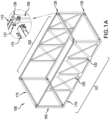
- Fig. 1A is an illustration of a representative chassis 100 that can form the support structure of a prefabricated building module.
- the chassis comprises rectangular front and rear portions 101, 102, each having a pair of vertical supports 105 and top and bottom horizontal supports 110.
- the front and rear portions 101, 102 are connected to each other with horizontal beams 115.
- the chassis can also have various other structural elements, such as posts or wall studs 120 and cross supports 125.
- Vertical supports 105 are hollow support structures (HSS) and can have a rectangular (including square), or other shape cross-section. A square cross-section is illustrated.
- HSS hollow support structures
- the various vertical supports 105, horizontal supports 110 and horizontal beams 115 are joined at each corner with a top connecting part 130 (for top chassis corners) or bottom connecting part 135 (for the bottom chassis corners).
- the connections of the horizontal supports and beams 110,115 to the connecting part 130, 135 can be made using conventional techniques.
- the vertical supports 105 and horizontal supports 110 are connected to a respective top and bottom corner connecting parts 130, 135 using welds and the horizontal beams 115 are bolted in place at a joining assembly 137 such as a butt joint, shown in more detail in Fig. 1C .
- Other connection means could be used.
- a flange can extend from a corner connecting part 130 and be connected to a horizontal beam 115 in a bolted-together lap joint, shown in more detail in Fig. 1D .
- the top and bottom connecting parts 130 are made of steel that is milled or cast into the proper configuration.
- the vertical supports are also steel.
- Vertical supports 105 can be provided, e.g., to a facility where the chassis are to be prefabricated, with the top and bottom connecting parts 130 already attached and the top and bottom ends of the assembly milled to create a flat bearing connection surface.
- Fig. 2 is an exploded view of a connection node system 200 showing a top connecting part 130 and bottom connecting part 135 along with connecting hardware including a threaded coupler nut 205 (such as one having an integral threaded aperture or a separate captive threaded nut), a diaphragm plate 210, bolt 215, shims 220 and diaphragm temporary locking bolts 225.
- a threaded coupler nut 205 such as one having an integral threaded aperture or a separate captive threaded nut
- a diaphragm plate 210 bolt 215, shims 220 and diaphragm temporary locking bolts 225.
- the diaphragm plate 210 is mounted over the top connecting part 130 and can be aligned and temporarily held in place with diaphragm locking bolts 225.
- the diaphragm plate 210 can be used to connect connecting part 130 to one or more adjacent connecting parts 130 from adjacent chasses 100 and different diaphragm plate configurations can be provided according to the number of corners at a node, such as two along the facade and four at an interior connection.
- the bottom connecting part 135 is attached to the top connecting part 130 using bolt 215.
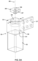
- Fig. 3A is a more detailed view of the top connecting part 130 and coupler nut 205.
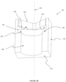
- Fig. 3B shows a cross section of the top connecting part 130 of Fig. 3A along line A-A.
- Top connecting part 130 is mounted at a top end 106 of a vertical support 105. In one configuration, the top connecting part 130 fits into the opening at the top end 106 of vertical support and can be welded or otherwise affixed into place. Other ways of joining the top connecting part 130 to the vertical support 105 can be used as well.
- the top connecting part 130 has a top surface 310.
- Vertical support 105 defines a central axis 305.
- An axial hole 325 runs from the top surface 310 to the interior of the vertical support 105.
- Axial hole 325 is configured so that bolt 215 can pass completely through the top connecting part 130 and into the interior of the vertical support 105.
- the axial hole 325 has a diameter throughout that is greater than the maximum diameter D of the head 216 of bolt 215 so the bolt 215 can be in any rotational orientation and still pass through top connecting part 130 into the vertical support 105.
- a narrower axial hole 235 could be provided if there is a need to prevent the bolt from passing into the vertical support unless it is in a correct rotational orientation.
- the top connecting part defines a bottom surface 315 within the vertical support 105.
- Joining assembly 137 can comprise one or more flanges welded or otherwise affixed to respective sides 320 of the top connecting part 130 to allow attachment of horizontal supports.
- a flat mount for a butt joint or other connection structure could be provided instead.
- the axial hole 325 has a first portion that is adjacent the top surface 310 and defines a first open area 330 into which the coupler nut 205 can be placed.
- a second portion of the axial hole defines a second open area 335 adjacent the first open area 330.
- the second open area 335 defines at least one shoulder 340 that is adjacent to the first open area 330.
- the coupler nut 205, first open area 330 and second area 335 are configured so that the coupler nut 205 when in an insertion position can pass through the first open area 330 and into the second open area 335 and can be rotated from the insertion position to a captured position where the shoulder 340 prevents removal of the coupler nut 205 through the first open area 330.
- the coupler nut 205 has a triangular, square, or other angular or curved geometric shape with a horizontal diameter that is not the same along all azimuth angles.
- the first open area 330 has substantially the same shape as the coupler nut 205 and is sized to allow the coupler nut 205 to be easily inserted without too much play.
- the second open area 335 has a circular cross section large enough to allow the coupler nut 205 to spin freely without too much play so that the aperture 206 in the coupler nut 205 remains substantially aligned with the central axis 305.
- the coupler nut is used for securing the top connecting part 130 to the bottom connecting part 135 in conjunction with the bolt 215. While the shape of the nut plate 205 and the first and second open areas 330, 335 can vary there is a balancing between increasing the surface area of the nut plate 205 that engages the shoulder 340 so that the assembly can withstand high forces involved in coupling chasses 100 together while also providing an opening large enough to allow easy access.
- the opening for the coupler nut is rotated relative to the vertical support 105 cross section, such as between 30 and 60 degrees, and in an embodiment substantially at 45 degrees.
- the final locked position of the coupler nut 205 engages a comparatively large amount of metal within the top connecting part 130 and increases the stress resistance of the total node assembly.
- Other relative rotational positions can be used for the design, including no rotation, which may make it easier to fabricate the top connecting part 130 by casting or other means.
- the coupler nut 205 can be a single integral unit with the threaded aperture 206 formed directly therein.
- the threaded aperture 206 can be provided by a captive bolt 207 formed separately from and connected to the coupler 205.
- a locking pin 345 can be inserted through a coupler locking hole 350.
- the locking pin 345 extends into the second open area 335 and functions to restrict rotation of the coupler nut 205 from its captured position.
- Fig. 3C is a cross section of the top connecting part of Fig. 3A illustrating a seated coupler nut and locking pins 345.
- two locking holes 350 are provided and positioned so that inserted locking pins 345 will bracket a corner of the coupler nut 205 and limit the amount the coupler nut can rotate so as to prevent its removal.
- locking holes 351 (not shown) can be formed in the coupler nut 205. The locking holes 350 are positioned so the locking pin 345 can pass into the locking holes 351 in the coupler nut.
- a third open area 355 can be formed beneath the second open area 335.
- the third open area 355 defines shoulders 360 at the bottom of the second open area 335 that keep the coupler nut 205 within the second open area 335 so it does not fall into the vertical support 105.
- the third open area 355 has a circular cross-section with a diameter that is less than the diameter of the second open area but greater than the diameter D of the bolt head 216.
- Fig 4A is a more detailed view of the bottom connecting part 135.
- Fig. 4B shows a cross section of the bottom connecting part 135 of Fig. 4A along line B-B.
- Bottom connecting part 135 is mounted at a bottom end 107 of a vertical support 105 (shown in phantom in Fig 4A ).
- the bottom connecting part 135 fits into the opening at the bottom end 107 of vertical support 105 and can be welded or otherwise affixed into place. Other ways of joining the bottom connecting part 135 to the vertical support 105 can be used as well.
- bottom connecting part 135 has a bore 410 that extends through it along a central axis.
- the bore 410 has an upper bore part opening 415 at a top 420 of the bottom connecting part 135 and a lower bore part opening 425 that opens at the bottom 430 of the bottom connecting part 135.
- the diameter of the bore 410 at the upper opening 415 is greater than the bolt head 216 diameter D1 and the bore diameter throughout is greater than the diameter D2 of the shank 217 of bolt 215.
- Between top and bottom of the bore 425 is a constricted area through which the bolt shank 217 but not the bolt head 216 can pass.
- the upper bore part is conical and ends at a shoulder 435 on which the head 216 of the bolt 215 can rest when the bolt 215 is inserted into the bottom connecting part.
- the lower bore part is cylindrical with a diameter large enough to allow the bolt shank 217 to pass through easily and to provide sufficient clearance to accommodate normal fabrication, assembly, and erection tolerances, but to also maximize the contact area under the head of the bolt.
- the diameter of the bore 410 from the upper opening 415 to the shoulder 435 can be constant.
- An alignment opening 440 can be provided in the bottom surface 430 and be configured to receive an alignment member 211 extending upwards from the diaphragm plate 210 during assembly of the connection node.
- the alignment opening 440 and alignment member 211 help to properly align the bottom connecting part 135 with the diaphragm plate and the top connecting part 130 in a lower chassis to which the diaphragm plate is connected.
- More than one alignment opening 440 can be provided.
- multiple alignment openings 440 can be provided to allow the same bottom connecting part 135 to mount to a diaphragm plate 210 on the left or on the right.
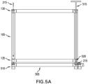
- Figs. 5A - 5C illustrate a method for joining chassis in a modular building using the connection node assembly.
- Fig. 5A shows a first chassis mounted to a foundation 505.
- the foundation 505 has mounting points 510 to which the bottom connecting parts 135 of the chassis can be joined.
- the mounting points 510 can be modified versions of a top connecting part 130 or have another configuration for receiving bolt 215.
- Fig. 5A shows an already assembled chassis 100. It should be appreciated that the vertical support 105 with the top connecting part 130 and bottom connecting part 135 already connected can be provided as a single part for use during construction of a chassis 100.
- connection node system Because of the unique configuration of the connection node system, once the chassis is aligned over the mounting points 510 it can be fixed in place without requiring a worker at the base of the chassis or inside of the chassis.
- Bolt 215 is dropped or otherwise lowered through the central bore 410 of the top connecting part 130. It passes through the hollow vertical support 105 and is captured by the bore 410 in the bottom connecting part 130.
- An elongated wrench assembly 515 can be inserted through the top connecting part 130 and lowered through the vertical support 105 until the socket 520 at the end of the wrench seats on the head of 216 of the bolt. Wrench assembly 515 is then used to tighten the bolt 215 and secure the chassis in place on the foundation 505.
- the bolt could be pre-inserted into the central bore before the chassis is lifted into place and temporarily held in place with wax, hot glue, or other similar substance.
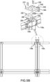
- Fig. 5B illustrates the connection of two adjacent top connecting parts 130a, 130b from horizontally adjacent chassis.
- a respective coupler nut 205 is mounted and locked into place as discussed above.
- the diaphragm plate 210 is then positioned over the top connecting parts 130a, 130b.
- One more leveling shims 220 can be added to adjust the vertical height of the diaphragm plate 210.
- the diaphragm plate and shims have bolt apertures 540, 525 through which a bolt 215 will later pass.
- one or more alignment holes 545, 530 are formed on the diaphragm plate 210 and shim 220 respectively.
- One or more corresponding alignment holes 535 are formed on the coupler nut 205.
- the alignment holes 545, 525, 535 will be aligned.
- locking bolts 225 can be inserted through holes 545, 525, 535 and serve to lock the diaphragm plate 210 and shim 220 in the proper place over the coupling nut 205.
- a temporary bolt (not shown) can also be passed through the bolt apertures 540, 525, 535. The position of a secured diaphragm plate can be surveyed to allow for repositioning of each floor to the building nominal coordinate system.
- the locking bolts 225 and temporary bolt are installed over only one top connecting part, such as 130a.
- the diaphragm plate 210 Once a portion of the diaphragm plate 210 is secured to one chassis, such as chassis 130b, by the placement of another chassis above it (see Fig. 5C ), the diaphragm plate 210 will then be held securely in place and the locking bolts 225 and temporary bolt can be removed so the locking bolts 225 do not interfere with the placement of the next chassis coming in.
- the temporary bolt also functions to close the main opening in the top connecting part to prevent water from getting into the hollow vertical support 105 if construction is occurring during wet weather.
- the bolt apertures 545 that receive the locking bolts 225 can have a diameter large enough to allow the locking bolts 225 to float in the holes to allow for misalignment. If misalignment is less of a concern, locking bolts 225 could be counterbored into the diaphragm plate 210 so removal is not needed.
- the diaphragm plate 210 can be shaped and sized according to the number and arrangement corners of a chassis to be joined at the node.
- the diaphragm plate 210 is configured so that it fully covers the top surfaces 310 of the top connecting parts 130 at the node and where the sides 550 of the diaphragm plate 210 are generally aligned with the exterior sides of the top connecting parts at that node. (See Fig. 7 discussed further below.)
- the configuration of the alignment members can vary in different diaphragm plates 210 according to where in the structure the node is located and the stacking sequence of the chassis.
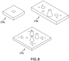
- close fit cones are placed on the diaphragm plates used near the fa ade portions of the chassis to tightly control the position of the chassis in that area.
- Diamond cones are used on diaphragm plates at the other end of the chassis to control the rotation of the chassis.
- a given diaphragm plate can have anywhere from zero to four alignment members.
- Various different diaphragm plate configurations 210a, 210b, 210c are shown in Fig. 8 .
- alignment members known to those of ordinary skill in the art can be provided to, for example, position the chassis in x/y or manage rotation of the chassis about the alignment cone.
- the alignment members can be integrally formed with the diaphragm plate or the diaphragm plate can have suitable mounting apertures and the appropriate alignment members installed separately.
- Fig. 5C shows the installation of a third chassis over one of the chassis shown in Fig. 5B .
- an upper chassis is lifted into place, its lower corners are generally aligned with the top corners of the chassis below, and then the chassis is lowered into place.
- One or more alignment members 211 on the diaphragm plate 210 mate with the corresponding alignment opening 440 at the bottom of bottom connecting part 135 to guide the upper chassis into proper alignment so that the central axis of the vertical supports 105 in the upper and lower chassis are aligned.
- Fig. 5D shows a cross section view of a fully connected node assembly at an inner node where upper and four lower chasses come together.
- a lifting plate 606 having a lifting eye 610 can be locked into the top connecting parts 130 in each corner of the chassis.
- the lifting plate has the same cross sectional shape as the coupler nut 205 and can be secured to the top connecting part in the same manner. Cables 615 can be connected to the lifting eyes for use in lifting the chassis into place. After placement, the substitute nut plate 606 can be removed.
- Fig. 6A shows one corner of a chassis 100 connected for lifting in this manner.
- bolts 215 can be inserted into the top connecting parts in the upper chassis, such as top connecting part 130c.
- the bolt 215 passes through the respective bottom connecting part 135 and engages the threaded aperture 206 in the coupling nut 205 mounted therein.
- the bolt 215 is then tightened using the elongated wrench assembly 515 (see Fig. 5 ) to couple the top and bottom connecting parts 130, 135 at each corner together.
- the bolted connection turns individual module columns connected along a vertical axis into continuous steel columns from the bottom to the top of the building.
- the bolted connect also clamps the diaphragm plate 210 between the chassis' columns and creates a tying load path laterally between all columns in the group. Once portion of the diaphragm plate 210 is clamped between one pair of chasses 100, any temporary bolts used to hold the diaphragm plate 210 in place over the top connecting parts 130 of other chassis 100 can be removed.
- disclosed node system 200 allows node horizontal and vertical chassis to be coupled to each other with only the top connecting parts 130 of each chassis 100 being exposed on the top 705 of an otherwise weather sealed chassis, such as shown in Fig. 7 which illustrates the top of four adjacent chassis prior to installation of the diaphragm plate 210.
- the nodes will define a rectangle having dimensions W by V.
- the diaphragm plate 210 which is used in this configuration will generally be a rectangle having dimensions W' by V' where W' is substantially equal to or less than W and V' is substantially equal to or less than V so that the entire top surface of the vertical supports will be covered.
- the vertical diaphragm plate could also be sitting in a recess rather than proud of the fireproofing and weatherproofing. Such a recess can be formed by using vertical supports 105 that do not extend fully to the top of the horizontal supports.
- the top of the chassis (apart from the top connecting parts) and any weather barrier formed on the top can remain undisturbed and the risk of water or other contaminants entering the interior of the chassis from the top reduced or avoided entirely.
- the entire assembly can be done from the top of each chassis. Workers are not required to access any internal portions of the chassis, thereby limiting the possibility for internal damage and reducing worker risk.
Landscapes
- Engineering & Computer Science (AREA)
- General Engineering & Computer Science (AREA)
- Architecture (AREA)
- Mechanical Engineering (AREA)
- Civil Engineering (AREA)
- Structural Engineering (AREA)
- Physics & Mathematics (AREA)
- Electromagnetism (AREA)
- Joining Of Building Structures In Genera (AREA)
- Coupling Device And Connection With Printed Circuit (AREA)
Description
- This application claims priority from
U.S. Provisional Application No. 62/971,669 filed on February 7, 2020 U.S. Patent Application No. 16/987,641 filed on August 7, 2020 U.S. Patent No. 10,907,342, issued on February 2, 2021 - The present invention relates to a connection system for use in connecting prefabricated building modules together and to a module support component having connection node assembly components formed therein.
- Many high-rise buildings are constructed using pre-fabricated modules that are stacked and joined together on-site. Each module is a generally box shaped unit with a primary chassis comprising vertical support posts and horizontal cross members joined together at corner nodes. Typically, the vertical supports in a module are hollow support structure (HSS), such as steel profiles with a square or rectangular cross-section. A prefabricated module may also be at least partially finished with internal walls, flooring, and hookups for electricity and water.
- During construction, an initial tier of modules is installed horizontally and affixed to a building foundation or previously installed substructure. Adjacent top corners of the modules are connected together with a joining plate. A second tier of modules is positioned over the first tier, aligned and positioned in place. The bottom corners of the second tier modules are then affixed to the top corners of the first tier modules.
- An advantage of using prefabricated modules is that they can be assembled inside and remotely from the construction site, reducing the amount of outdoor work that must be done at the construction site itself. Notwithstanding, job-site construction often continues in a wide variety of weather conditions. To prevent water from getting into the module assembly and damaging pre-installed components, the module, as supplied, can have an outer weatherproofing layer.
- Care must be taken during construction to avoid damaging the weatherproofing layer.
- Typically, volumetric modular buildings rely on a separate structure to provide lateral stability against horizontal loads (such as a concrete core or an external steel brace-frame). Each module is only responsible for carrying vertical loads to the tiers below through its vertical columns. Standard methods and systems for connecting prefab building modules during erection are designed to ensure vertical continuity between stacked columns and horizontal continuity between modules of the same level. Continuity is typically achieved by means of large joining plates to connect the corners of adjacent modules. These plates extend well past the vertical support members and are affixed to structures on the horizontal support beams where the connection points are accessible by the installers.
- Such use of large joining plates that extend past the vertical support members may require the weatherproofing layer to be peeled back around the corners of the module in order to expose the horizontal support beams to which the plate is connected. However, doing this also exposes a relatively large area of the module itself around the corner and can damage the weatherproofing layer. As a result, there is an increased chance of water gaining entry to the interior of the module during construction and causing damage to interior components.
- Further, conventional joining systems often require construction personnel to be positioned at the base of the module when connecting it to a module below. Limited visual and physical access to the corner connections from this position can make proper alignment difficult to achieve. Due to factors such as this, deficiencies in installation control, as well as fabrication tolerances, the installation tolerance in volumetric modular construction is normally in the 0.25 inch to one inch range and modules often need to be manually jacked into their proper alignment after they have been installed. Such misalignments exceed by far the installation tolerances for standard building facade systems which are applied to the outer walls of the building. As a result, much if not all of the facade installation operations need to be done site and this can introduce conspicuous delays to the stacking schedule.
-
JP 2001 254445 A - There is a need for an improved method and system for connecting building modules during construction that provides greater accuracy and superior load distribution characteristics along the vertical supports while providing a simplified and safer installation process that can be employed without having to disturb weatherproofing on the module.
- These and other needs are met by a connection node system as claimed in claim 1.
- The connection node system is largely integrated within the vertical supports that are used in chassis of a modular building unit. Each respective vertical support has a hollow elongated body that extends along a central axis. A first connection portion is formed at the bottom of each support and will be the top portion of the connection node system when that support is mounted on top of a lower support. The first connection portion has an axial bore through it opening into the interior of the support. The axial bore is configured so that a connecting bolt can be passed down through the interior of the support and seat on a shoulder within the bore with the bolt's shank extending out from the support.
- A second connection portion is formed on the top of each support and will be the bottom portion of the connection node system when that support is mounted beneath an upper support. The second connection portion comprises an axial hole extending to the interior of the support. The axial hole has a diameter throughout greater than the head diameter of the connecting bolts to permit a bolt and associated drive socket to be fed through the second connection portion and through the support's interior allowing the bolt to engage the bore in the first connection portion. The axial hole should also be large enough to allow a tool for tightening the bolt to be passed through. The axial hole has an internally facing shoulder and is configured so a coupler nut in an insertion position can be placed into the axial hole along the axis and then rotated axially to a captured position where the shoulder blocks axial motion of the coupler towards the second end. The coupler nut has a threaded aperture to receive the shank of the bolt extending out from the first connection portion of an upper support.
- The supports can be steel hollow support structures that can have a rectangular (including square) or other cross-sectional shape. The coupling nut can have the same cross-section shape as the support or a different shape. The axial hole has a first open area adjacent to the end of the support. The first open area can have the same cross-section shape as the coupling nut and is large enough to allow the nut to pass through. A second open area is axially inward and adjacent to the first open area. The second open area can have a circular cross-section with a diameter substantially the same as the maximum diameter of the first open area. The larger second open area defines inward facing shoulders adjacent to the first open area which prevents the coupler nut from being removed when rotated to a captured position. A third open area formed inward from the second area nut keeps the coupler nut from passing inward beyond the second area. The first open area can have the same shape or different shape as the support cross-section, such as square, and can be rotated thereto so that sides defining the first open area are not parallel to the sides of the support.
- One or more locking holes can be provided in the end surface of the second connecting part and that extend through to the second open area. The locking holes are positioned so that when a locking pin is inserted into the locking hole, the locking pin restricts rotation of a coupler in the captured position within the second open area.
- A diaphragm plate can be provided to connect the tops of horizontally adjacent vertical supports. The diaphragm plate has a plurality of bolt apertures that are positioned to align with the threaded apertures in coupler nuts mounted in the second connection portions of the adjacent supports. The diaphragm plate can also have vertically extending alignment members (such as circular or diamond profile pins or cones) that mate with corresponding alignment features in the first connecting portion of a vertical support being lowered therein.
- Alignment holes can also be formed in the diaphragm plate and the second connecting portion and/or the coupler nut. The alignment holes are positioned so that when the coupler is in the captured position in the second connection part, the diaphragm plate can be positioned over the second connection part with the diaphragm alignment hole and coupler alignment hole axially aligned and the bolt aperture axially aligned with the axial hole in the second connector part. Locking bolts placed through the diaphragm alignment holes and into the coupler alignment holes can be used to temporarily hold the diaphragm plate in alignment over one vertical support while the vertical support from an upper module is lowered over another portion of the diaphragm. A bolt can also be temporarily inserted through the diaphragm plate into the coupler nut. Once the diaphragm is clamped in place under that other vertical support, the locking bolts and diaphragm plate bolt can be removed.
- A lifting plate with the same basic shape as the coupler nut can also be provided. Instead of a threaded aperture, the lifting plate has a lifting eye. The lifting plate can be mounted in the second portion of the vertical supports (e.g., at the top) in the same manner as a coupler nut and the lifting eye used as a cable connection point for hoisting the module into place. When the module is correctly placed, the lifting plate can be removed.
- Advantageously, the internal bolting configuration allows building modules to be connected without having to disturb existing weatherproofing. The diaphragm plate can also be reduced in size so that it only covers the tops of the adjacent vertical supports, reducing weight and material cost. The connection node system, as disclosed, allows a node of eight module corners (where four upper and four lower modules come together) to be securely joined together using only four bolts and an appropriately configured diaphragm plate. Because a connecting bolt is inserted through the top of the vertical support on an upper module and tightened using an elongated wrench assembly operated from above the upper, module workers need to spend less time working at the bottom of a module thereby increasing worker safety.
- The bolted connection can resist tension as required by various building codes, even if the connection remains in compression during its use in all load cases. The bolt can be pre-tensioned during construction during the stacking procedure. This bolted connection turns individual module columns into continuous steel columns from the bottom to the top of the building. When rectangular modules are stacked, neighboring corner columns sit side by side in configurations of two (at the faade) or four (internally). At the corners and irregular shaped areas of a building there may also be configurations of one (i.e. a single column) or three. Differently shaped modules, such as hexagons, would have more possible configurations. The diaphragm plate placed on top of columns connects side by side neighboring columns together during stacking. The column bolts from the modules above pass through holes in the diaphragm plate and the diaphragm plate operates to create a tying load path laterally between all columns in the group.

- The chassis components can be assembled at the offsite module assembly facility by bolting the components together. This allows for efficient transport to the module assembly facility by transporting the pre-assembled frames and beams in a flat pack configuration rather than a volumetric configuration. This enables the industry best practice of not "shipping air".
- The simple bolted construction at the offsite assembly facility eliminates any need for welded joints, thus reducing the time to assemble and inspect the components, and reducing the labor content overall. The lack of welding at the assembly facility and the construction site reduces the level of skill required to erect the building and lowers the overall cost of labor and inspection.
- The bolted connections provide for significantly tighter control of build tolerances, allowing for stacking with a curtain wall faade pre-installed on the modules. Components can be machined for tight tolerance assembly and then assembled and inspected to tighter tolerances without incurring significant cost.
- The use of standardized components allows for efficiencies of scale in their production, such as development of tooling for the rapid setup of CNC machinery to perform the final machining of a cross beam, including the location of the bolt holes.
- Further features and advantages of the invention, as well as structure and operation of various aspects of the methods and systems of the invention the implementations are disclosed in detail below with references to the accompanying drawings, in which:
-
Fig. 1A is an illustration of a representative chassis that can form the support structure of a prefabricated building module; -
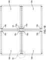
Fig. 1B is a diagram of four chassis stacked vertically and horizontally in a modular building configuration; -
Figs. 1C and 1D are views of different joining assemblies to attach the node to a horizontal support; -
Fig. 2 is an exploded view of a connection node system according to aspects of the invention; -
Fig. 3A is a detailed view of the top connecting part and coupler nut of the node connection system shown inFig. 2 ; -
Fig. 3B is a cross section of the top connecting part ofFig. 3A along line A-A; -
Fig. 3C is a cross section of the top connecting part ofFig. 3A with a coupler nut; -
Fig 4A is a detailed view of the bottom connecting part of the node connection system shown inFig. 2 ; -
Fig. 4B is a cross section of the bottom connecting part ofFig. 4A along line B-B; -
Figs. 5A - 5C illustrate a method for joining chassis in a modular building using the connection node assembly ofFig. 2 ; -
Fig. 5D shows a cross section view of a fully connected node assembly at an inner node where upper and four lower chasses come together. -
Figs. 6A - 6B illustrate use of a temporary nut plate in a top connecting part to provide lifting points of a chassis; -
Fig. 7 illustrates the top of four adjacent chassis prior to installation of the diaphragm plate thereon; and -
Fig. 8 illustrates various different diaphragm plate configurations. -
Fig. 1A is an illustration of arepresentative chassis 100 that can form the support structure of a prefabricated building module. The chassis comprises rectangular front andrear portions vertical supports 105 and top and bottom horizontal supports 110. The front andrear portions horizontal beams 115. The chassis can also have various other structural elements, such as posts orwall studs 120 and cross supports 125. Vertical supports 105 are hollow support structures (HSS) and can have a rectangular (including square), or other shape cross-section. A square cross-section is illustrated. - The various
vertical supports 105,horizontal supports 110 andhorizontal beams 115 are joined at each corner with a top connecting part 130 (for top chassis corners) or bottom connecting part 135 (for the bottom chassis corners). The connections of the horizontal supports and beams 110,115 to the connectingpart vertical supports 105 andhorizontal supports 110 are connected to a respective top and bottomcorner connecting parts horizontal beams 115 are bolted in place at a joiningassembly 137 such as a butt joint, shown in more detail inFig. 1C . Other connection means could be used. Instead of a butt joint, a flange can extend from acorner connecting part 130 and be connected to ahorizontal beam 115 in a bolted-together lap joint, shown in more detail inFig. 1D . - In one configuration, the top and
bottom connecting parts 130 are made of steel that is milled or cast into the proper configuration. The vertical supports are also steel. Vertical supports 105 can be provided, e.g., to a facility where the chassis are to be prefabricated, with the top andbottom connecting parts 130 already attached and the top and bottom ends of the assembly milled to create a flat bearing connection surface. -
Fig. 1B is a diagram showing a side view of fourchassis nodes -
Fig. 2 is an exploded view of aconnection node system 200 showing a top connectingpart 130 andbottom connecting part 135 along with connecting hardware including a threaded coupler nut 205 (such as one having an integral threaded aperture or a separate captive threaded nut), adiaphragm plate 210,bolt 215,shims 220 and diaphragmtemporary locking bolts 225. As discussed in more detail below, during construction the coupler nut is placed into and locked within connectingpart 130. Thediaphragm plate 210 is mounted over the top connectingpart 130 and can be aligned and temporarily held in place withdiaphragm locking bolts 225. Thediaphragm plate 210 can be used to connect connectingpart 130 to one or more adjacent connectingparts 130 fromadjacent chasses 100 and different diaphragm plate configurations can be provided according to the number of corners at a node, such as two along the facade and four at an interior connection. Thebottom connecting part 135 is attached to thetop connecting part 130 usingbolt 215. -
Fig. 3A is a more detailed view of the top connectingpart 130 andcoupler nut 205.Fig. 3B shows a cross section of the top connectingpart 130 ofFig. 3A along line A-A. Top connectingpart 130 is mounted at atop end 106 of avertical support 105. In one configuration, thetop connecting part 130 fits into the opening at thetop end 106 of vertical support and can be welded or otherwise affixed into place. Other ways of joining thetop connecting part 130 to thevertical support 105 can be used as well. - The
top connecting part 130 has atop surface 310.Vertical support 105 defines acentral axis 305. Anaxial hole 325 runs from thetop surface 310 to the interior of thevertical support 105.Axial hole 325 is configured so thatbolt 215 can pass completely through thetop connecting part 130 and into the interior of thevertical support 105. In a particular embodiment, theaxial hole 325 has a diameter throughout that is greater than the maximum diameter D of thehead 216 ofbolt 215 so thebolt 215 can be in any rotational orientation and still pass through top connectingpart 130 into thevertical support 105. A narrower axial hole 235 could be provided if there is a need to prevent the bolt from passing into the vertical support unless it is in a correct rotational orientation. - The top connecting part defines a
bottom surface 315 within thevertical support 105. Depending on the configuration of the top connecting could merge into the inner side walls of thevertical support 105 so that thebottom surface 315 is minimized (or absent entirely). Joiningassembly 137 can comprise one or more flanges welded or otherwise affixed torespective sides 320 of the top connectingpart 130 to allow attachment of horizontal supports. A flat mount for a butt joint or other connection structure could be provided instead. - The
axial hole 325 has a first portion that is adjacent thetop surface 310 and defines a firstopen area 330 into which thecoupler nut 205 can be placed. A second portion of the axial hole defines a secondopen area 335 adjacent the firstopen area 330. The secondopen area 335 defines at least oneshoulder 340 that is adjacent to the firstopen area 330. Thecoupler nut 205, firstopen area 330 andsecond area 335 are configured so that thecoupler nut 205 when in an insertion position can pass through the firstopen area 330 and into the secondopen area 335 and can be rotated from the insertion position to a captured position where theshoulder 340 prevents removal of thecoupler nut 205 through the firstopen area 330. - The
coupler nut 205 has a triangular, square, or other angular or curved geometric shape with a horizontal diameter that is not the same along all azimuth angles. In the illustrated embodiment, the firstopen area 330 has substantially the same shape as thecoupler nut 205 and is sized to allow thecoupler nut 205 to be easily inserted without too much play. The secondopen area 335 has a circular cross section large enough to allow thecoupler nut 205 to spin freely without too much play so that theaperture 206 in thecoupler nut 205 remains substantially aligned with thecentral axis 305. - As discussed further below, the coupler nut is used for securing the
top connecting part 130 to thebottom connecting part 135 in conjunction with thebolt 215. While the shape of thenut plate 205 and the first and secondopen areas nut plate 205 that engages theshoulder 340 so that the assembly can withstand high forces involved incoupling chasses 100 together while also providing an opening large enough to allow easy access. - In a configuration where the
vertical support 105 and coupler nut are both rectangular, the opening for the coupler nut is rotated relative to thevertical support 105 cross section, such as between 30 and 60 degrees, and in an embodiment substantially at 45 degrees. In this configuration, the final locked position of thecoupler nut 205 engages a comparatively large amount of metal within thetop connecting part 130 and increases the stress resistance of the total node assembly. Other relative rotational positions can be used for the design, including no rotation, which may make it easier to fabricate thetop connecting part 130 by casting or other means. - Different shapes of the
coupler nut 205, firstopen area 330, and secondopen area 335 could be used as long as capture of thecoupler nut 205 in the secondopen area 335 can be achieved as discussed herein. In addition, thecoupler nut 205 can be a single integral unit with the threadedaperture 206 formed directly therein. Alternatively, the threadedaperture 206 can be provided by acaptive bolt 207 formed separately from and connected to thecoupler 205. - To retain the
coupler nut 205 in the captured position, alocking pin 345 can be inserted through acoupler locking hole 350. Thelocking pin 345 extends into the secondopen area 335 and functions to restrict rotation of thecoupler nut 205 from its captured position.Fig. 3C is a cross section of the top connecting part ofFig. 3A illustrating a seated coupler nut and locking pins 345. In the embodiment shown inFig. 3C , two lockingholes 350 are provided and positioned so that inserted lockingpins 345 will bracket a corner of thecoupler nut 205 and limit the amount the coupler nut can rotate so as to prevent its removal. In an alternative embodiment, locking holes 351 (not shown) can be formed in thecoupler nut 205. The locking holes 350 are positioned so the lockingpin 345 can pass into the locking holes 351 in the coupler nut. - Returning to
Fig. 3B , a thirdopen area 355 can be formed beneath the secondopen area 335. The thirdopen area 355 definesshoulders 360 at the bottom of the secondopen area 335 that keep thecoupler nut 205 within the secondopen area 335 so it does not fall into thevertical support 105. In the illustrated embodiment, the thirdopen area 355 has a circular cross-section with a diameter that is less than the diameter of the second open area but greater than the diameter D of thebolt head 216. -
Fig 4A is a more detailed view of thebottom connecting part 135.Fig. 4B shows a cross section of thebottom connecting part 135 ofFig. 4A along line B-B.Bottom connecting part 135 is mounted at abottom end 107 of a vertical support 105 (shown in phantom inFig 4A ). In one configuration, thebottom connecting part 135 fits into the opening at thebottom end 107 ofvertical support 105 and can be welded or otherwise affixed into place. Other ways of joining thebottom connecting part 135 to thevertical support 105 can be used as well. - With reference to
Figs. 4A and4B ,bottom connecting part 135 has abore 410 that extends through it along a central axis. Thebore 410 has an upperbore part opening 415 at a top 420 of thebottom connecting part 135 and a lowerbore part opening 425 that opens at the bottom 430 of thebottom connecting part 135. The diameter of thebore 410 at theupper opening 415 is greater than thebolt head 216 diameter D1 and the bore diameter throughout is greater than the diameter D2 of theshank 217 ofbolt 215. Between top and bottom of thebore 425 is a constricted area through which thebolt shank 217 but not thebolt head 216 can pass. - In the illustrated embodiment, the upper bore part is conical and ends at a
shoulder 435 on which thehead 216 of thebolt 215 can rest when thebolt 215 is inserted into the bottom connecting part. The lower bore part is cylindrical with a diameter large enough to allow thebolt shank 217 to pass through easily and to provide sufficient clearance to accommodate normal fabrication, assembly, and erection tolerances, but to also maximize the contact area under the head of the bolt. Various other configurations of the upper andlower bore parts bore 410 from theupper opening 415 to theshoulder 435 can be constant. - An
alignment opening 440 can be provided in thebottom surface 430 and be configured to receive analignment member 211 extending upwards from thediaphragm plate 210 during assembly of the connection node. Thealignment opening 440 andalignment member 211 help to properly align thebottom connecting part 135 with the diaphragm plate and thetop connecting part 130 in a lower chassis to which the diaphragm plate is connected. More than onealignment opening 440 can be provided. For example,multiple alignment openings 440 can be provided to allow the samebottom connecting part 135 to mount to adiaphragm plate 210 on the left or on the right. -
Figs. 5A - 5C illustrate a method for joining chassis in a modular building using the connection node assembly.Fig. 5A shows a first chassis mounted to afoundation 505. Thefoundation 505 has mountingpoints 510 to which thebottom connecting parts 135 of the chassis can be joined. The mounting points 510 can be modified versions of a top connectingpart 130 or have another configuration for receivingbolt 215.Fig. 5A shows an already assembledchassis 100. It should be appreciated that thevertical support 105 with thetop connecting part 130 andbottom connecting part 135 already connected can be provided as a single part for use during construction of achassis 100. - Because of the unique configuration of the connection node system, once the chassis is aligned over the mounting
points 510 it can be fixed in place without requiring a worker at the base of the chassis or inside of the chassis.Bolt 215 is dropped or otherwise lowered through thecentral bore 410 of the top connectingpart 130. It passes through the hollowvertical support 105 and is captured by thebore 410 in thebottom connecting part 130. Anelongated wrench assembly 515 can be inserted through thetop connecting part 130 and lowered through thevertical support 105 until thesocket 520 at the end of the wrench seats on the head of 216 of the bolt.Wrench assembly 515 is then used to tighten thebolt 215 and secure the chassis in place on thefoundation 505. In an alternative embodiment, the bolt could be pre-inserted into the central bore before the chassis is lifted into place and temporarily held in place with wax, hot glue, or other similar substance. -
Fig. 5B illustrates the connection of two adjacenttop connecting parts respective coupler nut 205 is mounted and locked into place as discussed above. Thediaphragm plate 210 is then positioned over the top connectingparts diaphragm plate 210. The diaphragm plate and shims havebolt apertures bolt 215 will later pass. To help align theaperture aperture 206 in thecoupler nut 205, one or more alignment holes 545, 530 are formed on thediaphragm plate 210 and shim 220 respectively. One or more corresponding alignment holes 535 are formed on thecoupler nut 205. When thecoupler nut 205 is locked in place and theshim 220 anddiaphragm plate 210 are properly positioned, the alignment holes 545, 525, 535 will be aligned. At thispoint locking bolts 225 can be inserted throughholes diaphragm plate 210 andshim 220 in the proper place over thecoupling nut 205. A temporary bolt (not shown) can also be passed through thebolt apertures - According to a particular method, when joining two adjacent
top connecting parts bolts 225 and temporary bolt are installed over only one top connecting part, such as 130a. Once a portion of thediaphragm plate 210 is secured to one chassis, such aschassis 130b, by the placement of another chassis above it (seeFig. 5C ), thediaphragm plate 210 will then be held securely in place and the lockingbolts 225 and temporary bolt can be removed so the lockingbolts 225 do not interfere with the placement of the next chassis coming in. The temporary bolt also functions to close the main opening in the top connecting part to prevent water from getting into the hollowvertical support 105 if construction is occurring during wet weather. Thebolt apertures 545 that receive the lockingbolts 225 can have a diameter large enough to allow the lockingbolts 225 to float in the holes to allow for misalignment. If misalignment is less of a concern, lockingbolts 225 could be counterbored into thediaphragm plate 210 so removal is not needed. - The
diaphragm plate 210 can be shaped and sized according to the number and arrangement corners of a chassis to be joined at the node. In an embodiment, thediaphragm plate 210 is configured so that it fully covers thetop surfaces 310 of thetop connecting parts 130 at the node and where thesides 550 of thediaphragm plate 210 are generally aligned with the exterior sides of the top connecting parts at that node. (SeeFig. 7 discussed further below.) - The configuration of the alignment members can vary in
different diaphragm plates 210 according to where in the structure the node is located and the stacking sequence of the chassis. In an embodiment, close fit cones are placed on the diaphragm plates used near the faade portions of the chassis to tightly control the position of the chassis in that area. Diamond cones are used on diaphragm plates at the other end of the chassis to control the rotation of the chassis. Depending on the stacking sequence and position, a given diaphragm plate can have anywhere from zero to four alignment members. Various differentdiaphragm plate configurations Fig. 8 . Differently configured alignment members known to those of ordinary skill in the art can be provided to, for example, position the chassis in x/y or manage rotation of the chassis about the alignment cone. The alignment members can be integrally formed with the diaphragm plate or the diaphragm plate can have suitable mounting apertures and the appropriate alignment members installed separately. -
Fig. 5C shows the installation of a third chassis over one of the chassis shown inFig. 5B . With reference toFig. 5C andFig. 2 , an upper chassis is lifted into place, its lower corners are generally aligned with the top corners of the chassis below, and then the chassis is lowered into place. One ormore alignment members 211 on thediaphragm plate 210 mate with the corresponding alignment opening 440 at the bottom ofbottom connecting part 135 to guide the upper chassis into proper alignment so that the central axis of thevertical supports 105 in the upper and lower chassis are aligned.Fig. 5D shows a cross section view of a fully connected node assembly at an inner node where upper and four lower chasses come together. - According to a further feature, and as shown in
Figs. 6A and6B , alifting plate 606 having a liftingeye 610 can be locked into thetop connecting parts 130 in each corner of the chassis. The lifting plate has the same cross sectional shape as thecoupler nut 205 and can be secured to the top connecting part in the same manner.Cables 615 can be connected to the lifting eyes for use in lifting the chassis into place. After placement, thesubstitute nut plate 606 can be removed.Fig. 6A shows one corner of achassis 100 connected for lifting in this manner. - Returning to
Fig. 5C , after the upper and lower chassis are aligned,bolts 215 can be inserted into the top connecting parts in the upper chassis, such as top connectingpart 130c. Thebolt 215 passes through the respectivebottom connecting part 135 and engages the threadedaperture 206 in thecoupling nut 205 mounted therein. Thebolt 215 is then tightened using the elongated wrench assembly 515 (seeFig. 5 ) to couple the top andbottom connecting parts diaphragm plate 210 between the chassis' columns and creates a tying load path laterally between all columns in the group. Once portion of thediaphragm plate 210 is clamped between one pair ofchasses 100, any temporary bolts used to hold thediaphragm plate 210 in place over the top connectingparts 130 ofother chassis 100 can be removed. - Advantageously, disclosed
node system 200 allows node horizontal and vertical chassis to be coupled to each other with only thetop connecting parts 130 of eachchassis 100 being exposed on the top 705 of an otherwise weather sealed chassis, such as shown inFig. 7 which illustrates the top of four adjacent chassis prior to installation of thediaphragm plate 210. Once multiple modules are stacked, the nodes will define a rectangle having dimensions W by V. Thediaphragm plate 210 which is used in this configuration will generally be a rectangle having dimensions W' by V' where W' is substantially equal to or less than W and V' is substantially equal to or less than V so that the entire top surface of the vertical supports will be covered. The vertical diaphragm plate could also be sitting in a recess rather than proud of the fireproofing and weatherproofing. Such a recess can be formed by usingvertical supports 105 that do not extend fully to the top of the horizontal supports. - Advantageously, the top of the chassis (apart from the top connecting parts) and any weather barrier formed on the top can remain undisturbed and the risk of water or other contaminants entering the interior of the chassis from the top reduced or avoided entirely.
- In addition, the entire assembly can be done from the top of each chassis. Workers are not required to access any internal portions of the chassis, thereby limiting the possibility for internal damage and reducing worker risk.
- Various aspects, embodiments, and examples of the invention have been disclosed and described herein. Modifications, additions and alterations may be made by one skilled in the art without departing from the scope of the invention as defined in the appended claims.
Claims (15)
- A connection system for use in connecting prefabricated building modules together, the system comprising:a bolt (215) having a head (216) with a head diameter and a shank (217) with a shank diameter;a coupler (205) having a threaded aperture therein sized to threadedly receive the shank of the bolt; andfirst and second support elements (105);each respective support element (105) comprising:an elongated hollow body having a central axis (305), first and second ends with respective first and second outer surfaces substantially perpendicular to the central axis, an interior, a first connection part (135) at the first end and a second connection part (130) at the second end;the first connection part (135) having a bore (410) therein along the central axis with a first opening (415) adjacent the interior and having a first diameter, a second opening (425) in the first outer surface and having a second diameter less than the first diameter, and a shoulder (435) within the bore between the first opening and second opening, the head diameter of the bolt being less than the first diameter and greater than the second diameter and the shank diameter of the bolt being less than the second diameter, wherein the bolt can pass partially through the bore with the shank extending therefrom; andthe second connection part (130) having an axial hole (325) therein running from the second outer surface to the interior and having a diameter throughout greater than the head diameter of the bolt and an inward facing shoulder (340) therein, the axial hole configured to allow the coupler (205) in an insertion position to be moved from outside of the body adjacent the second end through the axial hole past the shoulder and to permit rotation of the coupler within the axial hole from the insertion position to a captured position where the shoulder blocks motion of the coupler towards the second end;wherein the first connection part (135-1) of the first support element (101) can be axially connected to the second connection part (130) of the second support element (105) by inserting the bolt (215) into the bore in the first support element (410) via the second connection part of the first support element (130) and rotating the bolt so the shank engages the threaded aperture in the coupler (205) when the coupler is mounted in the captured position within the axial hole of the second connection part of the second support element (325).
- The connection system of claim 1, for each respective support element the axial hole (325) in the second part defining a first open area (330) adjacent the second end into which the coupler can be placed when in the insertion position, and a second open area (335) adjacent the first open area, the second open area configured to permit rotation of the coupler when in the second open area from the insertion position to the captured position and wherein when in the captured position the shoulder (340) prevents removal of the coupler from the second open area.
- The connection system of claim 2, the coupler (205) having a rectangular cross-section,for each respective support element (105) the elongated body having four outer sides substantially parallel to the central axis and defining a rectangular circumference,the first open area having four inner sides substantially parallel to the central axis and defining a rectangular open area into which the coupler can pass;the rectangular open area rotated relative to the rectangular circumference by between 15 to 30 degrees.
- The connection system of any of claims 1-3, for each respective support element (105) the second connection part (130) further comprising a first coupler locking hole (350) in the respective top surface and extending through to the second open area, wherein when a first locking pin (345) is inserted into the first coupler locking hole, the first locking pin restricts rotation of the coupler when the coupler is in the captured position within the second open area.
- The connection system of claim 1, for each respective support element (105) the first connecting part further comprising at least one alignment opening (440) in the first connecting part bottom surface and configured to receive an alignment member (211) extending upwards from a generally planar diaphragm plate (210) when the first connecting part is lowered onto the diaphragm plate.
- The connection system of claim 5, further comprising the diaphragm plate;the diaphragm plate (210) having a top surface with the alignment member (211) extending upwards therefrom and having a bolt aperture (540) passing from the respective top surface to a bottom surface of the diaphragm plate and having a diameter greater than the shank diameter;wherein the diaphragm plate can be positioned between the first connection part of the first support element and the second connection part of the second support element with the alignment member engaged in the alignment opening and the bolt aperture axially aligned with the central axis of the first vertical support and the central axis of the second vertical support.
- The connection system of claim 5, the diaphragm plate (210) having a diaphragm alignment hole (545) formed therein, the coupler having a coupler alignment hole (535) formed therein,
the diaphragm alignment hole and coupler alignment hole positioned on the diaphragm plate and coupler respectively so that when the coupler is in the captured position in the second connection part of a respective support element the diaphragm plate can be positioned over the second connection part with the diaphragm alignment hole and coupler alignment hole axially aligned and the bolt aperture axially aligned with the axial hole in the second connector part. - A building module having a bottom, a top, and a plurality of connection systems as recited in any of claims 1-7, the support element of each connection system being vertically oriented and extending from the bottom of the module to the top of the module with the first connection part at the bottom of the module and the second connection part at the top of the module.
- A method for assembling a structure comprising the steps of:providing a plurality of prefabricated building modules, each module having a hollow vertical support (105) wherein vertically adjacent supports are joinable using a bolt (215) having a threaded shank (217) with a shank diameter and a head (216) with a head diameter greater than the shank diameter,each vertical support (105) having a respective central axis (305), top and bottom ends, and comprising (i) a first connection part (135) at the bottom end of the respective vertical support and having a bore (410) therein along the central axis and having a first opening (415) with a diameter greater than the bolt head diameter and adjacent an interior of the respective vertical support, and a second opening (425) adjacent the bottom of the respective vertical support and having a diameter greater than the shank diameter but less than the bolt diameter, wherein the bolt can pass partially through the bore, and (ii) a second connection part (130) at the vertical support top end, the second connecting part having an axial hole (325) running from a top surface to a bottom surface and having a diameter throughout greater than the head diameter of the bolt and a downward facing shoulder (340) therein, the axial hole configured to permit rotation of a coupler (205) around the central axis from an insertion position to a captured position wherein the shoulder blocks removal of the coupler;placing a first lower module;securing a first coupler in the captured position within the axial hole in the second connection part of the vertical support of the first lower module, the first coupler having a threaded aperture therein;placing a first upper module above the first lower module so that the vertical support of the first lower module and the vertical support of first upper module are substantially axially aligned;inserting a first bolt through the second connection part of the vertical support of the first upper module and into the bore of the first connection part of the vertical support of the first upper module, wherein the shank of the bolt extends from the first connection part to engage the first coupler threaded aperture; andtightening the first bolt with a wrench assembly (515) inserted through the second connection part of the vertical support of the first upper module.
- The method of claim 9, further comprising the steps of, prior to placing the first upper module:placing a second lower module horizontally next to the first lower module so that the respective vertical supports of the first and second lower modules are adjacent;securing a second coupler in the captured position within the axial hole in the second connection part of the vertical support of the second lower module, the second coupler having a threaded aperture therein;placing a diaphragm plate (210) over the second connection parts of the vertical supports of the first and second lower module; the diaphragm plate having a first bolt aperture (540) aligned with the threaded aperture of the first coupler and a second bolt aperture (540) aligned with the threaded aperture of the second coupler.
- The method of claim 10, further comprising the step of, prior to placing the first upper module, temporarily securing the diaphragm plate to one of (a) the second coupler and (b) in the second connection part of the vertical support of the second lower module.
- The method of claim 11, wherein the diaphragm plate (210) and coupler (205) have respective alignment holes (545, 535) therein, the step of temporarily securing the diaphragm plate comprising inserting a locking bolt (225) through the diaphragm plate alignment hole and into the coupler alignment hole.
- The method of any of claims 10-12 the step of temporarily securing the diaphragm plate further comprising the steps of:prior to placing the first upper module inserting a second bolt through the second bolt aperture and into the threaded aperture of the second coupler; andremoving the second bolt after placing the first upper module.
- The method of claim 12, the diaphragm plate (210) having an alignment member (211) extending upwards therefrom, the first connecting part at the bottom end of the vertical support of the first upper module having a bottom surface with an alignment opening (440) therein;
the step of placing the first upper module comprising lowering the first upper module onto the first lower module so the alignment member engages the alignment opening. - The method of claim 9, further comprising the step of:providing a lifting plate (606) having lifting eye (610) extending upwards therefrom;securing the lifting plate in the captured position within the axial hole in the second connection part of the vertical support of the first upper module;lifting the first upper module using a cable connected to the lifting eye; andremoving the lifting plate after the step of placing the first upper module.
Applications Claiming Priority (3)
| Application Number | Priority Date | Filing Date | Title |
|---|---|---|---|
| US202062971669P | 2020-02-07 | 2020-02-07 | |
| US16/987,641 US10907342B1 (en) | 2020-02-07 | 2020-08-07 | Connection node for modular building structures |
| PCT/US2021/070116 WO2021159141A1 (en) | 2020-02-07 | 2021-02-03 | Connection node for modular building structures |
Publications (3)
| Publication Number | Publication Date |
|---|---|
| EP4100583A1 EP4100583A1 (en) | 2022-12-14 |
| EP4100583A4 EP4100583A4 (en) | 2024-03-13 |
| EP4100583B1 true EP4100583B1 (en) | 2025-05-28 |
Family
ID=74260648
Family Applications (1)
| Application Number | Title | Priority Date | Filing Date |
|---|---|---|---|
| EP21750534.6A Active EP4100583B1 (en) | 2020-02-07 | 2021-02-03 | Connection node for modular building structures |
Country Status (5)
| Country | Link |
|---|---|
| US (1) | US10907342B1 (en) |
| EP (1) | EP4100583B1 (en) |
| AU (2) | AU2021217231B2 (en) |
| CA (1) | CA3166260C (en) |
| WO (1) | WO2021159141A1 (en) |
Families Citing this family (22)
| Publication number | Priority date | Publication date | Assignee | Title |
|---|---|---|---|---|
| KR102526136B1 (en) * | 2013-02-22 | 2023-04-26 | 지-모듈러 홀딩, 인크. | Modular building units, and methods of constructing and transporting same |
| EP4733517A3 (en) * | 2015-08-14 | 2026-05-13 | Z-Modular Holding, Inc | Connector for a modular building |
| US10233953B1 (en) * | 2017-04-13 | 2019-03-19 | The United States Of America As Represented By The Secretary Of The Navy | Connector for non-cylindrical composite tubing and methods for making the same |
| EP3978711B1 (en) * | 2019-05-29 | 2025-09-03 | IMAC Engineering Co., Ltd. | Plant facility construction method and plant facility |
| US12312799B2 (en) * | 2019-08-06 | 2025-05-27 | Jgc Corporation | Module for separate conveyance, structure for plant, and method of constructing structure for plant |
| KR102286493B1 (en) * | 2020-02-21 | 2021-08-05 | 김승일 | Beam Assembly |
| CN113279482B (en) * | 2021-04-13 | 2022-03-08 | 青岛理工大学 | Module building integrated connecting device and mounting method |
| BR112023025411A2 (en) * | 2021-06-04 | 2024-02-20 | Andrew Tuohey | DATA PROCESSING CENTER, METHOD OF ASSEMBLY A DATA PROCESSING CENTER AND PREFABRICATED EQUIPMENT MODULE |
| US12338617B2 (en) | 2021-07-02 | 2025-06-24 | Blokable, Llc | Resilient connector and methods of use of same |
| CZ309779B6 (en) * | 2021-09-02 | 2023-10-04 | Univerzita Karlova | A modular structural coupling for joining structural profiles into load-bearing skeletons of various shapes |
| CN114045939B (en) * | 2021-11-11 | 2024-05-17 | 重庆大学 | Quick splice node structure between box that is fit for concatenation full fitment room unit |
| US20260125899A1 (en) * | 2022-02-28 | 2026-05-07 | Quality Electrical Systems, Inc. | End wall system for portable electrical buildings |
| US12247391B2 (en) * | 2022-04-24 | 2025-03-11 | ANC Capital Inc. | Concrete void form and method of modular construction therewith |
| USD1106508S1 (en) * | 2022-06-14 | 2025-12-16 | Spacecube IP Pty Ltd | Construction element |
| GB202208827D0 (en) * | 2022-06-15 | 2022-07-27 | City Univ Of London | Connector |
| US12490686B2 (en) | 2022-08-30 | 2025-12-09 | Toan Phan | Bracket system for attaching a cantilevered pergola to a roof rafter |
| US11566415B1 (en) * | 2022-08-30 | 2023-01-31 | Toan Phan | Bracket system for attaching a cantilevered pergola to a roof rafter |
| CN115450326B (en) * | 2022-10-27 | 2024-04-26 | 中南大学 | Pushing sliding block type detachable module steel structure node and construction method thereof |
| US20250270804A1 (en) * | 2024-02-22 | 2025-08-28 | Onx, Inc. | Method and arrangement for coupling a foundation structure and a vertical precast structure |
| WO2025196737A1 (en) * | 2024-03-22 | 2025-09-25 | Domingos Da Silva Teixeira S.A. | Connection system of a building system and respective assembly method |
| CN118242351B (en) * | 2024-05-27 | 2024-07-19 | 四川博科斯电力科技有限公司 | Bolt displacement monitoring device of flange spliced modular composite material electric pole |
| CN119686453B (en) * | 2025-01-03 | 2025-10-17 | 中国能源建设集团山西省电力勘测设计院有限公司 | Self-locking type connecting node for plug pins of modularized building structure |
Family Cites Families (19)
| Publication number | Priority date | Publication date | Assignee | Title |
|---|---|---|---|---|
| US3563581A (en) * | 1969-09-29 | 1971-02-16 | Michael Sommerstein | Joint for structural assemblies |
| ZA761548B (en) * | 1976-03-12 | 1977-10-26 | Serbert Ind Ltd | Connector |
| DE2704954A1 (en) * | 1977-02-07 | 1978-08-10 | Otto Prof Dipl Ing D Jungbluth | SPATIAL STRUCTURAL STRUCTURE OF BARS AND NODE BODIES |
| DE3784083D1 (en) * | 1986-03-13 | 1993-03-25 | Braden Christopher Godden | SPECIALTY CONNECTORS. |
| US4758111A (en) * | 1986-11-21 | 1988-07-19 | Michael Vitta | Protective enclosures |
| US5860258A (en) | 1997-06-09 | 1999-01-19 | Faith; William C. | Modular building |
| JP2001107467A (en) * | 1999-10-05 | 2001-04-17 | Aizemu:Kk | Junction structure of building unit |
| US6390719B1 (en) * | 2000-02-29 | 2002-05-21 | Chun Jin Co., Ltd. | Joint of a supporting frame |
| JP2001254445A (en) * | 2000-03-10 | 2001-09-21 | Sekisui Chem Co Ltd | Upper and lower joint structure of unit building |
| JP6141336B2 (en) * | 2012-02-23 | 2017-06-07 | リー,ジュング−イョップ | Hexahedron unit for assembly type building and method for assembling the hexahedron unit |
| KR102526136B1 (en) * | 2013-02-22 | 2023-04-26 | 지-모듈러 홀딩, 인크. | Modular building units, and methods of constructing and transporting same |
| AU2015252722B2 (en) | 2014-04-30 | 2019-09-26 | Z-Modular Holding, Inc. | Structural modular building connector |
| KR101579686B1 (en) * | 2014-06-27 | 2015-12-22 | 권철진 | Frame combined block |
| WO2016165022A1 (en) | 2015-04-15 | 2016-10-20 | Vectorbloc Corp. | Connector for modular building structure |
| EP4733517A3 (en) * | 2015-08-14 | 2026-05-13 | Z-Modular Holding, Inc | Connector for a modular building |
| EP3449064A4 (en) * | 2016-04-29 | 2019-12-11 | Rbon Holdings Pty Ltd | MODULAR BEAM STRUCTURE AND MODULAR BASE STRUCTURE |
| JP6275798B1 (en) * | 2016-10-18 | 2018-02-07 | 株式会社シェルター | Bonded hardware |
| ES2670471B1 (en) * | 2016-11-30 | 2019-03-07 | Sustainable Energy&Housing S L | Anchoring and joining assembly for modular constructions |
| MX2019008532A (en) | 2017-01-19 | 2019-12-02 | Vectorbloc Corp | MODULAR CONSTRUCTION CONNECTOR. |
-
2020
- 2020-08-07 US US16/987,641 patent/US10907342B1/en active Active
-
2021
- 2021-02-03 WO PCT/US2021/070116 patent/WO2021159141A1/en not_active Ceased
- 2021-02-03 EP EP21750534.6A patent/EP4100583B1/en active Active
- 2021-02-03 CA CA3166260A patent/CA3166260C/en active Active
- 2021-02-03 AU AU2021217231A patent/AU2021217231B2/en active Active
-
2022
- 2022-11-24 AU AU2022275488A patent/AU2022275488B2/en active Active
Also Published As
| Publication number | Publication date |
|---|---|
| AU2021217231B2 (en) | 2022-09-01 |
| EP4100583A1 (en) | 2022-12-14 |
| AU2022275488A1 (en) | 2023-01-05 |
| CA3166260A1 (en) | 2021-08-12 |
| AU2022275488B2 (en) | 2024-10-31 |
| CA3166260C (en) | 2024-04-02 |
| AU2021217231A1 (en) | 2022-08-18 |
| US10907342B1 (en) | 2021-02-02 |
| WO2021159141A1 (en) | 2021-08-12 |
| EP4100583A4 (en) | 2024-03-13 |
Similar Documents
| Publication | Publication Date | Title |
|---|---|---|
| US10907342B1 (en) | Connection node for modular building structures | |
| US12129645B2 (en) | Connection node for modular building structures | |
| JP7507805B2 (en) | Modular Building Connectors | |
| JP7289048B2 (en) | structural modular building connectors | |
| CN108360683B (en) | Modular building unit and method of constructing and transporting a modular building unit | |
| US8307605B2 (en) | Dome kit, structure and method | |
| US12480302B2 (en) | Connection node for modular building structures | |
| US20240426096A1 (en) | Universal modular connector | |
| US11913218B2 (en) | Modular construction connection mechanism | |
| JPH03262855A (en) | Wall panel supporting mechanism | |
| WO2024058728A1 (en) | Modular building connection system | |
| TR2024020621T2 (en) | MODULE STRUCTURE CONNECTION SYSTEM | |
| AU2011229148A1 (en) | Unitised building system |
Legal Events
| Date | Code | Title | Description |
|---|---|---|---|
| STAA | Information on the status of an ep patent application or granted ep patent |
Free format text: STATUS: THE INTERNATIONAL PUBLICATION HAS BEEN MADE |
|
| PUAI | Public reference made under article 153(3) epc to a published international application that has entered the european phase |
Free format text: ORIGINAL CODE: 0009012 |
|
| STAA | Information on the status of an ep patent application or granted ep patent |
Free format text: STATUS: REQUEST FOR EXAMINATION WAS MADE |
|
| 17P | Request for examination filed |
Effective date: 20220727 |
|
| AK | Designated contracting states |
Kind code of ref document: A1 Designated state(s): AL AT BE BG CH CY CZ DE DK EE ES FI FR GB GR HR HU IE IS IT LI LT LU LV MC MK MT NL NO PL PT RO RS SE SI SK SM TR |
|
| DAV | Request for validation of the european patent (deleted) | ||
| DAX | Request for extension of the european patent (deleted) | ||
| REG | Reference to a national code |
Ref country code: HK Ref legal event code: DE Ref document number: 40084888 Country of ref document: HK |
|
| A4 | Supplementary search report drawn up and despatched |
Effective date: 20240213 |
|
| RIC1 | Information provided on ipc code assigned before grant |
Ipc: E04B 1/35 20060101ALI20240207BHEP Ipc: E04B 1/348 20060101ALI20240207BHEP Ipc: E04G 21/14 20060101ALI20240207BHEP Ipc: F16B 12/30 20060101ALI20240207BHEP Ipc: F16B 12/40 20060101ALI20240207BHEP Ipc: F16B 45/00 20060101ALI20240207BHEP Ipc: F16B 7/04 20060101ALI20240207BHEP Ipc: F16B 7/18 20060101ALI20240207BHEP Ipc: F16B 9/00 20060101ALI20240207BHEP Ipc: E04B 1/24 20060101AFI20240207BHEP |
|
| GRAP | Despatch of communication of intention to grant a patent |
Free format text: ORIGINAL CODE: EPIDOSNIGR1 |
|
| STAA | Information on the status of an ep patent application or granted ep patent |
Free format text: STATUS: GRANT OF PATENT IS INTENDED |
|
| INTG | Intention to grant announced |
Effective date: 20241223 |
|
| GRAS | Grant fee paid |
Free format text: ORIGINAL CODE: EPIDOSNIGR3 |
|
| GRAA | (expected) grant |
Free format text: ORIGINAL CODE: 0009210 |
|
| STAA | Information on the status of an ep patent application or granted ep patent |
Free format text: STATUS: THE PATENT HAS BEEN GRANTED |
|
| AK | Designated contracting states |
Kind code of ref document: B1 Designated state(s): AL AT BE BG CH CY CZ DE DK EE ES FI FR GB GR HR HU IE IS IT LI LT LU LV MC MK MT NL NO PL PT RO RS SE SI SK SM TR |
|
| REG | Reference to a national code |
Ref country code: GB Ref legal event code: FG4D |
|
| REG | Reference to a national code |
Ref country code: CH Ref legal event code: EP |
|
| REG | Reference to a national code |
Ref country code: IE Ref legal event code: FG4D Ref country code: DE Ref legal event code: R096 Ref document number: 602021031452 Country of ref document: DE |
|
| REG | Reference to a national code |
Ref country code: DE Ref legal event code: R081 Ref document number: 602021031452 Country of ref document: DE Owner name: PALM DREAMSCAPES QOZB, LLC, AUSTIN, US Free format text: FORMER OWNER: ASSEMBLY OSM, INC., NEW YORK, NY, US |
|
| REG | Reference to a national code |
Ref country code: NL Ref legal event code: MP Effective date: 20250528 |
|
| RAP2 | Party data changed (patent owner data changed or rights of a patent transferred) |
Owner name: PALM DREAMSCAPES QOZB, LLC |
|
| PG25 | Lapsed in a contracting state [announced via postgrant information from national office to epo] |
Ref country code: ES Free format text: LAPSE BECAUSE OF FAILURE TO SUBMIT A TRANSLATION OF THE DESCRIPTION OR TO PAY THE FEE WITHIN THE PRESCRIBED TIME-LIMIT Effective date: 20250528 Ref country code: FI Free format text: LAPSE BECAUSE OF FAILURE TO SUBMIT A TRANSLATION OF THE DESCRIPTION OR TO PAY THE FEE WITHIN THE PRESCRIBED TIME-LIMIT Effective date: 20250528 |
|
| REG | Reference to a national code |
Ref country code: LT Ref legal event code: MG9D |
|
| PG25 | Lapsed in a contracting state [announced via postgrant information from national office to epo] |
Ref country code: NO Free format text: LAPSE BECAUSE OF FAILURE TO SUBMIT A TRANSLATION OF THE DESCRIPTION OR TO PAY THE FEE WITHIN THE PRESCRIBED TIME-LIMIT Effective date: 20250828 Ref country code: GR Free format text: LAPSE BECAUSE OF FAILURE TO SUBMIT A TRANSLATION OF THE DESCRIPTION OR TO PAY THE FEE WITHIN THE PRESCRIBED TIME-LIMIT Effective date: 20250829 |
|
| PG25 | Lapsed in a contracting state [announced via postgrant information from national office to epo] |
Ref country code: PL Free format text: LAPSE BECAUSE OF FAILURE TO SUBMIT A TRANSLATION OF THE DESCRIPTION OR TO PAY THE FEE WITHIN THE PRESCRIBED TIME-LIMIT Effective date: 20250528 Ref country code: NL Free format text: LAPSE BECAUSE OF FAILURE TO SUBMIT A TRANSLATION OF THE DESCRIPTION OR TO PAY THE FEE WITHIN THE PRESCRIBED TIME-LIMIT Effective date: 20250528 |
|
| REG | Reference to a national code |
Ref country code: GB Ref legal event code: 732E Free format text: REGISTERED BETWEEN 20250918 AND 20250924 |
|
| PG25 | Lapsed in a contracting state [announced via postgrant information from national office to epo] |
Ref country code: BG Free format text: LAPSE BECAUSE OF FAILURE TO SUBMIT A TRANSLATION OF THE DESCRIPTION OR TO PAY THE FEE WITHIN THE PRESCRIBED TIME-LIMIT Effective date: 20250528 |
|
| PG25 | Lapsed in a contracting state [announced via postgrant information from national office to epo] |
Ref country code: HR Free format text: LAPSE BECAUSE OF FAILURE TO SUBMIT A TRANSLATION OF THE DESCRIPTION OR TO PAY THE FEE WITHIN THE PRESCRIBED TIME-LIMIT Effective date: 20250528 |
|
| PG25 | Lapsed in a contracting state [announced via postgrant information from national office to epo] |
Ref country code: RS Free format text: LAPSE BECAUSE OF FAILURE TO SUBMIT A TRANSLATION OF THE DESCRIPTION OR TO PAY THE FEE WITHIN THE PRESCRIBED TIME-LIMIT Effective date: 20250828 |
|
| PG25 | Lapsed in a contracting state [announced via postgrant information from national office to epo] |
Ref country code: IS Free format text: LAPSE BECAUSE OF FAILURE TO SUBMIT A TRANSLATION OF THE DESCRIPTION OR TO PAY THE FEE WITHIN THE PRESCRIBED TIME-LIMIT Effective date: 20250928 |
|
| PG25 | Lapsed in a contracting state [announced via postgrant information from national office to epo] |
Ref country code: LV Free format text: LAPSE BECAUSE OF FAILURE TO SUBMIT A TRANSLATION OF THE DESCRIPTION OR TO PAY THE FEE WITHIN THE PRESCRIBED TIME-LIMIT Effective date: 20250528 |
|
| REG | Reference to a national code |
Ref country code: AT Ref legal event code: MK05 Ref document number: 1798675 Country of ref document: AT Kind code of ref document: T Effective date: 20250528 |
|
| PG25 | Lapsed in a contracting state [announced via postgrant information from national office to epo] |
Ref country code: SM Free format text: LAPSE BECAUSE OF FAILURE TO SUBMIT A TRANSLATION OF THE DESCRIPTION OR TO PAY THE FEE WITHIN THE PRESCRIBED TIME-LIMIT Effective date: 20250528 Ref country code: AT Free format text: LAPSE BECAUSE OF FAILURE TO SUBMIT A TRANSLATION OF THE DESCRIPTION OR TO PAY THE FEE WITHIN THE PRESCRIBED TIME-LIMIT Effective date: 20250528 Ref country code: DK Free format text: LAPSE BECAUSE OF FAILURE TO SUBMIT A TRANSLATION OF THE DESCRIPTION OR TO PAY THE FEE WITHIN THE PRESCRIBED TIME-LIMIT Effective date: 20250528 |
|
| PG25 | Lapsed in a contracting state [announced via postgrant information from national office to epo] |
Ref country code: CZ Free format text: LAPSE BECAUSE OF FAILURE TO SUBMIT A TRANSLATION OF THE DESCRIPTION OR TO PAY THE FEE WITHIN THE PRESCRIBED TIME-LIMIT Effective date: 20250528 |
|
| PG25 | Lapsed in a contracting state [announced via postgrant information from national office to epo] |
Ref country code: EE Free format text: LAPSE BECAUSE OF FAILURE TO SUBMIT A TRANSLATION OF THE DESCRIPTION OR TO PAY THE FEE WITHIN THE PRESCRIBED TIME-LIMIT Effective date: 20250528 |
|
| PG25 | Lapsed in a contracting state [announced via postgrant information from national office to epo] |
Ref country code: SK Free format text: LAPSE BECAUSE OF FAILURE TO SUBMIT A TRANSLATION OF THE DESCRIPTION OR TO PAY THE FEE WITHIN THE PRESCRIBED TIME-LIMIT Effective date: 20250528 |
|
| REG | Reference to a national code |
Ref country code: DE Ref legal event code: R097 Ref document number: 602021031452 Country of ref document: DE |
|
| PLBE | No opposition filed within time limit |
Free format text: ORIGINAL CODE: 0009261 |
|
| STAA | Information on the status of an ep patent application or granted ep patent |
Free format text: STATUS: NO OPPOSITION FILED WITHIN TIME LIMIT |
|
| PGFP | Annual fee paid to national office [announced via postgrant information from national office to epo] |
Ref country code: GB Payment date: 20260223 Year of fee payment: 6 |
|
| REG | Reference to a national code |
Ref country code: CH Ref legal event code: L10 Free format text: ST27 STATUS EVENT CODE: U-0-0-L10-L00 (AS PROVIDED BY THE NATIONAL OFFICE) Effective date: 20260409 |
|
| PGFP | Annual fee paid to national office [announced via postgrant information from national office to epo] |
Ref country code: DE Payment date: 20260220 Year of fee payment: 6 |
|
| PGFP | Annual fee paid to national office [announced via postgrant information from national office to epo] |
Ref country code: IT Payment date: 20260203 Year of fee payment: 6 |
|
| PGFP | Annual fee paid to national office [announced via postgrant information from national office to epo] |
Ref country code: FR Payment date: 20260227 Year of fee payment: 6 |
|
| 26N | No opposition filed |
Effective date: 20260303 |