EP4100286B1 - A sensor cleaning system for a vehicle and a method for cleaning a sensor - Google Patents
A sensor cleaning system for a vehicle and a method for cleaning a sensor Download PDFInfo
- Publication number
- EP4100286B1 EP4100286B1 EP20703999.1A EP20703999A EP4100286B1 EP 4100286 B1 EP4100286 B1 EP 4100286B1 EP 20703999 A EP20703999 A EP 20703999A EP 4100286 B1 EP4100286 B1 EP 4100286B1
- Authority
- EP
- European Patent Office
- Prior art keywords
- gas
- cleaning fluid
- cleaning
- accumulator
- sensor
- Prior art date
- Legal status (The legal status is an assumption and is not a legal conclusion. Google has not performed a legal analysis and makes no representation as to the accuracy of the status listed.)
- Active
Links
Images

Classifications
-
- B—PERFORMING OPERATIONS; TRANSPORTING
- B60—VEHICLES IN GENERAL
- B60S—SERVICING, CLEANING, REPAIRING, SUPPORTING, LIFTING, OR MANOEUVRING OF VEHICLES, NOT OTHERWISE PROVIDED FOR
- B60S1/00—Cleaning of vehicles
- B60S1/02—Cleaning windscreens, windows or optical devices
- B60S1/46—Cleaning windscreens, windows or optical devices using liquid; Windscreen washers
- B60S1/48—Liquid supply therefor
- B60S1/52—Arrangement of nozzles; Liquid spreading means
-
- B—PERFORMING OPERATIONS; TRANSPORTING
- B60—VEHICLES IN GENERAL
- B60S—SERVICING, CLEANING, REPAIRING, SUPPORTING, LIFTING, OR MANOEUVRING OF VEHICLES, NOT OTHERWISE PROVIDED FOR
- B60S1/00—Cleaning of vehicles
- B60S1/02—Cleaning windscreens, windows or optical devices
- B60S1/56—Cleaning windscreens, windows or optical devices specially adapted for cleaning other parts or devices than front windows or windscreens
-
- B—PERFORMING OPERATIONS; TRANSPORTING
- B08—CLEANING
- B08B—CLEANING IN GENERAL; PREVENTION OF FOULING IN GENERAL
- B08B5/00—Cleaning by methods involving the use of air flow or gas flow
- B08B5/02—Cleaning by the force of jets, e.g. blowing-out cavities
-
- B—PERFORMING OPERATIONS; TRANSPORTING
- B60—VEHICLES IN GENERAL
- B60S—SERVICING, CLEANING, REPAIRING, SUPPORTING, LIFTING, OR MANOEUVRING OF VEHICLES, NOT OTHERWISE PROVIDED FOR
- B60S1/00—Cleaning of vehicles
- B60S1/02—Cleaning windscreens, windows or optical devices
- B60S1/46—Cleaning windscreens, windows or optical devices using liquid; Windscreen washers
- B60S1/48—Liquid supply therefor
- B60S1/481—Liquid supply therefor the operation of at least part of the liquid supply being controlled by electric means
-
- B—PERFORMING OPERATIONS; TRANSPORTING
- B60—VEHICLES IN GENERAL
- B60S—SERVICING, CLEANING, REPAIRING, SUPPORTING, LIFTING, OR MANOEUVRING OF VEHICLES, NOT OTHERWISE PROVIDED FOR
- B60S1/00—Cleaning of vehicles
- B60S1/02—Cleaning windscreens, windows or optical devices
- B60S1/54—Cleaning windscreens, windows or optical devices using gas, e.g. hot air
-
- B—PERFORMING OPERATIONS; TRANSPORTING
- B60—VEHICLES IN GENERAL
- B60S—SERVICING, CLEANING, REPAIRING, SUPPORTING, LIFTING, OR MANOEUVRING OF VEHICLES, NOT OTHERWISE PROVIDED FOR
- B60S1/00—Cleaning of vehicles
- B60S1/02—Cleaning windscreens, windows or optical devices
- B60S1/46—Cleaning windscreens, windows or optical devices using liquid; Windscreen washers
- B60S1/48—Liquid supply therefor
- B60S1/50—Arrangement of reservoir
Definitions
- the invention relates to a sensor cleaning system for a vehicle.
- the invention further relates to a method for cleaning a sensor thanks to this cleaning system.
- the invention can be applied in vehicles including heavy-duty vehicles, such as trucks, buses and construction equipment, in particular in automated vehicles.
- vehicles including heavy-duty vehicles, such as trucks, buses and construction equipment, in particular in automated vehicles.
- the invention will be described with respect to an automated vehicle, the invention is not restricted to this particular vehicle, but may also be used in other vehicles including sensors.
- the invention is directed to a vehicle including a sensor such as a light detection and ranging (LIDAR), a camera, a RADAR, a SONAR, an infrared system...
- a sensor such as a light detection and ranging (LIDAR), a camera, a RADAR, a SONAR, an infrared system...
- Vehicles in particular autonomous vehicles, require sensors in order to capture data of a surrounding vehicle environment.
- sensors may become soiled and therefore may capture partial or incorrect data. This may lead to reduced safety outcome.
- the vehicle may need to switch to a safe mode which may include for instance coming to a halt and/or activating hazard lights.
- An object of the invention is to provide a very reactive system for cleaning a sensor, that solve at least the previous problem of the prior art.
- the invention relates to a cleaning system for cleaning a vehicle sensor, comprising:
- the cleaning device avoids having a cleaning fluid tank kept under constant pressure, and therefore avoids the risks of leakage of fluid.
- the cleaning system will require less power, as no pump need to work all times to spray cleaning fluid to a sensor to be cleaned.
- the cleaning fluid and gas pressure applied to the sensor to be cleaned can be adapted thanks to the accumulator, for instance by managing the opening of the cleaning fluid outlet and/or the gas outlet.
- the accumulator is easily rechargeable via the cleaning fluid inlet and the gas inlet. Therefore, the cleaning system can be assigned to sensors of a vehicle, which are located at different areas of the vehicle.
- the accumulator of the cleaning system can be placed nearby a sensor to be cleaned in order to have a very reactive cleaning system.
- the cleaning system comprises:
- the tensioning elements are arranged to be operated when the valves are opened to spray cleaning fluid and gas from the accumulator to the sensor to be cleaned.
- the cleaning system comprises a control unit connected to the outlet cleaning fluid valve and the outlet gas valve.
- the control unit is configured to operate the valves in order to supply cleaning fluid and gas to the sensor to be cleaned.
- the outlet valves are preferably electrovalves.
- the cleaning system further comprises:
- the gas tank is a pressurized tank.
- the cleaning system further comprises an inlet gas valve between the gas tank and the accumulator, for controlling the flow of gas supplied to the accumulator.
- the inlet gas valve is advantageously connected to the control unit. Therefore, the control unit is configured to operate the inlet gas valve in order to control the flow of gas supplied to the accumulator.
- the inlet gas valve is preferably an electrovalve.
- the gas tank is not a pressurized tank and the cleaning system comprises a gas pump arranged in communication with the gas tank and the gas inlet of the accumulator.
- the gas pump allows to refill the accumulator with gas. As the gas is not pressurized in the accumulator, this pump is with low flow capacity. Therefore, this pump does not involve many costs.
- the gas pump is advantageously connected to the control unit. Therefore, the control unit is configured to operate the gas pump in order to supply gas to the accumulator.
- the cleaning fluid tank is a pressurized tank.
- the cleaning system further comprises an inlet cleaning fluid valve between the cleaning fluid tank and the accumulator, for controlling the flow of cleaning fluid supplied to the accumulator.
- the inlet cleaning fluid valve is advantageously connected to the control unit. Therefore, the control unit is configured to operate the inlet cleaning fluid valve in order to control the flow of cleaning fluid supplied to the accumulator.
- the inlet cleaning fluid valve is preferably an electrovalve.
- the cleaning fluid tank is not a pressurized tank and the cleaning system comprises a cleaning fluid pump arranged in communication with the cleaning fluid tank and the cleaning fluid inlet of the accumulator.
- the cleaning fluid pump allows to refill the accumulator with cleaning fluid. As the cleaning fluid is not pressurized in the accumulator, this pump is with low flow capacity. Therefore, this pump do not involve many costs.
- the cleaning fluid pump is advantageously connected to the control unit. Therefore, the control unit is configured to operate the cleaning fluid pump in order to supply cleaning fluid to the accumulator.
- the cleaning system can comprise level sensors arranged to provide a signal representing the level of cleaning fluid and gas in the accumulator. In this way, the accumulator can be refilled when needed.
- the level sensors are advantageously connected to the control unit. Therefore, the control unit is configured to receive the signal and to operate the pumps and/or inlet valves based on the signal.
- the control unit is configured such that a signal indicating a level below a predetermined value operates the cleaning fluid pump or inlet cleaning fluid valve, and/or the gas pump or inlet gas valve to supply cleaning fluid and/or gas from the cleaning fluid container and/or the gas container to the accumulator and increase the level of cleaning fluid and/or gas in the accumulator.
- the cleaning system comprises a soil sensor arranged to provide a signal when the sensor to be cleaned is soiled.
- control unit is also connected to the soil sensor for measuring when the sensor to be cleaned is soiled. Therefore, the control unit is configured to operate the outlet valves based on the signal.
- the control unit is configured such that when a signal indicates that a sensor is soiled, the control unit operates the outlet cleaning fluid valve and/or the outlet gas valve to supply cleaning fluid and/or gas to the sensor to be cleaned.
- the control unit is preferably an electronic control unit (ECU).
- ECU electronice control unit
- the tensioning elements are for example springs with membrane.
- the cleaning fluid can be water.
- the gas can be air.
- the cleaning fluid compartment is concentrically arranged around the gas compartment. This arrangement proves to be advantageous as it makes the accumulator very compact.
- a vehicle comprising a vehicle sensor associated with a cleaning system previously described.
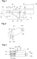
- Figure 1 shows a cleaning system 100 intended to clean a vehicle sensor 200 such as a light detection and ranging (Lidar) sensor.
- vehicle sensor 200 such as a light detection and ranging (Lidar) sensor.
- the cleaning system 100 comprises an accumulator 102 arranged for storing water and air that will be used for cleaning the sensor 200.
- the accumulator 102 comprises a water compartment 104 and an air compartment 106.
- the accumulator 102 will be more specifically described with regards to figures 2 and 3 .
- the cleaning system 100 comprises an outlet water electrovalve 116 and an outlet air electrovalve 118, for controlling the flow of water and air applied to the sensor 200.
- the outlet water electrovalve 116 is arranged in fluid communication with the water compartment 104 of the accumulator 102 and the outlet air electrovalve 118 is arranged in air communication with the air compartment 106 of the accumulator 102.
- Spray devices 120, 120' which are respectively in fluid communication with the outlet water electrovalve 116 and in air communication with the outlet air electrovalve 118.
- the cleaning system 100 comprises a water tank 108 and an air tank 110.
- the water tank 108 and the air tank 110 are pressurized.
- the cleaning system 100 comprises an inlet water valve 130 positioned between the water tank 108 and the water compartment 104 of the accumulator 102.
- the cleaning system 100 comprises an inlet air valve 132 positioned between the air tank 110 and the air compartment 106 of the accumulator 102.
- the inlet water valve 130 enables to control the flow of water supplied to the accumulator 102.
- the inlet air valve 132 enables to control the flow of air supplied to the accumulator 102.
- the fluid and air communications are preferably effected through pipes 122.
- a control unit 124 such as an electronic control unit (ECU) enables to control the supplying of water and air to the sensor 200 from the accumulator 102To this end, the control unit 124 is connected to a soil sensor 126 arranged to provide a signal to the control unit 124, when the sensor 200 is soiled, and the control unit 124 is connected to the outlet water electrovalve 116 and the outlet air electrovalve 118, in order to operate the electrovalves 116, 118 to supply water and air to the sensor 200 when the signal is received by the control unit 124.
- ECU electronice control unit
- the water compartment 104 and the air compartment 106 comprise a sensor 128 arranged to provide a signal representing the level of water and air in the accumulator.
- the control unit 124 enables to control the supplying of water and air to the accumulator 102. To this end, the control unit 124 is connected to the level sensors 128 positioned in the accumulator. Moreover, in the example of figure 1 , where the water and air tanks are pressurized, the inlet water valve 130 and the inlet air valve 132 are connected to the control unit 124. In this way, the control unit 124 operates the inlet water valve 130 and the inlet air valve 132 when a signal is received from the level sensors 128.
- the water tank 108 is arranged in fluid communication with a water pump 112, which is arranged in fluid communication with the water compartment 104 of the accumulator 102 and/or the air tank 110 is arranged in air communication with an air pump 114, which is arranged in air communication with the air compartment 106 of the accumulator 102.
- control unit 124 is connected to the water pump 112 and the air pump 114, in order to operate the pumps 112, 114 to refill the accumulator 102 when the signal is received by the control unit 124. More particularly, the control unit 124 is connected to two level sensors 128, one in the water compartment 104 and one in the air compartment.
- the accumulator 102 is cylindrical and the water compartment 104 can be concentrically arranged around the air compartment 106. This arrangement proves to be advantageous as it makes the accumulator very compact.
- the water compartment 104 comprises a water inlet 104a which is in fluidic communication through pipes 122 with the water tank 108 ( figure 1 ). Furthermore, the water compartment 104 comprises a water outlet 104b from where the water may exit to be able to spray upon the sensor 200 ( figure 1 ).
- the air compartment 106 comprises an air inlet 106a which is in air communication through pipes 122 with the air tank 110 ( figure 1 ), and the air compartment 106 comprises an air outlet 106b from where the air may exit to be able to spray upon the sensor 200 ( figure 1 ).
- the accumulator 102 comprises tensioning elements 134 in the water compartment 104 and in the air compartment 106.
- the tensioning elements 134 are of the mechanical type and are spring loaded.
- Each tensioning element 134 is comprised of, for example, a spring 134a with a membrane 134b.
- the tensioning elements 134 are arranged to mechanically store energy in order to supply energy to release water and/or air to the spray devices when the outlet water electrovalve 116 and/or the outlet air electrovalve 118 are operated by the control unit 124.
- Figures 4 to 6 illustrates a truck 300 with a vehicle sensor 200 and a cleaning system 100 to clean the vehicle sensor 200.
- the sensor 200 can be a Lidar sensor comprising a shell 202 and a screen 204.
- the cleaning system 100 comprises an accumulator 102 with a water compartment 104 and an air compartment 106 ( figures 1 to 3 ) which are connected to spray devices ( figure 1 ) via pipes 122, in order to spray water and/or air to the sensor 200 when outlet water electrovalve 116 and/or outlet air electrovalve 118 are operated by a control unit ( figure 1 ).
- the sensor 200 represented in figures 4 to 6 is a Lidar sensor disposed on a corner of the truck 300.
Landscapes
- Engineering & Computer Science (AREA)
- Mechanical Engineering (AREA)
- Water Supply & Treatment (AREA)
- Cleaning By Liquid Or Steam (AREA)
Description
- The invention relates to a sensor cleaning system for a vehicle. The invention further relates to a method for cleaning a sensor thanks to this cleaning system.
- The invention can be applied in vehicles including heavy-duty vehicles, such as trucks, buses and construction equipment, in particular in automated vehicles. Although the invention will be described with respect to an automated vehicle, the invention is not restricted to this particular vehicle, but may also be used in other vehicles including sensors.
- The invention is directed to a vehicle including a sensor such as a light detection and ranging (LIDAR), a camera, a RADAR, a SONAR, an infrared system...
- Vehicles, in particular autonomous vehicles, require sensors in order to capture data of a surrounding vehicle environment.
- Depending on the driving environment or/and weather conditions, sensors may become soiled and therefore may capture partial or incorrect data. This may lead to reduced safety outcome.
- In case a sensor is detected as soiled and therefore non-operational, the vehicle may need to switch to a safe mode which may include for instance coming to a halt and/or activating hazard lights.
- It is therefore desirable to avoid or limit the switching into a vehicle safe mode caused by a soiled sensor which is an unavoidable occurrence for any vehicle.
- While systems for cleaning sensors exist, they are not fully satisfactory. Indeed, they generally comprise a fluid tank kept under constant pressure to supply cleaning fluid through nozzles to a sensor, which needs cleaning. The fluid tank kept under constant pressure requires storing energy as pressure in the tank. This is not desirable as there is an intrinsic risk of leakage with pressurized tank and maintaining a tank under pressure tends to use some vehicle power.
EP-A-3168094 shows a similar cleaning system for cleaning a vehicle sensor. - An object of the invention is to provide a very reactive system for cleaning a sensor, that solve at least the previous problem of the prior art.
- To that end, according to a first aspect of the invention, the invention relates to a cleaning system for cleaning a vehicle sensor, comprising:
- an accumulator comprising:
- ∘ at least one cleaning fluid compartment provided with:
- ▪ at least one tensioning element,
- ▪ a cleaning fluid inlet for receiving cleaning fluid, and
- ▪ a cleaning fluid outlet for providing cleaning fluid in the form of a cleaning fluid jet,
- ∘ at least one gas compartment provided with:
- ▪ at least one tensioning element,
- ▪ a gas inlet for receiving gas, and
- ▪ a gas outlet for providing gas in the form of a gas jet,
- ∘ at least one cleaning fluid compartment provided with:
- a cleaning fluid spray device configured to spray cleaning fluid on the vehicle sensor,
- a gas spray device configured to spray gas on the vehicle sensor.
- By the provision of an accumulator comprising a cleaning fluid compartment and a gas compartment with tensioning elements, the cleaning device avoids having a cleaning fluid tank kept under constant pressure, and therefore avoids the risks of leakage of fluid.
- Moreover, the cleaning system will require less power, as no pump need to work all times to spray cleaning fluid to a sensor to be cleaned.
- In addition, the cleaning fluid and gas pressure applied to the sensor to be cleaned can be adapted thanks to the accumulator, for instance by managing the opening of the cleaning fluid outlet and/or the gas outlet.
- Besides, the accumulator is easily rechargeable via the cleaning fluid inlet and the gas inlet. Therefore, the cleaning system can be assigned to sensors of a vehicle, which are located at different areas of the vehicle.
- Furthermore, thanks to its compact size, the accumulator of the cleaning system can be placed nearby a sensor to be cleaned in order to have a very reactive cleaning system.
- According to one embodiment, the cleaning system comprises:
- an outlet cleaning fluid valve for controlling flow of cleaning fluid applied to the vehicle sensor, and
- an outlet gas valve for controlling flow of gas applied to the vehicle sensor.
- The tensioning elements are arranged to be operated when the valves are opened to spray cleaning fluid and gas from the accumulator to the sensor to be cleaned.
- According to one embodiment, the cleaning system comprises a control unit connected to the outlet cleaning fluid valve and the outlet gas valve. The control unit is configured to operate the valves in order to supply cleaning fluid and gas to the sensor to be cleaned.
- The outlet valves are preferably electrovalves.
- According to a further embodiment, the cleaning system further comprises:
- a cleaning fluid tank, and
- a gas tank.
- According to one embodiment, the gas tank is a pressurized tank.
- According to this embodiment, the cleaning system further comprises an inlet gas valve between the gas tank and the accumulator, for controlling the flow of gas supplied to the accumulator.
- The inlet gas valve is advantageously connected to the control unit. Therefore, the control unit is configured to operate the inlet gas valve in order to control the flow of gas supplied to the accumulator.
- The inlet gas valve is preferably an electrovalve.
- According to another embodiment, the gas tank is not a pressurized tank and the cleaning system comprises a gas pump arranged in communication with the gas tank and the gas inlet of the accumulator.
- The gas pump allows to refill the accumulator with gas. As the gas is not pressurized in the accumulator, this pump is with low flow capacity. Therefore, this pump does not involve many costs.
- The gas pump is advantageously connected to the control unit. Therefore, the control unit is configured to operate the gas pump in order to supply gas to the accumulator.
- According to one embodiment, the cleaning fluid tank is a pressurized tank.
- According to this embodiment, the cleaning system further comprises an inlet cleaning fluid valve between the cleaning fluid tank and the accumulator, for controlling the flow of cleaning fluid supplied to the accumulator.
- The inlet cleaning fluid valve is advantageously connected to the control unit. Therefore, the control unit is configured to operate the inlet cleaning fluid valve in order to control the flow of cleaning fluid supplied to the accumulator.
- The inlet cleaning fluid valve is preferably an electrovalve.
- According to another embodiment, the cleaning fluid tank is not a pressurized tank and the cleaning system comprises a cleaning fluid pump arranged in communication with the cleaning fluid tank and the cleaning fluid inlet of the accumulator.
- The cleaning fluid pump allows to refill the accumulator with cleaning fluid. As the cleaning fluid is not pressurized in the accumulator, this pump is with low flow capacity. Therefore, this pump do not involve many costs.
- The cleaning fluid pump is advantageously connected to the control unit. Therefore, the control unit is configured to operate the cleaning fluid pump in order to supply cleaning fluid to the accumulator.
- In addition, the cleaning system can comprise level sensors arranged to provide a signal representing the level of cleaning fluid and gas in the accumulator. In this way, the accumulator can be refilled when needed.
- The level sensors are advantageously connected to the control unit. Therefore, the control unit is configured to receive the signal and to operate the pumps and/or inlet valves based on the signal. The control unit is configured such that a signal indicating a level below a predetermined value operates the cleaning fluid pump or inlet cleaning fluid valve, and/or the gas pump or inlet gas valve to supply cleaning fluid and/or gas from the cleaning fluid container and/or the gas container to the accumulator and increase the level of cleaning fluid and/or gas in the accumulator.
- In an embodiment, the cleaning system comprises a soil sensor arranged to provide a signal when the sensor to be cleaned is soiled.
- According to this embodiment, the control unit is also connected to the soil sensor for measuring when the sensor to be cleaned is soiled. Therefore, the control unit is configured to operate the outlet valves based on the signal. The control unit is configured such that when a signal indicates that a sensor is soiled, the control unit operates the outlet cleaning fluid valve and/or the outlet gas valve to supply cleaning fluid and/or gas to the sensor to be cleaned.
- The control unit is preferably an electronic control unit (ECU).
- The tensioning elements are for example springs with membrane.
- The cleaning fluid can be water.
- The gas can be air.
- According to one embodiment, the cleaning fluid compartment is concentrically arranged around the gas compartment. This arrangement proves to be advantageous as it makes the accumulator very compact.
- According to a second aspect of the invention, these and other objectives are achieved by a method for cleaning a vehicle sensor using a cleaning system previously described, the method comprising:
- measuring the level of cleaning fluid and gas in the cleaning fluid and gas compartments of the accumulator;
- filling the cleaning fluid and gas compartments of the accumulator respectively with cleaning fluid and gas to store energy in the accumulator,
- spraying the cleaning fluid and the gas in order to supply cleaning fluid and gas on the vehicle sensor.
- By the provision of a method which comprises a step of filling the cleaning fluid and gas compartment of the accumulator respectively with cleaning fluid and gas, energy is stored in the accumulator without having a constant pressure in the cleaning fluid and gas compartments. Therefore, a sensor can be cleaned without risk of leakage of fluid.
- According to a third aspect of the invention, these and other objectives are achieved by a vehicle comprising a vehicle sensor associated with a cleaning system previously described.
- Further advantages and advantageous features of the invention are disclosed in the following description and in the dependent claims.
- With reference to the appended drawings, below follows a more detailed description of embodiments of the invention cited as examples.
- In the drawings:
-
Fig. 1 is a schematic view of a cleaning system according to the invention; -
Fig. 2 is a schematic perspective view of an accumulator of the cleaning system ofFig. 1 ; -
Fig. 3 is a schematic longitudinal cross-sectional view of the accumulator ofFig. 2 ; -
Fig. 3 and4 are schematic views of trucks with cleaning system associated to a vehicle sensor; -
Fig. 5 is a view of a cleaning system associated to a vehicle sensor mounted on a truck. -
Figure 1 shows acleaning system 100 intended to clean avehicle sensor 200 such as a light detection and ranging (Lidar) sensor. - The
cleaning system 100 comprises anaccumulator 102 arranged for storing water and air that will be used for cleaning thesensor 200. In particular, theaccumulator 102 comprises awater compartment 104 and anair compartment 106. Theaccumulator 102 will be more specifically described with regards tofigures 2 and 3 . - Moreover, the
cleaning system 100 comprises anoutlet water electrovalve 116 and anoutlet air electrovalve 118, for controlling the flow of water and air applied to thesensor 200. Theoutlet water electrovalve 116 is arranged in fluid communication with thewater compartment 104 of theaccumulator 102 and theoutlet air electrovalve 118 is arranged in air communication with theair compartment 106 of theaccumulator 102. - Water and air are applied to the
sensor 200 viaspray devices 120, 120' which are respectively in fluid communication with theoutlet water electrovalve 116 and in air communication with theoutlet air electrovalve 118. - As shown in
figure 1 , thecleaning system 100 comprises awater tank 108 and anair tank 110. In the example offigure 1 , thewater tank 108 and theair tank 110 are pressurized. In this example, thecleaning system 100 comprises aninlet water valve 130 positioned between thewater tank 108 and thewater compartment 104 of theaccumulator 102. Furthermore, thecleaning system 100 comprises aninlet air valve 132 positioned between theair tank 110 and theair compartment 106 of theaccumulator 102. - The
inlet water valve 130 enables to control the flow of water supplied to theaccumulator 102. Theinlet air valve 132 enables to control the flow of air supplied to theaccumulator 102. - In the cleaning system, the fluid and air communications are preferably effected through
pipes 122. - A
control unit 124 such as an electronic control unit (ECU) enables to control the supplying of water and air to thesensor 200 from the accumulator 102To this end, thecontrol unit 124 is connected to asoil sensor 126 arranged to provide a signal to thecontrol unit 124, when thesensor 200 is soiled, and thecontrol unit 124 is connected to theoutlet water electrovalve 116 and theoutlet air electrovalve 118, in order to operate theelectrovalves sensor 200 when the signal is received by thecontrol unit 124. - The
water compartment 104 and theair compartment 106 comprise asensor 128 arranged to provide a signal representing the level of water and air in the accumulator. - The
control unit 124 enables to control the supplying of water and air to theaccumulator 102. To this end, thecontrol unit 124 is connected to thelevel sensors 128 positioned in the accumulator. Moreover, in the example offigure 1 , where the water and air tanks are pressurized, theinlet water valve 130 and theinlet air valve 132 are connected to thecontrol unit 124. In this way, thecontrol unit 124 operates theinlet water valve 130 and theinlet air valve 132 when a signal is received from thelevel sensors 128. - In an example not represented the
water tank 108 is arranged in fluid communication with a water pump 112, which is arranged in fluid communication with thewater compartment 104 of theaccumulator 102 and/or theair tank 110 is arranged in air communication with an air pump 114, which is arranged in air communication with theair compartment 106 of theaccumulator 102. - In this example, the
control unit 124 is connected to the water pump 112 and the air pump 114, in order to operate the pumps 112, 114 to refill theaccumulator 102 when the signal is received by thecontrol unit 124. More particularly, thecontrol unit 124 is connected to twolevel sensors 128, one in thewater compartment 104 and one in the air compartment. - As illustrated in
figures 2 and 3 , theaccumulator 102 is cylindrical and thewater compartment 104 can be concentrically arranged around theair compartment 106. This arrangement proves to be advantageous as it makes the accumulator very compact. Thewater compartment 104, comprises awater inlet 104a which is in fluidic communication throughpipes 122 with the water tank 108 (figure 1 ). Furthermore, thewater compartment 104 comprises awater outlet 104b from where the water may exit to be able to spray upon the sensor 200 (figure 1 ). Similarly, theair compartment 106, comprises anair inlet 106a which is in air communication throughpipes 122 with the air tank 110 (figure 1 ), and theair compartment 106 comprises anair outlet 106b from where the air may exit to be able to spray upon the sensor 200 (figure 1 ). - As illustrated in
figure 3 , theaccumulator 102 comprises tensioningelements 134 in thewater compartment 104 and in theair compartment 106. In the embodiment of the invention thetensioning elements 134 are of the mechanical type and are spring loaded. Eachtensioning element 134 is comprised of, for example, aspring 134a with amembrane 134b. Thetensioning elements 134 are arranged to mechanically store energy in order to supply energy to release water and/or air to the spray devices when theoutlet water electrovalve 116 and/or theoutlet air electrovalve 118 are operated by thecontrol unit 124. -
Figures 4 to 6 illustrates atruck 300 with avehicle sensor 200 and acleaning system 100 to clean thevehicle sensor 200. - The
sensor 200 can be a Lidar sensor comprising ashell 202 and ascreen 204. As illustrated previously, thecleaning system 100 comprises anaccumulator 102 with awater compartment 104 and an air compartment 106 (figures 1 to 3 ) which are connected to spray devices (figure 1 ) viapipes 122, in order to spray water and/or air to thesensor 200 whenoutlet water electrovalve 116 and/oroutlet air electrovalve 118 are operated by a control unit (figure 1 ). - The
sensor 200 represented infigures 4 to 6 is a Lidar sensor disposed on a corner of thetruck 300. - It is to be understood that the present invention is not limited to the embodiments described above and illustrated in the drawings; rather, the skilled person will recognize that many changes and modifications may be made within the scope of the appended claims.
Claims (15)
- A cleaning system (100) for cleaning a vehicle sensor (200), comprising:- an accumulator (102) comprising:∘ at least one cleaning fluid compartment (104) provided with:▪ at least one tensioning element (134),▪ a cleaning fluid inlet (104a) for receiving cleaning fluid, and▪ a cleaning fluid outlet (104b) for providing cleaning fluid in the form of a cleaning fluid jet,∘ at least one gas compartment (106) provided with:▪ at least one tensioning element (134),▪ a gas inlet (106a) for receiving gas, and▪ a gas outlet (106b) for providing gas in the form of a gas jet,- a cleaning fluid spray device (120) configured to spray cleaning fluid on the vehicle sensor (200),- a gas spray device (120') configured to spray gas on the vehicle sensor (200).
- The cleaning system according to claim 1, characterized in that it comprises:- an outlet cleaning fluid valve (116) for controlling flow of cleaning fluid applied to the vehicle sensor, and- an outlet gas valve (118) for controlling flow of gas applied to the vehicle sensor, wherein the outlet cleaning valve (116) and the outlet gas valve (118) are preferably electrovalves.
- The cleaning system according to claim 2, characterized in that it comprises a control unit (124) connected to the outlet cleaning fluid valve (116) and the outlet gas valve (118).
- The cleaning system according to any one of claims 1 to 3, characterized in that it comprises:- a cleaning fluid tank (108),- a gas tank (110),- a cleaning fluid pump (112) connected to the cleaning fluid tank (108) and the cleaning fluid inlet (104a) of the accumulator (102), and- a gas pump (114) connected to the gas tank (110) and the gas inlet (106a) of the accumulator (102).
- The cleaning system according to claim 4 in combination with claim 3, characterized in that it the pumps (112, 114) are connected to the control unit (124).
- The cleaning system according to any one of claims 1 to 5, characterized in that it comprises level sensors (128) arranged to provide a signal representing the level of cleaning fluid and gas in the accumulator (102).
- The cleaning system according to claim 6 in combination with claim 3, characterized in that the level sensors (128) are connected to the control unit (124).
- The cleaning system according to any one of claims 4 to 7, characterized in that it comprises:- An inlet cleaning fluid valve (130) between the cleaning fluid tank (108) and the cleaning fluid pump (112), for controlling the flow of cleaning fluid through the cleaning fluid pump (112), and- An inlet gas valve (132) between the gas tank (110) and the gas pump (114), for controlling the flow of gas through the gas pump (114),wherein the inlet cleaning valve (130) and the inlet gas valve (132) are preferably electrovalves.
- The cleaning system according to claim 8 in combination with claim 3, characterized in that the inlet valves (130, 132) are connected to the control unit (124).
- The cleaning system according to any one of claims 1 to 9, characterized in that it comprises a soil sensor (126) arranged to provide an alert when the sensor (200) is soiled.
- The cleaning system according to claim 10 in combination with claim 3, characterized in that the control unit (124) is also connected to the soil sensor (126) for measuring when the sensor (200) is soiled.
- The cleaning system according to any one of claims 1 to 11, characterized in that the tensioning elements (134) are springs (134a) with membrane (134b).
- The cleaning system according to any one of claims 1 to 12, characterized in that the cleaning fluid compartment (104) is concentrically arranged around the gas compartment (106).
- A method for cleaning a vehicle sensor (200) using a cleaning system according to any one of claims 1 to 13, the method comprising:- measuring the level of cleaning fluid and gas in the cleaning fluid and gas compartments of the accumulator;- filling the cleaning fluid and gas compartments of the accumulator respectively with cleaning fluid and gas to store energy in the accumulator,- spraying the cleaning fluid and the gas in order to supply cleaning fluid and gas on the vehicle sensor.
- A vehicle (300) comprising a vehicle sensor (200) associated with a cleaning system (100) according to any one of claims 1 to 13.
Applications Claiming Priority (1)
| Application Number | Priority Date | Filing Date | Title |
|---|---|---|---|
| PCT/EP2020/052988 WO2021155931A1 (en) | 2020-02-06 | 2020-02-06 | A sensor cleaning system for a vehicle and a method for cleaning a sensor |
Publications (3)
| Publication Number | Publication Date |
|---|---|
| EP4100286A1 EP4100286A1 (en) | 2022-12-14 |
| EP4100286C0 EP4100286C0 (en) | 2024-04-10 |
| EP4100286B1 true EP4100286B1 (en) | 2024-04-10 |
Family
ID=69500749
Family Applications (1)
| Application Number | Title | Priority Date | Filing Date |
|---|---|---|---|
| EP20703999.1A Active EP4100286B1 (en) | 2020-02-06 | 2020-02-06 | A sensor cleaning system for a vehicle and a method for cleaning a sensor |
Country Status (4)
| Country | Link |
|---|---|
| US (1) | US12269438B2 (en) |
| EP (1) | EP4100286B1 (en) |
| CN (1) | CN115023375A (en) |
| WO (1) | WO2021155931A1 (en) |
Families Citing this family (1)
| Publication number | Priority date | Publication date | Assignee | Title |
|---|---|---|---|---|
| CN114321026B (en) * | 2022-03-11 | 2022-06-14 | 亿昇(天津)科技有限公司 | Cleaning device |
Family Cites Families (25)
| Publication number | Priority date | Publication date | Assignee | Title |
|---|---|---|---|---|
| DE3526430A1 (en) * | 1985-07-24 | 1987-02-05 | Swf Auto Electric Gmbh | Window-cleaning system |
| JP3857563B2 (en) * | 2001-08-24 | 2006-12-13 | アスモ株式会社 | Vehicle washer system |
| AU2004244652B2 (en) * | 2004-01-06 | 2011-09-29 | Eaton Corporation | Trapped gas removal in liquid-gas accumulator |
| US20110155192A1 (en) * | 2008-02-27 | 2011-06-30 | Nadeem Ahmad | System and apparatus for automatic built-in vehicle washing and other operations |
| US8739950B2 (en) * | 2008-09-25 | 2014-06-03 | Gm Global Technology Operations, Llc | Auxiliary pump system for hybrid powertrains |
| US8568262B2 (en) * | 2009-11-13 | 2013-10-29 | GM Global Technology Operations LLC | Transmission hydraulic control system having a main line feed accumulator |
| US8887498B2 (en) * | 2009-12-18 | 2014-11-18 | Gm Global Technology Operations, Llc | Transmission hydraulic control system having an accumulator bypass valve assembly |
| US8996257B2 (en) * | 2013-02-01 | 2015-03-31 | GM Global Technology Operations LLC | Vehicle anti-icing and de-icing systems and corresponding methods of operation |
| EP2815936B1 (en) * | 2013-06-18 | 2017-03-29 | Volvo Car Corporation | Windscreen washer |
| EP3105089B1 (en) * | 2014-02-14 | 2018-03-14 | Kautex Textron GmbH & Co. KG. | Air and fluid cleaning system and method for cleaning vehicle vision devices |
| WO2017080614A1 (en) | 2015-11-13 | 2017-05-18 | Fico Transpar, S.A. | System for cleaning a vehicle-mounted sensor |
| GB2538306B (en) * | 2015-05-15 | 2017-09-20 | Dyson Technology Ltd | Cleaning appliance |
| FR3050421B1 (en) * | 2016-04-21 | 2018-04-27 | Valeo Systemes D'essuyage | DEVICE FOR CLEANING A SENSOR OF AN OPTICAL DETECTION SYSTEM FOR A MOTOR VEHICLE |
| KR101813133B1 (en) * | 2016-06-03 | 2018-01-05 | 에이에스티 주식회사 | Camera lens cleaning devices for automobiles |
| US10220817B2 (en) * | 2016-07-18 | 2019-03-05 | Uber Technologies, Inc. | Sensor cleaning system for vehicles |
| US20180201231A1 (en) * | 2017-01-18 | 2018-07-19 | Denso Ten Limited | Foreign substance removal control device |
| WO2018187089A1 (en) | 2017-04-07 | 2018-10-11 | Uber Technologies, Inc. | Autonomous vehicle sensor cleaning system |
| US10857980B2 (en) * | 2017-04-07 | 2020-12-08 | Uatc, Llc | Autonomous vehicle sensor cleaning system |
| RU2662787C1 (en) * | 2017-06-08 | 2018-07-30 | Федеральное государственное бюджетное образовательное учреждение высшего образования "Казанский государственный энергетический университет" (ФГБОУ ВО "КГЭУ") | Wind and hydraulic accumulating electrical installation |
| US10189429B2 (en) | 2017-06-26 | 2019-01-29 | Ford Global Technologies, Llc | Vehicle sensor cleaning based on a vehicle occupancy status |
| WO2019012882A1 (en) | 2017-07-11 | 2019-01-17 | 株式会社デンソー | Onboard sensor cleaning device |
| JP7231550B2 (en) * | 2017-09-19 | 2023-03-01 | 株式会社小糸製作所 | Vehicle cleaning equipment |
| JP7077097B2 (en) * | 2018-03-28 | 2022-05-30 | 日立Astemo株式会社 | Air suspension system and camera cleaning system |
| US20200001830A1 (en) * | 2018-06-27 | 2020-01-02 | Geoffrey F. Deane | Systems and methods for perception surface cleaning, drying, and/or thermal management with localized heating |
| CN209406949U (en) * | 2018-12-29 | 2019-09-20 | 苏州小科清洁科技有限公司 | A kind of cleaning machine equipped with accumulator |
-
2020
- 2020-02-06 WO PCT/EP2020/052988 patent/WO2021155931A1/en not_active Ceased
- 2020-02-06 EP EP20703999.1A patent/EP4100286B1/en active Active
- 2020-02-06 US US17/795,443 patent/US12269438B2/en active Active
- 2020-02-06 CN CN202080094957.0A patent/CN115023375A/en active Pending
Also Published As
| Publication number | Publication date |
|---|---|
| EP4100286A1 (en) | 2022-12-14 |
| WO2021155931A1 (en) | 2021-08-12 |
| EP4100286C0 (en) | 2024-04-10 |
| US12269438B2 (en) | 2025-04-08 |
| CN115023375A (en) | 2022-09-06 |
| US20230060169A1 (en) | 2023-03-02 |
Similar Documents
| Publication | Publication Date | Title |
|---|---|---|
| US20220017047A1 (en) | Sensor Cleaning System for Vehicles | |
| US20180015908A1 (en) | Sensor cleaning system for vehicles | |
| US8291928B2 (en) | Vacuum-actuated shear valve device, system, and method, particularly for use in service station environments | |
| EP2815936B1 (en) | Windscreen washer | |
| KR20190133241A (en) | Autonomous cleaning system for cars | |
| US20250162543A1 (en) | Automated fluid dispensing systems for cleaning vision-based surfaces | |
| EP4194283B1 (en) | Fluidic distribution system for cleaning vehicle surfaces | |
| WO1998030394A1 (en) | Ink supply systems for ink jet printheads | |
| EP4247672B1 (en) | Cleaning device for a vehicle, vehicle and corresponding methods | |
| EP4100286B1 (en) | A sensor cleaning system for a vehicle and a method for cleaning a sensor | |
| US20230166694A1 (en) | Assisted sensor cleaning system | |
| US20240101072A1 (en) | Systems, methods, and technologies for cleaning and maintaining operability of vehicle sensors | |
| US5711456A (en) | Above ground fuel transfer module | |
| CN110979738A (en) | Pressure-drop type integrated power system and power propulsion method | |
| US7575015B2 (en) | Secondarily contained in-dispenser sump/pan system and method for capturing and monitoring leaks | |
| US10830031B2 (en) | Mobile distribution station having satellite dish | |
| US12576815B2 (en) | Distribution device, liquid distribution actuator, cleaning device, vehicle and method of operating a cleaning device | |
| CN114641645A (en) | Tank device for temperature pressure unloading of fuel cell tanks | |
| CN101979131A (en) | Pneumatic dual-urea tank urea one-way valve control water heating silicon controlled rectifier (SCR) urea system | |
| KR102882172B1 (en) | Remote Control and Remote Monitoring System for Tank Lorry | |
| CN207729236U (en) | A kind of unattended LNG gas stations | |
| US20250065849A1 (en) | Sensor cleaning system | |
| JP2519276Y2 (en) | Gas supply stand | |
| US5944091A (en) | Tank container cooling system | |
| EP4733153A1 (en) | Cleaning system and method |
Legal Events
| Date | Code | Title | Description |
|---|---|---|---|
| STAA | Information on the status of an ep patent application or granted ep patent |
Free format text: STATUS: UNKNOWN |
|
| STAA | Information on the status of an ep patent application or granted ep patent |
Free format text: STATUS: THE INTERNATIONAL PUBLICATION HAS BEEN MADE |
|
| PUAI | Public reference made under article 153(3) epc to a published international application that has entered the european phase |
Free format text: ORIGINAL CODE: 0009012 |
|
| STAA | Information on the status of an ep patent application or granted ep patent |
Free format text: STATUS: REQUEST FOR EXAMINATION WAS MADE |
|
| 17P | Request for examination filed |
Effective date: 20220705 |
|
| AK | Designated contracting states |
Kind code of ref document: A1 Designated state(s): AL AT BE BG CH CY CZ DE DK EE ES FI FR GB GR HR HU IE IS IT LI LT LU LV MC MK MT NL NO PL PT RO RS SE SI SK SM TR |
|
| DAV | Request for validation of the european patent (deleted) | ||
| DAX | Request for extension of the european patent (deleted) | ||
| GRAP | Despatch of communication of intention to grant a patent |
Free format text: ORIGINAL CODE: EPIDOSNIGR1 |
|
| STAA | Information on the status of an ep patent application or granted ep patent |
Free format text: STATUS: GRANT OF PATENT IS INTENDED |
|
| INTG | Intention to grant announced |
Effective date: 20231009 |
|
| GRAS | Grant fee paid |
Free format text: ORIGINAL CODE: EPIDOSNIGR3 |
|
| GRAA | (expected) grant |
Free format text: ORIGINAL CODE: 0009210 |
|
| STAA | Information on the status of an ep patent application or granted ep patent |
Free format text: STATUS: THE PATENT HAS BEEN GRANTED |
|
| AK | Designated contracting states |
Kind code of ref document: B1 Designated state(s): AL AT BE BG CH CY CZ DE DK EE ES FI FR GB GR HR HU IE IS IT LI LT LU LV MC MK MT NL NO PL PT RO RS SE SI SK SM TR |
|
| REG | Reference to a national code |
Ref country code: GB Ref legal event code: FG4D |
|
| REG | Reference to a national code |
Ref country code: CH Ref legal event code: EP |
|
| REG | Reference to a national code |
Ref country code: DE Ref legal event code: R096 Ref document number: 602020028713 Country of ref document: DE |
|
| REG | Reference to a national code |
Ref country code: IE Ref legal event code: FG4D |
|
| U01 | Request for unitary effect filed |
Effective date: 20240507 |
|
| U07 | Unitary effect registered |
Designated state(s): AT BE BG DE DK EE FI FR IT LT LU LV MT NL PT SE SI Effective date: 20240516 |
|
| PG25 | Lapsed in a contracting state [announced via postgrant information from national office to epo] |
Ref country code: IS Free format text: LAPSE BECAUSE OF FAILURE TO SUBMIT A TRANSLATION OF THE DESCRIPTION OR TO PAY THE FEE WITHIN THE PRESCRIBED TIME-LIMIT Effective date: 20240810 |
|
| PG25 | Lapsed in a contracting state [announced via postgrant information from national office to epo] |
Ref country code: HR Free format text: LAPSE BECAUSE OF FAILURE TO SUBMIT A TRANSLATION OF THE DESCRIPTION OR TO PAY THE FEE WITHIN THE PRESCRIBED TIME-LIMIT Effective date: 20240410 |
|
| PG25 | Lapsed in a contracting state [announced via postgrant information from national office to epo] |
Ref country code: GR Free format text: LAPSE BECAUSE OF FAILURE TO SUBMIT A TRANSLATION OF THE DESCRIPTION OR TO PAY THE FEE WITHIN THE PRESCRIBED TIME-LIMIT Effective date: 20240711 |
|
| PG25 | Lapsed in a contracting state [announced via postgrant information from national office to epo] |
Ref country code: ES Free format text: LAPSE BECAUSE OF FAILURE TO SUBMIT A TRANSLATION OF THE DESCRIPTION OR TO PAY THE FEE WITHIN THE PRESCRIBED TIME-LIMIT Effective date: 20240410 |
|
| PG25 | Lapsed in a contracting state [announced via postgrant information from national office to epo] |
Ref country code: PL Free format text: LAPSE BECAUSE OF FAILURE TO SUBMIT A TRANSLATION OF THE DESCRIPTION OR TO PAY THE FEE WITHIN THE PRESCRIBED TIME-LIMIT Effective date: 20240410 |
|
| PG25 | Lapsed in a contracting state [announced via postgrant information from national office to epo] |
Ref country code: PL Free format text: LAPSE BECAUSE OF FAILURE TO SUBMIT A TRANSLATION OF THE DESCRIPTION OR TO PAY THE FEE WITHIN THE PRESCRIBED TIME-LIMIT Effective date: 20240410 Ref country code: NO Free format text: LAPSE BECAUSE OF FAILURE TO SUBMIT A TRANSLATION OF THE DESCRIPTION OR TO PAY THE FEE WITHIN THE PRESCRIBED TIME-LIMIT Effective date: 20240710 Ref country code: IS Free format text: LAPSE BECAUSE OF FAILURE TO SUBMIT A TRANSLATION OF THE DESCRIPTION OR TO PAY THE FEE WITHIN THE PRESCRIBED TIME-LIMIT Effective date: 20240810 Ref country code: HR Free format text: LAPSE BECAUSE OF FAILURE TO SUBMIT A TRANSLATION OF THE DESCRIPTION OR TO PAY THE FEE WITHIN THE PRESCRIBED TIME-LIMIT Effective date: 20240410 Ref country code: GR Free format text: LAPSE BECAUSE OF FAILURE TO SUBMIT A TRANSLATION OF THE DESCRIPTION OR TO PAY THE FEE WITHIN THE PRESCRIBED TIME-LIMIT Effective date: 20240711 Ref country code: ES Free format text: LAPSE BECAUSE OF FAILURE TO SUBMIT A TRANSLATION OF THE DESCRIPTION OR TO PAY THE FEE WITHIN THE PRESCRIBED TIME-LIMIT Effective date: 20240410 Ref country code: RS Free format text: LAPSE BECAUSE OF FAILURE TO SUBMIT A TRANSLATION OF THE DESCRIPTION OR TO PAY THE FEE WITHIN THE PRESCRIBED TIME-LIMIT Effective date: 20240710 |
|
| REG | Reference to a national code |
Ref country code: DE Ref legal event code: R097 Ref document number: 602020028713 Country of ref document: DE |
|
| PG25 | Lapsed in a contracting state [announced via postgrant information from national office to epo] |
Ref country code: CZ Free format text: LAPSE BECAUSE OF FAILURE TO SUBMIT A TRANSLATION OF THE DESCRIPTION OR TO PAY THE FEE WITHIN THE PRESCRIBED TIME-LIMIT Effective date: 20240410 |
|
| PG25 | Lapsed in a contracting state [announced via postgrant information from national office to epo] |
Ref country code: RO Free format text: LAPSE BECAUSE OF FAILURE TO SUBMIT A TRANSLATION OF THE DESCRIPTION OR TO PAY THE FEE WITHIN THE PRESCRIBED TIME-LIMIT Effective date: 20240410 Ref country code: SK Free format text: LAPSE BECAUSE OF FAILURE TO SUBMIT A TRANSLATION OF THE DESCRIPTION OR TO PAY THE FEE WITHIN THE PRESCRIBED TIME-LIMIT Effective date: 20240410 |
|
| PG25 | Lapsed in a contracting state [announced via postgrant information from national office to epo] |
Ref country code: SM Free format text: LAPSE BECAUSE OF FAILURE TO SUBMIT A TRANSLATION OF THE DESCRIPTION OR TO PAY THE FEE WITHIN THE PRESCRIBED TIME-LIMIT Effective date: 20240410 |
|
| PG25 | Lapsed in a contracting state [announced via postgrant information from national office to epo] |
Ref country code: SM Free format text: LAPSE BECAUSE OF FAILURE TO SUBMIT A TRANSLATION OF THE DESCRIPTION OR TO PAY THE FEE WITHIN THE PRESCRIBED TIME-LIMIT Effective date: 20240410 Ref country code: SK Free format text: LAPSE BECAUSE OF FAILURE TO SUBMIT A TRANSLATION OF THE DESCRIPTION OR TO PAY THE FEE WITHIN THE PRESCRIBED TIME-LIMIT Effective date: 20240410 Ref country code: RO Free format text: LAPSE BECAUSE OF FAILURE TO SUBMIT A TRANSLATION OF THE DESCRIPTION OR TO PAY THE FEE WITHIN THE PRESCRIBED TIME-LIMIT Effective date: 20240410 Ref country code: CZ Free format text: LAPSE BECAUSE OF FAILURE TO SUBMIT A TRANSLATION OF THE DESCRIPTION OR TO PAY THE FEE WITHIN THE PRESCRIBED TIME-LIMIT Effective date: 20240410 |
|
| PLBE | No opposition filed within time limit |
Free format text: ORIGINAL CODE: 0009261 |
|
| STAA | Information on the status of an ep patent application or granted ep patent |
Free format text: STATUS: NO OPPOSITION FILED WITHIN TIME LIMIT |
|
| 26N | No opposition filed |
Effective date: 20250113 |
|
| U20 | Renewal fee for the european patent with unitary effect paid |
Year of fee payment: 6 Effective date: 20250224 |
|
| PG25 | Lapsed in a contracting state [announced via postgrant information from national office to epo] |
Ref country code: MC Free format text: LAPSE BECAUSE OF FAILURE TO SUBMIT A TRANSLATION OF THE DESCRIPTION OR TO PAY THE FEE WITHIN THE PRESCRIBED TIME-LIMIT Effective date: 20240410 |
|
| REG | Reference to a national code |
Ref country code: CH Ref legal event code: PL |
|
| PG25 | Lapsed in a contracting state [announced via postgrant information from national office to epo] |
Ref country code: CH Free format text: LAPSE BECAUSE OF NON-PAYMENT OF DUE FEES Effective date: 20250228 |
|
| GBPC | Gb: european patent ceased through non-payment of renewal fee |
Effective date: 20250206 |
|
| PG25 | Lapsed in a contracting state [announced via postgrant information from national office to epo] |
Ref country code: GB Free format text: LAPSE BECAUSE OF NON-PAYMENT OF DUE FEES Effective date: 20250206 |
|
| PG25 | Lapsed in a contracting state [announced via postgrant information from national office to epo] |
Ref country code: IE Free format text: LAPSE BECAUSE OF NON-PAYMENT OF DUE FEES Effective date: 20250206 |
|
| U20 | Renewal fee for the european patent with unitary effect paid |
Year of fee payment: 7 Effective date: 20260224 |