EP4100202B1 - Brazing sheet, brazing method, and heat exchanger manufacturing method - Google Patents
Brazing sheet, brazing method, and heat exchanger manufacturing method Download PDFInfo
- Publication number
- EP4100202B1 EP4100202B1 EP21704215.9A EP21704215A EP4100202B1 EP 4100202 B1 EP4100202 B1 EP 4100202B1 EP 21704215 A EP21704215 A EP 21704215A EP 4100202 B1 EP4100202 B1 EP 4100202B1
- Authority
- EP
- European Patent Office
- Prior art keywords
- brazing
- weight
- intermediate layer
- layer
- heat exchanger
- Prior art date
- Legal status (The legal status is an assumption and is not a legal conclusion. Google has not performed a legal analysis and makes no representation as to the accuracy of the status listed.)
- Active
Links
Images

Classifications
-
- B—PERFORMING OPERATIONS; TRANSPORTING
- B23—MACHINE TOOLS; METAL-WORKING NOT OTHERWISE PROVIDED FOR
- B23K—SOLDERING OR UNSOLDERING; WELDING; CLADDING OR PLATING BY SOLDERING OR WELDING; CUTTING BY APPLYING HEAT LOCALLY, e.g. FLAME CUTTING; WORKING BY LASER BEAM
- B23K35/00—Rods, electrodes, materials, or media, for use in soldering, welding, or cutting
- B23K35/22—Rods, electrodes, materials, or media, for use in soldering, welding, or cutting characterised by the composition or nature of the material
- B23K35/24—Selection of soldering or welding materials proper
- B23K35/28—Selection of soldering or welding materials proper with the principal constituent melting at less than 950°C
- B23K35/286—Al as the principal constituent
-
- B—PERFORMING OPERATIONS; TRANSPORTING
- B23—MACHINE TOOLS; METAL-WORKING NOT OTHERWISE PROVIDED FOR
- B23K—SOLDERING OR UNSOLDERING; WELDING; CLADDING OR PLATING BY SOLDERING OR WELDING; CUTTING BY APPLYING HEAT LOCALLY, e.g. FLAME CUTTING; WORKING BY LASER BEAM
- B23K35/00—Rods, electrodes, materials, or media, for use in soldering, welding, or cutting
- B23K35/02—Rods, electrodes, materials, or media, for use in soldering, welding, or cutting characterised by mechanical features, e.g. shape
- B23K35/0222—Rods, electrodes, materials, or media, for use in soldering, welding, or cutting characterised by mechanical features, e.g. shape for use in soldering or brazing
- B23K35/0233—Sheets or foils
- B23K35/0238—Sheets or foils layered
-
- B—PERFORMING OPERATIONS; TRANSPORTING
- B23—MACHINE TOOLS; METAL-WORKING NOT OTHERWISE PROVIDED FOR
- B23K—SOLDERING OR UNSOLDERING; WELDING; CLADDING OR PLATING BY SOLDERING OR WELDING; CUTTING BY APPLYING HEAT LOCALLY, e.g. FLAME CUTTING; WORKING BY LASER BEAM
- B23K1/00—Soldering, e.g. brazing, or unsoldering
- B23K1/0008—Soldering, e.g. brazing, or unsoldering specially adapted for particular articles or work
- B23K1/0012—Brazing of heat exchangers
-
- B—PERFORMING OPERATIONS; TRANSPORTING
- B23—MACHINE TOOLS; METAL-WORKING NOT OTHERWISE PROVIDED FOR
- B23K—SOLDERING OR UNSOLDERING; WELDING; CLADDING OR PLATING BY SOLDERING OR WELDING; CUTTING BY APPLYING HEAT LOCALLY, e.g. FLAME CUTTING; WORKING BY LASER BEAM
- B23K1/00—Soldering, e.g. brazing, or unsoldering
- B23K1/008—Soldering within a furnace
-
- B—PERFORMING OPERATIONS; TRANSPORTING
- B23—MACHINE TOOLS; METAL-WORKING NOT OTHERWISE PROVIDED FOR
- B23K—SOLDERING OR UNSOLDERING; WELDING; CLADDING OR PLATING BY SOLDERING OR WELDING; CUTTING BY APPLYING HEAT LOCALLY, e.g. FLAME CUTTING; WORKING BY LASER BEAM
- B23K1/00—Soldering, e.g. brazing, or unsoldering
- B23K1/19—Soldering, e.g. brazing, or unsoldering taking account of the properties of the materials to be soldered
-
- B—PERFORMING OPERATIONS; TRANSPORTING
- B23—MACHINE TOOLS; METAL-WORKING NOT OTHERWISE PROVIDED FOR
- B23K—SOLDERING OR UNSOLDERING; WELDING; CLADDING OR PLATING BY SOLDERING OR WELDING; CUTTING BY APPLYING HEAT LOCALLY, e.g. FLAME CUTTING; WORKING BY LASER BEAM
- B23K1/00—Soldering, e.g. brazing, or unsoldering
- B23K1/20—Preliminary treatment of work or areas to be soldered, e.g. in respect of a galvanic coating
- B23K1/206—Cleaning
-
- B—PERFORMING OPERATIONS; TRANSPORTING
- B23—MACHINE TOOLS; METAL-WORKING NOT OTHERWISE PROVIDED FOR
- B23K—SOLDERING OR UNSOLDERING; WELDING; CLADDING OR PLATING BY SOLDERING OR WELDING; CUTTING BY APPLYING HEAT LOCALLY, e.g. FLAME CUTTING; WORKING BY LASER BEAM
- B23K35/00—Rods, electrodes, materials, or media, for use in soldering, welding, or cutting
- B23K35/22—Rods, electrodes, materials, or media, for use in soldering, welding, or cutting characterised by the composition or nature of the material
- B23K35/38—Selection of media, e.g. special atmospheres for surrounding the working area
-
- B—PERFORMING OPERATIONS; TRANSPORTING
- B32—LAYERED PRODUCTS
- B32B—LAYERED PRODUCTS, i.e. PRODUCTS BUILT-UP OF STRATA OF FLAT OR NON-FLAT, e.g. CELLULAR OR HONEYCOMB, FORM
- B32B15/00—Layered products comprising a layer of metal
- B32B15/01—Layered products comprising a layer of metal all layers being exclusively metallic
- B32B15/016—Layered products comprising a layer of metal all layers being exclusively metallic all layers being formed of aluminium or aluminium alloys
-
- C—CHEMISTRY; METALLURGY
- C22—METALLURGY; FERROUS OR NON-FERROUS ALLOYS; TREATMENT OF ALLOYS OR NON-FERROUS METALS
- C22C—ALLOYS
- C22C21/00—Alloys based on aluminium
-
- C—CHEMISTRY; METALLURGY
- C22—METALLURGY; FERROUS OR NON-FERROUS ALLOYS; TREATMENT OF ALLOYS OR NON-FERROUS METALS
- C22C—ALLOYS
- C22C21/00—Alloys based on aluminium
- C22C21/02—Alloys based on aluminium with silicon as the next major constituent
-
- C—CHEMISTRY; METALLURGY
- C22—METALLURGY; FERROUS OR NON-FERROUS ALLOYS; TREATMENT OF ALLOYS OR NON-FERROUS METALS
- C22C—ALLOYS
- C22C21/00—Alloys based on aluminium
- C22C21/06—Alloys based on aluminium with magnesium as the next major constituent
-
- C—CHEMISTRY; METALLURGY
- C22—METALLURGY; FERROUS OR NON-FERROUS ALLOYS; TREATMENT OF ALLOYS OR NON-FERROUS METALS
- C22F—CHANGING THE PHYSICAL STRUCTURE OF NON-FERROUS METALS AND NON-FERROUS ALLOYS
- C22F1/00—Changing the physical structure of non-ferrous metals or alloys by heat treatment or by hot or cold working
- C22F1/04—Changing the physical structure of non-ferrous metals or alloys by heat treatment or by hot or cold working of aluminium or alloys based thereon
-
- F—MECHANICAL ENGINEERING; LIGHTING; HEATING; WEAPONS; BLASTING
- F28—HEAT EXCHANGE IN GENERAL
- F28D—HEAT-EXCHANGE APPARATUS, NOT PROVIDED FOR IN ANOTHER SUBCLASS, IN WHICH THE HEAT-EXCHANGE MEDIA DO NOT COME INTO DIRECT CONTACT
- F28D9/00—Heat-exchange apparatus having stationary plate-like or laminated conduit assemblies for both heat-exchange media, the media being in contact with different sides of a conduit wall
- F28D9/0031—Heat-exchange apparatus having stationary plate-like or laminated conduit assemblies for both heat-exchange media, the media being in contact with different sides of a conduit wall the conduits for one heat-exchange medium being formed by paired plates touching each other
- F28D9/0037—Heat-exchange apparatus having stationary plate-like or laminated conduit assemblies for both heat-exchange media, the media being in contact with different sides of a conduit wall the conduits for one heat-exchange medium being formed by paired plates touching each other the conduits for the other heat-exchange medium also being formed by paired plates touching each other
-
- F—MECHANICAL ENGINEERING; LIGHTING; HEATING; WEAPONS; BLASTING
- F28—HEAT EXCHANGE IN GENERAL
- F28F—DETAILS OF HEAT-EXCHANGE AND HEAT-TRANSFER APPARATUS, OF GENERAL APPLICATION
- F28F21/00—Constructions of heat-exchange apparatus characterised by the selection of particular materials
- F28F21/08—Constructions of heat-exchange apparatus characterised by the selection of particular materials of metal
- F28F21/081—Heat exchange elements made from metals or metal alloys
- F28F21/084—Heat exchange elements made from metals or metal alloys from aluminium or aluminium alloys
-
- B—PERFORMING OPERATIONS; TRANSPORTING
- B23—MACHINE TOOLS; METAL-WORKING NOT OTHERWISE PROVIDED FOR
- B23K—SOLDERING OR UNSOLDERING; WELDING; CLADDING OR PLATING BY SOLDERING OR WELDING; CUTTING BY APPLYING HEAT LOCALLY, e.g. FLAME CUTTING; WORKING BY LASER BEAM
- B23K2101/00—Articles made by soldering, welding or cutting
- B23K2101/04—Tubular or hollow articles
- B23K2101/14—Heat exchangers
-
- B—PERFORMING OPERATIONS; TRANSPORTING
- B23—MACHINE TOOLS; METAL-WORKING NOT OTHERWISE PROVIDED FOR
- B23K—SOLDERING OR UNSOLDERING; WELDING; CLADDING OR PLATING BY SOLDERING OR WELDING; CUTTING BY APPLYING HEAT LOCALLY, e.g. FLAME CUTTING; WORKING BY LASER BEAM
- B23K2103/00—Materials to be soldered, welded or cut
- B23K2103/08—Non-ferrous metals or alloys
- B23K2103/10—Aluminium or alloys thereof
-
- F—MECHANICAL ENGINEERING; LIGHTING; HEATING; WEAPONS; BLASTING
- F28—HEAT EXCHANGE IN GENERAL
- F28D—HEAT-EXCHANGE APPARATUS, NOT PROVIDED FOR IN ANOTHER SUBCLASS, IN WHICH THE HEAT-EXCHANGE MEDIA DO NOT COME INTO DIRECT CONTACT
- F28D21/00—Heat-exchange apparatus not covered by any of the groups F28D1/00 - F28D20/00
- F28D2021/0019—Other heat exchangers for particular applications; Heat exchange systems not otherwise provided for
- F28D2021/008—Other heat exchangers for particular applications; Heat exchange systems not otherwise provided for for vehicles
- F28D2021/0089—Oil coolers
-
- F—MECHANICAL ENGINEERING; LIGHTING; HEATING; WEAPONS; BLASTING
- F28—HEAT EXCHANGE IN GENERAL
- F28D—HEAT-EXCHANGE APPARATUS, NOT PROVIDED FOR IN ANOTHER SUBCLASS, IN WHICH THE HEAT-EXCHANGE MEDIA DO NOT COME INTO DIRECT CONTACT
- F28D21/00—Heat-exchange apparatus not covered by any of the groups F28D1/00 - F28D20/00
- F28D2021/0019—Other heat exchangers for particular applications; Heat exchange systems not otherwise provided for
- F28D2021/008—Other heat exchangers for particular applications; Heat exchange systems not otherwise provided for for vehicles
- F28D2021/0091—Radiators
- F28D2021/0094—Radiators for recooling the engine coolant
-
- F—MECHANICAL ENGINEERING; LIGHTING; HEATING; WEAPONS; BLASTING
- F28—HEAT EXCHANGE IN GENERAL
- F28F—DETAILS OF HEAT-EXCHANGE AND HEAT-TRANSFER APPARATUS, OF GENERAL APPLICATION
- F28F2275/00—Fastening; Joining
- F28F2275/04—Fastening; Joining by brazing
- F28F2275/045—Fastening; Joining by brazing with particular processing steps, e.g. by allowing displacement of parts during brazing or by using a reservoir for storing brazing material
Definitions
- the present invention relates to a brazing method capable of performing braze bonding under an inert gas atmosphere without requiring a flux, to a brazing sheet, and to a heat exchanger manufacturing method.
- An aluminum alloy is used for a vehicle heat exchanger component in consideration of the thermal conductivity, specific weight, and formability thereof, and braze bonding of a plurality of constituent components that are press formed from a brazing sheet cladded with the aluminum alloy is generally applied as a manufacturing method thereof.
- Brazing construction methods are, primarily, Control Atmosphere Brazing methods (hereinafter, CAB methods) performed in an atmosphere of an inert gas (N 2 , Ar, or the like) at atmospheric pressure and utilizing a fluoride based flux, and Vacuum Brazing Methods (hereinafter, VB methods) performed under high vacuum and not utilizing flux.
- CAB methods Control Atmosphere Brazing methods
- N 2 , Ar, or the like an atmosphere of an inert gas
- VB methods Vacuum Brazing Methods
- a non-corrosive fluoride based flux is coated during brazing to break down an oxide film on the brazing material layer of the cladded material, and the molten and flowed brazing material fills the gap between the adherend due to surface tension and causes a bond.
- an aluminum alloy having Mg added to the brazing material layer or the core material of the cladded material are sent to a vacuum furnace or an aluminum alloy that has not had Mg added to the brazing material layer or the core material is sent to a vacuum furnace together with Mg (for example, see patent documents 1 to 3).
- the Mg breaks down the oxide film on the brazing material layer of the cladded material during the brazing processing in the high temperature environment within the vacuum furnace, and furthermore, evaporated Mg captures traces of oxygen and moisture, which are brazing inhibitory substances which, exist near the surface, thereby enabling brazing.
- CAB methods have advantages in that they have comparatively quick formation cycles and inexpensive equipment costs, but they require a coating process for flux which breaks down the oxide film on the aluminum alloy surface and requiring a cleaning process for flux residue. Furthermore, there is risk of worsening of the work environment due to flux powder and effects on vehicle peripheral components due to insufficient removal of flux residue.
- Flux is not needed in VB methods, and therefore the risks caused by flux are eliminated, but mass-productivity is low due to it being performed using batch processing, and manufacturing cycles are long. Furthermore, contamination within the vacuum furnace due to Mg and countermeasures thereto are required. Moreover, high vacuum conditions are required, and therefore manufacturing costs are high.
- D4 discloses a process for the flux-free inert atmosphere production of an aluminium multilayer brazing sheet comprising a 3xxx core layer alloy, a 4xxx brazing layer alloy and optionally an interlayer between the core layer and the brazing layer on one or both sides of the core layer, a brazing method and a heat exchanger manufacturing method.
- a brazing sheet which is one aspect of the present invention, and a manufacturing process for a heat exchanger 1 using the same will be described with reference to FIGS. 1 to 4 .
- the brazing sheet of the present invention is composed of a brazing sheet used in brazing under an atmosphere of an inert gas and without needing flux, the brazing sheet having at least three layers, being cladded by an outermost layer of a brazing material layer via an intermediate layer on at least one side of a core material.
- the intermediate layer is composed of an aluminum alloy prepared such that Si and Fe are respectively no more than 0.20 weight% and Cu, Mn, and Cr are respectively no more than 0.10 weight%.
- the intermediate layer further contains no more than 4.5 weight% of Zn, the breakdown of the oxide film during brazing facilitated, the fillet formation rate improves, and it is possible to offer a function as a sacrificial anode for inhibiting corrosion of the core material on the face side to which refrigerant (coolant) is supplied.
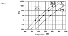
- the intermediate layer or the brazing material layer contain an element having a higher vapor pressure at 577 °C than Mg, the breakdown of the aluminum oxide film is facilitated and the fillet formation rate can be improved.
- At least 0.01 weight% of, for example, Zn or Na is contained as the element having a high vapor pressure ( FIG. 4 ).
- a satisfactory fillet formation rate can be obtained when Zn in the intermediate layer is in a range of at least 0.01 weight% and no more than 4.5 weight%.
- the thermal diffusion of the brazing process moves the brazing material layer, increases the flowability of the molten brazing material, and stabilizes brazing properties; in particular, when it is at least 0.02 weight%, the fillet formation rate and airtightness are satisfactory.
- the upper limit of 0.25 weight% is an upper limit based on an economical perspective since the effect does not change when more than this is added. Note that it is also possible to achieve stability of brazing properties when the core material layer is caused to contain Bi similar to the intermediate layer or the brazing material layer.
- a base plate 14 and fin plates 13, which form the exchange portion together with the core plates 11 and 12, are produced from an aluminum alloy (for example, JISA3003 material) using a forming method or the like.
- the fin plates 13 are formed into a well-known cross sectional wave shape.
- a jig is used to assemble the core plates 11 and 12, the fin plates 13, and the base plate 14 to appear as the stacked heat exchanger 1 as illustrated in FIG. 1 .
- the core plates 11 and 12 are stacked such that the face side on which the intermediate layer is disposed faces the coolant path.
- the stacked body formed from the core plates 11 and 12 is housed as a core portion 15 by a screen 2 illustrated FIG. 3 .
- the screen 2 is located using locating means provided on the base plate 14, and a gap with the stacked body is fixed.
- a brim portion 21 is disposed on the upper end of the tube portion enclosing the core portion 15 so as to cover the upper end of the minute gap D. Moreover, it is desirable for the gap h between the topmost portion of the core portion 15, which the brim portion 21opposes, and the lower face of the brim portion 21 to be no more than 5 mm.
- brazing When brazing is performed without flux under an atmosphere of inert gas based on a CAB method, it is necessary to protect the braze bond position of the stacked body from trace amounts of oxygen and water vapor in the inert gas, oxygen and water vapor being inhibitory factors for brazing.
- Mg evaporated from the brazing material layer of the brazing sheet cladded to the core plates 11 and 12 protects the bond positions from the foregoing oxygen and water vapor.
- a mesh belt continuous aluminum brazing furnace was used as the brazing furnace and nitrogen was used as the inert gas.
- Temperature conditions were as follows: the temperature of the workpiece was measured, and temperature control was performed to raise the temperature from room temperature to 600 °C in 30 minutes, hold it at 600 °C for three minutes, and thereafter cool it from 600 °C to 450 °C in four minutes.
- the heat exchangers 1 of examples 1 to 11 and comparative examples 1 to 6 obtained using the foregoing processes of S1 to S4 were evaluated for brazing properties, airtightness, and erosion resistance.
- brazing properties improve as the concentration of Si in the brazing material layer increases, and a satisfactory effect is obtained at at least 10 weight%.
- example 3 which exceeded the eutectic point, had a fillet formation rate that was even further satisfactory.
Landscapes
- Engineering & Computer Science (AREA)
- Mechanical Engineering (AREA)
- Chemical & Material Sciences (AREA)
- Materials Engineering (AREA)
- Metallurgy (AREA)
- Organic Chemistry (AREA)
- Physics & Mathematics (AREA)
- Thermal Sciences (AREA)
- General Engineering & Computer Science (AREA)
- Crystallography & Structural Chemistry (AREA)
- Laminated Bodies (AREA)
- Heat-Exchange Devices With Radiators And Conduit Assemblies (AREA)
Description
- The present invention relates to a brazing method capable of performing braze bonding under an inert gas atmosphere without requiring a flux, to a brazing sheet, and to a heat exchanger manufacturing method.
- An aluminum alloy is used for a vehicle heat exchanger component in consideration of the thermal conductivity, specific weight, and formability thereof, and braze bonding of a plurality of constituent components that are press formed from a brazing sheet cladded with the aluminum alloy is generally applied as a manufacturing method thereof.
- Brazing construction methods are, primarily, Control Atmosphere Brazing methods (hereinafter, CAB methods) performed in an atmosphere of an inert gas (N2, Ar, or the like) at atmospheric pressure and utilizing a fluoride based flux, and Vacuum Brazing Methods (hereinafter, VB methods) performed under high vacuum and not utilizing flux.
- In CAB methods, a non-corrosive fluoride based flux is coated during brazing to break down an oxide film on the brazing material layer of the cladded material, and the molten and flowed brazing material fills the gap between the adherend due to surface tension and causes a bond.
- In VB methods, an aluminum alloy having Mg added to the brazing material layer or the core material of the cladded material are sent to a vacuum furnace or an aluminum alloy that has not had Mg added to the brazing material layer or the core material is sent to a vacuum furnace together with Mg (for example, see
patent documents 1 to 3). Moreover, the Mg breaks down the oxide film on the brazing material layer of the cladded material during the brazing processing in the high temperature environment within the vacuum furnace, and furthermore, evaporated Mg captures traces of oxygen and moisture, which are brazing inhibitory substances which, exist near the surface, thereby enabling brazing. -
- [Patent Document 1]
JP 2014-237142 A - [Patent Document 2]
JP 2016-203193 A - [Patent Document 3]
JP 2017-74609 A WO2019/115422 - CAB methods have advantages in that they have comparatively quick formation cycles and inexpensive equipment costs, but they require a coating process for flux which breaks down the oxide film on the aluminum alloy surface and requiring a cleaning process for flux residue. Furthermore, there is risk of worsening of the work environment due to flux powder and effects on vehicle peripheral components due to insufficient removal of flux residue.
- Flux is not needed in VB methods, and therefore the risks caused by flux are eliminated, but mass-productivity is low due to it being performed using batch processing, and manufacturing cycles are long. Furthermore, contamination within the vacuum furnace due to Mg and countermeasures thereto are required. Moreover, high vacuum conditions are required, and therefore manufacturing costs are high.
- Accordingly, the need for brazing using a CAB method that does not use flux has increased in recent years, but in order to ensure brazing properties without flux, it is necessary to lower the melting point of the brazing material and increase the flowability. D4 discloses a process for the flux-free inert atmosphere production of an aluminium multilayer brazing sheet comprising a 3xxx core layer alloy, a 4xxx brazing layer alloy and optionally an interlayer between the core layer and the brazing layer on one or both sides of the core layer, a brazing method and a heat exchanger manufacturing method.
- However, there is a problem in that when flowability is increased, the brazing material causes erosion on the core material, whereby the core material strength is decreased, the brazing material cannot be effectively supplied to the bond portion, and satisfactory brazing and fillet formation cannot be achieved.
- The invention is disclosed in the appended set of claims.
- According to the present invention it is possible to inexpensively and cleanly improve brazing properties and mass-productivity without needing flux even substantially under atmospheric pressure without vacuum.
-
- [
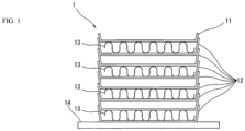
FIG. 1 ] An outline vertical cross sectional view illustrating a heat exchanger in an embodiment of the present invention. - [
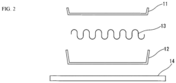
FIG. 2 ] An outline vertical cross sectional view illustrating constituent components of the heat exchanger inFIG. 1 . - [
FIG. 3 ] An outline vertical cross sectional view illustrating the positional relationship between a screen and an assembled structure body of the heat exchanger used in the brazing of an embodiment of the present invention. - [
FIG. 4 ] A vapor pressure curve of elements used in the brazing of an embodiment of the present invention. - Embodiments of the present invention will be described below with reference to drawings.
- The brazing sheet, brazing method, and heat exchanger manufacturing method of the present invention perform brazing of a brazing sheet under an atmosphere of inert gas without needing flux, thereby inexpensively and cleanly improving brazing properties and mass-productivity More specifically, when manufacturing the heat exchanger, a brazing sheet for the heat exchanger is used for brazing under an atmosphere of an inert gas such as nitrogen or argon at nearly atmospheric pressure, thereby inexpensively and cleanly improving brazing properties and mass-productivity, and achieving erosion resistance and strength.
- A brazing sheet, which is one aspect of the present invention, and a manufacturing process for a
heat exchanger 1 using the same will be described with reference toFIGS. 1 to 4 . - The brazing sheet of the present invention is composed of a brazing sheet used in brazing under an atmosphere of an inert gas and without needing flux, the brazing sheet having at least three layers, being cladded by an outermost layer of a brazing material layer via an intermediate layer on at least one side of a core material.
- The core material is composed of an aluminum alloy containing at least one or more elements from among at least 0.20 weight% and no more than 1.0 weight% of Cu, at least 0.8 weight% and no more than 1.8 weight% of Mn, and at least 0.25 weight% and no more than 1.5 weight% of Mg.
- The intermediate layer is composed of an aluminum alloy prepared such that Si and Fe are respectively no more than 0.20 weight% and Cu, Mn, and Cr are respectively no more than 0.10 weight%.
- The brazing material layer is composed of an aluminum alloy containing at least 10 weight% and no more than 15 weight% of Si and at least 0.25 weight% and no more than 1.5 weight% of Mg, and has a melting point no more than 575 °C according to a DSC method.
- At least one layer among the intermediate layer and the brazing material layer contain at least 0.02 weight% and no more than 0.25 weight% of Bi.
- The fluid coefficient of the brazing material layer on the side whereon the intermediate layer is disposed is, according to a drop type flow test, in a range of 0.40 to 0.60.
- The brazing sheet of the present invention is used for brazing under an atmosphere of inert gas near atmospheric pressure without using flux. The brazing sheet of is an aspect of a brazing sheet having at least three layers, being cladded by an outermost layer of the brazing material layer via the intermediate layer on at least one side of the core material. More specifically, a brazing material layer having a lower melting point than the core material is provided on both faces of the core material, and due to controlling element impurities between the core material and the brazing material layer, disposing an intermediate layer having a high melting point and low grain boundary density achieves an aspect of a cladded material having a four layer structure having a function for inhibiting erosion of the core material.
- When the intermediate layer further contains no more than 4.5 weight% of Zn, the breakdown of the oxide film during brazing facilitated, the fillet formation rate improves, and it is possible to offer a function as a sacrificial anode for inhibiting corrosion of the core material on the face side to which refrigerant (coolant) is supplied.
- The brazing material layer, in particular, is prepared such that Mg is at least 0.25 weight%, whereby the aluminum oxide film on the aluminum alloy surface can be broken down. Furthermore, Mg evaporated from the brazing material layer captures brazing inhibiting factors, such as O2 and H2O, which accumulate near the brazing position. However, by preparing it such that Mg is no more than 1.5 weight%, excessive Mg diffusing to the cladded material surface during the brazing process is avoided, and the formation of an oxide film of Mg on the brazing material layer surface is inhibited, and therefore, worsening of brazing properties can be prevented.
- Moreover, preparing it such that the fluid coefficient of the brazing material layer on the side whereon the intermediate layer is disposed is, according to a drop type flow test, in a range of 0.40 to 0.60 causes erosion from the brazing material to adjacent layers to be minimal, the brazing material to be effectively supplied to the bond, and a satisfactory fillet to be formed.
- When the intermediate layer or the brazing material layer contain an element having a higher vapor pressure at 577 °C than Mg, the breakdown of the aluminum oxide film is facilitated and the fillet formation rate can be improved. At least 0.01 weight% of, for example, Zn or Na is contained as the element having a high vapor pressure (
FIG. 4 ). In particular, a satisfactory fillet formation rate can be obtained when Zn in the intermediate layer is in a range of at least 0.01 weight% and no more than 4.5 weight%. - Moreover, when the intermediate layer or the brazing material layer contain a trace concentration of Bi, the thermal diffusion of the brazing process moves the brazing material layer, increases the flowability of the molten brazing material, and stabilizes brazing properties; in particular, when it is at least 0.02 weight%, the fillet formation rate and airtightness are satisfactory. However, the upper limit of 0.25 weight% is an upper limit based on an economical perspective since the effect does not change when more than this is added. Note that it is also possible to achieve stability of brazing properties when the core material layer is caused to contain Bi similar to the intermediate layer or the brazing material layer.
- The brazing sheet described above is utilized as a cladded sheet used in the brazing process in the manufacturing process of the
heat exchanger 1 of the present invention described below. - An example of manufacturing process S1 to S4 for the
heat exchanger 1 will be described with reference toFIGS. 1 to 3 . - S1: an aluminum alloy having prepared the elemental components of the core material, intermediate layer, and brazing material layer of the brazing sheet is ingot cast, and thereafter, homogenization processing, hot rolling, and cold rolling are performed to produce a cladded sheet having a predetermined thickness. Furthermore, the cladded sheet is annealed at a predetermined temperature and finished to a desired tempering. Note, the intermediate layer of the present cladded material also offers an effect as a sacrificial anode layer, and therefore is configured as a four layer clad disposing the intermediate layer on the coolant path face side.
- S2:
core plates heat exchanger 1 illustrated inFIG. 1 , are produced from the cladded sheet. Specifically, thecore plates - The
core plate 11 is, for example, produced using a plate disposed on the topmost portion of theheat exchanger 1 illustrated inFIG. 1 . Thecore plates 12 are stacked in the height direction of theheat exchanger 1 illustrated in the same drawing and are produced using plates that alternatingly form spaces to allow a fluid to be cooled and a refrigerant to flow in theheat exchanger 1. - A
base plate 14 andfin plates 13, which form the exchange portion together with thecore plates fin plates 13 are formed into a well-known cross sectional wave shape. - The formed body of the
core plates fin plates 13, and thebase plate 14 illustrated inFIG. 2 is suitably alkali cleaned at, for example, no more than pH5 or acid cleaned at, for example, at least pH9, and then further ultrasonic cleaned using pure water. Or, instead of cleaning in this manner, surface processing for improving brazing properties is performed by projecting a projection material at the surface of thecore plates core plates fin plates 13, and thebase plate 14. - S3: a jig is used to assemble the
core plates fin plates 13, and thebase plate 14 to appear as thestacked heat exchanger 1 as illustrated inFIG. 1 . In particular, thecore plates core plates core portion 15 by ascreen 2 illustratedFIG. 3 . Thescreen 2 is located using locating means provided on thebase plate 14, and a gap with the stacked body is fixed. - The
screen 2 is a stainless (for example, SUS304 having a plate thickness of 1 mm) rectangular tube capable of housing the stacked body, and specifically is formed to the vertical cross sectional partition shape illustrated as an example inFIG. 3 , and is disposed so as to cover and enclose the outer periphery of the stacked body. A minute gap D is ensured between the inner wall face 22 of thescreen 2 and the tip edge of the stacked body. - Furthermore, an opening
portion 20 is formed in the ceiling portion of thescreen 2, and abrim portion 21 is provided on the inner periphery of the top end portion of thescreen 2. The bottom face of thebrim portion 21 ensures an overlapping margin H between the stacked body and the periphery, and furthermore, ensures a gap h between the stacked body and the topmost portion. - The
screen 2 is composed of a thin metal sheet of stainless steel or another heat resistant metal having just enough heat resistance to be able to withstand the heating temperature during brazing, and is formed as a tube having a substantially quadrilateral cross section and enclosing thecore portion 15. Specifically, the inner wall face 11a of the tube portion is formed along the outer border of thecore plates core plates - Furthermore, in a preferable embodiment, a
brim portion 21 is disposed on the upper end of the tube portion enclosing thecore portion 15 so as to cover the upper end of the minute gap D. Moreover, it is desirable for the gap h between the topmost portion of thecore portion 15, which the brim portion 21opposes, and the lower face of thebrim portion 21 to be no more than 5 mm. - When the
brim portion 21 is viewed from above as a projection, it may overlap the periphery of thecore portion 15. The overlapping margin H of thebrim portion 21 and thecore portion 15 periphery is at least 0 mm. In other words, when viewed from above as a projection, at least thebrim portion 21 and thecore portion 15 are disposed continuously with no interstice. The overlapping margin H may be a suitably large value as well, but it is necessary for the top face of thescreen 2 to have a sufficiently large opening so as to allow displacement of gas between the internal space of thescreen 2 and external space. The overlapping margin H is preferably 5 mm. - Note, each of the foregoing dimensions are values at room temperature. In terms of the efficiency of the transfer of radiant heat from the furnace during brazing, it is desirable to have a larger heat receiving surface area on the top face of the core portion 3, and therefore, it is preferable to set the overlapping margin H of the
brim portion 21 such that the heat receiving surface area is at least 70% of the top face surface area. When the overlapping margin H is 5 mm, if, for example, the external dimensions of thecore plates screen 2 is not limited to the steel material, but may be formed of another metal material. - S4: the
screen 2 housing the stacked body is sent to a brazing furnace (not illustrated) without any flux and brazing is performed under an inert gas atmosphere and temperature profile conditions based on a CAB method. Accordingly, the position at which thecore plate 11 and thecore plates 12 overlap in the stacked body and the position at which thecore plates 12 overlap each other are brazed. Furthermore, thefin plates 13 are brazed to thecore plate 11 and thecore plates 12. - When brazing is performed without flux under an atmosphere of inert gas based on a CAB method, it is necessary to protect the braze bond position of the stacked body from trace amounts of oxygen and water vapor in the inert gas, oxygen and water vapor being inhibitory factors for brazing. In the CAB method, Mg evaporated from the brazing material layer of the brazing sheet cladded to the
core plates - However, it is thought that the evaporated MG is excluded from near the bond position due to diffusion from airflow and the like inside the brazing furnace, and there is a risk of having insufficient brazing at the position.
- In contrast to this, in the process in S4, the stacked body of
core plates screen 2, and therefore, the bond position is isolated from airflow and convective flow in the brazing furnace. Accordingly, diffusion of the evaporated Mg components is inhibited near the position, Mg retained nearby captures oxygen and water vapor, and therefore, brazing at the position is satisfactorily performed. - The
heat exchanger 1 illustrated inFIG. 1 manufactured using S1 to S4 is used as a heat exchanger for a vehicle internal combustion engine or for transmission lubricating oil. In theheat exchanger 1, a refrigerant (for example, coolant) is supplied to the spaces between thecore plates core plates 12 interposed withfin plates 13. However, a fluid to be cooled (for example, oil) is supplied to the spaces betweencore plates 12 where there is nofin plate 13. - The brazing sheet, brazing method, and heat exchanger manufacturing method of the present invention eliminate the drawbacks of CAB methods and VB methods and enable brazing that produces the benefits of both.
- Examples of the present invention will be described below.
- In S1, aluminum alloys prepared based on the components of the core material, intermediate layer, and brazing material layer shown in Table 1 were ingot cast, and thereafter, solution treatment, hot rolling, and cold rolling were performed to produce the 0.6 mm thick cladded sheets (clad 1 to 13) shown in Table 2. Thereafter, they were annealed at 380 °C and finished to a tempering O. The tempering O represents a state wherein annealing processing is completely performed and the material is softened. Note, in Table 1, the numerical values represent weight% values. Furthermore, "-" indicates a concentration of unavoidable impurities of less than 0.05 weight% (however, for the light doping element Bi, it indicates less than 0.01 weight%).
- The melting point of the brazing material layer of each cladded sheet was measured using differential scanning calorimetry (DSC) under a nitrogen gas atmosphere in a measurement temperature range from 30 °C to 700 °C, at a temperature elevation rate of 15 °C/minute.
- The fluid coefficient of the intermediate layer was determined using the following method.
- The opposite side face from the intermediate layer of each cladded sheet was machined to remove 0.1 mm, and the brazing material layer was removed; thereafter, 60 mm long, 30 mm wide, and 0.5 mm thick strip shaped test pieces were prepared. The test pieces were suspended such that the length direction of the test pieces was in line with the direction of gravity, and then sent to a brazing furnace. During brazing, an atmosphere of nitrogen gas was used as the inert gas, and first, the temperature was raised from room temperature to 600 °C for a required duration of 30 minutes, then the 600 °C was held for 3 minutes, after which it was cooled from 600 °C to 450 °C for a required duration of four minutes, and furthermore, cooled to room temperature for a required duration of 15 minutes. The fluid coefficient was calculated from the following equation.

- WO: weight of test piece before brazing
- WB: weight of lower 1/4 (15 mm) of test piece after brazing
- Cladding ratio: cladding ratio of brazing material layer of the test piece before brazing.
- 1.2: cladding ratio correction coefficient due to working the thickness of the test pieces to 0.5 mm.
- In S2, 80mm
square core plates fin plates 13 andbase plate 14 were produced using JISA3003 material. Next, surface processing was performed on thecore plates fin plates 13, and thebase plate 14 under the conditions shown in Table 3 using either an alkali cleaning at at least pH 9, acid cleaning at no more than pH 5, or shot blasting using sand as the projection material; thereafter, they were ultrasonic cleaned using pure water.[Table 3] Chemical Cleaning Chemical Components Time Temperature Post-Processing Acid Cleaning HF1%+ HNO 3 2%aqueous solution 90 Seconds Room Temperature Ultrasonically cleaned in pure water 1 minute x 2 timesAlkali Cleaning NaOH 6% aqueous solution 60 Seconds Room Temperature ↑ - In S3, they were assembled to appear as the
heat exchanger 1 illustrated inFIG. 1 , and thereafter housed in thescreen 2 illustrated inFIG. 3 . In the present example, the specifications for thescreen 2 and the positional relationship between it and theheat exchanger 1 are shown in Table 4.[Table 4] Screen Material Plate Thickness (mm) D (mm) L (mm) h (mm) Type 1SUS304 1 1 5 1 Type 2SUS304 1 5 5 1 Type 3 SUS304 1 10 5 1 - In S4, the
heat exchangers 1 of examples 1 to 11 and comparative examples 1 to 6 produced using the claddedmaterials 1 to 10 and surface processing conditions shown in Table 5 and housed in thescreen 2 having specifications shown in Table 4 were sent to a brazing furnace based on a CAB method to perform brazing without using flux. Brazing conditions are shown below. - A mesh belt continuous aluminum brazing furnace was used as the brazing furnace and nitrogen was used as the inert gas.
- Brazing was performed under conditions wherein oxygen concentration was 15 to 20 ppm and the dew point was -55 °C to -57 °C in a brazing furnace in a temperature zone of 450 °C to 600 °C.
- Temperature conditions were as follows: the temperature of the workpiece was measured, and temperature control was performed to raise the temperature from room temperature to 600 °C in 30 minutes, hold it at 600 °C for three minutes, and thereafter cool it from 600 °C to 450 °C in four minutes.
- The
heat exchangers 1 of examples 1 to 11 and comparative examples 1 to 6 obtained using the foregoing processes of S1 to S4 were evaluated for brazing properties, airtightness, and erosion resistance. - Brazing properties were evaluated as, "x: 90% or less, △: 90 to 99%, O: 99 to less than 100%, ⊚: 100%, ⊚+: 100% and large fillets" based on a fillet formation rate defined as, "fillet formation rate = length of formed fillet/total length to be brazed".
- Airtightness was evaluated as "O: no air leaks, x: air leaks" by performing an air leak test for one minute at a gauge pressure of 0.4 MPa and visually confirming in water whether there were air leaks.
- Erosion resistance was evaluated based on depth of corrosion defined as the greatest distance corroded to adjacent layers (intermediate layer and core material layer when there is no intermediate layer provided) by the brazing material layer at the bond portion of the
core plates core plates heat exchanger 1 obtained in S4. Specifically, it was evaluated as "⊚: corrosion depth of no more than 10 µm, O: no more than 50 µm, x: 50 µm or more, -: not evaluated" based on the corrosion depth. - The evaluation results of examples 1 to 11 and comparative examples 1 to 6 are shown in Table 5.
[Table 5] Cladded Material Surface Processing Screen Air Tightness Fillet Formation Rate Erosion Example 1 Clad 1Alkali Cleaning Type 1 O ⊚ ⊚ Example 2 Clad 2Alkali Cleaning Type 1 O O ⊚ Example 3 Clad 3 Alkali Cleaning Type 1 O ⊚+ ⊚ Example 4 Clad 4 Alkali Cleaning Type 1 O △∼○ ⊚ Example 5 Clad 5 Alkali Cleaning Type 1 O △∼○ ⊚ Example 6 Clad 6 Alkali Cleaning Type 1 O △~○ O Example 7 Clad 7 Alkali Cleaning Type 1 O O ⊚ Example 8 Clad 8 Alkali Cleaning Type 1 O ⊚+ ⊚ Example 9 Clad 9 Alkali Cleaning Type 1 O ⊚+ ⊚ Example 10 Clad 1Acid Cleaning Type 2 O O ⊚ Example 11 Clad 1Shot Blast Type 1 O △∼○ ⊚ Comparatit ve Example 1 Clad 10Alkali Cleaning Type 1 O △ X Comparative Example 2 Clad 11Alkali Cleaning Type 1 X X - Comparative Example 3 Clad 13Alkali Cleaning Type 1 X X - Comparative Example 4 Clad 12Alkali Cleaning Type 1 X X - Comparative Example 5 Clad 1Alkali Cleaning none X X - Comparative Example 6 Clad 1Alkali Cleaning Type 3 O × ⊚ - The following effects from the present invention can be confirmed based on the evaluation results in Table 5.
- In light of the comparison between examples 1 to 11 and comparative example 1, interposing an intermediate layer between the core material and the brazing material layer achieves a cladding ratio superior to comparative example 1, which was clad only by a brazing material layer, and therefore erosion resistance was improved. Furthermore, the intermediate layer contributed to improving the fillet formation rate (brazing properties).
- In light of the comparison of examples 1 to 3 and comparative example 2, brazing properties improve as the concentration of Si in the brazing material layer increases, and a satisfactory effect is obtained at at least 10 weight%. In particular, example 3, which exceeded the eutectic point, had a fillet formation rate that was even further satisfactory.
- In light of comparing examples 1, 4, 5 and comparative example 3, brazing properties are practically ensured when Mg concentration is at least 0.25 weight% and no more than 1.5 weight%. The concentration lower limit of 0.25 weight% is thought to be the lower limit concentration for breaking down the aluminum oxide film and for evaporated Mg to capture O2 and H2O, which are brazing inhibitory substances, near the brazing. However, the concentration upper limit of 1.5 weight% is in consideration of excess Mg not used for breaking down the aluminum oxide film forming a rigid oxidized magnesium film on the brazing material surface and conversely worsening the brazing properties. Furthermore, it is recognized that a brazing material layer not containing Mg not only cannot satisfy the brazing properties, but cannot satisfy airtightness either.
- In light of the comparison between example 6 and comparative example 4, it is recognized that traces of Bi concentration in the brazing material layer stabilize the brazing properties, and in particular, when it is at least 0.02 weight%, airtightness and the fillet formation rate can be satisfied. It is thought that this is due to the trace amounts of Bi improving the flowability of the molten brazing material.
- In light of the results of example 7, it is recognized that adding Bi to layers other than the brazing material layer such as the intermediate layer improves the effect of brazing properties, airtightness, and erosion resistance. This is thought to be due to Bi being able to easily thermally diffuse during the brazing process, and adding it to the intermediate layer or the core material rather than adding it directly to the brazing material layer causes thermal diffusion to the brazing material layer to be facilitated due to the heat in the brazing process (S4). Therefore, the brazing material layer, core material layer, or intermediate layer containing Bi can improve the effects.
- In light of the results of examples 8 and 9, adding an element having a higher vapor pressure than Mg, for example, Zn or Na, to the intermediate layer or the brazing material layer (
FIG. 4 ) further improves the fillet formation rate. The mechanism thereof is unclear, but it is presumed to be due, in addition to Mg breaking down the oxide film, there is a possibility that the high vapor pressure of Zn or Na may facilitate the breakdown of the oxide film. Note that it is recognized that when the element having a high vapor pressure is at least 0.01 weight% the fillet formation rate is improved. - In light of the results of example 10, performing chemical cleaning processing using an acid aqueous solution or an alkali aqueous solution before brazing further enables satisfactory brazing properties to be obtained.
- In light of the results of example 11, performing a mechanical surface processing by shot blasting using a projection material before brazing had no effect on the brazing properties.
- In light of the results of examples 1 to 11, comparative example 5, and comparative example 6, jointly using a screen capable of housing the stacked body of plates formed from the brazing sheet of the present invention in the brazing process enables a further facilitation of satisfactory brazing. In other words, housing the stacked body in the screen inhibits diffusion of Mg evaporated from the brazing material layer in the stacked body during brazing due to forced convection of the inert gas in the brazing furnace, and in addition, inhibits the supply of oxygen and water vapor, which are brazing inhibiting factors, through the inert gas to the stacked body, and therefore, satisfactory brazing can be facilitated.
- As is clear in light of the results of the foregoing examples and comparative examples, according to the present invention, it is possible to manufacture a heat exchanger made of an aluminum alloy having satisfactory brazing properties even without using a flux and even in an atmosphere of inert gas substantially at atmospheric pressure without vacuum. Therefore, it is possible to braze an aluminum product capable of eliminating flux residue, which becomes an impure substance in a finished product, significantly improving the brazing environment, and achieving the same productivity and low equipment cost as a CAB method, for which flux was a prerequisite.
-
- 1... heat exchanger
- 11, 12... core plate
- 13... fin plate
- 14... base plate
- 2... screen, 20... opening portion, 21... brim portion, 22... inner wall face
- D... minute gap, H... overlapping margin, h... gap
| Aluminum Alloy | Si | Fe | Cu | Mn | Mg | Zn | Na | Bi |
| Brazing Material 1 | 12.0 | 0.10 | - | - | 0.63 | - | - | 0.25 |
| Brazing Material 2 | 10.0 | 0.10 | - | - | 0.63 | - | - | 0.25 |
| Brazing Material 3 | 14.0 | 0.10 | - | - | 0.63 | - | - | 0.25 |
| Brazing Material 4 | 7.5 | 0.10 | - | - | 0.63 | - | - | 0.25 |
| Brazing Material 5 | 12.0 | 0.10 | - | - | 0.25 | - | - | 0.25 |
| Brazing Material 6 | 12.0 | 0.10 | - | - | 1.5 | - | - | 0.25 |
| Brazing Material 7 | 12.0 | 0.10 | - | - | 0.63 | - | - | 0.02 |
| Brazing Material 8 | 12.0 | 0.10 | - | - | 0.63 | - | - | - |
| Brazing Material 9 | 12.0 | 0.10 | - | - | 0.63 | 3.0 | - | 0.25 |
| Brazing Material 10 | 12.0 | 0.10 | - | - | 0.63 | - | 0.01 | - |
| Brazing Material 11 | 12.0 | 0.10 | - | - | - | - | - | 0.25 |
| Intermediate Layer 1 | 0.10 | 0.10 | - | - | - | 1.5 | - | - |
| Intermediate Layer 2 | 0.10 | 0.10 | - | - | - | 1.5 | - | 0.25 |
| Core Material 1 | 0.75 | 0.10 | 0.20 | 1.5 | - | - | - | - |
| Cladded Material | Brazing Material in | Intermediate Layer | Core Material | Brazing Material out | Brazing Material Melting Point (°C) | Fluid Coefficient * |
| Clad 1 | Brazing Material 1 | Intermediate Layer 1 | Core Material 1 | Brazing Material 1 | 573 | 0.54 |
| Clad 2 | Brazing Material 2 | Intermediate Layer 1 | Core Material 1 | Brazing Material 2 | 573 | 0.41 |
| Clad 3 | Brazing Material 3 | Intermediate Layer 1 | Core Material 1 | Brazing Material 3 | 572 | 0.45 |
| Clad 4 | Brazing Material 5 | Intermediate Layer 1 | Core Material 1 | Brazing Material 4 | 575 | 0.40 |
| Clad 5 | Brazing Material 6 | Intermediate Layer 1 | Core Material 1 | Brazing Material 6 | 559 | 0.58 |
| Clad 6 | Brazing Material 7 | Intermediate Layer 1 | Core Material 1 | Brazing Material 7 | 573 | 0.48 |
| Clad 7 | Brazing Material 8 | Intermediate Layer 2 | Core Material 1 | Brazing Material 8 | 573 | 0.50 |
| Clad 8 | Brazing Material 9 | Intermediate Layer 1 | Core Material 1 | Brazing Material 9 | 572 | 0.59 |
| Clad 9 | Brazing Material 10 | Intermediate Layer 1 | Core Material 1 | Brazing Material 10 | 572 | 0.57 |
| Clad 10 | Brazing Material 1 | - | Core Material 1 | Brazing Material 1 | 574 | 0.84 |
| Clad 11 | Brazing Material 4 | Intermediate Layer 1 | Core Material 1 | Brazing Material 4 | 574 | 0.21 |
| Clad 12 | Brazing Material 8 | Intermediate Layer 1 | Core Material 1 | Brazing Material 8 | 573 | 0.30 |
| Clad 13 | Brazing Material 11 | Intermediate Layer 1 | Core Material 1 | Brazing Material 11 | 579 | 0.36 |
Claims (12)
- A brazing sheet used for brazing under an atmosphere of an inert gas without flux, comprising at least three layers and being cladded by an outermost layer of a brazing material layer via an intermediate layer on at least one face of a core material, wherein:the core material is composed of an aluminum alloy containing at least one element from among at least 0.20 weight% and no more than 1.0 weight% of Cu, at least 0.8 weight% and no more than 1.8 weight% of Mn, and at least 0.25 weight% and no more than 1.5 weight% of Mg;the intermediate layer is composed of an aluminum alloy prepared such that Si and Fe are respectively no more than 0.20 weight% and Cu, Mn, and Cr are respectively no more than 0.10 weight%;the brazing material layer is composed of an aluminum alloy containing at least 10 weight% and no more than 15 weight% of Si and at least 0.25 weight% and no more than 1.5 weight% of Mg, and has a melting point no more than 575 °C according to a DSC method;
at least one layer among the intermediate layer and the brazing material layer contain at least 0.02 weight% and no more than 0.25 weight% of Bi; anda fluid coefficient of the brazing material layer on the side whereon the intermediate layer is disposed is, according to a drop type flow test, in a range of 0.40 to 0.60. - The brazing sheet according to claim 1, wherein at least one layer among the core material, the intermediate layer, or the brazing material layer further comprises an element having a higher vapor pressure than Mg at 577 °C.
- The brazing sheet according to claim 2, further comprising at least 0.01 weight% of at least one of Zn or Na as the element having a higher vapor pressure than Mg.
- The brazing sheet according to claim 3, wherein the intermediate layer further comprises at least 4.5 weight% of Zn.
- A brazing method, comprising: stacking plates obtained by forming the brazing sheet according to any one of claims 1 to 4 to assemble a heat exchange portion of a heat exchanger, and thereafter brazing and bonding a position of the plates that overlap together when stacked.
- The brazing method according to claim 5, comprising a process wherein a stacked body of the plates is housed by a screen having a vertical cross sectional partition shape to cover and enclose a periphery of the stacked body, and thereafter, brazing is performed.
- The brazing method according to claim 6, wherein a minute gap is ensured between an inner wall face of the screen and a tip edge of the stacked body.
- The brazing method according to claim 7, further comprising a brim portion at a periphery of a top end portion of the screen, wherein a lower face of the brim portion ensures an overlapping margin between the stacked body and the periphery, and furthermore, ensures a gap between it and a topmost portion of the stacked body.
- The brazing method according to any one of claims 5 to 8, wherein the brazing sheet or the plates are chemically cleaned using an acid aqueous solution or an alkali aqueous solution before brazing.
- The brazing method according to any one of claims 5 to 9, wherein projection material is projected at the brazing sheet or the plates before brazing.
- A heat exchanger manufacturing method, comprising a process for brazing the heat exchanger according to the brazing method according to any one of claims 5 to 10.
- The heat exchanger manufacturing method according to claim 11, wherein the heat exchanger is used for cooling a vehicle internal combustion engine or transmission lubricating oil.
Applications Claiming Priority (2)
| Application Number | Priority Date | Filing Date | Title |
|---|---|---|---|
| JP2020019366A JP2021122850A (en) | 2020-02-07 | 2020-02-07 | Brazing sheet, brazing method and heat exchanger manufacturing method |
| PCT/EP2021/052765 WO2021156417A1 (en) | 2020-02-07 | 2021-02-05 | Brazing sheet, brazing method, and heat exchanger manufacturing method |
Publications (2)
| Publication Number | Publication Date |
|---|---|
| EP4100202A1 EP4100202A1 (en) | 2022-12-14 |
| EP4100202B1 true EP4100202B1 (en) | 2023-12-27 |
Family
ID=74572752
Family Applications (1)
| Application Number | Title | Priority Date | Filing Date |
|---|---|---|---|
| EP21704215.9A Active EP4100202B1 (en) | 2020-02-07 | 2021-02-05 | Brazing sheet, brazing method, and heat exchanger manufacturing method |
Country Status (5)
| Country | Link |
|---|---|
| US (1) | US12121998B2 (en) |
| EP (1) | EP4100202B1 (en) |
| JP (1) | JP2021122850A (en) |
| CN (1) | CN115052706B (en) |
| WO (1) | WO2021156417A1 (en) |
Families Citing this family (5)
| Publication number | Priority date | Publication date | Assignee | Title |
|---|---|---|---|---|
| JP7840152B2 (en) * | 2021-12-28 | 2026-04-03 | Maアルミニウム株式会社 | Aluminum alloy brazing sheet to suppress warping during brazing. |
| JP2023141036A (en) * | 2022-03-23 | 2023-10-05 | 株式会社Uacj | aluminum alloy brazing sheet |
| JP2024082528A (en) * | 2022-12-08 | 2024-06-20 | マーレジャパン株式会社 | Manufacturing method of brazed joint |
| CN116638167A (en) * | 2023-03-20 | 2023-08-25 | 南京百灵汽车电气机械有限公司 | A Method of Improving the Qualification Rate of Heat Exchanger Brazing |
| CN116921791B (en) * | 2023-09-15 | 2023-11-14 | 淄博市特种设备检验研究院 | Brazing forming treatment system for steel plate type radiator |
Family Cites Families (39)
| Publication number | Priority date | Publication date | Assignee | Title |
|---|---|---|---|---|
| US2817895A (en) * | 1956-08-16 | 1957-12-31 | Horizons Inc | Soldering flux composition and method of soldering with same |
| US3321828A (en) * | 1962-01-02 | 1967-05-30 | Gen Electric | Aluminum brazing |
| US3941293A (en) * | 1969-09-22 | 1976-03-02 | Societe Anonyme Des Usines Chausson | Brazing jig for aluminum radiator cores |
| US4701127A (en) * | 1982-12-10 | 1987-10-20 | Borg-Warner Corporation | Controlled atmosphere capsule for fluxless brazing |
| US5340015A (en) * | 1993-03-22 | 1994-08-23 | Westinghouse Electric Corp. | Method for applying brazing filler metals |
| JP3276790B2 (en) * | 1994-11-11 | 2002-04-22 | 古河電気工業株式会社 | Method for producing aluminum alloy brazing sheet, heat exchanger using the brazing sheet, and method for producing the heat exchanger |
| JPH0985433A (en) * | 1995-09-19 | 1997-03-31 | Sky Alum Co Ltd | Fluxless non-oxidizing atmosphere brazing method |
| US6031751A (en) * | 1998-01-20 | 2000-02-29 | Reliance Electric Industrial Company | Small volume heat sink/electronic assembly |
| KR100951504B1 (en) * | 2001-09-28 | 2010-04-07 | 후루카와 스카이 가부시키가이샤 | Soldering method of aluminum or aluminum alloy and brazing sheet made of aluminum alloy |
| JP3801016B2 (en) * | 2001-10-31 | 2006-07-26 | 三菱アルミニウム株式会社 | Method for producing high-strength aluminum alloy brazing sheet for heat exchangers with excellent brazeability, formability and erosion resistance |
| US6815086B2 (en) * | 2001-11-21 | 2004-11-09 | Dana Canada Corporation | Methods for fluxless brazing |
| CA2531316C (en) * | 2003-08-29 | 2012-11-13 | Corus Aluminium Walzprodukte Gmbh | High strength aluminium alloy brazing sheet, brazed assembly and method for producing same |
| FR2862984B1 (en) * | 2003-11-28 | 2006-11-03 | Pechiney Rhenalu | ALUMINUM ALLOY BAND FOR SOLDERING |
| JP4342396B2 (en) | 2004-07-22 | 2009-10-14 | 古河スカイ株式会社 | Brazing method |
| JP4474228B2 (en) | 2004-08-05 | 2010-06-02 | 株式会社デンソー | Brazing method |
| JP4634789B2 (en) * | 2004-12-24 | 2011-02-16 | 古河スカイ株式会社 | Brazing method |
| JP5339556B2 (en) | 2012-01-13 | 2013-11-13 | 古河スカイ株式会社 | Brazing sheet for flux-free brazing and method for producing the same |
| EP2660043B1 (en) * | 2012-05-04 | 2021-03-03 | Hydro Aluminium Rolled Products GmbH | Use of an aluminium clad sheet for fluxless brazing |
| JP5844212B2 (en) * | 2012-05-07 | 2016-01-13 | 株式会社Uacj | Aluminum alloy brazing sheet |
| JP6154122B2 (en) | 2012-12-12 | 2017-06-28 | 株式会社マーレ フィルターシステムズ | Multi-plate stacked heat exchanger |
| US8707747B1 (en) * | 2012-12-14 | 2014-04-29 | Rohr, Inc. | Forming a shaped sandwich panel with a die and a pressure vessel |
| JP5352001B1 (en) * | 2012-12-21 | 2013-11-27 | 三菱アルミニウム株式会社 | Brazing method and brazing structure of aluminum material |
| JP6184176B2 (en) | 2013-06-06 | 2017-08-23 | 大陽日酸株式会社 | Brazing furnace and brazing method of aluminum material |
| JP6132347B2 (en) | 2013-07-31 | 2017-05-24 | 株式会社Uacj | Aluminum alloy brazing sheet and method for producing the same |
| JP6376836B2 (en) | 2013-08-22 | 2018-08-22 | 株式会社マーレ フィルターシステムズ | Heat exchanger |
| SI3062949T2 (en) | 2013-10-29 | 2023-08-31 | Swep International Ab | A method of brazing a plate heat exchanger using scren printed brazing material |
| JP2016203193A (en) | 2015-04-17 | 2016-12-08 | 株式会社Uacj | Aluminum alloy sheet and method for producing the same, and aluminum brazing sheet using the aluminum alloy sheet |
| JP6363555B2 (en) * | 2015-04-28 | 2018-07-25 | 株式会社デンソー | Aluminum heat exchanger |
| JP6468983B2 (en) | 2015-10-16 | 2019-02-13 | 株式会社Uacj | Aluminum alloy brazing sheet, manufacturing method thereof, aluminum alloy sheet and heat exchanger |
| JP6463262B2 (en) * | 2015-12-28 | 2019-01-30 | 株式会社Uacj | Aluminum alloy brazing sheet and method for producing aluminum alloy heat exchanger |
| JP6055573B1 (en) | 2016-06-23 | 2016-12-27 | 三菱アルミニウム株式会社 | Brazing sheet for flux-free brazing, flux-free brazing method and flux-free brazing method for heat exchanger |
| JP6487974B2 (en) | 2017-08-17 | 2019-03-20 | 株式会社Uacj | Aluminum alloy brazing sheet for heat exchanger and method for producing aluminum alloy brazing sheet for heat exchanger |
| FR3074717B1 (en) * | 2017-12-12 | 2019-11-08 | Constellium Neuf-Brisach | ALUMINUM MULTILAYER SOLDER FOR BRAZING WITHOUT FLOW |
| JP7256760B2 (en) | 2018-02-02 | 2023-04-12 | 株式会社Uacj | Brazing method |
| JP6909744B2 (en) * | 2018-03-07 | 2021-07-28 | 株式会社Uacj | Flux-free brazing aluminum alloy brazing sheet |
| DE112019004755T5 (en) * | 2018-10-26 | 2021-06-02 | Uacj Corporation | ALUMINUM ALLOY SOLDER PLATE AND MANUFACTURING PROCESS THEREOF |
| JP7240978B2 (en) * | 2019-07-26 | 2023-03-16 | 株式会社Uacj | Aluminum alloy brazing sheet and manufacturing method thereof |
| EP4083246A4 (en) * | 2020-02-04 | 2023-05-31 | Kabushiki Kaisha Kobe Seiko Sho (Kobe Steel, Ltd.) | ALUMINUM ALLOY BRAZING SHEET |
| JP7431599B2 (en) * | 2020-02-07 | 2024-02-15 | マーレジャパン株式会社 | How to braze a heat exchanger |
-
2020
- 2020-02-07 JP JP2020019366A patent/JP2021122850A/en active Pending
-
2021
- 2021-02-05 EP EP21704215.9A patent/EP4100202B1/en active Active
- 2021-02-05 CN CN202180013082.1A patent/CN115052706B/en active Active
- 2021-02-05 US US17/798,069 patent/US12121998B2/en active Active
- 2021-02-05 WO PCT/EP2021/052765 patent/WO2021156417A1/en not_active Ceased
Also Published As
| Publication number | Publication date |
|---|---|
| EP4100202A1 (en) | 2022-12-14 |
| US20230080566A1 (en) | 2023-03-16 |
| US12121998B2 (en) | 2024-10-22 |
| CN115052706A (en) | 2022-09-13 |
| CN115052706B (en) | 2023-08-18 |
| JP2021122850A (en) | 2021-08-30 |
| WO2021156417A1 (en) | 2021-08-12 |
Similar Documents
| Publication | Publication Date | Title |
|---|---|---|
| EP4100202B1 (en) | Brazing sheet, brazing method, and heat exchanger manufacturing method | |
| CN114734161B (en) | Aluminum alloy brazing sheet, manufacturing method thereof, aluminum alloy sheet and heat exchanger | |
| EP2103702B1 (en) | Aluminum alloy brazing sheet for heat exchanger | |
| EP3459676B1 (en) | Brazing sheet for flux-free brazing, flux-free brazing method and method for producing heat exchanger | |
| EP2243589B1 (en) | Aluminum alloy clad sheet for heat exchangers and method of producing the same | |
| JP5486592B2 (en) | Aluminum alloy strip of brazed heat exchanger tube | |
| EP3573781B1 (en) | Aluminum material for fluxfree cab brazing | |
| JP7431599B2 (en) | How to braze a heat exchanger | |
| CN109072352A (en) | The method for welding of brazing sheet and its manufacturing method and constructed of aluminium body | |
| US10625379B2 (en) | Aluminum alloy cladding material, manufacturing method therefor, and heat exchanger using said aluminum alloy cladding material | |
| CN110678292A (en) | Aluminum alloy brazing sheet | |
| CN114423563B (en) | Flux-free brazing method for aluminum brazing sheet and aluminum member | |
| CN118159387A (en) | Aluminum alloy brazing plate and method for manufacturing the same | |
| JP4033562B2 (en) | Aluminum alloy heat exchanger brazing structure manufacturing method, aluminum alloy heat exchanger and brazed sheet molded body for heat exchanger | |
| EP4164836B1 (en) | Aluminium alloy multi-layered brazing sheet material for flux-free brazing | |
| CN115038546B (en) | Multi-layer aluminum brazing sheet material | |
| CN110997958B (en) | Aluminum alloy brazing sheet for heat exchanger | |
| CN110662626A (en) | Brazing method for aluminum alloy brazing sheet, and method for manufacturing heat exchanger | |
| JP5302114B2 (en) | Aluminum alloy brazing sheet for vacuum brazing | |
| JP6763036B2 (en) | Aluminum alloy brazing sheet, its manufacturing method, aluminum alloy sheet and heat exchanger | |
| JP2000167688A (en) | Aluminum alloy clad material for heat exchangers with excellent brazing and corrosion resistance | |
| EP3859023A1 (en) | Aluminium alloy multi-layered brazing sheet material for fluxfree brazing | |
| CN115698352B (en) | Aluminum alloy brazing plates and aluminum alloy brazing bodies | |
| JP5219550B2 (en) | Aluminum alloy brazing sheet for vacuum brazing | |
| JP2000135590A (en) | High strength aluminum alloy clad material for heat exchanger |
Legal Events
| Date | Code | Title | Description |
|---|---|---|---|
| STAA | Information on the status of an ep patent application or granted ep patent |
Free format text: STATUS: UNKNOWN |
|
| STAA | Information on the status of an ep patent application or granted ep patent |
Free format text: STATUS: THE INTERNATIONAL PUBLICATION HAS BEEN MADE |
|
| PUAI | Public reference made under article 153(3) epc to a published international application that has entered the european phase |
Free format text: ORIGINAL CODE: 0009012 |
|
| STAA | Information on the status of an ep patent application or granted ep patent |
Free format text: STATUS: REQUEST FOR EXAMINATION WAS MADE |
|
| 17P | Request for examination filed |
Effective date: 20220623 |
|
| AK | Designated contracting states |
Kind code of ref document: A1 Designated state(s): AL AT BE BG CH CY CZ DE DK EE ES FI FR GB GR HR HU IE IS IT LI LT LU LV MC MK MT NL NO PL PT RO RS SE SI SK SM TR |
|
| DAV | Request for validation of the european patent (deleted) | ||
| DAX | Request for extension of the european patent (deleted) | ||
| GRAP | Despatch of communication of intention to grant a patent |
Free format text: ORIGINAL CODE: EPIDOSNIGR1 |
|
| STAA | Information on the status of an ep patent application or granted ep patent |
Free format text: STATUS: GRANT OF PATENT IS INTENDED |
|
| INTG | Intention to grant announced |
Effective date: 20230731 |
|
| GRAS | Grant fee paid |
Free format text: ORIGINAL CODE: EPIDOSNIGR3 |
|
| GRAA | (expected) grant |
Free format text: ORIGINAL CODE: 0009210 |
|
| STAA | Information on the status of an ep patent application or granted ep patent |
Free format text: STATUS: THE PATENT HAS BEEN GRANTED |
|
| AK | Designated contracting states |
Kind code of ref document: B1 Designated state(s): AL AT BE BG CH CY CZ DE DK EE ES FI FR GB GR HR HU IE IS IT LI LT LU LV MC MK MT NL NO PL PT RO RS SE SI SK SM TR |
|
| REG | Reference to a national code |
Ref country code: GB Ref legal event code: FG4D |
|
| REG | Reference to a national code |
Ref country code: CH Ref legal event code: EP |
|
| REG | Reference to a national code |
Ref country code: DE Ref legal event code: R096 Ref document number: 602021008095 Country of ref document: DE |
|
| REG | Reference to a national code |
Ref country code: IE Ref legal event code: FG4D |
|
| PG25 | Lapsed in a contracting state [announced via postgrant information from national office to epo] |
Ref country code: GR Free format text: LAPSE BECAUSE OF FAILURE TO SUBMIT A TRANSLATION OF THE DESCRIPTION OR TO PAY THE FEE WITHIN THE PRESCRIBED TIME-LIMIT Effective date: 20240328 |
|
| REG | Reference to a national code |
Ref country code: LT Ref legal event code: MG9D |
|
| PG25 | Lapsed in a contracting state [announced via postgrant information from national office to epo] |
Ref country code: LT Free format text: LAPSE BECAUSE OF FAILURE TO SUBMIT A TRANSLATION OF THE DESCRIPTION OR TO PAY THE FEE WITHIN THE PRESCRIBED TIME-LIMIT Effective date: 20231227 |
|
| PG25 | Lapsed in a contracting state [announced via postgrant information from national office to epo] |
Ref country code: ES Free format text: LAPSE BECAUSE OF FAILURE TO SUBMIT A TRANSLATION OF THE DESCRIPTION OR TO PAY THE FEE WITHIN THE PRESCRIBED TIME-LIMIT Effective date: 20231227 |
|
| PG25 | Lapsed in a contracting state [announced via postgrant information from national office to epo] |
Ref country code: LT Free format text: LAPSE BECAUSE OF FAILURE TO SUBMIT A TRANSLATION OF THE DESCRIPTION OR TO PAY THE FEE WITHIN THE PRESCRIBED TIME-LIMIT Effective date: 20231227 Ref country code: GR Free format text: LAPSE BECAUSE OF FAILURE TO SUBMIT A TRANSLATION OF THE DESCRIPTION OR TO PAY THE FEE WITHIN THE PRESCRIBED TIME-LIMIT Effective date: 20240328 Ref country code: FI Free format text: LAPSE BECAUSE OF FAILURE TO SUBMIT A TRANSLATION OF THE DESCRIPTION OR TO PAY THE FEE WITHIN THE PRESCRIBED TIME-LIMIT Effective date: 20231227 Ref country code: ES Free format text: LAPSE BECAUSE OF FAILURE TO SUBMIT A TRANSLATION OF THE DESCRIPTION OR TO PAY THE FEE WITHIN THE PRESCRIBED TIME-LIMIT Effective date: 20231227 Ref country code: BG Free format text: LAPSE BECAUSE OF FAILURE TO SUBMIT A TRANSLATION OF THE DESCRIPTION OR TO PAY THE FEE WITHIN THE PRESCRIBED TIME-LIMIT Effective date: 20240327 |
|
| REG | Reference to a national code |
Ref country code: NL Ref legal event code: MP Effective date: 20231227 |
|
| REG | Reference to a national code |
Ref country code: AT Ref legal event code: MK05 Ref document number: 1644082 Country of ref document: AT Kind code of ref document: T Effective date: 20231227 |
|
| PG25 | Lapsed in a contracting state [announced via postgrant information from national office to epo] |
Ref country code: NL Free format text: LAPSE BECAUSE OF FAILURE TO SUBMIT A TRANSLATION OF THE DESCRIPTION OR TO PAY THE FEE WITHIN THE PRESCRIBED TIME-LIMIT Effective date: 20231227 |
|
| PG25 | Lapsed in a contracting state [announced via postgrant information from national office to epo] |
Ref country code: SE Free format text: LAPSE BECAUSE OF FAILURE TO SUBMIT A TRANSLATION OF THE DESCRIPTION OR TO PAY THE FEE WITHIN THE PRESCRIBED TIME-LIMIT Effective date: 20231227 Ref country code: RS Free format text: LAPSE BECAUSE OF FAILURE TO SUBMIT A TRANSLATION OF THE DESCRIPTION OR TO PAY THE FEE WITHIN THE PRESCRIBED TIME-LIMIT Effective date: 20231227 Ref country code: NO Free format text: LAPSE BECAUSE OF FAILURE TO SUBMIT A TRANSLATION OF THE DESCRIPTION OR TO PAY THE FEE WITHIN THE PRESCRIBED TIME-LIMIT Effective date: 20240327 Ref country code: NL Free format text: LAPSE BECAUSE OF FAILURE TO SUBMIT A TRANSLATION OF THE DESCRIPTION OR TO PAY THE FEE WITHIN THE PRESCRIBED TIME-LIMIT Effective date: 20231227 Ref country code: LV Free format text: LAPSE BECAUSE OF FAILURE TO SUBMIT A TRANSLATION OF THE DESCRIPTION OR TO PAY THE FEE WITHIN THE PRESCRIBED TIME-LIMIT Effective date: 20231227 Ref country code: HR Free format text: LAPSE BECAUSE OF FAILURE TO SUBMIT A TRANSLATION OF THE DESCRIPTION OR TO PAY THE FEE WITHIN THE PRESCRIBED TIME-LIMIT Effective date: 20231227 |
|
| PG25 | Lapsed in a contracting state [announced via postgrant information from national office to epo] |
Ref country code: IS Free format text: LAPSE BECAUSE OF FAILURE TO SUBMIT A TRANSLATION OF THE DESCRIPTION OR TO PAY THE FEE WITHIN THE PRESCRIBED TIME-LIMIT Effective date: 20240427 |
|
| PG25 | Lapsed in a contracting state [announced via postgrant information from national office to epo] |
Ref country code: CZ Free format text: LAPSE BECAUSE OF FAILURE TO SUBMIT A TRANSLATION OF THE DESCRIPTION OR TO PAY THE FEE WITHIN THE PRESCRIBED TIME-LIMIT Effective date: 20231227 Ref country code: AT Free format text: LAPSE BECAUSE OF FAILURE TO SUBMIT A TRANSLATION OF THE DESCRIPTION OR TO PAY THE FEE WITHIN THE PRESCRIBED TIME-LIMIT Effective date: 20231227 |
|
| PG25 | Lapsed in a contracting state [announced via postgrant information from national office to epo] |
Ref country code: SK Free format text: LAPSE BECAUSE OF FAILURE TO SUBMIT A TRANSLATION OF THE DESCRIPTION OR TO PAY THE FEE WITHIN THE PRESCRIBED TIME-LIMIT Effective date: 20231227 |
|
| PG25 | Lapsed in a contracting state [announced via postgrant information from national office to epo] |
Ref country code: SM Free format text: LAPSE BECAUSE OF FAILURE TO SUBMIT A TRANSLATION OF THE DESCRIPTION OR TO PAY THE FEE WITHIN THE PRESCRIBED TIME-LIMIT Effective date: 20231227 Ref country code: SK Free format text: LAPSE BECAUSE OF FAILURE TO SUBMIT A TRANSLATION OF THE DESCRIPTION OR TO PAY THE FEE WITHIN THE PRESCRIBED TIME-LIMIT Effective date: 20231227 Ref country code: RO Free format text: LAPSE BECAUSE OF FAILURE TO SUBMIT A TRANSLATION OF THE DESCRIPTION OR TO PAY THE FEE WITHIN THE PRESCRIBED TIME-LIMIT Effective date: 20231227 Ref country code: IT Free format text: LAPSE BECAUSE OF FAILURE TO SUBMIT A TRANSLATION OF THE DESCRIPTION OR TO PAY THE FEE WITHIN THE PRESCRIBED TIME-LIMIT Effective date: 20231227 Ref country code: IS Free format text: LAPSE BECAUSE OF FAILURE TO SUBMIT A TRANSLATION OF THE DESCRIPTION OR TO PAY THE FEE WITHIN THE PRESCRIBED TIME-LIMIT Effective date: 20240427 Ref country code: EE Free format text: LAPSE BECAUSE OF FAILURE TO SUBMIT A TRANSLATION OF THE DESCRIPTION OR TO PAY THE FEE WITHIN THE PRESCRIBED TIME-LIMIT Effective date: 20231227 Ref country code: CZ Free format text: LAPSE BECAUSE OF FAILURE TO SUBMIT A TRANSLATION OF THE DESCRIPTION OR TO PAY THE FEE WITHIN THE PRESCRIBED TIME-LIMIT Effective date: 20231227 Ref country code: AT Free format text: LAPSE BECAUSE OF FAILURE TO SUBMIT A TRANSLATION OF THE DESCRIPTION OR TO PAY THE FEE WITHIN THE PRESCRIBED TIME-LIMIT Effective date: 20231227 |
|
| PG25 | Lapsed in a contracting state [announced via postgrant information from national office to epo] |
Ref country code: PL Free format text: LAPSE BECAUSE OF FAILURE TO SUBMIT A TRANSLATION OF THE DESCRIPTION OR TO PAY THE FEE WITHIN THE PRESCRIBED TIME-LIMIT Effective date: 20231227 Ref country code: PT Free format text: LAPSE BECAUSE OF FAILURE TO SUBMIT A TRANSLATION OF THE DESCRIPTION OR TO PAY THE FEE WITHIN THE PRESCRIBED TIME-LIMIT Effective date: 20240429 |
|
| PG25 | Lapsed in a contracting state [announced via postgrant information from national office to epo] |
Ref country code: PT Free format text: LAPSE BECAUSE OF FAILURE TO SUBMIT A TRANSLATION OF THE DESCRIPTION OR TO PAY THE FEE WITHIN THE PRESCRIBED TIME-LIMIT Effective date: 20240429 Ref country code: PL Free format text: LAPSE BECAUSE OF FAILURE TO SUBMIT A TRANSLATION OF THE DESCRIPTION OR TO PAY THE FEE WITHIN THE PRESCRIBED TIME-LIMIT Effective date: 20231227 |
|
| PG25 | Lapsed in a contracting state [announced via postgrant information from national office to epo] |
Ref country code: MC Free format text: LAPSE BECAUSE OF FAILURE TO SUBMIT A TRANSLATION OF THE DESCRIPTION OR TO PAY THE FEE WITHIN THE PRESCRIBED TIME-LIMIT Effective date: 20231227 |
|
| REG | Reference to a national code |
Ref country code: DE Ref legal event code: R097 Ref document number: 602021008095 Country of ref document: DE Ref country code: CH Ref legal event code: PL |
|
| PG25 | Lapsed in a contracting state [announced via postgrant information from national office to epo] |
Ref country code: DK Free format text: LAPSE BECAUSE OF FAILURE TO SUBMIT A TRANSLATION OF THE DESCRIPTION OR TO PAY THE FEE WITHIN THE PRESCRIBED TIME-LIMIT Effective date: 20231227 |
|
| PG25 | Lapsed in a contracting state [announced via postgrant information from national office to epo] |
Ref country code: LU Free format text: LAPSE BECAUSE OF NON-PAYMENT OF DUE FEES Effective date: 20240205 |
|
| PG25 | Lapsed in a contracting state [announced via postgrant information from national office to epo] |
Ref country code: CH Free format text: LAPSE BECAUSE OF NON-PAYMENT OF DUE FEES Effective date: 20240229 |
|
| PG25 | Lapsed in a contracting state [announced via postgrant information from national office to epo] |
Ref country code: LU Free format text: LAPSE BECAUSE OF NON-PAYMENT OF DUE FEES Effective date: 20240205 Ref country code: DK Free format text: LAPSE BECAUSE OF FAILURE TO SUBMIT A TRANSLATION OF THE DESCRIPTION OR TO PAY THE FEE WITHIN THE PRESCRIBED TIME-LIMIT Effective date: 20231227 Ref country code: CH Free format text: LAPSE BECAUSE OF NON-PAYMENT OF DUE FEES Effective date: 20240229 |
|
| PLBE | No opposition filed within time limit |
Free format text: ORIGINAL CODE: 0009261 |
|
| STAA | Information on the status of an ep patent application or granted ep patent |
Free format text: STATUS: NO OPPOSITION FILED WITHIN TIME LIMIT |
|
| 26N | No opposition filed |
Effective date: 20240930 |
|
| REG | Reference to a national code |
Ref country code: BE Ref legal event code: MM Effective date: 20240229 |
|
| PG25 | Lapsed in a contracting state [announced via postgrant information from national office to epo] |
Ref country code: BE Free format text: LAPSE BECAUSE OF NON-PAYMENT OF DUE FEES Effective date: 20240229 |
|
| PG25 | Lapsed in a contracting state [announced via postgrant information from national office to epo] |
Ref country code: FR Free format text: LAPSE BECAUSE OF NON-PAYMENT OF DUE FEES Effective date: 20240227 |
|
| PG25 | Lapsed in a contracting state [announced via postgrant information from national office to epo] |
Ref country code: IE Free format text: LAPSE BECAUSE OF NON-PAYMENT OF DUE FEES Effective date: 20240205 |
|
| PG25 | Lapsed in a contracting state [announced via postgrant information from national office to epo] |
Ref country code: IE Free format text: LAPSE BECAUSE OF NON-PAYMENT OF DUE FEES Effective date: 20240205 Ref country code: FR Free format text: LAPSE BECAUSE OF NON-PAYMENT OF DUE FEES Effective date: 20240227 Ref country code: BE Free format text: LAPSE BECAUSE OF NON-PAYMENT OF DUE FEES Effective date: 20240229 |
|
| PG25 | Lapsed in a contracting state [announced via postgrant information from national office to epo] |
Ref country code: SI Free format text: LAPSE BECAUSE OF FAILURE TO SUBMIT A TRANSLATION OF THE DESCRIPTION OR TO PAY THE FEE WITHIN THE PRESCRIBED TIME-LIMIT Effective date: 20231227 |
|
| PG25 | Lapsed in a contracting state [announced via postgrant information from national office to epo] |
Ref country code: CY Free format text: LAPSE BECAUSE OF FAILURE TO SUBMIT A TRANSLATION OF THE DESCRIPTION OR TO PAY THE FEE WITHIN THE PRESCRIBED TIME-LIMIT; INVALID AB INITIO Effective date: 20210205 |
|
| PG25 | Lapsed in a contracting state [announced via postgrant information from national office to epo] |
Ref country code: HU Free format text: LAPSE BECAUSE OF FAILURE TO SUBMIT A TRANSLATION OF THE DESCRIPTION OR TO PAY THE FEE WITHIN THE PRESCRIBED TIME-LIMIT; INVALID AB INITIO Effective date: 20210205 |
|
| GBPC | Gb: european patent ceased through non-payment of renewal fee |
Effective date: 20250205 |
|
| P01 | Opt-out of the competence of the unified patent court (upc) registered |
Free format text: CASE NUMBER: UPC_APP_8059_4100202/2025 Effective date: 20250926 |
|
| PG25 | Lapsed in a contracting state [announced via postgrant information from national office to epo] |
Ref country code: TR Free format text: LAPSE BECAUSE OF FAILURE TO SUBMIT A TRANSLATION OF THE DESCRIPTION OR TO PAY THE FEE WITHIN THE PRESCRIBED TIME-LIMIT Effective date: 20231227 |
|
| PG25 | Lapsed in a contracting state [announced via postgrant information from national office to epo] |
Ref country code: GB Free format text: LAPSE BECAUSE OF NON-PAYMENT OF DUE FEES Effective date: 20250205 |
|
| PGFP | Annual fee paid to national office [announced via postgrant information from national office to epo] |
Ref country code: DE Payment date: 20260218 Year of fee payment: 6 |