EP4100143B1 - A filter diaphragm for a recessed plate -type filter, a diaphragm filter plate assembly and a recessed plate -type filter - Google Patents
A filter diaphragm for a recessed plate -type filter, a diaphragm filter plate assembly and a recessed plate -type filter Download PDFInfo
- Publication number
- EP4100143B1 EP4100143B1 EP20918116.3A EP20918116A EP4100143B1 EP 4100143 B1 EP4100143 B1 EP 4100143B1 EP 20918116 A EP20918116 A EP 20918116A EP 4100143 B1 EP4100143 B1 EP 4100143B1
- Authority
- EP
- European Patent Office
- Prior art keywords
- filter
- diaphragm
- filter plate
- plate
- region
- Prior art date
- Legal status (The legal status is an assumption and is not a legal conclusion. Google has not performed a legal analysis and makes no representation as to the accuracy of the status listed.)
- Active
Links
Images


Classifications
-
- B—PERFORMING OPERATIONS; TRANSPORTING
- B01—PHYSICAL OR CHEMICAL PROCESSES OR APPARATUS IN GENERAL
- B01D—SEPARATION
- B01D25/00—Filters formed by clamping together several filtering elements or parts of such elements
- B01D25/12—Filter presses, i.e. of the plate or plate and frame type
- B01D25/164—Chamber-plate presses, i.e. the sides of the filtering elements being clamped between two successive filtering plates
-
- B—PERFORMING OPERATIONS; TRANSPORTING
- B01—PHYSICAL OR CHEMICAL PROCESSES OR APPARATUS IN GENERAL
- B01D—SEPARATION
- B01D25/00—Filters formed by clamping together several filtering elements or parts of such elements
- B01D25/12—Filter presses, i.e. of the plate or plate and frame type
- B01D25/21—Plate and frame presses
- B01D25/215—Construction of the filter plates, frames
-
- B—PERFORMING OPERATIONS; TRANSPORTING
- B01—PHYSICAL OR CHEMICAL PROCESSES OR APPARATUS IN GENERAL
- B01D—SEPARATION
- B01D25/00—Filters formed by clamping together several filtering elements or parts of such elements
- B01D25/28—Leaching or washing filter cakes in the filter handling the filter cake for purposes other than regenerating
- B01D25/282—Leaching or washing filter cakes in the filter handling the filter cake for purposes other than regenerating for drying
- B01D25/285—Leaching or washing filter cakes in the filter handling the filter cake for purposes other than regenerating for drying by compression using inflatable membranes
Definitions
- the present disclosure relates to recessed plate -type filters, such as filter presses and tower presses, and more particularly to a filter diaphragm and a diaphragm filter plate assembly for such a filter.
- the present disclosure further concerns such a recessed plate -type filter itself.
- a diaphragm In a recessed plate -type filter, a diaphragm is used to squeeze remaining liquid content from a filter cake formed in a filter chamber.
- the diaphragm is typically attached to an associated filter plate either by ckamping it between the filter plate and a separate clamping component, or by providing the diaphragm and filter plate with a bead and groove, respectively.
- the groove on the filter plate forms a discontinuity on the plate structure at an disadvantageous location, where a local maximum of internal stresses is exhibited. This has led to decreased longevity of the filter plate.
- the bead and the groove form a pocket into which impurities entrained along with the compression medium used to pressurize the diaphragm may build-up or accumulate. This, in turn causes premature wear of the diaphragm.
- An object of the present disclosure is to provide a recessed plate -type filter and a filter diaphragm and a diaphragm filter plate assembly for such a filter, which provide for improved longevity and facilitate installation.
- the disclosure is based on the idea of providing filter diaphragm with studs, and the diaphragm filter late with corresponding holes, such that the diaphragm can be attached to the plate by inserting the studs into the holes.
- the diaphragm can be attached ed to the plate from one side, thus removing the need to turn the heavy filter plate around during the attachment process.
- the stud and opening can be formed on the diaphragm and plate, respectively, thus eliminating the need to use separate components such as metal nuts, bolts or bushing which are susceptible to corrosion.
- the solutions according to the present invention provide a structure in which a local maximum of internal stresses caused by an annular groove on the diaphragm filter plate is not exhibited.
- a filter diaphragm 1 for a filter plate assembly 10 of a recessed plate -type filter is provided.
- Well known examples of such recessed plate -type filter include filter presses and tower presses.
- the filter diaphragm 1 comprises, comprising a sheet-like body 2 having a flexible structure. That is, the structure of the diaphragm body 2 is able to yield without permanent deformation so as the press a filter cake formed in a filter chamber of an associated filter.
- the filter diaphragm 1 comprises, at least on a side of the body 2, a plurality of distinct attachment studs 3 for being inserted into corresponding distinct attachment holes 9 of a respective filter plate 5 for attaching the diaphragm 1 to the filter plate 5.
- the attachment studs 3 are arranged along a sealing region 4 extending along a periphery of the filter diaphragm 1. Most suitably, the attachment studs 3 extend in a direction perpendicular to the diaphragm body 2.
- the attachment studs 3 are equipped with an opening 3a extending through the filter diaphragm 1, between the opposing sides thereof.
- This arrangement provides a structure that prevents the formation or build-up of impurities at the interface of the filter diaphragm 2 and the diaphragm filter plate 5 without the need for separate attachment components that as susceptible to corrosion.
- the opening (i.e. hollowness) of the stud enables pressure to equalize between the bottom of the associated hole 9 and the surrounding environment, thus preventing the stud from being popped out of the hole 9, further ensuring secure attachment between the filter diaphragm 2 and the filter plate 5.
- the filter diaphragm 1 is suitable for a plate assembly 10 of a recessed plate -type filter, in which a collector duct for pressurizing a side of the diaphragm, so as to squeeze a filter cake, is sectionally formed by a plurality of filter plates 5 equipped with corresponding sectional openings 6a.
- the solution according to the present disclosure ais particularly advantageous in filters of such types, because contamination of impurities is a particularly prominent problem. This is because, the sectionally formed collector duct is opened each together with opening the filter chambers for discharging the filter cake. At this time impurities can readily contaminate the open duct.
- At least the body 2 of the filter diaphragm is of an elastic material, such as a synthetic elastomer or rubber. This facilitates in achieving a flexible structure of the diaphragm 1 body 2.
- a portion 3b of increased diameter is formed on distal portions of the attachment studs 3. This further improves secure attachment of the diaphragm 1 to the diaphragm filter plate 5.
- the studs 3 may be formed between a proximal portion and the distal portion of the stud 3.
- the plurality of attachment studs 3 are formed integral with the diaphragm body 2.
- the studs 3 may be provided as separate parts, which are then pushed through the diaphragm body 3 so as to attach the separate studs 3 to the diaphragm body 2.
- a diaphragm filter plate 5 for a diaphragm filter plate assembly 10 of a recessed plate -type filter, such as a filter press or a tower press, is provided.
- the diaphragm filter plate 5 further comprises, at least on a first surface of the diaphragm filter plate 5, a web region 7 confined by, and recessed with respect to the frame region 7.
- the sealing plane 8 of the diaphragm filter plate 5 further comprises a plurality of distinct attachment holes 9 for receiving attachment studs 3 of a filter diaphragm 1, such as the one discussed in connection with the first aspect of the present disclosure.
- the holes 9 are blind holes, which provides for a higher structural strength of the diaphragm filte plate 5 at the hole 9, as compare to a through hole.
- the frame region 6 is equipped with an opening 6a extending therethrough for forming a section of a collector duct suitable for pressurizing the filter diaphragm 1, so as to squeeze a filter cake.
- the opening 6a is in fluid communication with the web region 7 via a conduit extending therebetween.
- opening 6a may be formed as an integral part of the frame region 6, or alternatively, as a separate piece attached to the remaining frame portion 6.
- the undercut is formed as an annular groove.
- the undercut could be provided as on or more distinct notches such as knobs. If a plurality of such distinct notches is provided, the notches are suitably spaced apart from each other along the inner circumference of the hole 9.
- the diaphragm filter plate assembly 10 comprises the filter diaphragm 1 according to the first aspect of the present disclosure, as discussed above, and the diaphragm filter plate 5 according to the second aspect of the present disclosure, as discussed above.
- a plurality of pins 11 are inserted into openings 3a of the attachment studs 3.
- a recessed plate -type filter such as a filter press or tower press.
- the filter further comprises a translation arrangement for moving the diaphragm filter plate assemblies 10 towards each other so as to form a filter chamber between adjacent filter plates, and away from each other so as to open the filter chamber.
- the filter further comprises a feed arrangement for feeding slurry into the filter chamber.
- the filter further comprises a discharge arrangement for discharging a filter cake formed within the filter chamber.
- the filter further comprises a plurality of chamber filter plate assemblies.
- the diaphragm filter plate assemblies 10 and the chamber filter plate assemblies are arranged in an alternating sequence so as to form the filter chamber between an adjacent diaphragm filter plate assembly 10 and a chamber filter plate assembly.
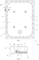
- Fig. 1 schematically illustrates a diaphragm filter plate assembly 10 according to an embodiment of the present disclosure, as seen from a diaphragm side thereof.
- the filter diaphragm 1 has been received by the diaphragm filter plate 5 such that the frame region 6 of the diaphragm filter plate 5 boundaries the filter diaphragm 1.
- a plurality of studs 3 are provided on the sealing region 4 of the diaphragm 1, spaced apart from each other along the sealing region 4. Pins 11 are inserted into the studs 3.
- Fig. 2 schematically illustrates a cross-sectional cut vied along line A-A of Fig. 1 .
- the sealing region 4 lies against the sealing surface 8 of the diaphragm filter plate 5, while the portion filter diaphragm body 2 delimited by the sealing region 4 is received by the web region 7 of the diaphragm filter plate 5.
- the studs 3 are inserted into corresponding holes 9 and pins 11 are inserted to the studs 3.
- pins 11 and studs 3 are hollow, pressure communication between the bottom of the hole 9 and the surrounding environment is allowed.
- a portion of increased diameter 3b is formed on the distal portion of the studs 3, corresponding to the undercut formed to the hole 9
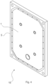
- Fig. 5 schematically illustrates a plate side, i.e. the facing the diaphragm filter plate to which it is attached when in use, of a filter diaphragm 1 according to an embodiment of the present disclosure, as seen as a perspective view.
- the sealing region 4 of the filter diaphragm 1 surrounds the remaining portion of the filter diaphragm body 2.
- a plurality of studs 3 protruding from the sealing region 4 are spaced apart from each other along said sealing region 4.
- Continuous closed beaded edges 2a are provided on the portion of the body 2 surrounded by the sealing region, for additional attachment between the filter diaphragm.
- the beaded edge 2a is receivable within the groove 7c discussed above in connection with Fig. 3 .
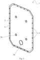
- Fig. 7 schematically illustrates a detailed view of a frame region 6, sealing plane 8 and a web region 7 of a diaphragm filter plate 5 of Fig 3 .
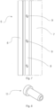
- Fig. 8 schematically illustrates a more detailed view of the pin 11., As can be seen, the hollow opening of the pin 11 extends to the bottom thereof.
Landscapes
- Chemical & Material Sciences (AREA)
- Chemical Kinetics & Catalysis (AREA)
- Filtration Of Liquid (AREA)
- Separation Using Semi-Permeable Membranes (AREA)
- Filtering Of Dispersed Particles In Gases (AREA)
- Diaphragms For Cameras (AREA)
Description
- The present disclosure relates to recessed plate -type filters, such as filter presses and tower presses, and more particularly to a filter diaphragm and a diaphragm filter plate assembly for such a filter. The present disclosure further concerns such a recessed plate -type filter itself.
- In a recessed plate -type filter, a diaphragm is used to squeeze remaining liquid content from a filter cake formed in a filter chamber. The diaphragm is typically attached to an associated filter plate either by ckamping it between the filter plate and a separate clamping component, or by providing the diaphragm and filter plate with a bead and groove, respectively.
- In cases where the diaphragm has been attached to the filter plate by clamping, the clamping component is typically secured with separate fasteners, such as bolts and clamps, which are susceptible to corrosion in typical filtration environments. Moreover, such attachment typically requires access to both sides of the filter plate, requiring the filter plate to be manipulated during installation.
- In cases where the diaphragm has been attached to the filter plate by inserting the bead of the diaphragm into a groove of the filter plate, the groove on the filter plate forms a discontinuity on the plate structure at an disadvantageous location, where a local maximum of internal stresses is exhibited. This has led to decreased longevity of the filter plate. Moreover, the bead and the groove form a pocket into which impurities entrained along with the compression medium used to pressurize the diaphragm may build-up or accumulate. This, in turn causes premature wear of the diaphragm.
- Publications
DE 19602977 C1 WO 03095063 A1 - An object of the present disclosure is to provide a recessed plate -type filter and a filter diaphragm and a diaphragm filter plate assembly for such a filter, which provide for improved longevity and facilitate installation.
- The object of the disclosure is achieved by the filter diaphragm, diaphragm filter plate assembly and a filter which characterized by what is stated in the independent claims. The preferred embodiments of the disclosure are disclosed in the dependent claims.
- The disclosure is based on the idea of providing filter diaphragm with studs, and the diaphragm filter late with corresponding holes, such that the diaphragm can be attached to the plate by inserting the studs into the holes.
- This provides multiple synergistic advantages. Firstly, the diaphragm can be attached ed to the plate from one side, thus removing the need to turn the heavy filter plate around during the attachment process.
- Moreover, the stud and opening can be formed on the diaphragm and plate, respectively, thus eliminating the need to use separate components such as metal nuts, bolts or bushing which are susceptible to corrosion.
- Additionally, using distinct, separate studs and holes, as opposed to a typical continuous bead inserted into a corresponding groove, provides a structure in which a pocket is not formed at the interface between the diaphragm and the plate (i.e. at the base of the bead). The lack of such a pocket prevents build-up or accumulation of impurities entrained along with the compression medium used to pressurize the diaphragm so as to squeeze the filter cake. Build- up or accumulation of such impurities is undesirable because it rubs against the diaphragm causing premature wear.
- Finaly, the solutions according to the present invention provide a structure in which a local maximum of internal stresses caused by an annular groove on the diaphragm filter plate is not exhibited.
- In the following the disclosure will be described in greater detail by means of preferred embodiments with reference to the accompanying drawings, in which
-
Fig. 1 schematically illustrates a diaphragm filter plate assembly according to an embodiment of the present disclosure, as seen from a diaphragm side thereof; -
Fig. 2 schematically illustrates a cross-sectional cut vied along line A-A ofFig. 1 ; -
Fig. 3 schematically illustrates a diaphragm side of a diaphragm filter plate according to an embodiment of the present disclosure, as seen as a perspective view; -
Fig. 4 schematically illustrates a diaphragm side of a diaphragm filter plate assembly according to an embodiment of the present disclosure, as seen as a perspective view; -
Fig. 5 schematically illustrates a plate side of a filter diaphragm according to an embodiment of the present disclosure, as seen as a perspective view; -
Fig. 6 schematically illustrates a chamber side of a filter diaphragm according to an embodiment of the present disclosure, as seen as a perspective view; -
Fig. 7 schematically illustrates a detailed view of a frame region, sealing plane and a web region of a diaphragm filter plate according to an embodiment of the present disclosure; and -
Fig. 8 schematically illustrates a pin of a diaphragm filter plate assembly according to an embodiment of the present disclosure. - According to a first aspect of the present disclosure, a
filter diaphragm 1 for afilter plate assembly 10 of a recessed plate -type filter is provided. Well known examples of such recessed plate -type filter include filter presses and tower presses. - The
filter diaphragm 1 comprises, comprising a sheet-like body 2 having a flexible structure. That is, the structure of thediaphragm body 2 is able to yield without permanent deformation so as the press a filter cake formed in a filter chamber of an associated filter. - Moreover, the
filter diaphragm 1 comprises, at least on a side of thebody 2, a plurality of distinct attachment studs 3 for being inserted into correspondingdistinct attachment holes 9 of arespective filter plate 5 for attaching thediaphragm 1 to thefilter plate 5. The attachment studs 3 are arranged along a sealingregion 4 extending along a periphery of thefilter diaphragm 1. Most suitably, the attachment studs 3 extend in a direction perpendicular to thediaphragm body 2. - Particularly, the attachment studs 3 are equipped with an opening 3a extending through the
filter diaphragm 1, between the opposing sides thereof. - This arrangement provides a structure that prevents the formation or build-up of impurities at the interface of the
filter diaphragm 2 and thediaphragm filter plate 5 without the need for separate attachment components that as susceptible to corrosion. At the same time, the opening (i.e. hollowness) of the stud enables pressure to equalize between the bottom of the associatedhole 9 and the surrounding environment, thus preventing the stud from being popped out of thehole 9, further ensuring secure attachment between thefilter diaphragm 2 and thefilter plate 5. - Preferably, but not necessarily, the
filter diaphragm 1 is suitable for aplate assembly 10 of a recessed plate -type filter, in which a collector duct for pressurizing a side of the diaphragm, so as to squeeze a filter cake, is sectionally formed by a plurality offilter plates 5 equipped with correspondingsectional openings 6a. The solution according to the present disclosure ais particularly advantageous in filters of such types, because contamination of impurities is a particularly prominent problem. This is because, the sectionally formed collector duct is opened each together with opening the filter chambers for discharging the filter cake. At this time impurities can readily contaminate the open duct. - Preferably, but not necessarily, at least the
body 2 of the filter diaphragm is of an elastic material, such as a synthetic elastomer or rubber. This facilitates in achieving a flexible structure of thediaphragm 1body 2. - In an embodiment according to the first aspect of the present disclosure a
portion 3b of increased diameter is formed on distal portions of the attachment studs 3. This further improves secure attachment of thediaphragm 1 to thediaphragm filter plate 5. Alternatively, the studs 3 may be formed between a proximal portion and the distal portion of the stud 3. - Preferably, but not necessarily, the
portion 3b of increased diameter is formed as an annular bulge. Alternatively, theportion 3b of increased diameter could be provided as on or more distinct projections, such as knobs. If a plurality of such distinct projections is provided, the projections are suitably spaced apart from each other along the periphery of the stud 3. - Preferably, but not necessarily, the plurality of attachment studs 3 are formed integral with the
diaphragm body 2. Alternatively, the studs 3 may be provided as separate parts, which are then pushed through the diaphragm body 3 so as to attach the separate studs 3 to thediaphragm body 2. - In an embodiment according to the first aspect of the present disclosure, the
sealing region 4 is formed as a bead at least partly surrounding the remaining portion of thediaphragm body 2. - Preferably, but not necessarily, the
sealing region 4 is integral with thediaphragm body 2. - In an embodiment according to the first aspect of the present disclosure, the surface of the
sealing region 4 is substantially flat in portions thereof where studs 3 or associatedopenings 3a are not present. That is, the general shape of thesealing region 4 is flat, while local deviations, having negligible contribution to the attachment between thefilter diapragm 1 and the associatediaphragm filter plate 5, are permitted. For example, in the context of the present disclosure, thesealing region 4 may be considered substantially flat, while being equipped with grooves or ribs for improving the sealing effect (i.e. increasing the surface contact pressure) of thesealing region 4. Should such grooves or ribs be provided, they may preferably be arranged as annularly extending along the sealingregion 4. - In an embodiment according to the first aspect of the present disclosure, the sealing
region 4 has an increased thickness with respect to non-elevated portions of the remainingdiaphragm body 2. It should be noted, however, that thediaphragm body 2 may be provided with elevated portions, such as protuberances, knobs or the like, which may have a local material thickness higher than that of the sealingregion 4. - It should be noted that the first aspect of the present disclosure encompasses any combination of one or more embodiments, or variants thereof, as discussed above.
- According to a second aspect of the present disclosure, a
diaphragm filter plate 5 for a diaphragmfilter plate assembly 10 of a recessed plate -type filter, such as a filter press or a tower press, is provided. - The
diaphragm filter plate 5 comprises aframe region 6 surrounding and having an increased thickness with respect to the remaining portion of thefilter plate 5. - The
diaphragm filter plate 5 further comprises, at least on a first surface of thediaphragm filter plate 5, aweb region 7 confined by, and recessed with respect to theframe region 7. - The
diaphragm filter plate 5 further comprises, a sealingplane 8 between theframe region 6 and theweb region 7. The sealingplane 8 surrounds theweb region 7 and is recessed with respect to theframe region 6. - Particularly, the sealing
plane 8 of thediaphragm filter plate 5 further comprises a plurality ofdistinct attachment holes 9 for receiving attachment studs 3 of afilter diaphragm 1, such as the one discussed in connection with the first aspect of the present disclosure. - Preferably, but not necessarily, the
holes 9 are blind holes, which provides for a higher structural strength of thediaphragm filte plate 5 at thehole 9, as compare to a through hole. - In an embodiment according to the second aspect of the present disclosure, the
frame region 6 is equipped with anopening 6a extending therethrough for forming a section of a collector duct suitable for pressurizing thefilter diaphragm 1, so as to squeeze a filter cake. - Suitably, the
opening 6a is in fluid communication with theweb region 7 via a conduit extending therebetween. - Moreover, opening 6a may be formed as an integral part of the
frame region 6, or alternatively, as a separate piece attached to the remainingframe portion 6. - In an embodiment according to the second aspect of the present disclosure, the sealing
plane 8 has a substantially flat surface for mating against a sealingregion 4 of thefilter diaphragm 1. That is, the general shape of the sealingplane 8 is flat, while local deviations, having negligible contribution to the attachment between thefilter diaphragm 1 and the associatediaphragm filter plate 5, are permitted. For example, in the context of the present disclosure, the sealingplane 8 may be considered substantially flat, while being equipped with grooves or ribs for improving the sealing effect (i.e. increasing the surface contact pressure) of the sealingplane 8. Should such grooves or ribs be provided, they may preferably be arranged as annularly extending along the sealingplane 8. - In an embodiment according to the second aspect of the present disclosure, the attachment holes 9 comprises an undercut. This further improves secure attachment of the
diaphragm 1 to thediaphragm filter plate 5. Preferably, such an undercut may be formed at the bottom of the associatedhole 9. Alternatively, the undercut be formed between a proximal portion and the distal portion of thehole 9. - Preferably, but not necessarily, the undercut is formed as an annular groove. Alternatively, the undercut could be provided as on or more distinct notches such as knobs. If a plurality of such distinct notches is provided, the notches are suitably spaced apart from each other along the inner circumference of the
hole 9. - It should be noted that the second aspect of the present disclosure encompasses any combination of one or more embodiments, or variants thereof, as discussed above.
- According to a third aspect of the present disclosure, a diaphragm
filter plate assembly 10 for a recessed plate -type filter, such as a filter press or a tower press, is provided. - The diaphragm
filter plate assembly 10 comprises thefilter diaphragm 1 according to the first aspect of the present disclosure, as discussed above, and thediaphragm filter plate 5 according to the second aspect of the present disclosure, as discussed above. - The
filter diaphragm 1 is received by thediaphragm filter plate 5 such that the sealingregion 4 is mated against the sealingplane 8 and the remaining portion of thediaphragm body 2 is received within theweb region 7 of thefilter plate 5 confined by the sealingplane 8. The attachment studs 3 of thefilter diaphragm 1 are received in the attachment holes 9. - In an embodiment according to the third aspect of the present disclosure, a plurality of
pins 11 are inserted intoopenings 3a of the attachment studs 3. - Preferably, but not necessarily,
such pins 11 are of a more rigid material than the studs. This arrangement further improves secure attachment between the filter diaphragm and thediaphragm filter plate 5. - Preferably, but not necessarily, the
pins 11 are hollow, which allows for equalizing pressure between the bottom of thehole 9, and the surrounding environment. - In an embodiment according to the third aspect of the present disclosure, the sealing
region 4 of thefilter diaphragm 1 is elevated from theframe region 6 of the diaphragm filter plate in an uncompressed state. This ensures that the sealingregion 4 is compressed when adjacent filter plates are pressed together to close the filter chamber. - In an embodiment according to the third aspect of the present disclosure, the
web region 7 of thediaphragm filter plate 5 comprises at least anelevated portion 7a having continuousclosed groove 7b, and whereinfilter diaphragm 1 comprises at least an continuous closedbeaded edge 2a, wherein thebeaded edge 2a is received within the groove 7c. Such an arrangement between thefilter diaphragm 1 and thediaphragm filter plate 5 at theweb region 7 of the latter further ensures secure attachment. Moreover, because thegroove 7b and thebeaded edge 2a do not confine thefilter diaphragm 1, a pocket is not formed, and the build-up of impurities is not considered to be negligible. - It should be noted that the third aspect of the present disclosure encompasses any combination of one or more embodiments, or variants thereof, as discussed above.
- According to a fourth aspect of the present disclosure, a recessed plate -type filter, such as a filter press or tower press, is provided.
- The filter comprises a plurality of diaphragm
filter plate assemblies 10 according to the third aspect of the disclosure, as discussed above. Moreover, the diaphragmfilter plate assemblies 10 are configured movable towards each other into a closed position in which a filter chamber is formed between adjacent diaphragm filter plate assemblies, and away from each to an open position in which adjacent diaphragm filter plate assemblies are spaced apart from each other. - The filter further comprises a filter medium arranged between adjacent diaphragm filter plate assemblies.
- The filter further comprises a translation arrangement for moving the diaphragm
filter plate assemblies 10 towards each other so as to form a filter chamber between adjacent filter plates, and away from each other so as to open the filter chamber. - The filter further comprises a feed arrangement for feeding slurry into the filter chamber.;
- The filter further comprises a recovering arrangement for recovering filtrate from the filter chamber.
- The filter further comprises a discharge arrangement for discharging a filter cake formed within the filter chamber.
- In an embodiment according to the fourth aspect of the present disclosure, the filter further comprises a plurality of chamber filter plate assemblies. In such a case, the diaphragm
filter plate assemblies 10 and the chamber filter plate assemblies are arranged in an alternating sequence so as to form the filter chamber between an adjacent diaphragmfilter plate assembly 10 and a chamber filter plate assembly. - In an embodiment according to the fourth aspect of the present disclosure, the filter comprises a compression arrangement for providing pressurized compression media on a side of the filter diaphragm opposite to the filter chamber.
- It should be noted that the fourth aspect of the present disclosure encompasses any combination of one or more embodiments, or variants thereof, as discussed above.
-
Fig. 1 schematically illustrates a diaphragmfilter plate assembly 10 according to an embodiment of the present disclosure, as seen from a diaphragm side thereof. Particularly, thefilter diaphragm 1 has been received by thediaphragm filter plate 5 such that theframe region 6 of thediaphragm filter plate 5 boundaries thefilter diaphragm 1. - A plurality of studs 3 are provided on the sealing
region 4 of thediaphragm 1, spaced apart from each other along the sealingregion 4.Pins 11 are inserted into the studs 3. -
Fig. 2 schematically illustrates a cross-sectional cut vied along line A-A ofFig. 1 . This more clearly illustrates the mutual engagement between thediaphragm 1 and thediaphragm filter plate 5. Particularly, the sealingregion 4 lies against the sealingsurface 8 of thediaphragm filter plate 5, while the portionfilter diaphragm body 2 delimited by the sealingregion 4 is received by theweb region 7 of thediaphragm filter plate 5. The studs 3 are inserted into correspondingholes 9 and pins 11 are inserted to the studs 3. As thepins 11 and studs 3 are hollow, pressure communication between the bottom of thehole 9 and the surrounding environment is allowed. A portion of increaseddiameter 3b is formed on the distal portion of the studs 3, corresponding to the undercut formed to thehole 9 -
Fig. 3 schematically illustrates a diaphragm side of adiaphragm filter plate 5 ofFig. 1 , without thediaphragm 1.Elevated portions 7a having a continuousclosed groove 7b, are provided on theweb portion 7, for providing additional attachment between thefilter diaphragm 1 and thediaphragm filter plate 5. -
Fig. 4 schematically illustrates the diaphragm side of a diaphragm filter plate assembly ofFig. 1 , as seen as a perspective view; -
Fig. 5 schematically illustrates a plate side, i.e. the facing the diaphragm filter plate to which it is attached when in use, of afilter diaphragm 1 according to an embodiment of the present disclosure, as seen as a perspective view. Particularly, the sealingregion 4 of thefilter diaphragm 1 surrounds the remaining portion of thefilter diaphragm body 2. A plurality of studs 3 protruding from the sealingregion 4 are spaced apart from each other along said sealingregion 4. Continuousclosed beaded edges 2a are provided on the portion of thebody 2 surrounded by the sealing region, for additional attachment between the filter diaphragm. Particularly, thebeaded edge 2a is receivable within the groove 7c discussed above in connection withFig. 3 . -
Fig. 6 schematically illustrates a chamber side, i.e. the opposing side, of the filter diaphragm ofFig. 5 , as seen as a perspective view; -
Fig. 7 schematically illustrates a detailed view of aframe region 6, sealingplane 8 and aweb region 7 of adiaphragm filter plate 5 ofFig 3 . -
Fig. 8 schematically illustrates a more detailed view of the pin 11., As can be seen, the hollow opening of thepin 11 extends to the bottom thereof. - Although the aspects and embodiments have been described above with reference a single sided diaphragm
filter plate assembly 10, i.e. an arrangement where thediaphragm 1 is only on one side of thediaphragm filter plate 5, it should be noted that the present disclosure encompasses arrangements in which afilter diaphragm 1 is provided on both sides of a diaphragm filter plate.
Claims (19)
- A filter diaphragm (1) for a filter plate assembly (10) of a recessed plate -type filter, such as a filter press or a tower press, comprising a sheet-like body (2) having a flexible structure,characterized by further comprising, at least on a side of the body (2), a plurality of distinct attachment studs (3) to be inserted into corresponding distinct attachment holes (9) of a respective filter plate (5) for attaching the diaphragm (1) to the filter plate (5),wherein the attachment studs (3) are arranged along a sealing region (4) extending along a periphery of the filter diaphragm (1), the sealing region being formed as a bead at least partly surrounding the remaining portion of the diaphragm body,wherein the attachment studs (3) extend in a direction perpendicular to the diaphragm body (2), andwherein the attachment studs (3) are equipped with an opening (3a) extending through the filter diaphragm (1), between the opposing sides thereof.
- A filter diaphragm (1) according to Claim 1, characterized in that the filter diaphragm (1) is suitable for a plate assembly (10) of a recessed plate -type filter, in which a collector duct for pressurizing a side of the diaphragm, so as to squeeze a filter cake, is sectionally formed by a plurality of filter plates (5) equipped with corresponding sectional openings (6a).
- The filter diaphragm according (1) to Claim 1 or 2, characterized in that at least the body (2) thereof is of an elastic material.
- The filter diaphragm according to any of the preceding Claims 1-3, characterized in that a portion (3b) of increased diameter is formed on distal portions of the attachment studs (3).
- The filter diaphragm (1) according to any of the preceding Claims 1-4, characterized in that the plurality of attachment studs (3) are formed integral with the diaphragm body (2).
- The filter diaphragm according to any of the preceding Claims 1-5, characterized in that the sealing region (4) is integral with the diaphragm body (2).
- The filter diaphragm (1) according to any of the preceding Claims, 1-6 the surface of the sealing region (4) is substantially flat in portions thereof where studs (3) or associated openings (3a) are not present.
- The filter diaphragm (1) according to any of the preceding Claims 1-7, characterized in that the sealing region (4) has an increased thickness with respect to non-elevated portions of the remaining diaphragm body (2).
- A diaphragm filter plate assembly (10) for a recessed plate -type filter, such as a filter press or a tower press, characterized by comprising the filter diaphragm (1) according to any of the preceding Claims 1-8, and a diaphragm filter plate (5) , the diaphragm filter plate (5), in turn, comprising:- a frame region (6) surrounding and having an increased thickness with respect to the remaining portion of the filter plate (5),- at least on a first surface of the diaphragm filter plate, a web region (7) confined by, and recessed with respect to the frame region, and- a sealing plane (8) between the frame region (6) and the web region (7), the sealing plane (8) surrounding the web region (7), and being recessed with respect to the frame region (6),wherein the sealing plane (8) of the diaphragm filter plate (5) further comprises a plurality of distinct attachment holes (9) for receiving attachment studs (3) of a filter diaphragm (1),wherein the filter diaphragm (1) is received by the diaphragm filter plate (5) such that the sealing region (4) is mated against the sealing plane (8) and the remaining portion of the diaphragm body (2) is received within the web region (7) of the filter plate (5) confined by the sealing plane (8), andwherein the attachment studs (3) of the filter diaphragm (1) are received in the attachment holes (9).
- The diaphragm filter plate assembly (10) according to Claim 9, characterized in that the frame (6) region is equipped with an opening (6a) extending therethrough for forming a section of a collector duct suitable for pressurizing the filter diaphragm (1), so as to squeeze a filter cake.
- The diaphragm filter plate assembly (10) according to Claim 9 or 10, characterized in that the sealing plane (8) has a substantially flat surface for mating against a sealing region (4) of the filter diaphragm (1).
- The diaphragm filter plate assembly (10) according to any of the preceding Claims 9-11, characterized in that the attachment holes (9) comprises an undercut .
- The diaphragm filter plate assembly (10) according to any of the preceding Claims 9-12, characterized by further comprising a plurality of pins (11) inserted into openings (3a) of the attachment studs (3).
- The diaphragm filter plate assembly (10) according to Claim 13, characterized in that the pins (11) are hollow.
- The diaphragm filter plate assembly according to any of the preceding Claims 9-14, characterized in that, in an uncompressed state, the sealing region (4) of the filter diaphragm (1) is elevated from the frame region (6) of the diaphragm filter plate.
- The diaphragm filter plate assembly (10) according to any of the preceding Claims 9-15, characterized in that the web region (7) of the diaphragm filter plate (5) comprises at least an elevated portion (7a) having continuous closed groove (7b), and wherein filter diaphragm (1) comprises at least an continuous closed beaded edge (2a), wherein the beaded edge (2a) is received within the groove (7c).
- A recessed plate -type filter, such as a filter press or tower press, characterized in that the filter comprises:a plurality of diaphragm filter plate assemblies (10) according to any of the preceding Claims 9-16, wherein the diaphragm filter plate assemblies (10) are configured movable towards each other into a closed position in which a filter chamber is formed between adjacent diaphragm filter plate assemblies, and away from each to an open position in which adjacent diaphragm filter plate assemblies are spaced apart from each other;a filter medium arranged between adjacent diaphragm filter plate assemblies;a translation arrangement for moving the diaphragm filter plate assemblies towards each other so as to form a filter chamber between adjacent filter plates, and away from each other so as to open the filter chamber;a feed arrangement for feeding slurry into the filter chamber;a recovering arrangement for recovering filtrate from the filter chamber, anda discharge arrangement for discharging a filter cake formed within the filter chamber.
- The recessed plate -type filter, filter according to Claim 17, characterized by further comprising a plurality of chamber filter plate assemblies, wherein the diaphragm filter plate assemblies (10) and the chamber filter plate assemblies are arranged in an alternating sequence so as to form the filter chamber between an adjacent diaphragm filter plate assembly (10) and a chamber filter plate assembly.
- The recessed plate -type filter, filter according to Claim 17 or 18, characterized by further comprising a compression arrangement for providing pressurized compression media on a side of the filter diaphragm opposite to the filter chamber.
Priority Applications (2)
| Application Number | Priority Date | Filing Date | Title |
|---|---|---|---|
| EP24158992.8A EP4349447B1 (en) | 2020-02-07 | 2020-02-07 | A filter diaphragm for a recessed plate -type filter, a diaphragm filter plate, a diaphragm filer plate assembly and a recessed plate -type filter |
| PT241589928T PT4349447T (en) | 2020-02-07 | 2020-02-07 | A filter diaphragm for a recessed plate -type filter, a diaphragm filter plate, a diaphragm filer plate assembly and a recessed plate -type filter |
Applications Claiming Priority (1)
| Application Number | Priority Date | Filing Date | Title |
|---|---|---|---|
| PCT/FI2020/050076 WO2021156536A1 (en) | 2020-02-07 | 2020-02-07 | A filter diaphragm for a recessed plate -type filter, a diaphragm filter plate, a diaphragm filter plate assembly and a recessed plate -type filter |
Related Child Applications (2)
| Application Number | Title | Priority Date | Filing Date |
|---|---|---|---|
| EP24158992.8A Division EP4349447B1 (en) | 2020-02-07 | 2020-02-07 | A filter diaphragm for a recessed plate -type filter, a diaphragm filter plate, a diaphragm filer plate assembly and a recessed plate -type filter |
| EP24158992.8A Division-Into EP4349447B1 (en) | 2020-02-07 | 2020-02-07 | A filter diaphragm for a recessed plate -type filter, a diaphragm filter plate, a diaphragm filer plate assembly and a recessed plate -type filter |
Publications (3)
| Publication Number | Publication Date |
|---|---|
| EP4100143A1 EP4100143A1 (en) | 2022-12-14 |
| EP4100143A4 EP4100143A4 (en) | 2023-09-06 |
| EP4100143B1 true EP4100143B1 (en) | 2025-04-09 |
Family
ID=77180915
Family Applications (2)
| Application Number | Title | Priority Date | Filing Date |
|---|---|---|---|
| EP24158992.8A Active EP4349447B1 (en) | 2020-02-07 | 2020-02-07 | A filter diaphragm for a recessed plate -type filter, a diaphragm filter plate, a diaphragm filer plate assembly and a recessed plate -type filter |
| EP20918116.3A Active EP4100143B1 (en) | 2020-02-07 | 2020-02-07 | A filter diaphragm for a recessed plate -type filter, a diaphragm filter plate assembly and a recessed plate -type filter |
Family Applications Before (1)
| Application Number | Title | Priority Date | Filing Date |
|---|---|---|---|
| EP24158992.8A Active EP4349447B1 (en) | 2020-02-07 | 2020-02-07 | A filter diaphragm for a recessed plate -type filter, a diaphragm filter plate, a diaphragm filer plate assembly and a recessed plate -type filter |
Country Status (11)
| Country | Link |
|---|---|
| US (2) | US12447422B2 (en) |
| EP (2) | EP4349447B1 (en) |
| CN (2) | CN113244670B (en) |
| AU (1) | AU2020427260A1 (en) |
| CA (1) | CA3168851A1 (en) |
| ES (2) | ES3059637T3 (en) |
| FI (2) | FI4349447T3 (en) |
| MX (1) | MX2022009322A (en) |
| PL (2) | PL4100143T3 (en) |
| PT (2) | PT4100143T (en) |
| WO (1) | WO2021156536A1 (en) |
Families Citing this family (2)
| Publication number | Priority date | Publication date | Assignee | Title |
|---|---|---|---|---|
| PL4100143T3 (en) * | 2020-02-07 | 2025-08-04 | Metso Finland Oy | A filter diaphragm for a recessed plate -type filter, a diaphragm filter plate assembly and a recessed plate -type filter |
| WO2023021439A1 (en) * | 2021-08-17 | 2023-02-23 | Flsmidth A/S | Modular filter plate assembly for horizontal filter presses |
Family Cites Families (8)
| Publication number | Priority date | Publication date | Assignee | Title |
|---|---|---|---|---|
| DK140383B (en) * | 1974-02-06 | 1979-08-13 | Per Topholm | Expansion dowel. |
| DE3577043D1 (en) * | 1984-01-31 | 1990-05-17 | Jv Kunststoffwerk | MEMBRANE FILTER PLATE. |
| DE10221061B4 (en) * | 2002-05-10 | 2006-03-09 | Jvk Filtration Systems Gmbh | Membrane, membrane plate and plate pack for a filter press |
| DE19602977C1 (en) * | 1996-01-27 | 1997-02-13 | Lenser Kunststoff Preswerk Gmb | Membrane filter plate for a filter press |
| KR100541328B1 (en) * | 2002-12-30 | 2006-01-11 | 가부시키가이샤 이시가키 | Filter press |
| DE102012209591B4 (en) * | 2012-06-06 | 2021-03-04 | Strassburger Filter Gmbh & Co. Kg | Membrane plate, filter plate, filter press and using a filter press |
| CN205360711U (en) * | 2015-12-23 | 2016-07-06 | 上海艾思其工程技术有限公司 | Filter plate diaphragm of pressure filter |
| PL4100143T3 (en) * | 2020-02-07 | 2025-08-04 | Metso Finland Oy | A filter diaphragm for a recessed plate -type filter, a diaphragm filter plate assembly and a recessed plate -type filter |
-
2020
- 2020-02-07 PL PL20918116.3T patent/PL4100143T3/en unknown
- 2020-02-07 ES ES24158992T patent/ES3059637T3/en active Active
- 2020-02-07 MX MX2022009322A patent/MX2022009322A/en unknown
- 2020-02-07 US US17/797,018 patent/US12447422B2/en active Active
- 2020-02-07 CA CA3168851A patent/CA3168851A1/en active Pending
- 2020-02-07 EP EP24158992.8A patent/EP4349447B1/en active Active
- 2020-02-07 FI FIEP24158992.8T patent/FI4349447T3/en active
- 2020-02-07 AU AU2020427260A patent/AU2020427260A1/en active Pending
- 2020-02-07 EP EP20918116.3A patent/EP4100143B1/en active Active
- 2020-02-07 PL PL24158992.8T patent/PL4349447T3/en unknown
- 2020-02-07 PT PT209181163T patent/PT4100143T/en unknown
- 2020-02-07 FI FIEP20918116.3T patent/FI4100143T3/en active
- 2020-02-07 PT PT241589928T patent/PT4349447T/en unknown
- 2020-02-07 ES ES20918116T patent/ES3035150T3/en active Active
- 2020-02-07 WO PCT/FI2020/050076 patent/WO2021156536A1/en not_active Ceased
-
2021
- 2021-02-08 CN CN202110172319.2A patent/CN113244670B/en active Active
- 2021-02-08 CN CN202120355085.0U patent/CN216934847U/en active Active
-
2025
- 2025-09-19 US US19/333,626 patent/US20260014496A1/en active Pending
Also Published As
| Publication number | Publication date |
|---|---|
| CN113244670A (en) | 2021-08-13 |
| BR112022015133A2 (en) | 2022-10-11 |
| EP4349447A3 (en) | 2024-05-29 |
| ES3035150T3 (en) | 2025-08-29 |
| PT4349447T (en) | 2025-11-26 |
| PL4100143T3 (en) | 2025-08-04 |
| PL4349447T3 (en) | 2026-03-23 |
| CN113244670B (en) | 2025-09-16 |
| CA3168851A1 (en) | 2021-08-12 |
| US20260014496A1 (en) | 2026-01-15 |
| EP4100143A1 (en) | 2022-12-14 |
| ES3059637T3 (en) | 2026-03-23 |
| EP4100143A4 (en) | 2023-09-06 |
| WO2021156536A1 (en) | 2021-08-12 |
| EP4349447A2 (en) | 2024-04-10 |
| AU2020427260A1 (en) | 2022-08-18 |
| MX2022009322A (en) | 2022-08-22 |
| FI4349447T3 (en) | 2025-12-12 |
| EP4349447B1 (en) | 2025-11-12 |
| CN216934847U (en) | 2022-07-12 |
| US12447422B2 (en) | 2025-10-21 |
| PT4100143T (en) | 2025-05-06 |
| US20230064222A1 (en) | 2023-03-02 |
| FI4100143T3 (en) | 2025-07-03 |
Similar Documents
| Publication | Publication Date | Title |
|---|---|---|
| US20260014496A1 (en) | Diaphragm filter plate for a recessed plate -type filter | |
| US4608164A (en) | Membrane filter plate | |
| JP4543406B2 (en) | Die blade holding device and die assembly | |
| EP2156873A1 (en) | Filter element, securing ring and method for filtering | |
| US5484526A (en) | Membrane plate for plate filter presses | |
| US5603827A (en) | Membrane filter plate | |
| US4826593A (en) | Membrane filter press | |
| US20230055796A1 (en) | An outlet cover for a recessed plate-type filter, a filter plate, a filter plate assembly and a recessed plate-type filter | |
| JP2004538412A (en) | Oil filter mounting plate assembly | |
| EP4267272B1 (en) | Filtrate vat assembly for a filter press | |
| JPH05103914A (en) | Compression plate and compression membrane for filter press | |
| US10399009B2 (en) | Filling shoe, a filling shoe arrangement having such a filling shoe, a filter medium assembly having such filling shoe arrangements, and a method for providing a filter medium with such a filling shoe | |
| EP0579103A2 (en) | Stabilizing structure for use with a filter press plate | |
| WO2000045936A1 (en) | Housing assembly for mounting an industrial oil filter assembly | |
| CN211533893U (en) | Sealing ring assembly for cooking appliance, pot cover and cooking appliance | |
| JPH0721104U (en) | Squeeze filter plate in squeeze filter press | |
| JP4937315B2 (en) | Filter frame in filter press | |
| EP4135869B1 (en) | A sealing strip for sealing adjacent filter plate assemblies of a filter press, such as a tower press, a filter frame, a filter frame assembly and a filter apparatus | |
| BR112022015133B1 (en) | A filter diaphragm for a recessed plate type filter, a diaphragm filter plate, a diaphragm filter plate assembly, and a recessed plate type filter. | |
| JPH063405U (en) | Liquid leak prevention structure for filter cloth | |
| CN118059553A (en) | Filter pressing plate with anti-drop function for filter press | |
| SK9757Y1 (en) | Filter membrane, plate frame, plate frame assembly, grooving or milling tool assembly and horizontal filter press | |
| GB2153248A (en) | Filter press plate assembly | |
| JPH024797Y2 (en) | ||
| JPH03202105A (en) | Filter plate structure of filter press |
Legal Events
| Date | Code | Title | Description |
|---|---|---|---|
| STAA | Information on the status of an ep patent application or granted ep patent |
Free format text: STATUS: THE INTERNATIONAL PUBLICATION HAS BEEN MADE |
|
| PUAI | Public reference made under article 153(3) epc to a published international application that has entered the european phase |
Free format text: ORIGINAL CODE: 0009012 |
|
| STAA | Information on the status of an ep patent application or granted ep patent |
Free format text: STATUS: REQUEST FOR EXAMINATION WAS MADE |
|
| 17P | Request for examination filed |
Effective date: 20220714 |
|
| AK | Designated contracting states |
Kind code of ref document: A1 Designated state(s): AL AT BE BG CH CY CZ DE DK EE ES FI FR GB GR HR HU IE IS IT LI LT LU LV MC MK MT NL NO PL PT RO RS SE SI SK SM TR |
|
| DAV | Request for validation of the european patent (deleted) | ||
| DAX | Request for extension of the european patent (deleted) | ||
| P01 | Opt-out of the competence of the unified patent court (upc) registered |
Effective date: 20230627 |
|
| A4 | Supplementary search report drawn up and despatched |
Effective date: 20230803 |
|
| RIC1 | Information provided on ipc code assigned before grant |
Ipc: B01D 25/12 20060101ALI20230728BHEP Ipc: B01D 25/133 20060101AFI20230728BHEP |
|
| RAP3 | Party data changed (applicant data changed or rights of an application transferred) |
Owner name: METSO FINLAND OY |
|
| GRAP | Despatch of communication of intention to grant a patent |
Free format text: ORIGINAL CODE: EPIDOSNIGR1 |
|
| STAA | Information on the status of an ep patent application or granted ep patent |
Free format text: STATUS: GRANT OF PATENT IS INTENDED |
|
| INTG | Intention to grant announced |
Effective date: 20241209 |
|
| GRAS | Grant fee paid |
Free format text: ORIGINAL CODE: EPIDOSNIGR3 |
|
| GRAA | (expected) grant |
Free format text: ORIGINAL CODE: 0009210 |
|
| STAA | Information on the status of an ep patent application or granted ep patent |
Free format text: STATUS: THE PATENT HAS BEEN GRANTED |
|
| AK | Designated contracting states |
Kind code of ref document: B1 Designated state(s): AL AT BE BG CH CY CZ DE DK EE ES FI FR GB GR HR HU IE IS IT LI LT LU LV MC MK MT NL NO PL PT RO RS SE SI SK SM TR |
|
| REG | Reference to a national code |
Ref country code: GB Ref legal event code: FG4D |
|
| REG | Reference to a national code |
Ref country code: CH Ref legal event code: EP |
|
| REG | Reference to a national code |
Ref country code: DE Ref legal event code: R096 Ref document number: 602020049346 Country of ref document: DE |
|
| REG | Reference to a national code |
Ref country code: PT Ref legal event code: SC4A Ref document number: 4100143 Country of ref document: PT Date of ref document: 20250506 Kind code of ref document: T Free format text: AVAILABILITY OF NATIONAL TRANSLATION Effective date: 20250429 |
|
| REG | Reference to a national code |
Ref country code: IE Ref legal event code: FG4D |
|
| REG | Reference to a national code |
Ref country code: SE Ref legal event code: TRGR |
|
| REG | Reference to a national code |
Ref country code: NL Ref legal event code: FP |
|
| REG | Reference to a national code |
Ref country code: FI Ref legal event code: FGE |
|
| REG | Reference to a national code |
Ref country code: GR Ref legal event code: EP Ref document number: 20250401295 Country of ref document: GR Effective date: 20250707 |
|
| REG | Reference to a national code |
Ref country code: ES Ref legal event code: FG2A Ref document number: 3035150 Country of ref document: ES Kind code of ref document: T3 Effective date: 20250829 |
|
| REG | Reference to a national code |
Ref country code: LT Ref legal event code: MG9D |
|
| PG25 | Lapsed in a contracting state [announced via postgrant information from national office to epo] |
Ref country code: NO Free format text: LAPSE BECAUSE OF FAILURE TO SUBMIT A TRANSLATION OF THE DESCRIPTION OR TO PAY THE FEE WITHIN THE PRESCRIBED TIME-LIMIT Effective date: 20250709 |
|
| PG25 | Lapsed in a contracting state [announced via postgrant information from national office to epo] |
Ref country code: BG Free format text: LAPSE BECAUSE OF FAILURE TO SUBMIT A TRANSLATION OF THE DESCRIPTION OR TO PAY THE FEE WITHIN THE PRESCRIBED TIME-LIMIT Effective date: 20250409 |
|
| PG25 | Lapsed in a contracting state [announced via postgrant information from national office to epo] |
Ref country code: HR Free format text: LAPSE BECAUSE OF FAILURE TO SUBMIT A TRANSLATION OF THE DESCRIPTION OR TO PAY THE FEE WITHIN THE PRESCRIBED TIME-LIMIT Effective date: 20250409 |
|
| PG25 | Lapsed in a contracting state [announced via postgrant information from national office to epo] |
Ref country code: RS Free format text: LAPSE BECAUSE OF FAILURE TO SUBMIT A TRANSLATION OF THE DESCRIPTION OR TO PAY THE FEE WITHIN THE PRESCRIBED TIME-LIMIT Effective date: 20250709 |
|
| PG25 | Lapsed in a contracting state [announced via postgrant information from national office to epo] |
Ref country code: IS Free format text: LAPSE BECAUSE OF FAILURE TO SUBMIT A TRANSLATION OF THE DESCRIPTION OR TO PAY THE FEE WITHIN THE PRESCRIBED TIME-LIMIT Effective date: 20250809 |
|
| PG25 | Lapsed in a contracting state [announced via postgrant information from national office to epo] |
Ref country code: LV Free format text: LAPSE BECAUSE OF FAILURE TO SUBMIT A TRANSLATION OF THE DESCRIPTION OR TO PAY THE FEE WITHIN THE PRESCRIBED TIME-LIMIT Effective date: 20250409 |
|
| REG | Reference to a national code |
Ref country code: DE Ref legal event code: R097 Ref document number: 602020049346 Country of ref document: DE |
|
| PG25 | Lapsed in a contracting state [announced via postgrant information from national office to epo] |
Ref country code: DK Free format text: LAPSE BECAUSE OF FAILURE TO SUBMIT A TRANSLATION OF THE DESCRIPTION OR TO PAY THE FEE WITHIN THE PRESCRIBED TIME-LIMIT Effective date: 20250409 Ref country code: SM Free format text: LAPSE BECAUSE OF FAILURE TO SUBMIT A TRANSLATION OF THE DESCRIPTION OR TO PAY THE FEE WITHIN THE PRESCRIBED TIME-LIMIT Effective date: 20250409 |
|
| PG25 | Lapsed in a contracting state [announced via postgrant information from national office to epo] |
Ref country code: EE Free format text: LAPSE BECAUSE OF FAILURE TO SUBMIT A TRANSLATION OF THE DESCRIPTION OR TO PAY THE FEE WITHIN THE PRESCRIBED TIME-LIMIT Effective date: 20250409 |
|
| PG25 | Lapsed in a contracting state [announced via postgrant information from national office to epo] |
Ref country code: SK Free format text: LAPSE BECAUSE OF FAILURE TO SUBMIT A TRANSLATION OF THE DESCRIPTION OR TO PAY THE FEE WITHIN THE PRESCRIBED TIME-LIMIT Effective date: 20250409 |
|
| PLBE | No opposition filed within time limit |
Free format text: ORIGINAL CODE: 0009261 |
|
| STAA | Information on the status of an ep patent application or granted ep patent |
Free format text: STATUS: NO OPPOSITION FILED WITHIN TIME LIMIT |
|
| PGFP | Annual fee paid to national office [announced via postgrant information from national office to epo] |
Ref country code: NL Payment date: 20260106 Year of fee payment: 7 |
|
| REG | Reference to a national code |
Ref country code: CH Ref legal event code: L10 Free format text: ST27 STATUS EVENT CODE: U-0-0-L10-L00 (AS PROVIDED BY THE NATIONAL OFFICE) Effective date: 20260218 |
|
| 26N | No opposition filed |
Effective date: 20260112 |
|
| PGFP | Annual fee paid to national office [announced via postgrant information from national office to epo] |
Ref country code: SE Payment date: 20260105 Year of fee payment: 7 |
|
| PGFP | Annual fee paid to national office [announced via postgrant information from national office to epo] |
Ref country code: ES Payment date: 20260310 Year of fee payment: 7 |
|
| PGFP | Annual fee paid to national office [announced via postgrant information from national office to epo] |
Ref country code: DE Payment date: 20260102 Year of fee payment: 7 |
|
| PGFP | Annual fee paid to national office [announced via postgrant information from national office to epo] |
Ref country code: AT Payment date: 20260127 Year of fee payment: 7 |
|
| PGFP | Annual fee paid to national office [announced via postgrant information from national office to epo] |
Ref country code: FI Payment date: 20260213 Year of fee payment: 7 Ref country code: IT Payment date: 20260122 Year of fee payment: 7 |
|
| PGFP | Annual fee paid to national office [announced via postgrant information from national office to epo] |
Ref country code: TR Payment date: 20260206 Year of fee payment: 7 |
|
| PGFP | Annual fee paid to national office [announced via postgrant information from national office to epo] |
Ref country code: PT Payment date: 20260202 Year of fee payment: 7 Ref country code: CZ Payment date: 20260119 Year of fee payment: 7 |
|
| PGFP | Annual fee paid to national office [announced via postgrant information from national office to epo] |
Ref country code: GR Payment date: 20260114 Year of fee payment: 7 Ref country code: PL Payment date: 20260112 Year of fee payment: 7 |