EP4099666A1 - Electronic assembly and electronic device - Google Patents
Electronic assembly and electronic device Download PDFInfo
- Publication number
- EP4099666A1 EP4099666A1 EP21795586.3A EP21795586A EP4099666A1 EP 4099666 A1 EP4099666 A1 EP 4099666A1 EP 21795586 A EP21795586 A EP 21795586A EP 4099666 A1 EP4099666 A1 EP 4099666A1
- Authority
- EP
- European Patent Office
- Prior art keywords
- rotating member
- rotating
- electronic assembly
- gear
- shaft case
- Prior art date
- Legal status (The legal status is an assumption and is not a legal conclusion. Google has not performed a legal analysis and makes no representation as to the accuracy of the status listed.)
- Granted
Links
Images












Classifications
-
- H—ELECTRICITY
- H04—ELECTRIC COMMUNICATION TECHNIQUE
- H04M—TELEPHONIC COMMUNICATION
- H04M1/00—Substation equipment, e.g. for use by subscribers
- H04M1/02—Constructional features of telephone sets
- H04M1/0202—Portable telephone sets, e.g. cordless phones, mobile phones or bar type handsets
- H04M1/0206—Portable telephones comprising a plurality of mechanically joined movable body parts, e.g. hinged housings
- H04M1/0208—Portable telephones comprising a plurality of mechanically joined movable body parts, e.g. hinged housings characterized by the relative motions of the body parts
- H04M1/0214—Foldable telephones, i.e. with body parts pivoting to an open position around an axis parallel to the plane they define in closed position
- H04M1/0216—Foldable in one direction, i.e. using a one degree of freedom hinge
-
- H—ELECTRICITY
- H05—ELECTRIC TECHNIQUES NOT OTHERWISE PROVIDED FOR
- H05K—PRINTED CIRCUITS; CASINGS OR CONSTRUCTIONAL DETAILS OF ELECTRIC APPARATUS; MANUFACTURE OF ASSEMBLAGES OF ELECTRICAL COMPONENTS
- H05K5/00—Casings, cabinets or drawers for electric apparatus
- H05K5/02—Details
- H05K5/0217—Mechanical details of casings
- H05K5/0226—Hinges
-
- G—PHYSICS
- G06—COMPUTING OR CALCULATING; COUNTING
- G06F—ELECTRIC DIGITAL DATA PROCESSING
- G06F1/00—Details not covered by groups G06F3/00 - G06F13/00 and G06F21/00
- G06F1/16—Constructional details or arrangements
- G06F1/1613—Constructional details or arrangements for portable computers
- G06F1/1633—Constructional details or arrangements of portable computers not specific to the type of enclosures covered by groups G06F1/1615 - G06F1/1626
- G06F1/1637—Details related to the display arrangement, including those related to the mounting of the display in the housing
- G06F1/1652—Details related to the display arrangement, including those related to the mounting of the display in the housing the display being flexible, e.g. mimicking a sheet of paper, or rollable
-
- F—MECHANICAL ENGINEERING; LIGHTING; HEATING; WEAPONS; BLASTING
- F16—ENGINEERING ELEMENTS AND UNITS; GENERAL MEASURES FOR PRODUCING AND MAINTAINING EFFECTIVE FUNCTIONING OF MACHINES OR INSTALLATIONS; THERMAL INSULATION IN GENERAL
- F16C—SHAFTS; FLEXIBLE SHAFTS; ELEMENTS OR CRANKSHAFT MECHANISMS; ROTARY BODIES OTHER THAN GEARING ELEMENTS; BEARINGS
- F16C11/00—Pivots; Pivotal connections
- F16C11/04—Pivotal connections
-
- F—MECHANICAL ENGINEERING; LIGHTING; HEATING; WEAPONS; BLASTING
- F16—ENGINEERING ELEMENTS AND UNITS; GENERAL MEASURES FOR PRODUCING AND MAINTAINING EFFECTIVE FUNCTIONING OF MACHINES OR INSTALLATIONS; THERMAL INSULATION IN GENERAL
- F16C—SHAFTS; FLEXIBLE SHAFTS; ELEMENTS OR CRANKSHAFT MECHANISMS; ROTARY BODIES OTHER THAN GEARING ELEMENTS; BEARINGS
- F16C11/00—Pivots; Pivotal connections
- F16C11/04—Pivotal connections
- F16C11/10—Arrangements for locking
-
- G—PHYSICS
- G06—COMPUTING OR CALCULATING; COUNTING
- G06F—ELECTRIC DIGITAL DATA PROCESSING
- G06F1/00—Details not covered by groups G06F3/00 - G06F13/00 and G06F21/00
- G06F1/16—Constructional details or arrangements
- G06F1/1613—Constructional details or arrangements for portable computers
- G06F1/1633—Constructional details or arrangements of portable computers not specific to the type of enclosures covered by groups G06F1/1615 - G06F1/1626
- G06F1/1675—Miscellaneous details related to the relative movement between the different enclosures or enclosure parts
- G06F1/1681—Details related solely to hinges
-
- G—PHYSICS
- G09—EDUCATION; CRYPTOGRAPHY; DISPLAY; ADVERTISING; SEALS
- G09F—DISPLAYING; ADVERTISING; SIGNS; LABELS OR NAME-PLATES; SEALS
- G09F9/00—Indicating arrangements for variable information in which the information is built-up on a support by selection or combination of individual elements
- G09F9/30—Indicating arrangements for variable information in which the information is built-up on a support by selection or combination of individual elements in which the desired character or characters are formed by combining individual elements
- G09F9/301—Indicating arrangements for variable information in which the information is built-up on a support by selection or combination of individual elements in which the desired character or characters are formed by combining individual elements flexible foldable or roll-able electronic displays, e.g. thin LCD, OLED
-
- H—ELECTRICITY
- H04—ELECTRIC COMMUNICATION TECHNIQUE
- H04M—TELEPHONIC COMMUNICATION
- H04M1/00—Substation equipment, e.g. for use by subscribers
- H04M1/02—Constructional features of telephone sets
- H04M1/0202—Portable telephone sets, e.g. cordless phones, mobile phones or bar type handsets
- H04M1/0206—Portable telephones comprising a plurality of mechanically joined movable body parts, e.g. hinged housings
- H04M1/0208—Portable telephones comprising a plurality of mechanically joined movable body parts, e.g. hinged housings characterized by the relative motions of the body parts
- H04M1/0214—Foldable telephones, i.e. with body parts pivoting to an open position around an axis parallel to the plane they define in closed position
-
- H—ELECTRICITY
- H04—ELECTRIC COMMUNICATION TECHNIQUE
- H04M—TELEPHONIC COMMUNICATION
- H04M1/00—Substation equipment, e.g. for use by subscribers
- H04M1/02—Constructional features of telephone sets
- H04M1/0202—Portable telephone sets, e.g. cordless phones, mobile phones or bar type handsets
- H04M1/0206—Portable telephones comprising a plurality of mechanically joined movable body parts, e.g. hinged housings
- H04M1/0208—Portable telephones comprising a plurality of mechanically joined movable body parts, e.g. hinged housings characterized by the relative motions of the body parts
- H04M1/0214—Foldable telephones, i.e. with body parts pivoting to an open position around an axis parallel to the plane they define in closed position
- H04M1/0216—Foldable in one direction, i.e. using a one degree of freedom hinge
- H04M1/022—The hinge comprising two parallel pivoting axes
-
- H—ELECTRICITY
- H04—ELECTRIC COMMUNICATION TECHNIQUE
- H04M—TELEPHONIC COMMUNICATION
- H04M1/00—Substation equipment, e.g. for use by subscribers
- H04M1/02—Constructional features of telephone sets
- H04M1/0202—Portable telephone sets, e.g. cordless phones, mobile phones or bar type handsets
- H04M1/026—Details of the structure or mounting of specific components
- H04M1/0266—Details of the structure or mounting of specific components for a display module assembly
- H04M1/0268—Details of the structure or mounting of specific components for a display module assembly including a flexible display panel
-
- E—FIXED CONSTRUCTIONS
- E05—LOCKS; KEYS; WINDOW OR DOOR FITTINGS; SAFES
- E05D—HINGES OR SUSPENSION DEVICES FOR DOORS, WINDOWS OR WINGS
- E05D3/00—Hinges with pins
- E05D3/06—Hinges with pins with two or more pins
- E05D3/12—Hinges with pins with two or more pins with two parallel pins and one arm
- E05D3/122—Gear hinges
-
- E—FIXED CONSTRUCTIONS
- E05—LOCKS; KEYS; WINDOW OR DOOR FITTINGS; SAFES
- E05Y—INDEXING SCHEME ASSOCIATED WITH SUBCLASSES E05D AND E05F, RELATING TO CONSTRUCTION ELEMENTS, ELECTRIC CONTROL, POWER SUPPLY, POWER SIGNAL OR TRANSMISSION, USER INTERFACES, MOUNTING OR COUPLING, DETAILS, ACCESSORIES, AUXILIARY OPERATIONS NOT OTHERWISE PROVIDED FOR, APPLICATION THEREOF
- E05Y2999/00—Subject-matter not otherwise provided for in this subclass
-
- F—MECHANICAL ENGINEERING; LIGHTING; HEATING; WEAPONS; BLASTING
- F16—ENGINEERING ELEMENTS AND UNITS; GENERAL MEASURES FOR PRODUCING AND MAINTAINING EFFECTIVE FUNCTIONING OF MACHINES OR INSTALLATIONS; THERMAL INSULATION IN GENERAL
- F16C—SHAFTS; FLEXIBLE SHAFTS; ELEMENTS OR CRANKSHAFT MECHANISMS; ROTARY BODIES OTHER THAN GEARING ELEMENTS; BEARINGS
- F16C2370/00—Apparatus relating to physics, e.g. instruments
-
- F—MECHANICAL ENGINEERING; LIGHTING; HEATING; WEAPONS; BLASTING
- F16—ENGINEERING ELEMENTS AND UNITS; GENERAL MEASURES FOR PRODUCING AND MAINTAINING EFFECTIVE FUNCTIONING OF MACHINES OR INSTALLATIONS; THERMAL INSULATION IN GENERAL
- F16C—SHAFTS; FLEXIBLE SHAFTS; ELEMENTS OR CRANKSHAFT MECHANISMS; ROTARY BODIES OTHER THAN GEARING ELEMENTS; BEARINGS
- F16C2380/00—Electrical apparatus
Definitions
- This application relates to the technical field of electronic products, and in particular, to an electronic assembly and an electronic device.
- a shaft assembly is one of important structural components to control rotation of the electronic device.
- a current shaft assembly is relatively complex in structure, which increases total gaps, thus displacements after falling are enlarged, and a quality of the shaft assembly is declined.
- an electronic assembly in a first aspect of the disclosure, includes a shaft assembly and housings arranged oppositely.
- the shaft assembly includes a first shaft case, first rotating members, and rotating units.
- the housings are at least partially disposed at two opposite sides of the first shaft case.
- the first rotating members are at least partially disposed at the two opposite sides of the first shaft case.
- Each of the first rotating members has one end rotatably connected with the first shaft case and the other end connected with the housings.
- the rotating units are at least partially disposed at the two opposite sides of the first shaft case.
- Each of the rotating units includes a second rotating member and a movable plate.
- the second rotating member has one end rotatably connected with the first shaft case and the other end connected with the movable plate.
- the movable plate has one end connected to the housings.
- an electronic device in a second aspect of the disclosure, includes a flexible screen and the electronic assembly provided in the first aspect of the disclosure.
- the flexible screen is mounted on the movable plate of the electronic assembly.
- the electronic assembly includes a shaft assembly and housings arranged oppositely.
- the shaft assembly includes a first shaft case, first rotating members, and rotating units.
- the housings are at least partially disposed at two opposite sides of the first shaft case.
- the first rotating members are at least partially disposed at the two opposite sides of the first shaft case.
- Each of the first rotating members has one end rotatably connected with the first shaft case and the other end connected with the housings.
- the rotating units are at least partially disposed at the two opposite sides of the first shaft case.
- Each of the rotating units includes a second rotating member and a movable plate.
- the second rotating member has one end rotatably connected with the first shaft case and the other end connected with the movable plate.
- the movable plate has one end connected to the housings.
- the first shaft case has first sidewalls arranged oppositely and second sidewalls arranged oppositely. Each of the second sidewalls is connected with the first sidewalls arranged oppositely.
- the first rotating member is rotatably connected to the first sidewall.
- the second rotating member is rotatably connected to the second sidewall.
- an orthographic projection of a rotation center of the second rotating member on the first sidewall is spaced apart from a rotation center of the first rotating member.
- the movable plate has a first sliding portion.
- the second rotating member has a second sliding portion. The first sliding portion and the second sliding portion cooperate with each other to allow the movable plate to slide relative to the second rotating member.
- the movable plate has a first rotating portion at one end thereof.
- the housing has a second rotating portion. The first rotating portion and the second rotating portion cooperate with each other to allow the movable plate to be rotatably connected with the housing at one end of the movable plate.
- the first rotating portion defines a rotating hole.
- the second rotating portion has a rotating member.
- the first rotating portion is sleeved with the rotating member through the rotating hole to allow the movable plate to be rotatably connected with the housing at one end of the movable plate.
- the electronic assembly further includes second shaft cases connected with the first sidewalls.
- the first rotating member is disposed between the first sidewall and the second shaft case.
- the first sidewall has a first positioning portion.
- the second shaft case further has a second positioning portion. The first positioning portion and the second positioning portion cooperate with each other to allow the second shaft case to be connected with the first sidewall.
- the first rotating member is sleeved on the first positioning portion or the second positioning portion.
- the second sidewall has a third rotating portion.
- the second rotating member has a fourth rotating portion.
- the third rotating portion and the fourth rotating portion cooperate with each other to allow the second rotating member to be rotatably connected with the second sidewall.
- the electronic assembly further includes a synchronization mechanism.
- the first rotating members are at least partially disposed at the two opposite sides of the first shaft case are a first rotating member (A) and a first rotating member (B).
- the synchronization mechanism is connected with the first rotating member (A) and the first rotating member (B) to allow the first rotating member (A) and the first rotating member (B) to synchronously rotate.
- the synchronization mechanism includes a first gear and a second gear, the first rotating member (A) is rotatably connected with the first gear.
- the first gear is rotatably connected with the second gear.
- the second gear is rotatably connected with the first rotating member (B).
- the first rotating member has multiple hobbed teeth on a peripheral side surface of the first rotating member.
- the multiple hobbed teeth are arranged around at least one quarter of the peripheral side surface of the first rotating member.
- the synchronization mechanism includes a first bracket and a second bracket connected with the first bracket, a first internal gear and a second internal gear, and a first spur gear and a second spur gear.
- the first bracket and the second bracket are received in the first shaft case.
- the first bracket defines a first receiving space therein.
- the second bracket defines a second receiving space therein.
- the first internal gear is received in the first receiving space and rotatable relative to the first bracket.
- the second internal gear is received in the second receiving space and rotatable relative to the second bracket.
- the first rotating member (A) is connected with the first internal gear.
- the first rotating member (B) is connected with the second internal gear.
- the first internal gear defines a first accommodating space therein.
- the second internal gear defines a second accommodating space therein.
- the first spur gear has a first sub-spur gear received in the first accommodating space and a second sub-spur gear disposed outside the first accommodating space.
- the first sub-spur gear is rotatably connected with the first internal gear.
- the second spur gear has a third sub-spur gear received in the second accommodating space and a fourth sub-spur gear disposed outside the second accommodating space.
- the third sub-spur gear is rotatably connected with the second internal gear.
- the fourth sub-spur gear is rotatably connected with the second sub-spur gear.
- the second sub-spur gear has a diameter larger than the first sub-spur gear
- the fourth sub-spur gear has a diameter larger than the third sub-spur gear
- the first shaft case further has a baffle plate.
- the baffle plate, the first sidewall, and the second sidewalls arranged oppositely define a third receiving space.
- the electronic assembly further includes a damping mechanism at least partially received in the third receiving space.
- the damping mechanism includes an elastic member, a first limiting portion, and a second limiting portion.
- the first limiting portion has one end extended through the first sidewall and connected with the first gear and the other end abutted against one end of the elastic member.
- the second limiting portion has one end extended through the first sidewall and connect with the second gear and the other end abutted against the end of the elastic member.
- the elastic member has the other end connected with the baffle plate and the elastic member is in a compressed state.
- the damping mechanism further includes a third limiting portion.
- the third limiting portion has one end connected with the elastic member and the other end abutted against the first limiting portion and the second limiting portion.
- a side surface of the first limiting portion close to the third limiting portion is a first flat surface.
- a side surface of the third limiting portion close to the first limiting portion is a second flat surface.
- the first limiting portion has a first protruding portion protruded from part of the first flat surface.
- the first protruding portion has a first inclined surface connected with the first flat surface.
- the third limiting portion has a second protruding portion protruded from part of the second flat surface.
- the second protruding portion has a second inclined surface connected with the second flat surface.
- the first protruding portion further has a third flat surface connected with the first inclined surface.
- the third flat surface is parallel to the first flat surface.
- the second protruding portion further has a fourth flat surface connected with the second inclined surface.
- the fourth flat surface is parallel to the second flat surface.
- the electronic device includes a flexible screen and the electronic assembly provided in the foregoing implementations of the disclosure.
- the flexible screen is mounted on the movable plate of the electronic assembly.
- the first shaft case defines an avoidance groove on one side of the first shaft case close to the flexible screen.
- the avoidance groove is configured to receive part of the flexible screen when the electronic device is bent.
- the shaft assembly is one of important structural components to control rotation of the flexible electronic device.
- shaft assemblies usually named by the number of plates which are in the shaft assembly and for supporting a flexible screen, such as a two-plate shaft assembly, a four-plate shaft assembly, and a five-plate shaft assembly.
- the shaft assembly has a larger number of plates (for example, five plates)
- a gap will exist between two adjacent plates, and thus the five-plate shaft assembly will have one more gap and one more step (also known as a mismatch gap) than the four-plate shaft assembly, which will adversely affect surface effect of the flexible screen.
- the four-plate shaft assembly in the related art has a complex structure and a larger number of components, and there is an assembly tolerance between each two components, which may increase total gaps, increase the size of a dimensional chain, enlarge displacements after falling, and decline a quality of the shaft assembly.
- an electronic assembly is provided in the disclosure, and a first rotating member and a second rotating member cooperate with each other to allow the electronic assembly to rotate, which simplifies a shaft assembly in structure and improves a quality of the shaft assembly.
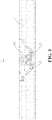
- FIG. 1 is a partial top view of an electronic assembly in an implementation of the disclosure
- FIG. 2 is a partial exploded view of an electronic assembly in an implementation of the disclosure
- FIG. 3 is a schematic cross-sectional view of FIG. 1 along direction A-A
- FIG. 4 is a schematic cross-sectional view of FIG. 1 along direction B-B.
- An electronic assembly 1 is provided in the disclosure.
- the electronic assembly 1 includes a shaft assembly 2 and housings 3 arranged oppositely.
- the shaft assembly 2 includes a first shaft case 10, first rotating members 20, and rotating units 30.
- the housings 3 are at least partially disposed at two opposite sides of the first shaft case 10.
- the first rotating members 20 are at least partially disposed at the two opposite sides of the first shaft case 10.
- Each of the first rotating members 20 has one end rotatably connected with the first shaft case 10 and the other end connected with the housings 3.
- the rotating units 30 are at least partially disposed at the two opposite sides of the first shaft case 10.
- Each of the rotating units 30 includes a second rotating member 31 and a movable plate 32.
- the second rotating member 31 has one end rotatably connected with the first shaft case 10 and the other end connected with the movable plate 32.
- the movable plate 32 has one end connected to the housings 3.
- the electronic assembly 1 provided in the disclosure mainly includes the shaft assembly 2 and the housings 3 arranged oppositely. That is, the electronic assembly 1 is a collective name of the shaft assembly 2 and the housings 3.
- the shaft assembly 2 includes the first shaft case 10.
- the first shaft case 10 can serve as a carrier for other rotating components of the shaft assembly 2, that is, the rotating components are arranged on the first shaft case 10 and can rotate around some points on the first shaft case 10.
- the first shaft case 10 can also be used to receive some other components in the shaft assembly 2, that is, some components are mounted in the first shaft case 10, which saves space.
- the first shaft case 10 can also serve as a protective case for the electronic assembly 1 and an electronic device 4, that is, the first shaft case 10 serves as part of a housing of the electronic device 4, thereby protecting components within the electronic device 4.
- FIG. 2 only illustrates the first shaft case 10 and structures at one side of the first shaft case 10, structures at the other side of the first shaft case 10 are the same as and arranged symmetrically with the structures at the one side of the first shaft case 10.
- the housings 3 of the disclosure are at least partially disposed at the two opposite sides of the first shaft case 10.
- the housings 3 and the first shaft case 10 provided in the disclosure can corporately serve as the housing of the electronic device 4.
- part of the housings 3 are disposed at the two opposite sides of the first shaft case 10, and the rest of the housings 3 are disposed at a third side of the first shaft case 10 connected with the two opposite sides, which allows the first shaft case 10 to be accommodated in a space surrounded by the housing 3, and the first shaft case 10 is protected by the housing 3 to a certain extent.
- the shaft assembly 2 provided in the disclosure further includes the first rotating members 20 at least partially disposed at the two opposite sides of the first shaft case 10.
- the first rotating member 20 can be regarded as a rotatable member.
- the first rotating member 20 is rotatably connected to a case of the shaft assembly 2, that is, the first rotating member 20 can rotate around a certain point on the first shaft case 10.
- the first rotating member 20 is fixedly connected with the housing 3 at the other end of the first rotating member 20. As such, when the first rotating member 20 rotates relative to the first shaft case 10, the first rotating member 20 can drive the housing 3 to rotate together.
- part of the first rotating members 20 is disposed at two opposite sides of the first shaft case 10, and the rest of the first rotating members 20 is disposed at the other sides of the first shaft case 10 for connecting the first shaft case 10.
- the first rotating member 20 can be rotatably connected to the first shaft case 10 directly.
- the first rotating member 20 can also be connected to the first shaft case 10 indirectly, so as to make the first rotating member 20 rotatable relative to the first shaft case 10.
- the other end of the first rotating member 20 can be fixedly connected to the housing 3.
- the other end of the first rotating member 20 can be movably connected to the housing 3 (as illustrated in FIG. 3 ).
- the shaft assembly 2 provided in the disclosure further includes the rotating units 30 at least partially disposed at the two opposite sides of the first shaft case 10.
- Each of the rotating units 30 includes the second rotating member 31 and the movable plate 32.
- the second rotating member 31 is also a rotatable member.
- the second rotating member 31 is rotatably connected with the first shaft case 10 at one end of the second rotating member 31. That is, the second rotating member 31 can rotate around a certain point on the first shaft case 10.
- the second rotating member 31 is connected with the movable plate 32 at the other end of the second rotating member 31.
- the flexible screen 5 needs to be disposed on the housings 3, meanwhile, the flexible screen 5 needs to be supported at a bottom surface thereof by a rigid structure.
- the flexible screen 5 can be supported by the movable plate 32.
- the movable plate 32 is connected with the housing 3 at one end of the movable plate 32 and is connected with the second rotating member 31 at the other end of the movable plate 32.
- the first rotating member 20 can rotate relative to the first shaft case 10 to drive the housing 3 to rotate.
- Rotation of the housings 3 can also make the movable plates 32 rotate, and the movable plates 32 can also rotate together under the action of the second rotating members 31 and eventually drive the flexible screen 5 disposed on the movable plate 32 to rotate, which can realize bending of the flexible screen 5.
- the second rotating member 31 may be directly connected with the first shaft case 10 at one end of the second rotating member 31, or the second rotating member 31 may be indirectly connected with the second shaft case 40 at the end of the second rotating member 31.
- the second rotating member 31 can be fixedly connected with the movable plate 32 at the other end of the second rotating member 31, or the second rotating member 31 can be slidably connected with the movable plate 32 at the other end of the second rotating member 31.
- the movable plate 32 can be fixedly connected with the housing 3 at one end of the movable plate 32, or the movable plate 32 can be rotatably connected with the housing 3 at the end of the movable plate 32.
- the shaft assembly 2 since the shaft assembly 2 includes two movable plates 32, the shaft assembly 2 of the disclosure can be regarded as a two-plate shaft assembly 2. Alternatively, when taking the housings 3 arranged oppositely into account, the shaft assembly 2 of the disclosure can also be regarded as a four-plate shaft assembly 2.
- the electronic assembly 1 provided in the disclosure has a simple structure, in which the first rotating members 20 is cooperated with the second rotating members 31, the first rotating member 20 is connected with the first shaft case 10 and the housing 3, the second rotating member 31 is connected with the first shaft case 10 and the movable plate 32, and the movable plate 32 is connected with the housing 3, which realizes bending of the electronic assembly 1, reduces an accumulated amount of the displacements after falling, and improves the quality of the shaft assembly 2.
- the first shaft case 10 has first sidewalls 11 arranged oppositely and second sidewalls 12 arranged oppositely. Each of the second sidewalls 12 is connected with the first sidewalls 11 arranged oppositely.
- the first rotating member 20 is rotatably connected to the first sidewall 11.
- the second rotating member 31 is rotatably connected to the second sidewall 12.
- first rotating member 20 and the second rotating member 31 can be arranged on different sidewalls respectively, which can avoid a risk of collision during rotation when the first sub-rotating member and the second rotating member 31 are arranged on the same sidewall. Moreover, arranging the first rotating member 20 and the second rotating member 31 on different sidewalls can also facilitate a subsequent crank-slider movement.
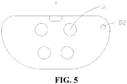
- FIG. 5 is a schematic view of a first sidewall of a first shaft case in an implementation of the disclosure.
- an orthographic projection (as illustrated by D2 in figures) of a rotation center of the second rotating member 31 on the first sidewall 11 is spaced apart from a rotation center (as illustrated by Dl in figures) of the first rotating member 20.
- the flexible screen 5 can be subsequently mounted on the movable plates 32 and the housings 3, and bending of the flexible screen 5 can realized by controlling bending of the electronic assembly 1.
- the flexible screen 5 can generally be classified into two types: "U-shaped screen” and "drop-shaped screen".
- U-shaped screen means that the flexible screen 5 is in a shape of the letter U.
- Drop-shaped screen means that the flexible screen 5 is in a shape of a water drop, that is, the flexible screen 5 has a structure that is wide at the bottom and narrow at the top.
- a "U-shaped screen” can make the overall electronic device 4 thicker, while a “drop-shaped screen” can make the overall electronic device 4 thinner.
- the orthographic projection of the rotation center of the second rotating member 31 on the first sidewall 11 can coincide with the rotation center of the first rotating member 20, that is, the first rotating member 20 and the second rotating member 31 are rotated coaxially, which allows the flexible screen 5 to be a "U-shaped screen" after installation.
- the orthographic projection of the rotation center of the second rotating member 31 on the first sidewall 11 can be spaced apart from the rotation center of the first rotating member 20, that is, the rotation center of the first rotating member 20 does not coincide with the rotation center of the second rotating member 31, and the first rotating member 20 and the second rotating member 31 do not rotate coaxially.
- a crank-slider movement is formed, so that the movable plate 32 is inclined at an angle relative to the rotating arm and the housing 3, thus a position distance is formed, and a drop-shaped screen is eventually formed.
- FIG. 6 is a schematic perspective structural view of a first shaft case and a rotating unit in another implementation of the disclosure.
- the movable plate 32 has a first sliding portion 33.
- the second rotating member 31 has a second sliding portion 34.
- the first sliding portion 33 and the second sliding portion 34 cooperate with each other to allow the movable plate 32 to slide relative to the second rotating member 31.
- the drop-shaped screen can be formed by the crank-slider movement.
- the disclosure can control and compensate the movable plate 32 or the housing 3, to increase a distance between one end of the movable plate 32 or the housing 3 away from the first shaft case 10 and the first shaft case 10, such that the electronic assembly 1 can be rotated normally, and the drop-shaped screen is eventually realized.
- it is realized by controlling and compensating the movable plate 32.
- the movable plate 32 may have the first sliding portion 33
- the second rotating member 31 may have the second sliding portion 34.
- the movable plate 32 is slidable relative to the second rotating member 31 by mutual cooperation between the first sliding portion 33 and the second sliding portion 34.
- the first sliding portion 33 may be a sliding groove or a sliding block
- the second sliding portion 34 may be a sliding block or a sliding groove. It can also be understood that when the first sliding portion 33 is a sliding groove, the second sliding portion 34 is a sliding block. When the first sliding portion 33 is a sliding block, the second sliding portion 34 is a sliding groove. In this implementation, as an example, the first sliding portion 33 is a sliding groove, and the second sliding portion 34 is a sliding block.
- FIG. 7 is a schematic perspective structural view of a movable plate and a housing in another implementation of the disclosure.
- the movable plate 32 has a first rotating portion 35 at one end thereof.
- the housing 3 has a second rotating portion 36.
- the first rotating portion 35 and the second rotating portion 36 cooperate with each other to allow the movable plate 32 to be rotatably connected with the housing 3 at one end of the movable plate 32.
- the disclosure is implemented by compensating the movable plates 32.
- the movable plate 32 will also be inclined at an angle with relative to the rotating arm and the housing 3 after the crank-slider movement, that is, the movable plate 32 will also rotate relative to the housing 3. Therefore, in this implementation, the movable plate 32 has the first rotating portion 35 at one end of the movable plate 32, and the housing 3 has the second rotating portion 36. The movable plate 32 is rotatable relative to the housing 3 through cooperation between the first rotating portion 35 and the second rotating portion 36.
- the first rotating portion 35 may be a guide rail or a sliding groove
- the second rotating portion 36 may be a sliding groove or a guide rail. It can also be understood that when the first rotating portion 35 is a guide rail, the second rotating portion 36 is a sliding groove. When the first rotating portion 35 is a sliding groove, the second rotating portion 36 is a guide rail. In this implementation, as an example, the first rotating portion 35 is a guide rail and the second rotating portion 36 is a sliding groove.
- FIG. 8 is a schematic perspective structural view of a movable plate and a housing in another implementation of the disclosure.
- the first rotating portion 35 defines a rotating hole 37.
- the second rotating portion 36 has a rotating member 38.
- the first rotating portion 35 is sleeved with the rotating member 38 through the rotating hole 37 to allow the movable plate 32 to be rotatably connected with the housing 3 at one end of the movable plate 32.
- the first rotating portion 35 defines the rotating hole 37
- the second rotating portion 36 has the rotating member 38
- the first rotating portion 35 is sleeved on the rotating member 38. In this way, the first rotating portion can rotate around the rotating member 38, so that the movable plate 32 is rotatably connected with the housing 3 at one end of the movable plate 32, and thus the movable plate 32 can rotate relative to the housing 3.
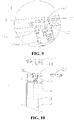
- FIG. 9 is a partial schematic perspective structural view of an electronic assembly in another implementation of the disclosure
- FIG. 10 is a partial schematic perspective structural view of a first shaft case, a second shaft case, and a first rotating member in another implementation of the disclosure.
- the electronic assembly 1 further includes second shaft cases 40 connected with the first sidewalls 11.
- the first rotating member 20 is disposed between the first sidewall 11 and the second shaft case 40.
- a second shaft case 40 can be further provided.
- the second shaft case 40 can be disposed on one side of the first sidewall 11 and connected with the first sidewall 11.
- the first rotating member 20 is disposed between the first sidewall 11 and the second shaft case 40, so as to effectively protect the first rotating member 20 and prevent the first rotating member 20 from collision with external objects.
- the second shaft case 40 and the first sidewall 11 can also cooperate with each other, so that the first rotating member 20 can be rotatably connected to the first shaft case 10 indirectly.
- the first sidewall 11 has a first positioning portion 13.
- the second shaft case 40 further has a second positioning portion 14.
- the first positioning portion 13 and the second positioning portion 14 cooperate with each other to allow the second shaft case 40 to be connected with the first sidewall 11.
- the first rotating member 20 is sleeved on the first positioning portion 13 or the second positioning portion 14.
- the first sidewall 11 can define the first positioning portion 13.
- the second shaft case 40 has the second positioning portion 14.
- the first positioning portion 13 and the second positioning portion 14 cooperate with each other to allow the second shaft case 40 to be connected with the first sidewall 11.
- the first positioning portion 13 may be a groove or a bump
- the second positioning portion 14 may be a bump or a groove. It can also be understood that when the first positioning portion 13 is a groove, the second positioning portion 14 is a bump, and when the first positioning portion 13 is a bump, the second positioning portion 14 is a groove.
- the first positioning portion 13 is a groove
- the second positioning portion 14 is a bump.
- the first rotating member 20 can also be sleeved on the first positioning portion 13 or the second positioning portion 14, that is, the first rotating member 20 can be sleeved on the bump for rotation.
- the first rotating member 20 can be sleeved on the second positioning portion 14 of the second shaft case 40, so that the first rotating member 20 can be rotatably connected with the first shaft case 10 indirectly.
- FIG. 11 is a partial schematic perspective structural view of a first shaft case and a second rotating member in another implementation of the disclosure.
- the second sidewall 12 has a third rotating portion 15.
- the second rotating member 31 has a fourth rotating portion 16.
- the third rotating portion 15 and the fourth rotating portion 16 cooperate with each other to allow the second rotating member 31 to be rotatably connected with the second sidewall 12.
- the second sidewall 12 is provided with the third rotating portion 15.
- the second rotating member 31 is provided with the fourth rotating portion 16.
- the third rotating portion 15 and the fourth rotating portion 16 cooperate with each other to allow the second rotating member 31 to be rotatably connected with the second sidewall 12.
- the third rotating portion 15 can be a rotating groove or a rotating shaft
- the fourth rotating portion 16 can be a rotating shaft or a rotating groove. It can also be understood that, when the third rotating portion 15 is a rotating groove, the fourth rotating portion 16 is a rotating shaft.
- the fourth shaft assembly 2 is the rotating groove.
- the third rotating portion 15 is the rotating groove
- the fourth rotating portion 16 is the rotating shaft. As illustrated in FIG.
- the second sidewall 12 defines the rotating grooves which opposite to each other, and the second rotating member 31 has the rotating shafts on two opposite sides of the second rotating member 31.
- the second rotating member 31 can rotate relative to the first shaft case 10 by simply inserting the rotating shaft into the rotating groove.
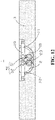
- FIG. 12 is a schematic cross-sectional view of an electronic assembly in another implementation of the disclosure.
- the first rotating members 20 at least partially disposed at the two opposite sides of the first shaft case 10 are a first rotating member (A) 21 and a first rotating member 20(B) 22.
- the electronic assembly 1 further includes a synchronization mechanism 50.
- the synchronization mechanism 50 is connected with the first rotating member (A) 21 and the first rotating member 20(B) 22 to allow the first rotating member (A) 21 and the first rotating member 20(B) 22 to synchronously rotate.
- the number of the first rotating members 20 of the disclosure is symmetrical. That is, the first rotating members 20 (i.e., the first rotating member (A) 21 and the first rotating member 20(B) 22) are arranged at a left side and a right side of the first shaft case 10.
- a synchronization mechanism 50 can be further provided.
- the synchronization mechanism 50 connects the first rotating member (A) 21 and the first rotating member 20(B) 22.
- the first rotating member 20(B) 22 can also rotate together, which makes the housings 3 and the movable plates 32 on the two opposite sides rotate together, symmetry effects when the electronic assembly 1 is rotated are improved.
- the synchronization mechanism includes a first gear 51 and a second gear 52.
- the first rotating member (A) 21 is rotatably connected with the first gear 51.
- the first gear 51 is rotatably connected with the second gear 52.
- the second gear 52 is rotatably connected with the first rotating member 20(B) 22.
- the synchronization mechanism 50 can be implemented in two ways.
- the synchronization mechanism includes a first gear 51 and a second gear 52.
- the first gear 51 is rotatably connected with the first rotating member (A) 21 and the second gear 52.
- the second gear 52 is rotatably connected with the first rotating member 20(B) 22 and the first gear 51.
- the first rotating member (A) 21 is rotated, the first rotating member 20(B) 22 can be rotated synchronously through transmission of the first gear 51 and the second gear 52.
- the first rotating member 20 has multiple hobbed teeth 23 on a peripheral side surface of the first rotating member 20.
- the multiple hobbed teeth 23 are arranged around at least one quarter of the peripheral side surface of the first rotating member 20.
- the first rotating member 20 can have multiple hobbed teeth 23 arranged on the peripheral side surface of the first rotating member 20. With aid of meshing between the hobbed teeth 23 with the first gear 51 and meshing between the hobbed teeth 23 and the second gear 52, rotational connections can be realized.
- One side of the electronic assembly 1 is usually rotated by at least 90°, and thus in the disclosure, the multiple hobbed teeth 23 are arranged around at least one quarter of the peripheral side surface of the first rotating member 20, and the number of the hobbed teeth 23 is determined according to a rotation angle, which reduces the weight of the first rotating member 20.
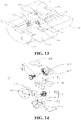
- FIG. 13 is a schematic structural view of a synchronization mechanism in another implementation of the disclosure
- FIG. 14 is an exploded view of FIG. 13
- FIG. 15 is a schematic structural view of a first bracket, a first internal gear, and a first spur gear in FIG. 13
- FIG. 16 is a schematic structural view of a second bracket, a second internal gear, and a second spur gear in FIG. 13
- FIG. 17 is a schematic diagram illustrating cooperation of the first internal gear, the second internal gear, the first spur gear, and the second spur gear in FIG. 13
- a synchronization mechanism 50 is also provided in the disclosure. In this implementation, the synchronization mechanism 50 can be received in the first shaft case 10.
- the synchronization mechanism 50 includes a first bracket 60 and a second bracket 70 connected with the first bracket 60, a first internal gear 62 and a second internal gear 72, and a first spur gear 80 and a second spur gear 83.
- the first bracket 60 and the second bracket 70 are received in the first shaft case 10.
- the first bracket 60 defines a first receiving space 61 therein.
- the second bracket 70 defines a second receiving space 71 therein.
- the first internal gear 62 is received in the first receiving space 61 and rotatable relative to the first bracket 60.
- the second internal gear 72 is received in the second receiving space 71 and rotatable relative to the second bracket 70.
- the first rotating member (A) 21 is connected with the first internal gear 62.
- the first rotating member 20(B) 22 is connected with the second internal gear 72.
- the first internal gear 62 defines a first accommodating space 63 therein.
- the second internal gear 72 defines a second accommodating space 73 therein.
- the first spur gear 80 has a first sub-spur gear 81 received in the first accommodating space 63 and a second sub-spur gear 82 disposed outside the first accommodating space 63.
- the first sub-spur gear 81 is rotatably connected with the first internal gear 62.
- the second spur gear 83 has a third sub-spur gear 84 received in the second accommodating space 73 and a fourth sub-spur gear 85 disposed outside the second accommodating space 73.
- the third sub-spur gear 84 is rotatably connected with the second internal gear 72.
- the fourth sub-spur gear 85 is rotatably connected with the second sub-spur gear 82.
- the first rotating member (A) 21 rotates
- the first internal gear 62, the second internal gear 72, the first spur gear 80, and the second spur gear 83 cooperate to allow the first rotating member (A) 21 and the first rotating member 20(B) 22 to synchronously rotate.
- the first bracket 60 is used for mounting the first internal gear 62 and the first spur gear 80
- the second bracket 70 is used for mounting the second internal gear 72 and the second spur gear 83.
- the first bracket 60 can be connected with the second bracket 70, which can reduce difficulty in forming gear pairs and reduce a size of the synchronization mechanism 50.
- the first internal gear 62 and the second internal gear 72 are further provided.
- an internal gear refers to a gear with teeth cut on an internal surface of a cylinder.
- the first internal gear 62 is disposed within the first receiving space 61 and is rotatable relative to the first bracket 60.
- the first rotating member (A) 21 is connected with the first internal gear 62. In this way, the first internal gear 62 in rotation can drive the first rotating member (A) 21 to rotate, such that the first rotating member (A) 21 is rotatably connected with the first shaft case 10 indirectly.
- the second internal gear 72 can also be received in the second receiving space 71 and rotatable relative to the second bracket 70.
- the first rotating member 20(B) 22 is connected with the second internal gear 72.
- the second internal gear 72 in rotation can drive the first rotating member 20(B) 22 to rotate, such that the first rotating member 20(B) 22 is rotatably connected with the first shaft case 10 indirectly.
- the first receiving space 61 is used for receiving the first internal gear 62.
- a rotation direction of the first internal gear 62 is consistent with an arrangement direction of teeth of the first internal gear 62.
- the second receiving space 71 is used for receiving the second internal gear 72.
- a rotation direction of the second internal gear 72 is consistent with an arrangement direction of teeth of the second internal gear 72.
- the first spur gear 80 and the second spur gear 83 are further provided.
- the first spur gear 80 includes the first sub-spur gear 81 received in the first accommodating space 63 and the second sub-spur gear 82 disposed outside the first accommodating space 63. It can also be understood that, since the teeth of the first internal gear 62 are cut on an internal surface of a cylinder, part of the first spur gear 80 needs to be received in the first accommodating space 63 and rotatably connected with the first internal gear 62, and thus a gear pair is formed. The rest of the first spur gear 80 is disposed outside the first accommodating space 63.
- the second spur gear 83 can be understood in the same way.
- the second spur gear 83 includes the third sub-spur gear 84 received in the second accommodating space 73 and the fourth sub-spur gear 85 disposed outside the second accommodating space 73. It can also be understood that, since the teeth of the second internal gear 72 are cut on an internal surface of a cylinder, part of the second spur gear 83 needs to be received in the second accommodating space 73 and rotatably connected with the second internal gear 72, and thus a gear pair is formed.
- the rest of the second spur gear 83 is disposed outside the second accommodating space 73 and is rotatably connected with the rest of the first spur gear 80 which is disposed outside the first accommodating space 63. That is, the fourth sub-spur gear 85 and the second sub-spur gear 82 are rotatably connected with each other to form a gear pair.
- the synchronization mechanism 50 by using two internal gears and two spur gears, a total of four gears cooperate with one another to form three gear pairs.
- the first internal gear 62 and the first sub-spur gear 81 cooperate with each other to form a first gear pair
- the second sub-spur gear 82 and the fourth sub-spur gear 85 cooperate with each other to form a second gear pair
- the third sub-spur gear 84 and the second internal gear 72 cooperate with each other to form a third gear pair.
- the first rotating member (A) 21 in rotation drives the first internal gear 62 to rotate, the first internal gear 62 rotates synchronously with the first sub-spur gear 81, the first sub-spur gear 81 rotates synchronously with the second sub-spur gear 82, the second sub-spur gear 82 rotates synchronously with the fourth sub-spur gear 85, the fourth sub-spur gear 85 rotates synchronously with the third sub-spur gear 84, and the third sub-spur gear 84 rotates synchronously with the second internal gear 72. Since the second internal gear 72 is connected with the first rotating member 20(B) 22, synchronous rotation of the first rotating member (A) 21 and the second rotating member 31 (B) can be eventually realized.
- the synchronization mechanism 50 provided in the disclosure has a simple structure, and can realize the synchronous rotation of the first rotating member (A) 21 and the second rotating member 31 (B) by using three gear pairs.
- the number of gear pairs is reduced, which can reduce an accumulated backlash, improve synchronization effects of the synchronization mechanism 50, and at the same time ensure structural precision of the synchronization mechanism.
- FIG. 18 is a schematic structural view of a first spur gear and a second spur gear in an implementation of the disclosure.
- the second sub-spur gear 82 has a diameter larger than the first sub-spur gear 81
- the fourth sub-spur gear 85 has a diameter larger than the third sub-spur gear 84.
- a slight distance deviation may occur between the first spur gear 80 and the second spur gear 83.
- the second sub-spur gear 82 has a diameter equal to the first sub-spur gear 81 and the fourth sub-spur gear 85 has a diameter equal to the third sub-spur gear 84, a certain gap may exist between the second sub-spur gear 82 and the fourth sub-spur gear 85, resulting in incomplete meshing.
- the second sub-spur gear 82 has a diameter larger than the first sub-spur gear 81
- the fourth sub-spur gear 85 has a diameter larger than the third sub-spur gear 84, such that the second sub-spur gear 82 and the fourth sub-spur gear 85 can fully mesh with each other no matter how much degrees the first internal gear 62 and the second internal gear 72 rotate, which improves the synchronization effects of the synchronization mechanism 50.
- the first shaft case 10 further has a baffle plate 17.
- the baffle plate 17, the first sidewall 11, and the second sidewalls 12 arranged oppositely define a third receiving space 18.
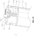
- the electronic assembly 1 further includes a damping mechanism 90 at least partially received in the third receiving space 18.
- the damping mechanism 90 includes an elastic member 94, a first limiting portion 91, and a second limiting portion 92.
- the first limiting portion 91 has one end extended through the first sidewall 11 and connected with the first gear 51 and the other end abutted against one end of the elastic member 94.
- the second limiting portion 92 has one end extended through the first sidewall 11 and connect with the second gear 52 and the other end abutted against the end of the elastic member 94.
- the elastic member 94 has the other end connected with the baffle plate 17 and the elastic member 94 is in a compressed state.
- the baffle plate 17 can be further provided, such that the baffle plate 17, the first sidewall 11, and the second sidewall 12 can cooperate with one another to define a third receiving space 18.
- the damping mechanism 90 is further received in the third receiving space 18.
- the damping mechanism 90 is used to prevent the electronic assembly 1 from being arbitrarily bent. It can also be understood that the damping mechanism 90 is used to prevent the electronic assembly 1 from being bent when a small external force is applied.
- the first limiting portion 91 is connected with the first gear 51, so that when the first gear 51 rotates, the first limiting portion 91 is driven to rotate together.
- the second limiting portion 92 can be understood in the same way.
- the elastic member 94 abuts against the first limiting portion 91 and the second limiting portion 92 at one end and is connected with the baffle plate 17 at the other end, and the elastic member 94 remains in a compressed state. That is, regardless of whether the electronic assembly 1 is in an unfolded state or a folded state, the elastic member 94 remains in a compressed state.
- the elastic member 94 applies a restoring force to the first limiting portion 91 and the second limiting portion 92, and a direction of the restoring force is perpendicular to the first sidewall 11.
- the external force can be counteracted by the restoring force, so that the electronic component 1 will not be rotated. Only when a force applied to the housing 3 is greater than a certain value, the restoring force will be counteracted, so that the electronic assembly 1 starts to rotate.
- the damping mechanism 90 further includes a third limiting portion 93.
- the third limiting portion 93 has one end connected with the elastic member 94 and the other end abutted against the first limiting portion 91 and the second limiting portion 92.
- the third limiting portion 93 can be further disposed between the elastic member 94 and the first/second limiting portion 91/92.
- the third limiting portion 93 is connected with the elastic member 94 at one end of the third limiting portion 93 and abutted against the first limiting portion 91 and the second limiting portion 92 at the other end of the third limiting portion 93.
- the restoring force is transferred to the first limiting portion 91 and the second limiting portion 92 through the third limiting portion 93, and structural stability of the damping mechanism 90 is improved by abutting the third limiting portion 93 against the first limiting portion 91 and the second limiting portion 92.
- FIG. 21 is a schematic perspective structural view of a first limiting portion and a second limiting portion in another implementation of the disclosure
- FIG. 22 is a front view of a first limiting portion and a second limiting portion in another implementation of the disclosure.
- a side surface of the first limiting portion 91 close to the third limiting portion 93 is a first flat surface 911
- a side surface of the third limiting portion 93 close to the first limiting portion 91 is a second flat surface 931.
- the first limiting portion 91 has a first protruding portion 912 protruded from part of the first flat surface 911.
- the first protruding portion 912 has a first inclined surface 913 connected with the first flat surface 911.
- the third limiting portion 93 has a second protruding portion 932 protruded from part of the second flat surface 931.
- the second protruding portion 932 has a second inclined surface 933 connected with the second flat surface 931.
- the first flat surface 911 abuts against the second flat surface 931
- the first inclined surface 913 abuts against the second inclined surface 933.
- the first limiting portion 91 abuts against the second inclined surface 933.
- the first flat surface 911 and the second flat surface 931 are parallel to first sidewall 11.
- it can also be understood that the first flat surface 911 and the second flat surface 931 are parallel to a rotation direction of the electronic assembly 1.
- the first limiting portion 91 can also has a first protruding portion 912, and the first protruding portion 912 has a first inclined surface 913.
- the third limiting portion 93 has the second protruding portion 932, and the second protruding portion 932 has a second inclined surface 933.
- the first flat surface 911 abuts against the second flat surface 931
- the first inclined surface 913 abuts against the second inclined surface 933
- the restoring force of the elastic member 94 can be transferred to the first flat surface 911 of the first limiting portion 91 through the second flat surface 931 of the third limiting portion 93, so that the electronic assembly 1 can be avoided from being rotated when subjected to a small external force.
- the housing 3 drives the first rotating member (A) 21 to rotate, the first rotating member (A) 21 drives the first gear 51 to rotate, and the first gear 51 drives the first limiting portion 91 to rotate, and then, the first flat surface 911 will be separated from the second flat surface 931, and only the first limiting portion 91 abuts against the second inclined surface 933.
- the first inclined surface 913 of the first limiting portion 91 abuts against the second inclined surface 933, or other parts of the first limiting portion 91 abut against the second inclined surface 933, as such, the restoring force transferred by the second inclined surface 933 on the first limiting portion 91 can be decomposed into components which include a rotating force, which can make the electronic assembly 1 return to the unfolded state by itself when the electronic assembly 1 is free of an external force. For example, when a user applies an external force to the electronic assembly 1 and rotates the electronic assembly 1 by 30°, the electronic assembly 1 can automatically return to the unfolded state upon removing the external force.
- the third limiting portion 93 can be moved toward the baffle plate 17, which further compresses the elastic member 94 and then improves the restoring force of the elastic member 94.
- the first protruding portion 912 further has a third flat surface 912 connected with the first inclined surface 913.
- the third flat surface 912 is parallel to the first flat surface 911.
- the second protruding portion 932 further has a fourth flat surface 934 connected with the second inclined surface 933.
- the fourth flat surface 934 is parallel to the second flat surface 931.
- the third flat surface 912 and the fourth flat surface 934 are parallel to the first sidewall 11.
- the third flat surface 912 and the fourth flat surface 934 are parallel to the rotation direction of the electronic assembly 1.
- the first protruding portion 912 further has the third flat surface 912 connected with the first inclined surface 913
- the second protruding portion 932 further has the fourth flat surface 934 connected with the second inclined surface 933.
- the electronic assembly 1 may not automatically recover to the unfolded state upon removing the external force, and secondly, the electronic assembly 1 is further prevented from being rotated under a small external force.
- the second limiting portion 92 can also have the same structure, that is, the second limiting portion 92 may also have a protruding portion on a flat surface of the second limiting portion 92, and the protruding portion also has an inclined surface and a flat surface.
- the third limiting portion 93 may also have a protruding portion, and the protruding portion also has an inclined surface and a flat surface.
- the first limiting portion 91, the second limiting portion 92, and the third limiting portion 93 may be arranged in an axis-symmetric manner, which can further improve the damping and limiting effects of the electronic assembly 1.
- an electronic device 4 is further provided in implementations of the disclosure. Both the electronic device 4 and the electronic assembly 1 provided in the disclosure can realize inventiveness of the disclosure. As an example, the electronic device 4 described hereinafter can include the electronic assembly 1 provided above.
- FIG. 23 is a partial top view of an electronic device in an unfolded state in an implementation of the disclosure
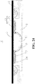
- FIG. 24 is a cross-sectional view of FIG. 23 taken along direction C-C
- FIG. 25 is a schematic perspective structural view of an electronic device in a folded state in an implementation of the disclosure
- FIG. 26 is a top view of FIG. 25
- FIG. 27 is a cross-sectional view of FIG. 26 taken along direction D-D.
- An electronic device 4 provided in this implementation includes a flexible screen 5 and the electronic assembly 1 provided in the foregoing implementations of the disclosure.
- the flexible screen 5 is mounted on the movable plate 32 of the electronic assembly 1.
- the electronic device 4 includes, but is not limited to, a cell phone, a tablet, a laptop, a personal computer (PC), a personal digital assistants (PDA), a portable media player (PMP), a navigation device, a wearable device, a smart bracelet, a pedometer, and other mobile terminals, as well as a fixed terminal such as a digital television (TV) and a desktop computer.
- a cell phone a tablet, a laptop, a personal computer (PC), a personal digital assistants (PDA), a portable media player (PMP), a navigation device, a wearable device, a smart bracelet, a pedometer, and other mobile terminals, as well as a fixed terminal such as a digital television (TV) and a desktop computer.
- PC personal computer
- PDA personal digital assistants
- PMP portable media player
- TV digital television
- TV digital television
- the flexible screen 5 can be mounted on the movable plates 32 to allow the flexible screen 5 to be bent inwardly, that is, when the electronic device 4 is bent, the flexible screen 5 is not exposed, instead, the flexible screen 5 is protected by the housings 3. It is clear from the above that when the housings 3 are bent under an external force, the housings 3 can drive the movable plates 32 to bend together, and the movable plates 32 in turn drive the flexible screen 5 on the movable plates 32 to bend.
- the electronic device 4 can be bent, and the drop-shaped screen is also achieved, which reduces an accumulated amount of the displacements after falling, improves the quality of the electronic device 4, and ensures precision of the electronic device 4.
- the first shaft case 10 defines an avoidance groove 95 on one side of the first shaft case 10 close to the flexible screen 5.
- the avoidance groove 95 is configured to receive part of the flexible screen 5 when the electronic device 4 is bent.
- the flexible screen 5 will have a certain displacement in a direction towards the first shaft case 10 at a position where the flexible screen 5 is bent.
- the first shaft case 10 can define the avoidance groove 95 on one side of the first shaft case 10 close to the flexible screen 5, so that when the flexible screen 5 is bent, the avoidance groove 95 may accommodate part of the flexible screen 5 that is displaced in the direction towards the first shaft case 10, which can prevent the flexible screen 5 during bending from collision with the first shaft case 10 and protect the flexible screen 5.
Landscapes
- Engineering & Computer Science (AREA)
- Theoretical Computer Science (AREA)
- Computer Hardware Design (AREA)
- General Engineering & Computer Science (AREA)
- Physics & Mathematics (AREA)
- General Physics & Mathematics (AREA)
- Human Computer Interaction (AREA)
- Signal Processing (AREA)
- Mechanical Engineering (AREA)
- Microelectronics & Electronic Packaging (AREA)
- Telephone Set Structure (AREA)
- Casings For Electric Apparatus (AREA)
- Pivots And Pivotal Connections (AREA)
Abstract
Description
- This application relates to the technical field of electronic products, and in particular, to an electronic assembly and an electronic device.
- With the continuous development of electronic products, the electronic product is now favored by users due to its portability and a variety of operability. However, at the same time, the users' expectations and requirements for the electronic products are also getting higher and higher. For example, in flexible electronic devices, a shaft assembly is one of important structural components to control rotation of the electronic device. However, a current shaft assembly is relatively complex in structure, which increases total gaps, thus displacements after falling are enlarged, and a quality of the shaft assembly is declined.
- In view of above, in a first aspect of the disclosure, an electronic assembly is provided. The electronic assembly includes a shaft assembly and housings arranged oppositely. The shaft assembly includes a first shaft case, first rotating members, and rotating units. The housings are at least partially disposed at two opposite sides of the first shaft case. The first rotating members are at least partially disposed at the two opposite sides of the first shaft case. Each of the first rotating members has one end rotatably connected with the first shaft case and the other end connected with the housings. The rotating units are at least partially disposed at the two opposite sides of the first shaft case. Each of the rotating units includes a second rotating member and a movable plate. The second rotating member has one end rotatably connected with the first shaft case and the other end connected with the movable plate. The movable plate has one end connected to the housings.
- In a second aspect of the disclosure, an electronic device is provided. The electronic device includes a flexible screen and the electronic assembly provided in the first aspect of the disclosure. The flexible screen is mounted on the movable plate of the electronic assembly.
- In order to describe technical solutions in implementations of the disclosure more clearly, the following will give a brief introduction to the accompanying drawings used for describing the implementations.
-
FIG. 1 is a partial top view of an electronic assembly in an implementation of the disclosure. -
FIG. 2 is a partial exploded view of an electronic assembly in an implementation of the disclosure. -
FIG. 3 is a schematic cross-sectional view ofFIG. 1 along direction A-A. -
FIG. 4 is a schematic cross-sectional view ofFIG. 1 along direction B-B. -
FIG. 5 is a schematic view of a first sidewall of a first shaft case in an implementation of the disclosure. -
FIG. 6 is a schematic perspective structural view of a first shaft case and a rotating unit in another implementation of the disclosure. -
FIG. 7 is a schematic perspective structural view of a movable plate and a housing in another implementation of the disclosure. -
FIG. 8 is a schematic perspective structural view of a movable plate and a housing in another implementation of the disclosure. -
FIG. 9 is a partial schematic perspective structural view of an electronic assembly in another implementation of the disclosure. -
FIG. 10 is a partial schematic perspective structural view of a first shaft case, a second shaft case, and a first rotating member in another implementation of the disclosure. -
FIG. 11 is a partial schematic perspective structural view of a first shaft case and a second rotating member in another implementation of the disclosure. -
FIG. 12 is a schematic cross-sectional view of an electronic assembly in another implementation of the disclosure. -
FIG. 13 is a schematic structural view of a synchronization mechanism in another implementation of the disclosure. -
FIG. 14 is an exploded view ofFIG. 13 . -
FIG. 15 is a schematic structural view of a first bracket, a first internal gear, and a first spur gear inFIG. 13 . -
FIG. 16 is a schematic structural view of a second bracket, a second internal gear, and a second spur gear inFIG. 13 . -
FIG. 17 is a schematic diagram illustrating cooperation of the first internal gear, the second internal gear, the first spur gear, and the second spur gear inFIG. 13 . -
FIG. 18 is a schematic structural view of a first spur gear and a second spur gear in an implementation of the disclosure. -
FIG. 19 is a partial schematic perspective structural view of an electronic assembly in another implementation of the disclosure. -
FIG. 20 is a partial schematic perspective structural view of an electronic assembly in another implementation of the disclosure. -
FIG. 21 is a schematic perspective structural view of a first limiting portion and a second limiting portion in another implementation of the disclosure. -
FIG. 22 is a front view of a first limiting portion and a second limiting portion in another implementation of the disclosure. -
FIG. 23 is a partial top view of an electronic device in an unfolded state in an implementation of the disclosure. -
FIG. 24 is a cross-sectional view ofFIG. 23 taken along direction C-C. -
FIG. 25 is a schematic perspective structural view of an electronic device in a folded state in an implementation of the disclosure. -
FIG. 26 is a top view ofFIG. 25 . -
FIG. 27 is a cross-sectional view ofFIG. 26 taken along direction D-D. - electronic assembly - 1, shaft assembly - 2, housing - 3, electronic device - 4, flexible screen - 5, first shaft case - 10, first sidewall - 11, second sidewall - 12, first positioning portion - 13, second positioning portion - 14, third rotating portion - 15, fourth rotating portion - 16, baffle plate - 17, third receiving space - 18, first rotating member - 20, first rotating member (A) - 21, first rotating member (B) - 22, hobbed teeth - 23, rotating unit - 30, second rotating member - 31, movable plate - 32, first sliding portion - 33, second sliding portion - 34, first rotating portion - 35, second rotating portion - 36, rotating hole - 37, rotating member - 38, second shaft case - 40, synchronization mechanism - 50, first gear - 51, second gear - 52, first bracket - 60, first receiving space - 61, first internal gear - 62, first accommodating space - 63, second bracket - 70, second receiving space - 71, second internal gear - 72, second accommodating space - 73, first spur gear - 80, first sub-spur gear - 81, second sub-spur gear - 82, second spur gear - 83, third sub-spur gear - 84, fourth sub-spur gear - 85, damping mechanism - 90, first limiting portion - 91, first flat surface - 911, first protruding portion - 912, first inclined surface - 913, third flat surface - 914, second limiting portion - 92, third limiting portion - 93, second flat surface - 931, second protruding portion - 932, second inclined surface - 933, fourth flat surface - 934, elastic member - 94, avoidance groove - 95.
- The below description are preferred implementations of the disclosure, and it is noted that various improvements and modifications can be made without departing from the principle of the application to those of ordinary skill in the art, and the improvement and the modification are also considered as the protection scope of the disclosure.
- An electronic assembly is provided in the disclosure. The electronic assembly includes a shaft assembly and housings arranged oppositely. The shaft assembly includes a first shaft case, first rotating members, and rotating units. The housings are at least partially disposed at two opposite sides of the first shaft case. The first rotating members are at least partially disposed at the two opposite sides of the first shaft case. Each of the first rotating members has one end rotatably connected with the first shaft case and the other end connected with the housings. The rotating units are at least partially disposed at the two opposite sides of the first shaft case. Each of the rotating units includes a second rotating member and a movable plate. The second rotating member has one end rotatably connected with the first shaft case and the other end connected with the movable plate. The movable plate has one end connected to the housings.
- In an implementation, the first shaft case has first sidewalls arranged oppositely and second sidewalls arranged oppositely. Each of the second sidewalls is connected with the first sidewalls arranged oppositely. The first rotating member is rotatably connected to the first sidewall. The second rotating member is rotatably connected to the second sidewall.
- In an implementation, an orthographic projection of a rotation center of the second rotating member on the first sidewall is spaced apart from a rotation center of the first rotating member.
- In an implementation, the movable plate has a first sliding portion. The second rotating member has a second sliding portion. The first sliding portion and the second sliding portion cooperate with each other to allow the movable plate to slide relative to the second rotating member.
- In an implementation, the movable plate has a first rotating portion at one end thereof. The housing has a second rotating portion. The first rotating portion and the second rotating portion cooperate with each other to allow the movable plate to be rotatably connected with the housing at one end of the movable plate.
- In an implementation, the first rotating portion defines a rotating hole. The second rotating portion has a rotating member. The first rotating portion is sleeved with the rotating member through the rotating hole to allow the movable plate to be rotatably connected with the housing at one end of the movable plate.
- In an implementation, the electronic assembly further includes second shaft cases connected with the first sidewalls. The first rotating member is disposed between the first sidewall and the second shaft case.
- In an implementation, the first sidewall has a first positioning portion. The second shaft case further has a second positioning portion. The first positioning portion and the second positioning portion cooperate with each other to allow the second shaft case to be connected with the first sidewall. The first rotating member is sleeved on the first positioning portion or the second positioning portion.
- In an implementation, the second sidewall has a third rotating portion. The second rotating member has a fourth rotating portion. The third rotating portion and the fourth rotating portion cooperate with each other to allow the second rotating member to be rotatably connected with the second sidewall.
- In an implementation, the electronic assembly further includes a synchronization mechanism. The first rotating members are at least partially disposed at the two opposite sides of the first shaft case are a first rotating member (A) and a first rotating member (B). The synchronization mechanism is connected with the first rotating member (A) and the first rotating member (B) to allow the first rotating member (A) and the first rotating member (B) to synchronously rotate.
- In an implementation, the synchronization mechanism includes a first gear and a second gear, the first rotating member (A) is rotatably connected with the first gear. The first gear is rotatably connected with the second gear. The second gear is rotatably connected with the first rotating member (B).
- In an implementation, the first rotating member has multiple hobbed teeth on a peripheral side surface of the first rotating member. The multiple hobbed teeth are arranged around at least one quarter of the peripheral side surface of the first rotating member.
- In an implementation, the synchronization mechanism includes a first bracket and a second bracket connected with the first bracket, a first internal gear and a second internal gear, and a first spur gear and a second spur gear. The first bracket and the second bracket are received in the first shaft case. The first bracket defines a first receiving space therein. The second bracket defines a second receiving space therein. The first internal gear is received in the first receiving space and rotatable relative to the first bracket. The second internal gear is received in the second receiving space and rotatable relative to the second bracket. The first rotating member (A) is connected with the first internal gear. The first rotating member (B) is connected with the second internal gear. The first internal gear defines a first accommodating space therein. The second internal gear defines a second accommodating space therein. The first spur gear has a first sub-spur gear received in the first accommodating space and a second sub-spur gear disposed outside the first accommodating space. The first sub-spur gear is rotatably connected with the first internal gear. The second spur gear has a third sub-spur gear received in the second accommodating space and a fourth sub-spur gear disposed outside the second accommodating space. The third sub-spur gear is rotatably connected with the second internal gear. The fourth sub-spur gear is rotatably connected with the second sub-spur gear. When the first rotating member (A) rotates, the first internal gear, the second internal gear, the first spur gear, and the second spur gear cooperate to allow the first rotating member (A) and the first rotating member (B) to synchronously rotate.
- In an implementation, the second sub-spur gear has a diameter larger than the first sub-spur gear, the fourth sub-spur gear has a diameter larger than the third sub-spur gear.
- In an implementation, the first shaft case further has a baffle plate. The baffle plate, the first sidewall, and the second sidewalls arranged oppositely define a third receiving space. The electronic assembly further includes a damping mechanism at least partially received in the third receiving space. The damping mechanism includes an elastic member, a first limiting portion, and a second limiting portion. The first limiting portion has one end extended through the first sidewall and connected with the first gear and the other end abutted against one end of the elastic member. The second limiting portion has one end extended through the first sidewall and connect with the second gear and the other end abutted against the end of the elastic member. The elastic member has the other end connected with the baffle plate and the elastic member is in a compressed state.
- In an implementation, the damping mechanism further includes a third limiting portion. The third limiting portion has one end connected with the elastic member and the other end abutted against the first limiting portion and the second limiting portion.
- In an implementation, a side surface of the first limiting portion close to the third limiting portion is a first flat surface. A side surface of the third limiting portion close to the first limiting portion is a second flat surface. The first limiting portion has a first protruding portion protruded from part of the first flat surface. The first protruding portion has a first inclined surface connected with the first flat surface. The third limiting portion has a second protruding portion protruded from part of the second flat surface. The second protruding portion has a second inclined surface connected with the second flat surface. When the electronic assembly is in unfolded state, the first flat surface abuts against the second flat surface, and the first inclined surface abuts against the second inclined surface. When the electronic assembly rotates, the first limiting portion abuts against the second inclined surface.
- In an implementation, the first protruding portion further has a third flat surface connected with the first inclined surface. The third flat surface is parallel to the first flat surface. The second protruding portion further has a fourth flat surface connected with the second inclined surface. The fourth flat surface is parallel to the second flat surface. When the electronic assembly is folded to a predetermined angle, the second flat surface abuts against the fourth flat surface.
- An electronic device is further provided in the implementations of the disclosure. The electronic device includes a flexible screen and the electronic assembly provided in the foregoing implementations of the disclosure. The flexible screen is mounted on the movable plate of the electronic assembly.
- In an implementation, the first shaft case defines an avoidance groove on one side of the first shaft case close to the flexible screen. The avoidance groove is configured to receive part of the flexible screen when the electronic device is bent.
- Before describing technical solutions of the disclosure, technical problems in the related art are introduced below in detail.
- In flexible electronic devices, the shaft assembly is one of important structural components to control rotation of the flexible electronic device. There are many kinds of shaft assemblies, usually named by the number of plates which are in the shaft assembly and for supporting a flexible screen, such as a two-plate shaft assembly, a four-plate shaft assembly, and a five-plate shaft assembly. In a case that the shaft assembly has a larger number of plates (for example, five plates), a gap will exist between two adjacent plates, and thus the five-plate shaft assembly will have one more gap and one more step (also known as a mismatch gap) than the four-plate shaft assembly, which will adversely affect surface effect of the flexible screen. This happens because, firstly, there will be no rigid support for the flexible screen at a position opposite to the gap, and secondly, the gap will also affect flushness between two adjacent panels, which results in a height difference of the flexible screen at different positions, and eventually adversely affects the surface effect of the flexible screen. The four-plate shaft assembly in the related art has a complex structure and a larger number of components, and there is an assembly tolerance between each two components, which may increase total gaps, increase the size of a dimensional chain, enlarge displacements after falling, and decline a quality of the shaft assembly.
- In view of above, an electronic assembly is provided in the disclosure, and a first rotating member and a second rotating member cooperate with each other to allow the electronic assembly to rotate, which simplifies a shaft assembly in structure and improves a quality of the shaft assembly.
- Referring to
FIGS. 1-4 ,FIG. 1 is a partial top view of an electronic assembly in an implementation of the disclosure,FIG. 2 is a partial exploded view of an electronic assembly in an implementation of the disclosure,FIG. 3 is a schematic cross-sectional view ofFIG. 1 along direction A-A, andFIG. 4 is a schematic cross-sectional view ofFIG. 1 along direction B-B. Anelectronic assembly 1 is provided in the disclosure. Theelectronic assembly 1 includes ashaft assembly 2 andhousings 3 arranged oppositely. Theshaft assembly 2 includes afirst shaft case 10, first rotatingmembers 20, androtating units 30. Thehousings 3 are at least partially disposed at two opposite sides of thefirst shaft case 10. The firstrotating members 20 are at least partially disposed at the two opposite sides of thefirst shaft case 10. Each of the firstrotating members 20 has one end rotatably connected with thefirst shaft case 10 and the other end connected with thehousings 3. The rotatingunits 30 are at least partially disposed at the two opposite sides of thefirst shaft case 10. Each of therotating units 30 includes a second rotatingmember 31 and amovable plate 32. The second rotatingmember 31 has one end rotatably connected with thefirst shaft case 10 and the other end connected with themovable plate 32. Themovable plate 32 has one end connected to thehousings 3. - The
electronic assembly 1 provided in the disclosure mainly includes theshaft assembly 2 and thehousings 3 arranged oppositely. That is, theelectronic assembly 1 is a collective name of theshaft assembly 2 and thehousings 3. In an implementation, theshaft assembly 2 includes thefirst shaft case 10. Firstly, thefirst shaft case 10 can serve as a carrier for other rotating components of theshaft assembly 2, that is, the rotating components are arranged on thefirst shaft case 10 and can rotate around some points on thefirst shaft case 10. Secondly, thefirst shaft case 10 can also be used to receive some other components in theshaft assembly 2, that is, some components are mounted in thefirst shaft case 10, which saves space. Furthermore, thefirst shaft case 10 can also serve as a protective case for theelectronic assembly 1 and anelectronic device 4, that is, thefirst shaft case 10 serves as part of a housing of theelectronic device 4, thereby protecting components within theelectronic device 4.FIG. 2 only illustrates thefirst shaft case 10 and structures at one side of thefirst shaft case 10, structures at the other side of thefirst shaft case 10 are the same as and arranged symmetrically with the structures at the one side of thefirst shaft case 10. - Additionally, the
housings 3 of the disclosure are at least partially disposed at the two opposite sides of thefirst shaft case 10. Thehousings 3 and thefirst shaft case 10 provided in the disclosure can corporately serve as the housing of theelectronic device 4. In this implementation, as illustrated inFIG. 1 , part of thehousings 3 are disposed at the two opposite sides of thefirst shaft case 10, and the rest of thehousings 3 are disposed at a third side of thefirst shaft case 10 connected with the two opposite sides, which allows thefirst shaft case 10 to be accommodated in a space surrounded by thehousing 3, and thefirst shaft case 10 is protected by thehousing 3 to a certain extent. - As illustrated in
FIG. 3 , theshaft assembly 2 provided in the disclosure further includes the firstrotating members 20 at least partially disposed at the two opposite sides of thefirst shaft case 10. The first rotatingmember 20 can be regarded as a rotatable member. In an implementation, the first rotatingmember 20 is rotatably connected to a case of theshaft assembly 2, that is, the first rotatingmember 20 can rotate around a certain point on thefirst shaft case 10. The first rotatingmember 20 is fixedly connected with thehousing 3 at the other end of the first rotatingmember 20. As such, when the first rotatingmember 20 rotates relative to thefirst shaft case 10, the first rotatingmember 20 can drive thehousing 3 to rotate together. In this implementation, as an example, part of the firstrotating members 20 is disposed at two opposite sides of thefirst shaft case 10, and the rest of the firstrotating members 20 is disposed at the other sides of thefirst shaft case 10 for connecting thefirst shaft case 10. In an implementation, the first rotatingmember 20 can be rotatably connected to thefirst shaft case 10 directly. Alternatively, the first rotatingmember 20 can also be connected to thefirst shaft case 10 indirectly, so as to make the first rotatingmember 20 rotatable relative to thefirst shaft case 10. In an implementation, the other end of the first rotatingmember 20 can be fixedly connected to thehousing 3. Alternatively, the other end of the first rotatingmember 20 can be movably connected to the housing 3 (as illustrated inFIG. 3 ). - As illustrated in
FIG. 4 , theshaft assembly 2 provided in the disclosure further includes therotating units 30 at least partially disposed at the two opposite sides of thefirst shaft case 10. Each of therotating units 30 includes the second rotatingmember 31 and themovable plate 32. The second rotatingmember 31 is also a rotatable member. The second rotatingmember 31 is rotatably connected with thefirst shaft case 10 at one end of the second rotatingmember 31. That is, the second rotatingmember 31 can rotate around a certain point on thefirst shaft case 10. The second rotatingmember 31 is connected with themovable plate 32 at the other end of the second rotatingmember 31. In theelectronic device 4, theflexible screen 5 needs to be disposed on thehousings 3, meanwhile, theflexible screen 5 needs to be supported at a bottom surface thereof by a rigid structure. Thus, in the disclosure, theflexible screen 5 can be supported by themovable plate 32. - In addition, the
movable plate 32 is connected with thehousing 3 at one end of themovable plate 32 and is connected with the second rotatingmember 31 at the other end of themovable plate 32. In an implementation, when thehousing 3 is subjected to a rotary force, the first rotatingmember 20 can rotate relative to thefirst shaft case 10 to drive thehousing 3 to rotate. Rotation of thehousings 3 can also make themovable plates 32 rotate, and themovable plates 32 can also rotate together under the action of the secondrotating members 31 and eventually drive theflexible screen 5 disposed on themovable plate 32 to rotate, which can realize bending of theflexible screen 5. In an implementation, the second rotatingmember 31 may be directly connected with thefirst shaft case 10 at one end of the second rotatingmember 31, or the second rotatingmember 31 may be indirectly connected with thesecond shaft case 40 at the end of the second rotatingmember 31. In an implementation, the second rotatingmember 31 can be fixedly connected with themovable plate 32 at the other end of the second rotatingmember 31, or the second rotatingmember 31 can be slidably connected with themovable plate 32 at the other end of the second rotatingmember 31. In an implementation, themovable plate 32 can be fixedly connected with thehousing 3 at one end of themovable plate 32, or themovable plate 32 can be rotatably connected with thehousing 3 at the end of themovable plate 32. In an implementation, since theshaft assembly 2 includes twomovable plates 32, theshaft assembly 2 of the disclosure can be regarded as a two-plate shaft assembly 2. Alternatively, when taking thehousings 3 arranged oppositely into account, theshaft assembly 2 of the disclosure can also be regarded as a four-plate shaft assembly 2. - To sum up, the
electronic assembly 1 provided in the disclosure has a simple structure, in which the firstrotating members 20 is cooperated with the secondrotating members 31, the first rotatingmember 20 is connected with thefirst shaft case 10 and thehousing 3, the second rotatingmember 31 is connected with thefirst shaft case 10 and themovable plate 32, and themovable plate 32 is connected with thehousing 3, which realizes bending of theelectronic assembly 1, reduces an accumulated amount of the displacements after falling, and improves the quality of theshaft assembly 2. - In an implementation, referring to
FIG. 2 , in this implementation, thefirst shaft case 10 has first sidewalls 11 arranged oppositely andsecond sidewalls 12 arranged oppositely. Each of thesecond sidewalls 12 is connected with thefirst sidewalls 11 arranged oppositely. The first rotatingmember 20 is rotatably connected to thefirst sidewall 11. The second rotatingmember 31 is rotatably connected to thesecond sidewall 12. - In this implementation, the first rotating
member 20 and the second rotatingmember 31 can be arranged on different sidewalls respectively, which can avoid a risk of collision during rotation when the first sub-rotating member and the second rotatingmember 31 are arranged on the same sidewall. Moreover, arranging the first rotatingmember 20 and the second rotatingmember 31 on different sidewalls can also facilitate a subsequent crank-slider movement. - Referring to
FIGS. 2-5 ,FIG. 5 is a schematic view of a first sidewall of a first shaft case in an implementation of the disclosure. In this implementation, an orthographic projection (as illustrated by D2 in figures) of a rotation center of the second rotatingmember 31 on thefirst sidewall 11 is spaced apart from a rotation center (as illustrated by Dl in figures) of the first rotatingmember 20. - In the
electronic assembly 1 provided in the disclosure, theflexible screen 5 can be subsequently mounted on themovable plates 32 and thehousings 3, and bending of theflexible screen 5 can realized by controlling bending of theelectronic assembly 1. According to a shape of theflexible screen 5 after being bent, theflexible screen 5 can generally be classified into two types: "U-shaped screen" and "drop-shaped screen". "U-shaped screen" means that theflexible screen 5 is in a shape of the letter U. "Drop-shaped screen" means that theflexible screen 5 is in a shape of a water drop, that is, theflexible screen 5 has a structure that is wide at the bottom and narrow at the top. A "U-shaped screen" can make the overallelectronic device 4 thicker, while a "drop-shaped screen" can make the overallelectronic device 4 thinner. In an implementation, the orthographic projection of the rotation center of the second rotatingmember 31 on thefirst sidewall 11 can coincide with the rotation center of the first rotatingmember 20, that is, the first rotatingmember 20 and the second rotatingmember 31 are rotated coaxially, which allows theflexible screen 5 to be a "U-shaped screen" after installation. In this implementation, the orthographic projection of the rotation center of the second rotatingmember 31 on thefirst sidewall 11 can be spaced apart from the rotation center of the first rotatingmember 20, that is, the rotation center of the first rotatingmember 20 does not coincide with the rotation center of the second rotatingmember 31, and the first rotatingmember 20 and the second rotatingmember 31 do not rotate coaxially. In this way, when the first rotatingmember 20 and the second rotatingmember 31 are rotated, a crank-slider movement is formed, so that themovable plate 32 is inclined at an angle relative to the rotating arm and thehousing 3, thus a position distance is formed, and a drop-shaped screen is eventually formed. - Referring to
FIG. 4 andFIG. 6 together,FIG. 6 is a schematic perspective structural view of a first shaft case and a rotating unit in another implementation of the disclosure. In this implementation, themovable plate 32 has a first slidingportion 33. The second rotatingmember 31 has a second slidingportion 34. The first slidingportion 33 and the second slidingportion 34 cooperate with each other to allow themovable plate 32 to slide relative to the second rotatingmember 31. - As can be seen from above, the drop-shaped screen can be formed by the crank-slider movement. In order to realize the crank-slider movement, the disclosure can control and compensate the
movable plate 32 or thehousing 3, to increase a distance between one end of themovable plate 32 or thehousing 3 away from thefirst shaft case 10 and thefirst shaft case 10, such that theelectronic assembly 1 can be rotated normally, and the drop-shaped screen is eventually realized. In this implementation, it is realized by controlling and compensating themovable plate 32. In an implementation, themovable plate 32 may have the first slidingportion 33, and the second rotatingmember 31 may have the second slidingportion 34. Themovable plate 32 is slidable relative to the second rotatingmember 31 by mutual cooperation between the first slidingportion 33 and the second slidingportion 34. In an implementation, the first slidingportion 33 may be a sliding groove or a sliding block, and the second slidingportion 34 may be a sliding block or a sliding groove. It can also be understood that when the first slidingportion 33 is a sliding groove, the second slidingportion 34 is a sliding block. When the first slidingportion 33 is a sliding block, the second slidingportion 34 is a sliding groove. In this implementation, as an example, the first slidingportion 33 is a sliding groove, and the second slidingportion 34 is a sliding block. - Referring to
FIGS. 4-7 ,FIG. 7 is a schematic perspective structural view of a movable plate and a housing in another implementation of the disclosure. In this implementation, themovable plate 32 has a first rotatingportion 35 at one end thereof. Thehousing 3 has a secondrotating portion 36. The firstrotating portion 35 and the second rotatingportion 36 cooperate with each other to allow themovable plate 32 to be rotatably connected with thehousing 3 at one end of themovable plate 32. - As can be seen from above, when the crank-slider movement is performed, both the
movable plates 32 and thehousings 3 will rotate, and the disclosure is implemented by compensating themovable plates 32. In order to achieve the drop-shaped screen, in the disclosure, themovable plate 32 will also be inclined at an angle with relative to the rotating arm and thehousing 3 after the crank-slider movement, that is, themovable plate 32 will also rotate relative to thehousing 3. Therefore, in this implementation, themovable plate 32 has the first rotatingportion 35 at one end of themovable plate 32, and thehousing 3 has the second rotatingportion 36. Themovable plate 32 is rotatable relative to thehousing 3 through cooperation between the first rotatingportion 35 and the second rotatingportion 36. In an implementation, the first rotatingportion 35 may be a guide rail or a sliding groove, and the second rotatingportion 36 may be a sliding groove or a guide rail. It can also be understood that when the first rotatingportion 35 is a guide rail, the second rotatingportion 36 is a sliding groove. When the first rotatingportion 35 is a sliding groove, the second rotatingportion 36 is a guide rail. In this implementation, as an example, the first rotatingportion 35 is a guide rail and the second rotatingportion 36 is a sliding groove. - Referring to
FIG. 8 , which is a schematic perspective structural view of a movable plate and a housing in another implementation of the disclosure. In this implementation, the first rotatingportion 35 defines arotating hole 37. The secondrotating portion 36 has a rotatingmember 38. The firstrotating portion 35 is sleeved with the rotatingmember 38 through the rotatinghole 37 to allow themovable plate 32 to be rotatably connected with thehousing 3 at one end of themovable plate 32. In another implementation provided in the disclosure, the first rotatingportion 35 defines therotating hole 37, the second rotatingportion 36 has the rotatingmember 38, and the first rotatingportion 35 is sleeved on the rotatingmember 38. In this way, the first rotating portion can rotate around the rotatingmember 38, so that themovable plate 32 is rotatably connected with thehousing 3 at one end of themovable plate 32, and thus themovable plate 32 can rotate relative to thehousing 3. - Referring to
FIG. 9 and FIG. 10, FIG. 9 is a partial schematic perspective structural view of an electronic assembly in another implementation of the disclosure, andFIG. 10 is a partial schematic perspective structural view of a first shaft case, a second shaft case, and a first rotating member in another implementation of the disclosure. In this implementation, theelectronic assembly 1 further includessecond shaft cases 40 connected with thefirst sidewalls 11. The first rotatingmember 20 is disposed between thefirst sidewall 11 and thesecond shaft case 40. - In the disclosure, a
second shaft case 40 can be further provided. Thesecond shaft case 40 can be disposed on one side of thefirst sidewall 11 and connected with thefirst sidewall 11. The first rotatingmember 20 is disposed between thefirst sidewall 11 and thesecond shaft case 40, so as to effectively protect the first rotatingmember 20 and prevent the first rotatingmember 20 from collision with external objects. Secondly, thesecond shaft case 40 and thefirst sidewall 11 can also cooperate with each other, so that the first rotatingmember 20 can be rotatably connected to thefirst shaft case 10 indirectly. Referring toFIG. 10 , in this implementation, thefirst sidewall 11 has afirst positioning portion 13. Thesecond shaft case 40 further has asecond positioning portion 14. Thefirst positioning portion 13 and thesecond positioning portion 14 cooperate with each other to allow thesecond shaft case 40 to be connected with thefirst sidewall 11. The first rotatingmember 20 is sleeved on thefirst positioning portion 13 or thesecond positioning portion 14. - In the disclosure, the
first sidewall 11 can define thefirst positioning portion 13. Thesecond shaft case 40 has thesecond positioning portion 14. Thefirst positioning portion 13 and thesecond positioning portion 14 cooperate with each other to allow thesecond shaft case 40 to be connected with thefirst sidewall 11. In an implementation, thefirst positioning portion 13 may be a groove or a bump, and thesecond positioning portion 14 may be a bump or a groove. It can also be understood that when thefirst positioning portion 13 is a groove, thesecond positioning portion 14 is a bump, and when thefirst positioning portion 13 is a bump, thesecond positioning portion 14 is a groove. In this implementation, thefirst positioning portion 13 is a groove, and thesecond positioning portion 14 is a bump. Secondly, the first rotatingmember 20 can also be sleeved on thefirst positioning portion 13 or thesecond positioning portion 14, that is, the first rotatingmember 20 can be sleeved on the bump for rotation. For example, in this implementation, the first rotatingmember 20 can be sleeved on thesecond positioning portion 14 of thesecond shaft case 40, so that the first rotatingmember 20 can be rotatably connected with thefirst shaft case 10 indirectly. - Referring to
FIG. 11 , which is a partial schematic perspective structural view of a first shaft case and a second rotating member in another implementation of the disclosure. In this implementation, thesecond sidewall 12 has a thirdrotating portion 15. The second rotatingmember 31 has a fourth rotatingportion 16. The thirdrotating portion 15 and the fourth rotatingportion 16 cooperate with each other to allow the second rotatingmember 31 to be rotatably connected with thesecond sidewall 12. - In the disclosure, the
second sidewall 12 is provided with the third rotatingportion 15. The second rotatingmember 31 is provided with the fourth rotatingportion 16. The thirdrotating portion 15 and the fourth rotatingportion 16 cooperate with each other to allow the second rotatingmember 31 to be rotatably connected with thesecond sidewall 12. In an implementation, the third rotatingportion 15 can be a rotating groove or a rotating shaft, and the fourth rotatingportion 16 can be a rotating shaft or a rotating groove. It can also be understood that, when the third rotatingportion 15 is a rotating groove, the fourth rotatingportion 16 is a rotating shaft. When the third rotatingportion 15 is the rotating shaft, thefourth shaft assembly 2 is the rotating groove. In this implementation, as an example, the third rotatingportion 15 is the rotating groove, and the fourth rotatingportion 16 is the rotating shaft. As illustrated inFIG. 14 , thesecond sidewall 12 defines the rotating grooves which opposite to each other, and the second rotatingmember 31 has the rotating shafts on two opposite sides of the second rotatingmember 31. The second rotatingmember 31 can rotate relative to thefirst shaft case 10 by simply inserting the rotating shaft into the rotating groove. - Referring to
FIG. 12 , which is a schematic cross-sectional view of an electronic assembly in another implementation of the disclosure. In this implementation, the firstrotating members 20 at least partially disposed at the two opposite sides of thefirst shaft case 10 are a first rotating member (A) 21 and a first rotating member 20(B) 22. Theelectronic assembly 1 further includes asynchronization mechanism 50. Thesynchronization mechanism 50 is connected with the first rotating member (A) 21 and the first rotating member 20(B) 22 to allow the first rotating member (A) 21 and the first rotating member 20(B) 22 to synchronously rotate. - The number of the first
rotating members 20 of the disclosure is symmetrical. That is, the first rotating members 20 (i.e., the first rotating member (A) 21 and the first rotating member 20(B) 22) are arranged at a left side and a right side of thefirst shaft case 10. In this disclosure, asynchronization mechanism 50 can be further provided. Thesynchronization mechanism 50 connects the first rotating member (A) 21 and the first rotating member 20(B) 22. As such, when the first rotating member (A) 21 rotates, with aid of thesynchronization mechanism 50, the first rotating member 20(B) 22 can also rotate together, which makes thehousings 3 and themovable plates 32 on the two opposite sides rotate together, symmetry effects when theelectronic assembly 1 is rotated are improved. - Referring to
FIG. 12 , in this implementation, the synchronization mechanism includes afirst gear 51 and asecond gear 52. The first rotating member (A) 21 is rotatably connected with thefirst gear 51. Thefirst gear 51 is rotatably connected with thesecond gear 52. Thesecond gear 52 is rotatably connected with the first rotating member 20(B) 22. - In the disclosure, the
synchronization mechanism 50 can be implemented in two ways. In an implementation of the disclosure, the synchronization mechanism includes afirst gear 51 and asecond gear 52. Thefirst gear 51 is rotatably connected with the first rotating member (A) 21 and thesecond gear 52. Thesecond gear 52 is rotatably connected with the first rotating member 20(B) 22 and thefirst gear 51. When the first rotating member (A) 21 is rotated, the first rotating member 20(B) 22 can be rotated synchronously through transmission of thefirst gear 51 and thesecond gear 52. - Referring to
FIG. 12 , in this implementation, the first rotatingmember 20 has multiplehobbed teeth 23 on a peripheral side surface of the first rotatingmember 20. The multiplehobbed teeth 23 are arranged around at least one quarter of the peripheral side surface of the first rotatingmember 20. - In the disclosure, the first rotating
member 20 can have multiplehobbed teeth 23 arranged on the peripheral side surface of the first rotatingmember 20. With aid of meshing between thehobbed teeth 23 with thefirst gear 51 and meshing between thehobbed teeth 23 and thesecond gear 52, rotational connections can be realized. One side of theelectronic assembly 1 is usually rotated by at least 90°, and thus in the disclosure, the multiplehobbed teeth 23 are arranged around at least one quarter of the peripheral side surface of the first rotatingmember 20, and the number of thehobbed teeth 23 is determined according to a rotation angle, which reduces the weight of the first rotatingmember 20. - Referring to
FIGS. 13-17 ,FIG. 13 is a schematic structural view of a synchronization mechanism in another implementation of the disclosure,FIG. 14 is an exploded view ofFIG. 13 ,FIG. 15 is a schematic structural view of a first bracket, a first internal gear, and a first spur gear inFIG. 13 ,FIG. 16 is a schematic structural view of a second bracket, a second internal gear, and a second spur gear inFIG. 13 , andFIG. 17 is a schematic diagram illustrating cooperation of the first internal gear, the second internal gear, the first spur gear, and the second spur gear inFIG. 13 . Asynchronization mechanism 50 is also provided in the disclosure. In this implementation, thesynchronization mechanism 50 can be received in thefirst shaft case 10. Thesynchronization mechanism 50 includes afirst bracket 60 and asecond bracket 70 connected with thefirst bracket 60, a firstinternal gear 62 and a secondinternal gear 72, and afirst spur gear 80 and asecond spur gear 83. Thefirst bracket 60 and thesecond bracket 70 are received in thefirst shaft case 10. Thefirst bracket 60 defines afirst receiving space 61 therein. Thesecond bracket 70 defines asecond receiving space 71 therein. The firstinternal gear 62 is received in thefirst receiving space 61 and rotatable relative to thefirst bracket 60. The secondinternal gear 72 is received in thesecond receiving space 71 and rotatable relative to thesecond bracket 70. The first rotating member (A) 21 is connected with the firstinternal gear 62. The first rotating member 20(B) 22 is connected with the secondinternal gear 72. The firstinternal gear 62 defines a firstaccommodating space 63 therein. The secondinternal gear 72 defines a secondaccommodating space 73 therein. Thefirst spur gear 80 has a firstsub-spur gear 81 received in the firstaccommodating space 63 and a secondsub-spur gear 82 disposed outside the firstaccommodating space 63. The firstsub-spur gear 81 is rotatably connected with the firstinternal gear 62. Thesecond spur gear 83 has a thirdsub-spur gear 84 received in the secondaccommodating space 73 and a fourthsub-spur gear 85 disposed outside the secondaccommodating space 73. The thirdsub-spur gear 84 is rotatably connected with the secondinternal gear 72. The fourthsub-spur gear 85 is rotatably connected with the secondsub-spur gear 82. When the first rotating member (A) 21 rotates, the firstinternal gear 62, the secondinternal gear 72, thefirst spur gear 80, and thesecond spur gear 83 cooperate to allow the first rotating member (A) 21 and the first rotating member 20(B) 22 to synchronously rotate. - In the disclosure, the
first bracket 60 is used for mounting the firstinternal gear 62 and thefirst spur gear 80, and thesecond bracket 70 is used for mounting the secondinternal gear 72 and thesecond spur gear 83. Further, in the disclosure, thefirst bracket 60 can be connected with thesecond bracket 70, which can reduce difficulty in forming gear pairs and reduce a size of thesynchronization mechanism 50. - In the disclosure, the first
internal gear 62 and the secondinternal gear 72 are further provided. In an implementation, an internal gear refers to a gear with teeth cut on an internal surface of a cylinder. In the disclosure, the firstinternal gear 62 is disposed within thefirst receiving space 61 and is rotatable relative to thefirst bracket 60. In addition, in the disclosure, the first rotating member (A) 21 is connected with the firstinternal gear 62. In this way, the firstinternal gear 62 in rotation can drive the first rotating member (A) 21 to rotate, such that the first rotating member (A) 21 is rotatably connected with thefirst shaft case 10 indirectly. - In the disclosure, the second
internal gear 72 can also be received in thesecond receiving space 71 and rotatable relative to thesecond bracket 70. In addition, in the disclosure, the first rotating member 20(B) 22 is connected with the secondinternal gear 72. In this way, the secondinternal gear 72 in rotation can drive the first rotating member 20(B) 22 to rotate, such that the first rotating member 20(B) 22 is rotatably connected with thefirst shaft case 10 indirectly. In an implementation, thefirst receiving space 61 is used for receiving the firstinternal gear 62. As an example, a rotation direction of the firstinternal gear 62 is consistent with an arrangement direction of teeth of the firstinternal gear 62. Thesecond receiving space 71 is used for receiving the secondinternal gear 72. As an example, a rotation direction of the secondinternal gear 72 is consistent with an arrangement direction of teeth of the secondinternal gear 72. - In the disclosure, the
first spur gear 80 and thesecond spur gear 83 are further provided. Thefirst spur gear 80 includes the firstsub-spur gear 81 received in the firstaccommodating space 63 and the secondsub-spur gear 82 disposed outside the firstaccommodating space 63. It can also be understood that, since the teeth of the firstinternal gear 62 are cut on an internal surface of a cylinder, part of thefirst spur gear 80 needs to be received in the firstaccommodating space 63 and rotatably connected with the firstinternal gear 62, and thus a gear pair is formed. The rest of thefirst spur gear 80 is disposed outside the firstaccommodating space 63. Thesecond spur gear 83 can be understood in the same way. Thesecond spur gear 83 includes the thirdsub-spur gear 84 received in the secondaccommodating space 73 and the fourthsub-spur gear 85 disposed outside the secondaccommodating space 73. It can also be understood that, since the teeth of the secondinternal gear 72 are cut on an internal surface of a cylinder, part of thesecond spur gear 83 needs to be received in the secondaccommodating space 73 and rotatably connected with the secondinternal gear 72, and thus a gear pair is formed. The rest of thesecond spur gear 83 is disposed outside the secondaccommodating space 73 and is rotatably connected with the rest of thefirst spur gear 80 which is disposed outside the firstaccommodating space 63. That is, the fourthsub-spur gear 85 and the secondsub-spur gear 82 are rotatably connected with each other to form a gear pair. - To sum up, in the
synchronization mechanism 50 provided in the disclosure, by using two internal gears and two spur gears, a total of four gears cooperate with one another to form three gear pairs. It can also be understood that, the firstinternal gear 62 and the firstsub-spur gear 81 cooperate with each other to form a first gear pair, the secondsub-spur gear 82 and the fourthsub-spur gear 85 cooperate with each other to form a second gear pair, and the thirdsub-spur gear 84 and the secondinternal gear 72 cooperate with each other to form a third gear pair. The first rotating member (A) 21 in rotation drives the firstinternal gear 62 to rotate, the firstinternal gear 62 rotates synchronously with the firstsub-spur gear 81, the firstsub-spur gear 81 rotates synchronously with the secondsub-spur gear 82, the secondsub-spur gear 82 rotates synchronously with the fourthsub-spur gear 85, the fourthsub-spur gear 85 rotates synchronously with the thirdsub-spur gear 84, and the thirdsub-spur gear 84 rotates synchronously with the secondinternal gear 72. Since the secondinternal gear 72 is connected with the first rotating member 20(B) 22, synchronous rotation of the first rotating member (A) 21 and the second rotating member 31 (B) can be eventually realized. Thesynchronization mechanism 50 provided in the disclosure has a simple structure, and can realize the synchronous rotation of the first rotating member (A) 21 and the second rotating member 31 (B) by using three gear pairs. The number of gear pairs is reduced, which can reduce an accumulated backlash, improve synchronization effects of thesynchronization mechanism 50, and at the same time ensure structural precision of the synchronization mechanism. - Referring to
FIG. 18 , which is a schematic structural view of a first spur gear and a second spur gear in an implementation of the disclosure. In this implementation, the secondsub-spur gear 82 has a diameter larger than the firstsub-spur gear 81, the fourthsub-spur gear 85 has a diameter larger than the thirdsub-spur gear 84. - When the
synchronization mechanism 50 is in motion, that is, when the firstinternal gear 62 and the secondinternal gear 72 rotate synchronously, a slight distance deviation may occur between thefirst spur gear 80 and thesecond spur gear 83. For example, when each of the firstinternal gear 62 and the secondinternal gear 72 rotates by 90°, if the secondsub-spur gear 82 has a diameter equal to the firstsub-spur gear 81 and the fourthsub-spur gear 85 has a diameter equal to the thirdsub-spur gear 84, a certain gap may exist between the secondsub-spur gear 82 and the fourthsub-spur gear 85, resulting in incomplete meshing. Hence, in the disclosure, the secondsub-spur gear 82 has a diameter larger than the firstsub-spur gear 81, the fourthsub-spur gear 85 has a diameter larger than the thirdsub-spur gear 84, such that the secondsub-spur gear 82 and the fourthsub-spur gear 85 can fully mesh with each other no matter how much degrees the firstinternal gear 62 and the secondinternal gear 72 rotate, which improves the synchronization effects of thesynchronization mechanism 50. - Referring to
FIG. 19 , which is a partial schematic perspective structural view of an electronic assembly in another implementation of the disclosure. In this implementation, thefirst shaft case 10 further has abaffle plate 17. Thebaffle plate 17, thefirst sidewall 11, and thesecond sidewalls 12 arranged oppositely define athird receiving space 18. Theelectronic assembly 1 further includes a dampingmechanism 90 at least partially received in thethird receiving space 18. The dampingmechanism 90 includes anelastic member 94, a first limitingportion 91, and a second limitingportion 92. The first limitingportion 91 has one end extended through thefirst sidewall 11 and connected with thefirst gear 51 and the other end abutted against one end of theelastic member 94. The second limitingportion 92 has one end extended through thefirst sidewall 11 and connect with thesecond gear 52 and the other end abutted against the end of theelastic member 94. Theelastic member 94 has the other end connected with thebaffle plate 17 and theelastic member 94 is in a compressed state. - In the disclosure, the
baffle plate 17 can be further provided, such that thebaffle plate 17, thefirst sidewall 11, and thesecond sidewall 12 can cooperate with one another to define athird receiving space 18. The dampingmechanism 90 is further received in thethird receiving space 18. In an implementation, the dampingmechanism 90 is used to prevent theelectronic assembly 1 from being arbitrarily bent. It can also be understood that the dampingmechanism 90 is used to prevent theelectronic assembly 1 from being bent when a small external force is applied. Several implementations are provided in the disclosure. In an implementation, the first limitingportion 91 is connected with thefirst gear 51, so that when thefirst gear 51 rotates, the first limitingportion 91 is driven to rotate together. The second limitingportion 92 can be understood in the same way. Theelastic member 94 abuts against the first limitingportion 91 and the second limitingportion 92 at one end and is connected with thebaffle plate 17 at the other end, and theelastic member 94 remains in a compressed state. That is, regardless of whether theelectronic assembly 1 is in an unfolded state or a folded state, theelastic member 94 remains in a compressed state. Here, theelastic member 94 applies a restoring force to the first limitingportion 91 and the second limitingportion 92, and a direction of the restoring force is perpendicular to thefirst sidewall 11. When theelectronic component 1 is subjected to a relatively small external force, the external force can be counteracted by the restoring force, so that theelectronic component 1 will not be rotated. Only when a force applied to thehousing 3 is greater than a certain value, the restoring force will be counteracted, so that theelectronic assembly 1 starts to rotate. - Referring to
FIG. 20 , which is a partial schematic perspective structural view of an electronic assembly in another implementation of the disclosure. In this implementation, the dampingmechanism 90 further includes a third limitingportion 93. The third limitingportion 93 has one end connected with theelastic member 94 and the other end abutted against the first limitingportion 91 and the second limitingportion 92. - In a second implementation of the disclosure, the third limiting
portion 93 can be further disposed between theelastic member 94 and the first/second limitingportion 91/92. The third limitingportion 93 is connected with theelastic member 94 at one end of the third limitingportion 93 and abutted against the first limitingportion 91 and the second limitingportion 92 at the other end of the third limitingportion 93. Hence, the restoring force is transferred to the first limitingportion 91 and the second limitingportion 92 through the third limitingportion 93, and structural stability of the dampingmechanism 90 is improved by abutting the third limitingportion 93 against the first limitingportion 91 and the second limitingportion 92. - Referring to
FIG. 21 and FIG. 22, FIG. 21 is a schematic perspective structural view of a first limiting portion and a second limiting portion in another implementation of the disclosure, andFIG. 22 is a front view of a first limiting portion and a second limiting portion in another implementation of the disclosure. In this implementation, a side surface of the first limitingportion 91 close to the third limitingportion 93 is a firstflat surface 911, and a side surface of the third limitingportion 93 close to the first limitingportion 91 is a secondflat surface 931. The first limitingportion 91 has a first protrudingportion 912 protruded from part of the firstflat surface 911. The first protrudingportion 912 has a firstinclined surface 913 connected with the firstflat surface 911. The third limitingportion 93 has a second protrudingportion 932 protruded from part of the secondflat surface 931. The second protrudingportion 932 has a secondinclined surface 933 connected with the secondflat surface 931. When theelectronic assembly 1 is in an unfolded state, the firstflat surface 911 abuts against the secondflat surface 931, and the firstinclined surface 913 abuts against the secondinclined surface 933. When theelectronic assembly 1 rotates, the first limitingportion 91 abuts against the secondinclined surface 933. In an implementation, the firstflat surface 911 and the secondflat surface 931 are parallel tofirst sidewall 11. Alternatively, it can also be understood that the firstflat surface 911 and the secondflat surface 931 are parallel to a rotation direction of theelectronic assembly 1. - In an implementation of the disclosure, the first limiting
portion 91 can also has a first protrudingportion 912, and the first protrudingportion 912 has a firstinclined surface 913. The third limitingportion 93 has the second protrudingportion 932, and the second protrudingportion 932 has a secondinclined surface 933. In this case, when theelectronic assembly 1 is in the unfolded state, the firstflat surface 911 abuts against the secondflat surface 931, the firstinclined surface 913 abuts against the secondinclined surface 933, and the restoring force of theelastic member 94 can be transferred to the firstflat surface 911 of the first limitingportion 91 through the secondflat surface 931 of the third limitingportion 93, so that theelectronic assembly 1 can be avoided from being rotated when subjected to a small external force. When theelectronic assembly 1 starts to rotate, thehousing 3 drives the first rotating member (A) 21 to rotate, the first rotating member (A) 21 drives thefirst gear 51 to rotate, and thefirst gear 51 drives the first limitingportion 91 to rotate, and then, the firstflat surface 911 will be separated from the secondflat surface 931, and only the first limitingportion 91 abuts against the secondinclined surface 933. In an implementation, the firstinclined surface 913 of the first limitingportion 91 abuts against the secondinclined surface 933, or other parts of the first limitingportion 91 abut against the secondinclined surface 933, as such, the restoring force transferred by the secondinclined surface 933 on the first limitingportion 91 can be decomposed into components which include a rotating force, which can make theelectronic assembly 1 return to the unfolded state by itself when theelectronic assembly 1 is free of an external force. For example, when a user applies an external force to theelectronic assembly 1 and rotates theelectronic assembly 1 by 30°, theelectronic assembly 1 can automatically return to the unfolded state upon removing the external force. In addition, when the first limitingportion 91 is rotated, due to an interaction between the secondinclined surface 933 and the first protrudingportion 912, the third limitingportion 93 can be moved toward thebaffle plate 17, which further compresses theelastic member 94 and then improves the restoring force of theelastic member 94. - Referring to
FIG. 21 and FIG. 22 , in this implementation, the first protrudingportion 912 further has a thirdflat surface 912 connected with the firstinclined surface 913. The thirdflat surface 912 is parallel to the firstflat surface 911. The second protrudingportion 932 further has a fourthflat surface 934 connected with the secondinclined surface 933. The fourthflat surface 934 is parallel to the secondflat surface 931. When theelectronic assembly 1 is folded to a predetermined angle, the secondflat surface 931 abuts against the fourthflat surface 934. In an implementation, the thirdflat surface 912 and the fourthflat surface 934 are parallel to thefirst sidewall 11. Alternatively, it can also be understood that the thirdflat surface 912 and the fourthflat surface 934 are parallel to the rotation direction of theelectronic assembly 1. - In this implementation, the first protruding
portion 912 further has the thirdflat surface 912 connected with the firstinclined surface 913, and the second protrudingportion 932 further has the fourthflat surface 934 connected with the secondinclined surface 933. As such, when theelectronic assembly 1 rotates to a predetermined angle, the secondflat surface 931 abuts against the fourthflat surface 934. Here, the restoring force is transferred to the secondflat surface 931 through the fourthflat surface 934, so that theelectronic assembly 1 can be prevented from rotating under a small external force. For example, when the user applies an external force to theelectronic assembly 1 and rotates theelectronic assembly 1 by 60°, firstly, theelectronic assembly 1 may not automatically recover to the unfolded state upon removing the external force, and secondly, theelectronic assembly 1 is further prevented from being rotated under a small external force. - As an example, in the above-mentioned implementations, only the first limiting
portion 91 and the third limitingportion 93 are described in structures. The second limitingportion 92 can also have the same structure, that is, the second limitingportion 92 may also have a protruding portion on a flat surface of the second limitingportion 92, and the protruding portion also has an inclined surface and a flat surface. Here, the third limitingportion 93 may also have a protruding portion, and the protruding portion also has an inclined surface and a flat surface. Further, in an implementation, the first limitingportion 91, the second limitingportion 92, and the third limitingportion 93 may be arranged in an axis-symmetric manner, which can further improve the damping and limiting effects of theelectronic assembly 1. - In addition to the
electronic assembly 1 described above, anelectronic device 4 is further provided in implementations of the disclosure. Both theelectronic device 4 and theelectronic assembly 1 provided in the disclosure can realize inventiveness of the disclosure. As an example, theelectronic device 4 described hereinafter can include theelectronic assembly 1 provided above. - Referring to
FIGS. 23-27 ,FIG. 23 is a partial top view of an electronic device in an unfolded state in an implementation of the disclosure,FIG. 24 is a cross-sectional view ofFIG. 23 taken along direction C-C,FIG. 25 is a schematic perspective structural view of an electronic device in a folded state in an implementation of the disclosure,FIG. 26 is a top view ofFIG. 25 , andFIG. 27 is a cross-sectional view ofFIG. 26 taken along direction D-D. Anelectronic device 4 provided in this implementation includes aflexible screen 5 and theelectronic assembly 1 provided in the foregoing implementations of the disclosure. Theflexible screen 5 is mounted on themovable plate 32 of theelectronic assembly 1. - The
electronic device 4 provided in the disclosure includes, but is not limited to, a cell phone, a tablet, a laptop, a personal computer (PC), a personal digital assistants (PDA), a portable media player (PMP), a navigation device, a wearable device, a smart bracelet, a pedometer, and other mobile terminals, as well as a fixed terminal such as a digital television (TV) and a desktop computer. - In the
electronic device 4 provided in the disclosure, theflexible screen 5 can be mounted on themovable plates 32 to allow theflexible screen 5 to be bent inwardly, that is, when theelectronic device 4 is bent, theflexible screen 5 is not exposed, instead, theflexible screen 5 is protected by thehousings 3. It is clear from the above that when thehousings 3 are bent under an external force, thehousings 3 can drive themovable plates 32 to bend together, and themovable plates 32 in turn drive theflexible screen 5 on themovable plates 32 to bend. In theelectronic device 4 provided in the disclosure, with aid of theelectronic assembly 1 provided in above implementation of the disclosure, theelectronic device 4 can be bent, and the drop-shaped screen is also achieved, which reduces an accumulated amount of the displacements after falling, improves the quality of theelectronic device 4, and ensures precision of theelectronic device 4. - Referring to
FIG. 27 , in this implementation, thefirst shaft case 10 defines anavoidance groove 95 on one side of thefirst shaft case 10 close to theflexible screen 5. Theavoidance groove 95 is configured to receive part of theflexible screen 5 when theelectronic device 4 is bent. During bending of theelectronic device 4, theflexible screen 5 will have a certain displacement in a direction towards thefirst shaft case 10 at a position where theflexible screen 5 is bent. Thus, in the disclosure, thefirst shaft case 10 can define theavoidance groove 95 on one side of thefirst shaft case 10 close to theflexible screen 5, so that when theflexible screen 5 is bent, theavoidance groove 95 may accommodate part of theflexible screen 5 that is displaced in the direction towards thefirst shaft case 10, which can prevent theflexible screen 5 during bending from collision with thefirst shaft case 10 and protect theflexible screen 5. - The implementations of the disclosure are described in detail above, specific examples are used herein to describe the principle and implementation manners of the disclosure. The description of the above implementations is merely used to help understand the method and the core idea of the disclosure. Meanwhile, those skilled in the art may make modifications to the implementation manners and the application scope according to the idea of the disclosure. In summary, the contents of the specification should not be construed as limiting the disclosure.
Claims (20)
- An electronic assembly, comprising a shaft assembly and housings arranged oppositely, the shaft assembly comprising:a first shaft case, the housings being at least partially disposed at two opposite sides of the first shaft case;first rotating members at least partially disposed at the two opposite sides of the first shaft case, each of the first rotating members having one end rotatably connected with the first shaft case and the other end connected with the housings; androtating units at least partially disposed at the two opposite sides of the first shaft case, each of the rotating units comprising a second rotating member and a movable plate, the second rotating member having one end rotatably connected with the first shaft case and the other end connected with the movable plate, and the movable plate having one end connected to the housings.
- The electronic assembly of claim 1, whereinthe first shaft case has first sidewalls arranged oppositely and second sidewalls arranged oppositely, each of the second sidewalls being connected with the first sidewalls arranged oppositely; andthe first rotating member is rotatably connected to the first sidewall, and the second rotating member is rotatably connected to the second sidewall.
- The electronic assembly of claim 2, wherein an orthographic projection of a rotation center of the second rotating member on the first sidewall is spaced apart from a rotation center of the first rotating member.
- The electronic assembly of claim 3, wherein the movable plate has a first sliding portion, the second rotating member has a second sliding portion, the first sliding portion and the second sliding portion cooperate with each other to allow the movable plate to slide relative to the second rotating member.
- The electronic assembly of claim 4, wherein the movable plate has a first rotating portion at one end thereof, the housing has a second rotating portion, the first rotating portion and the second rotating portion cooperate with each other to allow the movable plate to be rotatably connected with the housing at one end of the movable plate.
- The electronic assembly of claim 4, wherein the first rotating portion defines a rotating hole, the second rotating portion has a rotating member, and the first rotating portion is sleeved with the rotating member through the rotating hole to allow the movable plate to be rotatably connected with the housing at one end of the movable plate.
- The electronic assembly of claim 2, further comprising second shaft cases connected with the first sidewalls, the first rotating member being disposed between the first sidewall and the second shaft case.
- The electronic assembly of claim 7, whereinthe first sidewall has a first positioning portion, the second shaft case further has a second positioning portion, and the first positioning portion and the second positioning portion cooperate with each other to allow the second shaft case to be connected with the first sidewall; andthe first rotating member is sleeved on the first positioning portion or the second positioning portion.
- The electronic assembly of claim 2, whereinthe second sidewall has a third rotating portion, the second rotating member has a fourth rotating portion; andthe third rotating portion and the fourth rotating portion cooperate with each other to allow the second rotating member to be rotatably connected with the second sidewall.
- The electronic assembly of claim 2, further comprising a synchronization mechanism, wherein the first rotating members at least partially disposed at the two opposite sides of the first shaft case are a first rotating member (A) and a first rotating member (B), and the synchronization mechanism is connected with the first rotating member (A) and the first rotating member (B) to allow the first rotating member (A) and the first rotating member (B) to synchronously rotate.
- The electronic assembly of claim 10, wherein the synchronization mechanism comprises a first gear and a second gear, the first rotating member (A) is rotatably connected with the first gear, the first gear is rotatably connected with the second gear, and the second gear is rotatably connected with the first rotating member (B).
- The electronic assembly of claim 11, wherein the first rotating member has a plurality of hobbed teeth on a peripheral side surface of the first rotating member, the plurality of hobbed teeth being arranged around at least one quarter of the peripheral side surface of the first rotating member.
- The electronic assembly of claim 10, wherein the synchronization mechanism comprises:a first bracket and a second bracket connected with the first bracket, the first bracket and the second bracket being received in the first shaft case, the first bracket defining a first receiving space therein, and the second bracket defining a second receiving space therein;a first internal gear and a second internal gear, whereinthe first internal gear is received in the first receiving space and rotatable relative to the first bracket, the second internal gear is received in the second receiving space and rotatable relative to the second bracket;the first rotating member (A) is connected with the first internal gear, and the first rotating member (B) is connected with the second internal gear; andthe first internal gear defines a first accommodating space therein, and the second internal gear defines a second accommodating space therein; anda first spur gear and a second spur gear, whereinthe first spur gear has a first sub-spur gear received in the first accommodating space and a second sub-spur gear disposed outside the first accommodating space, the first sub-spur gear being rotatably connected with the first internal gear;the second spur gear has a third sub-spur gear received in the second accommodating space and a fourth sub-spur gear disposed outside the second accommodating space, the third sub-spur gear being rotatably connected with the second internal gear, and the fourth sub-spur gear being rotatably connected with the second sub-spur gear; andwhen the first rotating member (A) rotates, the first internal gear, the second internal gear, the first spur gear, and the second spur gear cooperate to allow the first rotating member (A) and the first rotating member (B) to synchronously rotate.
- The electronic assembly of claim 13, wherein the second sub-spur gear has a diameter larger than the first sub-spur gear, the fourth sub-spur gear has a diameter larger than the third sub-spur gear.
- The electronic assembly of claim 11, whereinthe first shaft case further has a baffle plate, wherein the baffle plate, the first sidewall, and the second sidewalls arranged oppositely define a third receiving space;the electronic assembly further comprises a damping mechanism at least partially received in the third receiving space, the damping mechanism comprising an elastic member, a first limiting portion, and a second limiting portion;the first limiting portion has one end extended through the first sidewall and connected with the first gear and the other end abutted against one end of the elastic member;the second limiting portion has one end extended through the first sidewall and connected with the second gear and the other end abutted against the end of the elastic member; andthe elastic member has the other end connected with the baffle plate and the elastic member is in a compressed state.
- The electronic assembly of claim 15, wherein the damping mechanism further comprises a third limiting portion, the third limiting portion has one end connected with the elastic member and the other end abutted against the first limiting portion and the second limiting portion.
- The electronic assembly of claim 16, whereina side surface of the first limiting portion close to the third limiting portion is a first flat surface, and a side surface of the third limiting portion close to the first limiting portion is a second flat surface;the first limiting portion has a first protruding portion protruded from part of the first flat surface, the first protruding portion having a first inclined surface connected with the first flat surface;the third limiting portion has a second protruding portion protruded from part of the second flat surface, the second protruding portion having a second inclined surface connected with the second flat surface;when the electronic assembly is in unfolded state, the first flat surface abuts against the second flat surface, and the first inclined surface abuts against the second inclined surface; andwhen the electronic assembly rotates, the first limiting portion abuts against the second inclined surface.
- The electronic assembly of claim 17, whereinthe first protruding portion further has a third flat surface connected with the first inclined surface, the third flat surface being parallel to the first flat surface;the second protruding portion further has a fourth flat surface connected with the second inclined surface, the fourth flat surface being parallel to the second flat surface; andwhen the electronic assembly is folded to a predetermined angle, the second flat surface abuts against the fourth flat surface.
- An electronic device, comprising a flexible screen and the electronic assembly of any of claims 1-18, the flexible screen being mounted on the movable plate of the electronic assembly.
- The electronic device of claim 19, wherein the first shaft case defines an avoidance groove on one side of the first shaft case close to the flexible screen, and the avoidance groove is configured to receive part of the flexible screen when the electronic device is bent.
Applications Claiming Priority (2)
| Application Number | Priority Date | Filing Date | Title |
|---|---|---|---|
| CN202010371220.0A CN113586594B (en) | 2020-04-30 | 2020-04-30 | Electronic components, electronic equipment |
| PCT/CN2021/078897 WO2021218368A1 (en) | 2020-04-30 | 2021-03-03 | Electronic assembly and electronic device |
Publications (3)
| Publication Number | Publication Date |
|---|---|
| EP4099666A1 true EP4099666A1 (en) | 2022-12-07 |
| EP4099666A4 EP4099666A4 (en) | 2023-08-02 |
| EP4099666B1 EP4099666B1 (en) | 2025-07-30 |
Family
ID=78238034
Family Applications (1)
| Application Number | Title | Priority Date | Filing Date |
|---|---|---|---|
| EP21795586.3A Active EP4099666B1 (en) | 2020-04-30 | 2021-03-03 | Electronic assembly and electronic device |
Country Status (6)
| Country | Link |
|---|---|
| US (1) | US12274015B2 (en) |
| EP (1) | EP4099666B1 (en) |
| JP (1) | JP7441962B2 (en) |
| KR (1) | KR102653353B1 (en) |
| CN (3) | CN115199638B (en) |
| WO (1) | WO2021218368A1 (en) |
Families Citing this family (9)
| Publication number | Priority date | Publication date | Assignee | Title |
|---|---|---|---|---|
| CN111615277B (en) * | 2019-02-25 | 2021-11-05 | Oppo广东移动通信有限公司 | Rotating device, shell and electronic device |
| CN115199638B (en) * | 2020-04-30 | 2024-02-13 | Oppo广东移动通信有限公司 | Electronic component and electronic device |
| CN113719522B (en) * | 2020-05-25 | 2022-10-18 | Oppo广东移动通信有限公司 | Rotating shaft assembly for folding electronic equipment, shell assembly and electronic equipment |
| CN114203049B (en) * | 2021-12-23 | 2023-11-28 | 合肥维信诺科技有限公司 | Bending supporting mechanism, flexible display device and bending jig |
| US20230093901A1 (en) * | 2022-10-28 | 2023-03-30 | Intel Corporation | Hinge for a foldable electronic device and related methods |
| CN119641783A (en) * | 2023-09-18 | 2025-03-18 | 富世达股份有限公司 | Hinge |
| CN221804594U (en) * | 2024-02-02 | 2024-10-01 | 曹峻宣 | Expansion display screen |
| EP4653983A1 (en) * | 2024-04-03 | 2025-11-26 | Samsung Electronics Co., Ltd. | Electronic device comprising hinge assembly |
| CN119964457B (en) * | 2024-05-07 | 2026-01-30 | 荣耀终端股份有限公司 | Foldable electronic equipment and rotating mechanism |
Family Cites Families (42)
| Publication number | Priority date | Publication date | Assignee | Title |
|---|---|---|---|---|
| JP2002359674A (en) * | 2001-06-01 | 2002-12-13 | Mg:Kk | Hinge unit |
| JP2013118437A (en) * | 2011-12-01 | 2013-06-13 | Kyocera Corp | Folding electronic apparatus |
| KR102235171B1 (en) * | 2014-09-01 | 2021-04-02 | 엘지디스플레이 주식회사 | Foldable display apparatus |
| KR101752708B1 (en) * | 2015-04-09 | 2017-07-04 | 삼성전자주식회사 | Foldable device |
| KR101861077B1 (en) * | 2016-06-02 | 2018-06-05 | 주식회사 이랜텍 | Hinge and flexible diplay device including the same |
| TWM551804U (en) * | 2017-06-08 | 2017-11-11 | First Dome Corp | Hinge and foldable electronic device with the hinge |
| CN107731100B (en) * | 2017-10-25 | 2020-05-05 | 武汉华星光电半导体显示技术有限公司 | Foldable display device |
| KR102533904B1 (en) * | 2017-11-28 | 2023-05-19 | 삼성전자주식회사 | Foldable Flexible Display Device |
| CN207777905U (en) | 2017-12-06 | 2018-08-28 | 杭州安费诺飞凤通信部品有限公司 | A kind of hinge and infolding flexible screen mobile terminal of infolding flexible screen mobile terminal |
| CN108322567B (en) * | 2018-02-01 | 2019-11-08 | 杭州安费诺飞凤通信部品有限公司 | A kind of hinge and infolding flexible screen mobile terminal of infolding flexible screen mobile terminal |
| KR102085235B1 (en) * | 2018-05-28 | 2020-03-05 | (주) 프렉코 | Foldable Display Device |
| KR102540815B1 (en) * | 2018-06-01 | 2023-06-08 | 삼성전자주식회사 | Electronic device including a foldable display |
| CN110611726B (en) * | 2018-06-14 | 2024-05-28 | 杭州安费诺飞凤通信部品有限公司 | Flexible screen mobile terminal hinge and flexible screen mobile terminal |
| CN208421694U (en) * | 2018-07-13 | 2019-01-22 | Oppo广东移动通信有限公司 | Electronic equipment |
| CN208656822U (en) * | 2018-07-13 | 2019-03-26 | Oppo广东移动通信有限公司 | Folding devices and electronic equipment |
| CN110714976A (en) * | 2018-07-13 | 2020-01-21 | Oppo广东移动通信有限公司 | Folding electronic device and control method thereof |
| CN208421695U (en) * | 2018-07-13 | 2019-01-22 | Oppo广东移动通信有限公司 | Electronic equipment |
| CN208651418U (en) * | 2018-07-13 | 2019-03-26 | Oppo广东移动通信有限公司 | Folding devices and electronic equipment |
| KR20200011100A (en) * | 2018-07-24 | 2020-02-03 | (주)오라컴디스플레이 | foldable Hinge Structure for Flexible Display Panel |
| CN109270987B (en) * | 2018-08-29 | 2020-09-11 | 维沃移动通信有限公司 | Rotating shaft and electronic equipment with same |
| TWI687795B (en) * | 2018-09-27 | 2020-03-11 | 兆利科技工業股份有限公司 | A hinge module for the foldable type device |
| CN109379517B (en) * | 2018-11-06 | 2021-03-12 | Oppo(重庆)智能科技有限公司 | Electronic device |
| CN209545628U (en) * | 2018-11-06 | 2019-10-25 | Oppo广东移动通信有限公司 | Electronic equipment |
| CN209591356U (en) * | 2018-11-06 | 2019-11-05 | Oppo广东移动通信有限公司 | Electronic equipment |
| TWI681284B (en) * | 2018-12-25 | 2020-01-01 | 富世達股份有限公司 | Pivot mechanism and flexible electronic device |
| CN109780403B (en) * | 2019-01-29 | 2020-08-18 | 维沃移动通信有限公司 | Rotary connecting assembly and folding terminal equipment |
| CN110030255A (en) | 2019-05-07 | 2019-07-19 | 东莞市劲丰电子有限公司 | Four plate water-drop-shaped infolding synchronous rotary mechanisms |
| CN210640914U (en) * | 2019-06-20 | 2020-05-29 | 安费诺飞凤(安吉)通信部品有限公司 | Be applied to motion of infolding flexible screen terminal and infolding flexible screen terminal |
| TWI695666B (en) * | 2019-07-09 | 2020-06-01 | 富世達股份有限公司 | Pivot mechanism and flexible electronic device |
| CN110273916A (en) * | 2019-07-12 | 2019-09-24 | 东莞市劲丰电子有限公司 | The flexible screen for turning five axis based on two axis is folded outward synchronous rotary mechanism |
| CN211239890U (en) * | 2019-10-12 | 2020-08-11 | 杭州安费诺飞凤通信部品有限公司 | Hinge applied to inward-folding flexible screen terminal and inward-folding flexible screen terminal |
| CN110784570B (en) * | 2019-10-29 | 2021-04-09 | Oppo广东移动通信有限公司 | Folding devices and electronic equipment |
| CN110995892B (en) * | 2019-10-31 | 2021-10-26 | 华为终端有限公司 | Electronic device |
| CN110714978B (en) * | 2019-11-15 | 2024-10-08 | 东莞市宏联电子有限公司 | Rotating mechanism and flexible screen device |
| CN110778598B (en) * | 2019-11-26 | 2024-04-30 | 昆山玮硕恒基智能科技股份有限公司 | Synchronous rotating mechanism for inward folding of folding screen and electronic equipment |
| CN112995368B (en) * | 2019-12-13 | 2021-12-21 | 华为技术有限公司 | Hinge and mobile terminal |
| CN113586595B (en) * | 2020-04-30 | 2022-08-09 | Oppo广东移动通信有限公司 | Rotating shaft set and electronic equipment |
| CN115199638B (en) * | 2020-04-30 | 2024-02-13 | Oppo广东移动通信有限公司 | Electronic component and electronic device |
| CN112150921B (en) * | 2020-09-16 | 2022-02-01 | 武汉华星光电半导体显示技术有限公司 | Folding display device |
| CN115514839B (en) * | 2020-09-17 | 2024-10-01 | Oppo广东移动通信有限公司 | Rotating shaft mechanism and foldable electronic equipment |
| CN115370655B (en) * | 2021-05-18 | 2024-06-25 | 北京小米移动软件有限公司 | Rotating modules and electronic devices |
| TWI769106B (en) * | 2021-10-28 | 2022-06-21 | 富世達股份有限公司 | Hinge |
-
2020
- 2020-04-30 CN CN202210518540.3A patent/CN115199638B/en active Active
- 2020-04-30 CN CN202010371220.0A patent/CN113586594B/en active Active
- 2020-04-30 CN CN202210518117.3A patent/CN114962433B/en active Active
-
2021
- 2021-03-03 KR KR1020227032644A patent/KR102653353B1/en active Active
- 2021-03-03 WO PCT/CN2021/078897 patent/WO2021218368A1/en not_active Ceased
- 2021-03-03 EP EP21795586.3A patent/EP4099666B1/en active Active
- 2021-03-03 JP JP2022553628A patent/JP7441962B2/en active Active
-
2022
- 2022-08-04 US US17/817,460 patent/US12274015B2/en active Active
Also Published As
| Publication number | Publication date |
|---|---|
| CN114962433B (en) | 2023-03-31 |
| US12274015B2 (en) | 2025-04-08 |
| KR20220145364A (en) | 2022-10-28 |
| CN113586594A (en) | 2021-11-02 |
| JP7441962B2 (en) | 2024-03-01 |
| WO2021218368A1 (en) | 2021-11-04 |
| JP2023517550A (en) | 2023-04-26 |
| US20220377920A1 (en) | 2022-11-24 |
| EP4099666A4 (en) | 2023-08-02 |
| CN115199638B (en) | 2024-02-13 |
| CN115199638A (en) | 2022-10-18 |
| CN113586594B (en) | 2022-06-07 |
| EP4099666B1 (en) | 2025-07-30 |
| KR102653353B1 (en) | 2024-04-02 |
| CN114962433A (en) | 2022-08-30 |
Similar Documents
| Publication | Publication Date | Title |
|---|---|---|
| EP4099666A1 (en) | Electronic assembly and electronic device | |
| EP4145808B1 (en) | Rotary shaft kit and electronic device | |
| WO2021209008A1 (en) | Folding device and electronic apparatus | |
| EP4485908A1 (en) | Rotating shaft mechanism and foldable device | |
| CN117989220B (en) | Folding assembly, folding device and terminal equipment | |
| EP4461979A1 (en) | Rotating mechanism and foldable electronic device | |
| CN114340243B (en) | Mobile terminal and its folding case | |
| EP4484773A1 (en) | Rotating shaft apparatus, folding housing and electronic device | |
| EP4625103A2 (en) | Synchronization mechanism, rotating shaft mechanism, and electronic device | |
| EP4644715A1 (en) | Rotating shaft mechanism and terminal device | |
| CN111935345A (en) | Flexible screen rolling synchronizer | |
| CN117662600B (en) | Rotating shaft device and folding screen equipment | |
| CN219268892U (en) | Electronics and folding mechanisms | |
| CN113708450B (en) | Charging equipment | |
| WO2023231392A1 (en) | Folding device, housing assembly, and electronic device | |
| EP4661378A1 (en) | Rotating shaft mechanism and electronic device | |
| CN120720328A (en) | Hinge assemblies and electronic devices | |
| CN113586593A (en) | Synchronizing mechanism, rotating shaft kit and electronic equipment | |
| CN119071376A (en) | Folding device, housing assembly and electronic device |
Legal Events
| Date | Code | Title | Description |
|---|---|---|---|
| STAA | Information on the status of an ep patent application or granted ep patent |
Free format text: STATUS: THE INTERNATIONAL PUBLICATION HAS BEEN MADE |
|
| PUAI | Public reference made under article 153(3) epc to a published international application that has entered the european phase |
Free format text: ORIGINAL CODE: 0009012 |
|
| STAA | Information on the status of an ep patent application or granted ep patent |
Free format text: STATUS: REQUEST FOR EXAMINATION WAS MADE |
|
| 17P | Request for examination filed |
Effective date: 20220831 |
|
| AK | Designated contracting states |
Kind code of ref document: A1 Designated state(s): AL AT BE BG CH CY CZ DE DK EE ES FI FR GB GR HR HU IE IS IT LI LT LU LV MC MK MT NL NO PL PT RO RS SE SI SK SM TR |
|
| A4 | Supplementary search report drawn up and despatched |
Effective date: 20230629 |
|
| RIC1 | Information provided on ipc code assigned before grant |
Ipc: E05D 3/12 20060101ALI20230623BHEP Ipc: G06F 1/16 20060101ALI20230623BHEP Ipc: H04M 1/02 20060101AFI20230623BHEP |
|
| DAV | Request for validation of the european patent (deleted) | ||
| DAX | Request for extension of the european patent (deleted) | ||
| GRAP | Despatch of communication of intention to grant a patent |
Free format text: ORIGINAL CODE: EPIDOSNIGR1 |
|
| STAA | Information on the status of an ep patent application or granted ep patent |
Free format text: STATUS: GRANT OF PATENT IS INTENDED |
|
| INTG | Intention to grant announced |
Effective date: 20250402 |
|
| GRAS | Grant fee paid |
Free format text: ORIGINAL CODE: EPIDOSNIGR3 |
|
| GRAA | (expected) grant |
Free format text: ORIGINAL CODE: 0009210 |
|
| STAA | Information on the status of an ep patent application or granted ep patent |
Free format text: STATUS: THE PATENT HAS BEEN GRANTED |
|
| AK | Designated contracting states |
Kind code of ref document: B1 Designated state(s): AL AT BE BG CH CY CZ DE DK EE ES FI FR GB GR HR HU IE IS IT LI LT LU LV MC MK MT NL NO PL PT RO RS SE SI SK SM TR |
|
| REG | Reference to a national code |
Ref country code: GB Ref legal event code: FG4D |
|
| REG | Reference to a national code |
Ref country code: CH Ref legal event code: EP |
|
| REG | Reference to a national code |
Ref country code: DE Ref legal event code: R096 Ref document number: 602021035221 Country of ref document: DE |
|
| REG | Reference to a national code |
Ref country code: IE Ref legal event code: FG4D |
|
| P01 | Opt-out of the competence of the unified patent court (upc) registered |
Free format text: CASE NUMBER: UPC_APP_5233_4099666/2025 Effective date: 20250829 |
|
| REG | Reference to a national code |
Ref country code: NL Ref legal event code: MP Effective date: 20250730 |
|
| REG | Reference to a national code |
Ref country code: AT Ref legal event code: MK05 Ref document number: 1820317 Country of ref document: AT Kind code of ref document: T Effective date: 20250730 |
|
| PG25 | Lapsed in a contracting state [announced via postgrant information from national office to epo] |
Ref country code: PT Free format text: LAPSE BECAUSE OF FAILURE TO SUBMIT A TRANSLATION OF THE DESCRIPTION OR TO PAY THE FEE WITHIN THE PRESCRIBED TIME-LIMIT Effective date: 20251202 |
|
| PG25 | Lapsed in a contracting state [announced via postgrant information from national office to epo] |
Ref country code: IS Free format text: LAPSE BECAUSE OF FAILURE TO SUBMIT A TRANSLATION OF THE DESCRIPTION OR TO PAY THE FEE WITHIN THE PRESCRIBED TIME-LIMIT Effective date: 20251130 |
|
| PG25 | Lapsed in a contracting state [announced via postgrant information from national office to epo] |
Ref country code: NO Free format text: LAPSE BECAUSE OF FAILURE TO SUBMIT A TRANSLATION OF THE DESCRIPTION OR TO PAY THE FEE WITHIN THE PRESCRIBED TIME-LIMIT Effective date: 20251030 |
|
| REG | Reference to a national code |
Ref country code: LT Ref legal event code: MG9D |
|
| PG25 | Lapsed in a contracting state [announced via postgrant information from national office to epo] |
Ref country code: AT Free format text: LAPSE BECAUSE OF FAILURE TO SUBMIT A TRANSLATION OF THE DESCRIPTION OR TO PAY THE FEE WITHIN THE PRESCRIBED TIME-LIMIT Effective date: 20250730 |
|
| PG25 | Lapsed in a contracting state [announced via postgrant information from national office to epo] |
Ref country code: FI Free format text: LAPSE BECAUSE OF FAILURE TO SUBMIT A TRANSLATION OF THE DESCRIPTION OR TO PAY THE FEE WITHIN THE PRESCRIBED TIME-LIMIT Effective date: 20250730 |
|
| PG25 | Lapsed in a contracting state [announced via postgrant information from national office to epo] |
Ref country code: NL Free format text: LAPSE BECAUSE OF FAILURE TO SUBMIT A TRANSLATION OF THE DESCRIPTION OR TO PAY THE FEE WITHIN THE PRESCRIBED TIME-LIMIT Effective date: 20250730 Ref country code: HR Free format text: LAPSE BECAUSE OF FAILURE TO SUBMIT A TRANSLATION OF THE DESCRIPTION OR TO PAY THE FEE WITHIN THE PRESCRIBED TIME-LIMIT Effective date: 20250730 |
|
| PG25 | Lapsed in a contracting state [announced via postgrant information from national office to epo] |
Ref country code: GR Free format text: LAPSE BECAUSE OF FAILURE TO SUBMIT A TRANSLATION OF THE DESCRIPTION OR TO PAY THE FEE WITHIN THE PRESCRIBED TIME-LIMIT Effective date: 20251031 |
|
| PG25 | Lapsed in a contracting state [announced via postgrant information from national office to epo] |
Ref country code: SE Free format text: LAPSE BECAUSE OF FAILURE TO SUBMIT A TRANSLATION OF THE DESCRIPTION OR TO PAY THE FEE WITHIN THE PRESCRIBED TIME-LIMIT Effective date: 20250730 |
|
| PG25 | Lapsed in a contracting state [announced via postgrant information from national office to epo] |
Ref country code: LV Free format text: LAPSE BECAUSE OF FAILURE TO SUBMIT A TRANSLATION OF THE DESCRIPTION OR TO PAY THE FEE WITHIN THE PRESCRIBED TIME-LIMIT Effective date: 20250730 |
|
| PG25 | Lapsed in a contracting state [announced via postgrant information from national office to epo] |
Ref country code: BG Free format text: LAPSE BECAUSE OF FAILURE TO SUBMIT A TRANSLATION OF THE DESCRIPTION OR TO PAY THE FEE WITHIN THE PRESCRIBED TIME-LIMIT Effective date: 20250730 Ref country code: PL Free format text: LAPSE BECAUSE OF FAILURE TO SUBMIT A TRANSLATION OF THE DESCRIPTION OR TO PAY THE FEE WITHIN THE PRESCRIBED TIME-LIMIT Effective date: 20250730 |
|
| PG25 | Lapsed in a contracting state [announced via postgrant information from national office to epo] |
Ref country code: RS Free format text: LAPSE BECAUSE OF FAILURE TO SUBMIT A TRANSLATION OF THE DESCRIPTION OR TO PAY THE FEE WITHIN THE PRESCRIBED TIME-LIMIT Effective date: 20251030 |
|
| PG25 | Lapsed in a contracting state [announced via postgrant information from national office to epo] |
Ref country code: ES Free format text: LAPSE BECAUSE OF FAILURE TO SUBMIT A TRANSLATION OF THE DESCRIPTION OR TO PAY THE FEE WITHIN THE PRESCRIBED TIME-LIMIT Effective date: 20250730 |
|
| PG25 | Lapsed in a contracting state [announced via postgrant information from national office to epo] |
Ref country code: SM Free format text: LAPSE BECAUSE OF FAILURE TO SUBMIT A TRANSLATION OF THE DESCRIPTION OR TO PAY THE FEE WITHIN THE PRESCRIBED TIME-LIMIT Effective date: 20250730 |
|
| PGFP | Annual fee paid to national office [announced via postgrant information from national office to epo] |
Ref country code: GB Payment date: 20260325 Year of fee payment: 6 |
|
| PG25 | Lapsed in a contracting state [announced via postgrant information from national office to epo] |
Ref country code: DK Free format text: LAPSE BECAUSE OF FAILURE TO SUBMIT A TRANSLATION OF THE DESCRIPTION OR TO PAY THE FEE WITHIN THE PRESCRIBED TIME-LIMIT Effective date: 20250730 |
|
| PGFP | Annual fee paid to national office [announced via postgrant information from national office to epo] |
Ref country code: DE Payment date: 20260324 Year of fee payment: 6 |
|
| PG25 | Lapsed in a contracting state [announced via postgrant information from national office to epo] |
Ref country code: IT Free format text: LAPSE BECAUSE OF FAILURE TO SUBMIT A TRANSLATION OF THE DESCRIPTION OR TO PAY THE FEE WITHIN THE PRESCRIBED TIME-LIMIT Effective date: 20250730 |
|
| PGFP | Annual fee paid to national office [announced via postgrant information from national office to epo] |
Ref country code: FR Payment date: 20260330 Year of fee payment: 6 |
|
| PG25 | Lapsed in a contracting state [announced via postgrant information from national office to epo] |
Ref country code: CZ Free format text: LAPSE BECAUSE OF FAILURE TO SUBMIT A TRANSLATION OF THE DESCRIPTION OR TO PAY THE FEE WITHIN THE PRESCRIBED TIME-LIMIT Effective date: 20250730 |
|
| PG25 | Lapsed in a contracting state [announced via postgrant information from national office to epo] |
Ref country code: EE Free format text: LAPSE BECAUSE OF FAILURE TO SUBMIT A TRANSLATION OF THE DESCRIPTION OR TO PAY THE FEE WITHIN THE PRESCRIBED TIME-LIMIT Effective date: 20250730 Ref country code: SK Free format text: LAPSE BECAUSE OF FAILURE TO SUBMIT A TRANSLATION OF THE DESCRIPTION OR TO PAY THE FEE WITHIN THE PRESCRIBED TIME-LIMIT Effective date: 20250730 |