EP4099545A1 - Motor - Google Patents
Motor Download PDFInfo
- Publication number
- EP4099545A1 EP4099545A1 EP22176288.3A EP22176288A EP4099545A1 EP 4099545 A1 EP4099545 A1 EP 4099545A1 EP 22176288 A EP22176288 A EP 22176288A EP 4099545 A1 EP4099545 A1 EP 4099545A1
- Authority
- EP
- European Patent Office
- Prior art keywords
- coil
- coils
- air core
- magnetic pole
- circumferential direction
- Prior art date
- Legal status (The legal status is an assumption and is not a legal conclusion. Google has not performed a legal analysis and makes no representation as to the accuracy of the status listed.)
- Pending
Links
Images



Classifications
-
- H—ELECTRICITY
- H02—GENERATION; CONVERSION OR DISTRIBUTION OF ELECTRIC POWER
- H02K—DYNAMO-ELECTRIC MACHINES
- H02K3/00—Details of windings
- H02K3/04—Windings characterised by the conductor shape, form or construction, e.g. with bar conductors
- H02K3/28—Layout of windings or of connections between windings
-
- H—ELECTRICITY
- H02—GENERATION; CONVERSION OR DISTRIBUTION OF ELECTRIC POWER
- H02K—DYNAMO-ELECTRIC MACHINES
- H02K1/00—Details of the magnetic circuit
- H02K1/06—Details of the magnetic circuit characterised by the shape, form or construction
- H02K1/12—Stationary parts of the magnetic circuit
-
- H—ELECTRICITY
- H02—GENERATION; CONVERSION OR DISTRIBUTION OF ELECTRIC POWER
- H02K—DYNAMO-ELECTRIC MACHINES
- H02K1/00—Details of the magnetic circuit
- H02K1/06—Details of the magnetic circuit characterised by the shape, form or construction
- H02K1/22—Rotating parts of the magnetic circuit
- H02K1/27—Rotor cores with permanent magnets
- H02K1/2706—Inner rotors
-
- H—ELECTRICITY
- H02—GENERATION; CONVERSION OR DISTRIBUTION OF ELECTRIC POWER
- H02K—DYNAMO-ELECTRIC MACHINES
- H02K3/00—Details of windings
- H02K3/46—Fastening of windings on the stator or rotor structure
- H02K3/47—Air-gap windings, i.e. iron-free windings
-
- H—ELECTRICITY
- H02—GENERATION; CONVERSION OR DISTRIBUTION OF ELECTRIC POWER
- H02K—DYNAMO-ELECTRIC MACHINES
- H02K3/00—Details of windings
- H02K3/46—Fastening of windings on the stator or rotor structure
- H02K3/50—Fastening of winding heads, equalising connectors, or connections thereto
-
- H—ELECTRICITY
- H02—GENERATION; CONVERSION OR DISTRIBUTION OF ELECTRIC POWER
- H02K—DYNAMO-ELECTRIC MACHINES
- H02K3/00—Details of windings
- H02K3/04—Windings characterised by the conductor shape, form or construction, e.g. with bar conductors
- H02K3/18—Windings for salient poles
Definitions
- the present invention relates to a motor.
- a distributed winding technique of disposing a coil across a plurality of magnetic pole parts is known in a rotary electric machine such as a motor.
- a rotary electric machine such as a motor.
- it is known to use a segment coil.
- the segment coil requires a lot of man-hours for forming and welding rectangular wires, the configuration of a motor is complicated. Furthermore, a coil end protruding in an axial direction hinders the miniaturization of a motor.
- An object of one aspect is to simplify the configuration of a motor.
- a motor in one aspect, includes a yoke including a plurality of magnetic pole parts arranged in a circumferential direction, and a plurality of air core coils arranged in the circumferential direction.
- the plurality of magnetic pole parts are disposed inside any of the plurality of air core coils in the circumferential direction.
- connection end parts drawn from two adjacent air core coils are electrically connected to each other.
- the configuration of a motor can be simplified.
- each drawing may illustrate a coordinate system.
- an extending direction of a shaft 80 to be described below is defined as an axial direction and a rotation direction of a rotor 70 is defined as a circumferential direction.
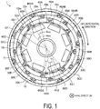
- FIG. 1 is a top view illustrating an example of a motor according to an embodiment.
- the motor 1 illustrated in FIG. 1 includes, for example, a stator 2, a rotor 70, and a shaft 80.
- the motor 1 to be described in each embodiment is, for example, an inner rotor type brushless motor.
- the rotor 70 including a plurality of magnets 71 as constituent parts is disposed at the motor 1, and a rotating shaft (shaft) 80 is fixed to the rotor 70.
- the motor 1 is housed in a frame (not illustrated), for example.
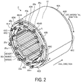
- FIG. 2 is a perspective view illustrating an example of the stator according to the embodiment.
- the stator 2 according to the embodiment includes a yoke 10, a plurality of first coils 40A to 40H, a plurality of second coils 50A to 50H, and a plurality of third coils 60A to 60H.
- first coils 40A to 40H when the plurality of first coils 40A to 40H are represented without distinction, the first coils 40A to 40H may be simply referred to as first coils 40.
- the plurality of second coils 50A to 50H and the plurality of third coils 60A to 60H may be simply referred to as air core coils X0.
- the motor 1 according to the embodiment is, for example, a motor with 8 poles and 24 slots. That is, the motor 1 according to the embodiment includes the eight magnets 71 and the 24 air core coils X0 as illustrated in FIG. 1 .
- the stator 2 is formed of, for example, a magnetic body such as stainless steel or a magnetic steel sheet, and includes the yoke 10 having a cylindrical shape and opened in the direction of the rotating shaft, and magnetic pole parts 20.
- an insulator is formed at the surface of the yoke 10 according to the embodiment by electrodeposition coating.
- the yoke 10 includes 24 magnetic pole parts 20a to 20x extending in the axial direction.
- the magnetic pole parts 20a to 20x may be simply referred to as the magnetic pole parts 20.
- the magnetic pole parts 20 are protruding parts integrally formed with the yoke 10 and protruding inward in a radial direction from an inner peripheral surface side of the yoke 10.
- the magnetic pole parts 20 have a shape having no end part protruding in the circumferential direction at a distal end side (inside in the radial direction).
- the 24 magnetic pole parts 20 are arranged side by side at equal intervals in the circumferential direction.
- an angle Rxa between the magnetic pole part 20a and the magnetic pole part 20x adjacent to each other in the circumferential direction is about 15°.
- an angle Rwx between the magnetic pole part 20w and the magnetic pole part 20x adjacent to each other in the circumferential direction is also about 15°.
- a plurality of the first coils 40, a plurality of the second coils 50, and a plurality of the third coils 60 are disposed at the magnetic pole parts 20.
- the first coils 40, the second coils 50, and the third coils 60 are, for example, pre-wound air core coils.
- the first coils 40 are examples of air core coils of a first group
- the second coils 50 are examples of air core coils of a second group
- the third coils 60 are examples of air core coils of a third group.
- the air core coil X0 is formed, for example, by bending a conducting wire (for example, a flat wire or a round wire) formed of a conductor such as copper.
- the conductor of the conducting wire forming the air core coil X0 is covered with, for example, a coating layer formed of a heat-resistant resin such as polyimide.
- the conducting wire forming the air core coil X0 may be a self-fusion wire obtained by covering the coating layer with a fusion layer.
- the fusion layer is formed of a resin capable of forming a film by being melted by heat or a solvent.
- the air core coil X0 has a shape curved in the circumferential direction.
- the first coil 40 is formed into a shape curved along the inner peripheral surface of the yoke 10 in the circumferential direction.
- the second coil 50 disposed inside the first coil 40 is formed to have a larger curvature in the circumferential direction and a smaller width in the circumferential direction than the first coil 40.
- the third coil 60 is formed to have a larger curvature in the circumferential direction and a smaller width in the circumferential direction than the second coil 50.
- lengths of the first coil 40, the second coil 50, and the third coil 60 in the axial direction are substantially the same.
- FIG. 3 is a perspective view illustrating an example of the first coil according to the embodiment. In FIG. 3 , the magnetic pole parts 20 are not illustrated.
- a winding start 41A and a winding end 42A of the first coil 40A and a winding start 41B and a winding end 42B of the first coil 40B protrude toward a negative direction side in the axial direction (the other end part side of the yoke 10).
- the winding starts 41A and 41B and the winding ends 42A and 42B are examples of connection end parts.
- the conducting wires of the two air core coils X0 adjacent to each other are wound in opposite directions.
- the conducting wire of the first coil 40B is wound counterclockwise (CCW) from the winding start 41B toward the winding end 42B
- the conducting wire of the first coil 40A adjacent to the first coil 40B in the circumferential direction is wound clockwise (CW) from the winding start 41A to the winding end 42A.
- the first coils 40A, 40C, 40E and 40G are wound clockwise and the other first coils 40B, 40D, 40F and 40H are counterclockwise. Accordingly, a N-pole coil and a S-pole coil are adjacent to each other in the circumferential direction.
- winding starts from the same direction in the circumferential direction and ends in the same direction. That is, in the two first coils 40 adjacent to each other in the circumferential direction, for example, the winding start 41B of the first coil 40B and the winding end 42A of the first coil 40A are close to each other, and the winding start 41A of the first coil 40A and the winding end 42B of the first coil 40B are far from each other.
- Each air core coil X0 is formed into a substantially arc shape when viewed from the top (axial direction side).
- the winding start 41A and the winding end 42A of the first coil 40A and the winding start 41B and the winding end 42B of the first coil 40B protrude toward the negative direction side in the axial direction.
- each air core coil X0 may also protrude in the circumferential direction or the axial direction.
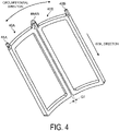
- FIG. 4 is a perspective view illustrating an example of bonding the first coils according to the embodiment. Also in FIG. 4 , the magnetic pole parts 20 are not illustrated.
- the air core coils X0 adjacent to each other in the circumferential direction are bonded by bonding parts 49, 59, or 69.
- the first coil 40A and the first coil 40B adjacent to the first coil 40A are electrically connected by a bonding part 49AB.
- the bonding part 49AB is formed by, for example, welding or ultrasonically bonding the winding end 42A of the first coil 40A and the winding start 41B of the first coil 40B.
- some of the bonding parts may not be illustrated.
- the first coils 40A and 40B adjacent to each other in the circumferential direction are separated at portions other than the bonding parts 49AB.
- a gap G1 is formed between the first coil 40A and the first coil 40B.
- portions other than the connection end part may be insulated from each other by an insulating member such as a resin (not illustrated). The insulating member may be provided in the gap G1.
- the above configuration of the first coil 40 illustrated in FIG. 3 and FIG. 4 also applies to the second coil 50 and the third coil 60 with some exceptions.
- the second coil 50A and the second coil 50B adjacent to each other in the circumferential direction and the third coil 60D and the third coil 60E adjacent to each other in the circumferential direction are also electrically connected by the bonding parts 59AB and 69DE illustrated in FIG. 1 , respectively.
- the second coil 50 located, in the circumferential direction, between the first coil 40 and the third coil 60 wound in the same direction is wound in an opposite direction.
- the third coils 60A, 60C, 60E and 60G are wound clockwise and the other third coils 60B, 60D, 60F and 60H are wound counterclockwise.
- a conducting wire is wound counterclockwise (CCW) in the second coil 50A located between the first coil 40A and the third coil 60A including conducting wires wound clockwise (CW). That is, the second coils 50B, 50D, 50F, and 50H are wound clockwise, and the other second coils 50A, 50C, 50E, and 50G are wound counterclockwise.
- the first coils 40, the second coils 50, and the third coils 60 are disposed at positions different from each other in the circumferential direction.
- an angle R12 between the first coil 40E and the second coil 50E is about 15°.
- an angle R23 between the second coil 50E and the third coil 60E and an angle R31 between the first coil 40E and the third coil 60D are also about 15°.
- a part of the first coil 40 opposes parts of the two second coils 50 and the two third coils 60 in the radial direction.
- a part of the first coil 40F opposes parts of the second coils 50E and 50F and opposes parts of the third coils 60E and 60F in the radial direction.
- a part of the second coil 50E opposes parts of the first coils 40E and 40F and opposes parts of the third coils 60D and 60E
- a part of the third coil 60E opposes parts of the first coils 40E and 40F and opposes parts of the second coils 50E and 50F.
- FIG. 5 is a cross-sectional perspective view illustrating an example of the stator according to the embodiment.
- FIG. 5 illustrates a cross section taken along line A-A in FIG. 2 .
- the second coil 50H and the second coil 50A are adjacent to each other in the circumferential direction without interposing another air core coil X0 or magnetic pole part 20.
- the third coil 60H and the third coil 60A are also adjacent to each other in the circumferential direction without interposing another air core coil X0 or magnetic pole part 20.
- the first coil 40A, an arc part (curved part) of the third coil 60H, and an arc part (curved part) of the third coil 60A are not visible.
- the magnetic pole part 20a is disposed inside the second coil 50H and inside the third coil 60H in the circumferential direction.
- the magnetic pole part 20a is disposed inside the first coil 40A in the radial direction.
- the other magnetic pole parts 20b to 20x are also disposed inside at least any of the first coils 40, the second coils 50, and the third coils 60 in the circumferential direction.
- the eight first coils 40A to 40H arranged in a substantially circular pattern in the circumferential direction form a first row C1.
- the eight second coils 50A to 50H arranged in a substantially circular pattern in the circumferential direction form a second row C2
- the eight third coils 60A to 60H arranged in a substantially circular pattern in the circumferential direction form a third row C3.
- the first row C1, the second row C2, and the third row C3 form a substantially concentric circle centered around the shaft 80. That is, the first coils 40A to 40H are disposed so that distances in the radial direction from the shaft 80 are substantially the same. Furthermore, the second coils 50A to 50H are disposed inside the first row C1 in the radial direction, and the third coils 60A to 60H are disposed inside the first columns C1 and the second row C2 in the radial direction.
- the first coils 40, the second coils 50, and the third coils 60 correspond to a U phase, a V phase, and a W phase of the motor 1, respectively.
- the arrangement of the U phase, the V phase, and the W phase is an example, and the order may be different from the order of the example described in the embodiment.
- the air core coils X0 are disposed at the magnetic pole parts 20 in the order of the first coils 40, the second coils 50, and the third coils 60.
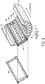
- FIG. 6 is a cross-sectional perspective view illustrating an example of mounting the first coil according to the embodiment.
- FIG. 7 is a cross-sectional perspective view illustrating an example of mounting the second coil according to the embodiment.
- FIG. 8 is a cross-sectional perspective view illustrating an example of mounting the third coil according to the embodiment.
- FIG. 6 to FIG. 8 illustrate cross sections taken along line B-B in FIG. 2 .
- the air core coils X0 are disposed, for example, after the magnetic pole parts 20 are covered with an annular insulating member (not illustrated).
- the first coil 40F is disposed in contact with the magnetic pole parts 20p and 20r among the 24 magnetic pole parts 20.
- the magnetic pole part 20q adjacent to the magnetic pole part 20p and the magnetic pole part 20r in the circumferential direction is also disposed inside the first coil 40F. That is, the three magnetic pole parts 20p, 20q, and 20r are disposed inside the first coil 40F.
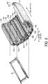
- the other first coils 40A to 40E, 40G, and 40H are similarly disposed.
- the second coil 50 is disposed, in the radial direction, inside the first coil 40 disposed at the magnetic pole parts 20.
- the second coil 50F is disposed at a position different from the positions of the first coils 40F and 40G in the circumferential direction, the first coils 40F and 40G being adjacent to the second coil 50F in the radial direction.
- the magnetic pole parts 20q, 20r and 20s disposed inside the second coil 50F in the circumferential direction only the magnetic pole parts 20q and 20r are disposed inside the first coil 40F.
- the magnetic pole part 20s is disposed inside the first coil 40G, not inside the first coil 40F. That is, the second coil 50 is disposed across the two first coils 40 in the circumferential direction.
- the third coil 60 is disposed, in the radial direction, inside the second coil 50 disposed at the magnetic pole parts 20.
- the third coil 60E is disposed at a position different from the positions of the second coils 50E and 50F in the circumferential direction, the second coils 50E and 50F being adjacent to the third coil 60E in the radial direction.
- the third coil 60E is disposed at a position different from the position of any of the first coils 40 in the circumferential direction.
- the magnetic pole part 20o is disposed at the first coil 40E, while the magnetic pole parts 20p and 20q are disposed at the first coil 40F. That is, the third coil 60 is disposed across the two first coils 40 and across the two second coils 50 in the circumferential direction.
- Each magnetic pole part 20 is disposed inside at least one air core coil X0 in the circumferential direction. Furthermore, in the embodiment, each air core coil X0 is disposed across a plurality of the magnetic pole parts 20 in the circumferential direction.
- the magnetic pole part 20b is disposed inside the first coil 40A, inside the second coil 50A, and inside the third coil 60H in the circumferential direction.
- the eight first coils 40 are disposed at the first row C1
- the eight second coils 50 are disposed at the second row C2
- the eight third coils 60 are disposed at the third column C3.
- stoppers may be further mounted at both sides of the stator 2 in the axial direction.
- the motor 1 includes the yoke 10 including the plurality of magnetic pole parts 20 arranged in the circumferential direction, and the plurality of air core coils 40, 50, and 60 arranged in the circumferential direction.
- the plurality of magnetic pole parts 20 are disposed inside any of the plurality of air core coils 40, 50, and 60.
- connection end parts drawn from two adjacent air core coils are electrically connected to each other. According to such a configuration, the configuration of the motor can be simplified and man-hours in manufacturing can be reduced.
- the height of a coil end protruding from the yoke 10 in the axial direction can be reduced. Furthermore, according to such a configuration, the two adjacent air core coils X0 can be connected, so that the number of parts can be reduced, a resistance value of the entire motor can be reduced, and power consumption can be reduced.
- each of the embodiments has been described above, but the embodiments are not limited.
- the motor according to each embodiment is not limited to a motor with 8 poles and 24 slots, and the number of coils and the number of magnets may be changed.
- the example of disposing the air core coil X0 across the three magnetic pole parts 20 has been described, but the embodiment is not limited to this example.
- the air core coil X0 may be disposed across the two magnetic pole parts 20, or may be disposed across the four or more magnetic pole parts 20.
- the number of rows of the air core coils X0 is also freely determined, and a configuration of not forming the third column C3 or a configuration of further forming a fourth column C4 may be available.
- the embodiment is not limited to this configuration, and the air core coils X0 may be configured to be adjacent to each other at predetermined intervals in the circumferential direction.
- the motor according to each embodiment is, for example, an inner rotor type brushless motor, but the embodiment is not limited to the inner rotor type brushless motor, and the air core coil X0 according to the embodiment may be employed in an outer rotor type motor.
- the stator 2 including the air core coils X0 may be employed in, for example, a rotary electric machine other than a motor, such as a generator.
- the magnetic pole part 20 may be shaped to include two end parts protruding in the circumferential direction, for example, at a distal end side (inside in the radial direction).
- the configuration of forming the air core coil X0 by using a self-fusion wire has been described, but the embodiment is not limited to this configuration and, for example, a coil wound by using a bobbin may be covered with a resin material such as a varnish.
Landscapes
- Engineering & Computer Science (AREA)
- Power Engineering (AREA)
- Windings For Motors And Generators (AREA)
- Manufacture Of Motors, Generators (AREA)
Abstract
Description
- The present invention relates to a motor.
- A distributed winding technique of disposing a coil across a plurality of magnetic pole parts is known in a rotary electric machine such as a motor. In the distributed winding technique, for example, it is known to use a segment coil.
-
- Patent Document 1:
JP 2015-6082 A - Patent Document 2:
JP 2015-223028 A - Patent Document 3:
JP 2016-73120 A - Since the segment coil requires a lot of man-hours for forming and welding rectangular wires, the configuration of a motor is complicated. Furthermore, a coil end protruding in an axial direction hinders the miniaturization of a motor.
- An object of one aspect is to simplify the configuration of a motor.
- In one aspect, a motor includes a yoke including a plurality of magnetic pole parts arranged in a circumferential direction, and a plurality of air core coils arranged in the circumferential direction. The plurality of magnetic pole parts are disposed inside any of the plurality of air core coils in the circumferential direction. Among the plurality of air core coils, connection end parts drawn from two adjacent air core coils are electrically connected to each other.
- According one aspect, the configuration of a motor can be simplified.
-
-
FIG. 1 is a top view illustrating an example of a motor according to an embodiment. -
FIG. 2 is a perspective view illustrating an example of a stator according to the embodiment. -
FIG. 3 is a perspective view illustrating an example of a first coil according to the embodiment. -
FIG. 4 is a perspective view illustrating an example of bonding the first coil according to the embodiment. -
FIG. 5 is a cross-sectional perspective view illustrating an example of the stator according to the embodiment. -
FIG. 6 is a cross-sectional perspective view illustrating an example of mounting the first coil according to the embodiment. -
FIG. 7 is a cross-sectional perspective view illustrating an example of mounting a second coil according to the embodiment. -
FIG. 8 is a cross-sectional perspective view illustrating an example of mounting a third coil according to the embodiment. - An embodiment of a motor disclosed in the present application will be described below in detail with reference to the drawings. Note that the dimensional relationships, the proportions, and the like between elements in the drawings may differ from those in reality. Among the drawings, parts having mutually different dimensional relationships and proportions may be included. In order to facilitate a description, each drawing may illustrate a coordinate system. In the coordinate system, an extending direction of a
shaft 80 to be described below is defined as an axial direction and a rotation direction of arotor 70 is defined as a circumferential direction. -
FIG. 1 is a top view illustrating an example of a motor according to an embodiment. Themotor 1 illustrated inFIG. 1 includes, for example, astator 2, arotor 70, and ashaft 80. Themotor 1 to be described in each embodiment is, for example, an inner rotor type brushless motor. For example, therotor 70 including a plurality ofmagnets 71 as constituent parts is disposed at themotor 1, and a rotating shaft (shaft) 80 is fixed to therotor 70. Furthermore, themotor 1 is housed in a frame (not illustrated), for example. -
FIG. 2 is a perspective view illustrating an example of the stator according to the embodiment. As illustrated inFIG. 1 andFIG. 2 , thestator 2 according to the embodiment includes ayoke 10, a plurality offirst coils 40A to 40H, a plurality ofsecond coils 50A to 50H, and a plurality ofthird coils 60A to 60H. In the following, when the plurality offirst coils 40A to 40H are represented without distinction, thefirst coils 40A to 40H may be simply referred to asfirst coils 40. The same applies to the plurality ofsecond coils 50A to 50H and the plurality ofthird coils 60A to 60H. Furthermore, in the following, when thefirst coils 40, thesecond coils 50, and thethird coils 60 are represented without distinction, thefirst coils 40, thesecond coils 50, and thethird coils 60 may be simply referred to as air core coils X0. - The
motor 1 according to the embodiment is, for example, a motor with 8 poles and 24 slots. That is, themotor 1 according to the embodiment includes the eightmagnets 71 and the 24 air core coils X0 as illustrated inFIG. 1 . - The
stator 2 is formed of, for example, a magnetic body such as stainless steel or a magnetic steel sheet, and includes theyoke 10 having a cylindrical shape and opened in the direction of the rotating shaft, and magnetic pole parts 20. For example, an insulator is formed at the surface of theyoke 10 according to the embodiment by electrodeposition coating. Furthermore, theyoke 10 includes 24magnetic pole parts 20a to 20x extending in the axial direction. In the following, when the plurality ofmagnetic pole parts 20a to 20x are represented without distinction, themagnetic pole parts 20a to 20x may be simply referred to as the magnetic pole parts 20. - The magnetic pole parts 20 are protruding parts integrally formed with the
yoke 10 and protruding inward in a radial direction from an inner peripheral surface side of theyoke 10. In the embodiment, as illustrated inFIG. 2 , the magnetic pole parts 20 have a shape having no end part protruding in the circumferential direction at a distal end side (inside in the radial direction). - In the embodiment, the 24 magnetic pole parts 20 are arranged side by side at equal intervals in the circumferential direction. For example, as illustrated in
FIG. 1 andFIG. 2 , an angle Rxa between themagnetic pole part 20a and themagnetic pole part 20x adjacent to each other in the circumferential direction is about 15°. Similarly, an angle Rwx between themagnetic pole part 20w and themagnetic pole part 20x adjacent to each other in the circumferential direction is also about 15°. - A plurality of the
first coils 40, a plurality of thesecond coils 50, and a plurality of thethird coils 60 are disposed at the magnetic pole parts 20. Thefirst coils 40, thesecond coils 50, and thethird coils 60 are, for example, pre-wound air core coils. Thefirst coils 40 are examples of air core coils of a first group, thesecond coils 50 are examples of air core coils of a second group, and thethird coils 60 are examples of air core coils of a third group. - The air core coil X0 is formed, for example, by bending a conducting wire (for example, a flat wire or a round wire) formed of a conductor such as copper. In the embodiment, the conductor of the conducting wire forming the air core coil X0 is covered with, for example, a coating layer formed of a heat-resistant resin such as polyimide. Furthermore, the conducting wire forming the air core coil X0 may be a self-fusion wire obtained by covering the coating layer with a fusion layer. The fusion layer is formed of a resin capable of forming a film by being melted by heat or a solvent.
- The air core coil X0 has a shape curved in the circumferential direction. For example, the
first coil 40 is formed into a shape curved along the inner peripheral surface of theyoke 10 in the circumferential direction. Furthermore, in the radial direction, thesecond coil 50 disposed inside the first coil 40 (at therotor 70 side) is formed to have a larger curvature in the circumferential direction and a smaller width in the circumferential direction than thefirst coil 40. Similarly, thethird coil 60 is formed to have a larger curvature in the circumferential direction and a smaller width in the circumferential direction than thesecond coil 50. In the embodiment, lengths of thefirst coil 40, thesecond coil 50, and thethird coil 60 in the axial direction are substantially the same. - In the embodiment, for example, both a winding start and a winding end of the air core coil X0 protrude to the outside of the
yoke 10 to form lead wires. That is, the conducting wire of the air core coil X0 is wound to have a so-called alpha (α) shape.FIG. 3 is a perspective view illustrating an example of the first coil according to the embodiment. InFIG. 3 , the magnetic pole parts 20 are not illustrated. - As illustrated in
FIG. 3 , a windingstart 41A and a windingend 42A of thefirst coil 40A and a windingstart 41B and a windingend 42B of thefirst coil 40B protrude toward a negative direction side in the axial direction (the other end part side of the yoke 10). The winding starts 41A and 41B and the winding ends 42A and 42B are examples of connection end parts. - In the embodiment, the conducting wires of the two air core coils X0 adjacent to each other are wound in opposite directions. For example, as illustrated in
FIG. 3 , when the conducting wire of thefirst coil 40B is wound counterclockwise (CCW) from the windingstart 41B toward the windingend 42B, the conducting wire of thefirst coil 40A adjacent to thefirst coil 40B in the circumferential direction is wound clockwise (CW) from the windingstart 41A to the windingend 42A. - In the embodiment, among the eight
first coils 40, thefirst coils first coils - Furthermore, as illustrated in
FIG. 3 , in thefirst coil 40A wound counterclockwise and thefirst coil 40B wound clockwise, winding starts from the same direction in the circumferential direction and ends in the same direction. That is, in the twofirst coils 40 adjacent to each other in the circumferential direction, for example, the windingstart 41B of thefirst coil 40B and the windingend 42A of thefirst coil 40A are close to each other, and the windingstart 41A of thefirst coil 40A and the windingend 42B of thefirst coil 40B are far from each other. - Each air core coil X0 is formed into a substantially arc shape when viewed from the top (axial direction side). In this case, as illustrated in
FIG. 3 , the windingstart 41A and the windingend 42A of thefirst coil 40A and the windingstart 41B and the windingend 42B of thefirst coil 40B protrude toward the negative direction side in the axial direction. If necessary, each air core coil X0 may also protrude in the circumferential direction or the axial direction. - Furthermore, in the embodiment, after the air core coils X0 are disposed at the magnetic pole parts 20, the winding starts and the winding ends of the air core coils X0 adjacent to each other are electrically connected.
FIG. 4 is a perspective view illustrating an example of bonding the first coils according to the embodiment. Also inFIG. 4 , the magnetic pole parts 20 are not illustrated. - In the embodiment, the air core coils X0 adjacent to each other in the circumferential direction are bonded by bonding parts 49, 59, or 69. For example, as illustrated in
FIG. 4 , thefirst coil 40A and thefirst coil 40B adjacent to thefirst coil 40A are electrically connected by a bonding part 49AB. The bonding part 49AB is formed by, for example, welding or ultrasonically bonding the windingend 42A of thefirst coil 40A and the windingstart 41B of thefirst coil 40B. InFIG. 1 ,FIG. 2 , andFIG. 5 , some of the bonding parts may not be illustrated. - Furthermore, in the embodiment, as illustrated in
FIG. 4 , thefirst coils first coil 40A and thefirst coil 40B. In the two air core coils X0 adjacent to each other in the circumferential direction, portions other than the connection end part may be insulated from each other by an insulating member such as a resin (not illustrated). The insulating member may be provided in the gap G1. - In the embodiment, the above configuration of the
first coil 40 illustrated inFIG. 3 andFIG. 4 also applies to thesecond coil 50 and thethird coil 60 with some exceptions. For example, thesecond coil 50A and thesecond coil 50B adjacent to each other in the circumferential direction and thethird coil 60D and thethird coil 60E adjacent to each other in the circumferential direction are also electrically connected by the bonding parts 59AB and 69DE illustrated inFIG. 1 , respectively. - However, in the embodiment, the
second coil 50 located, in the circumferential direction, between thefirst coil 40 and thethird coil 60 wound in the same direction is wound in an opposite direction. For example, similarly to thefirst coil 40, thethird coils third coils second coil 50A located between thefirst coil 40A and thethird coil 60A including conducting wires wound clockwise (CW). That is, thesecond coils second coils - Furthermore, in the embodiment, the first coils 40, the second coils 50, and the
third coils 60 are disposed at positions different from each other in the circumferential direction. For example, as illustrated inFIG. 1 , in the circumferential direction, an angle R12 between thefirst coil 40E and thesecond coil 50E is about 15°. Similarly, an angle R23 between thesecond coil 50E and thethird coil 60E and an angle R31 between thefirst coil 40E and thethird coil 60D are also about 15°. - In this case, in the embodiment, a part of the
first coil 40 opposes parts of the twosecond coils 50 and the twothird coils 60 in the radial direction. For example, as illustrated inFIG. 5 , a part of thefirst coil 40F opposes parts of thesecond coils third coils second coil 50E opposes parts of thefirst coils third coils third coil 60E opposes parts of thefirst coils second coils -
FIG. 5 is a cross-sectional perspective view illustrating an example of the stator according to the embodiment.FIG. 5 illustrates a cross section taken along line A-A inFIG. 2 . As illustrated inFIG. 5 , thesecond coil 50H and thesecond coil 50A are adjacent to each other in the circumferential direction without interposing another air core coil X0 or magnetic pole part 20. Similarly, thethird coil 60H and thethird coil 60A are also adjacent to each other in the circumferential direction without interposing another air core coil X0 or magnetic pole part 20. InFIG. 5 , thefirst coil 40A, an arc part (curved part) of thethird coil 60H, and an arc part (curved part) of thethird coil 60A are not visible. - Furthermore, as illustrated in
FIG. 5 , themagnetic pole part 20a is disposed inside thesecond coil 50H and inside thethird coil 60H in the circumferential direction. Similarly, as illustrated inFIG. 2 , themagnetic pole part 20a is disposed inside thefirst coil 40A in the radial direction. Similarly, the othermagnetic pole parts 20b to 20x are also disposed inside at least any of the first coils 40, the second coils 50, and thethird coils 60 in the circumferential direction. - As illustrated in
FIG. 5 , the eightfirst coils 40A to 40H arranged in a substantially circular pattern in the circumferential direction form a first row C1. Similarly, the eightsecond coils 50A to 50H arranged in a substantially circular pattern in the circumferential direction form a second row C2, and the eightthird coils 60A to 60H arranged in a substantially circular pattern in the circumferential direction form a third row C3. - The first row C1, the second row C2, and the third row C3 form a substantially concentric circle centered around the
shaft 80. That is, thefirst coils 40A to 40H are disposed so that distances in the radial direction from theshaft 80 are substantially the same. Furthermore, thesecond coils 50A to 50H are disposed inside the first row C1 in the radial direction, and thethird coils 60A to 60H are disposed inside the first columns C1 and the second row C2 in the radial direction. - Furthermore, in the embodiment, the first coils 40, the second coils 50, and the
third coils 60 correspond to a U phase, a V phase, and a W phase of themotor 1, respectively. The arrangement of the U phase, the V phase, and the W phase is an example, and the order may be different from the order of the example described in the embodiment. - In the embodiment, the air core coils X0 are disposed at the magnetic pole parts 20 in the order of the first coils 40, the second coils 50, and the third coils 60.
FIG. 6 is a cross-sectional perspective view illustrating an example of mounting the first coil according to the embodiment.FIG. 7 is a cross-sectional perspective view illustrating an example of mounting the second coil according to the embodiment.FIG. 8 is a cross-sectional perspective view illustrating an example of mounting the third coil according to the embodiment.FIG. 6 to FIG. 8 illustrate cross sections taken along line B-B inFIG. 2 . In the embodiment, the air core coils X0 are disposed, for example, after the magnetic pole parts 20 are covered with an annular insulating member (not illustrated). - As illustrated in
FIG. 6 , thefirst coil 40F is disposed in contact with themagnetic pole parts magnetic pole part 20q adjacent to themagnetic pole part 20p and themagnetic pole part 20r in the circumferential direction is also disposed inside thefirst coil 40F. That is, the threemagnetic pole parts first coil 40F. The otherfirst coils 40A to 40E, 40G, and 40H are similarly disposed. - Furthermore, as illustrated in
FIG. 7 , thesecond coil 50 is disposed, in the radial direction, inside thefirst coil 40 disposed at the magnetic pole parts 20. At this time, as illustrated inFIG. 7 , thesecond coil 50F is disposed at a position different from the positions of thefirst coils first coils second coil 50F in the radial direction. - For example, among the three
magnetic pole parts second coil 50F in the circumferential direction, only themagnetic pole parts first coil 40F. Themagnetic pole part 20s is disposed inside thefirst coil 40G, not inside thefirst coil 40F. That is, thesecond coil 50 is disposed across the twofirst coils 40 in the circumferential direction. - Similarly, as illustrated in
FIG. 8 , thethird coil 60 is disposed, in the radial direction, inside thesecond coil 50 disposed at the magnetic pole parts 20. At this time, as illustrated inFIG. 8 , thethird coil 60E is disposed at a position different from the positions of thesecond coils second coils third coil 60E in the radial direction. Furthermore, thethird coil 60E is disposed at a position different from the position of any of thefirst coils 40 in the circumferential direction. - For example, among the three
magnetic pole parts third coil 60E in the circumferential direction, only themagnetic pole parts 20o and 20p are disposed inside thesecond coil 50E, and themagnetic pole part 20r is disposed inside thesecond coil 50F. Furthermore, among the three magnetic pole parts, the magnetic pole part 20o is disposed at thefirst coil 40E, while themagnetic pole parts first coil 40F. That is, thethird coil 60 is disposed across the twofirst coils 40 and across the twosecond coils 50 in the circumferential direction. - Each magnetic pole part 20 is disposed inside at least one air core coil X0 in the circumferential direction. Furthermore, in the embodiment, each air core coil X0 is disposed across a plurality of the magnetic pole parts 20 in the circumferential direction. For example, the
magnetic pole part 20b is disposed inside thefirst coil 40A, inside thesecond coil 50A, and inside thethird coil 60H in the circumferential direction. - As described above, the eight
first coils 40 are disposed at the first row C1, the eightsecond coils 50 are disposed at the second row C2, and the eightthird coils 60 are disposed at the third column C3. As to thestator 2 where all the air core coils X0 are disposed, stoppers (not illustrated) may be further mounted at both sides of thestator 2 in the axial direction. - As described above, the
motor 1 according to the embodiment includes theyoke 10 including the plurality of magnetic pole parts 20 arranged in the circumferential direction, and the plurality of air core coils 40, 50, and 60 arranged in the circumferential direction. The plurality of magnetic pole parts 20 are disposed inside any of the plurality of air core coils 40, 50, and 60. Among the plurality of air core coils 40, 50, and 60, connection end parts drawn from two adjacent air core coils are electrically connected to each other. According to such a configuration, the configuration of the motor can be simplified and man-hours in manufacturing can be reduced. - Furthermore, according to such a configuration, the height of a coil end protruding from the
yoke 10 in the axial direction can be reduced. Furthermore, according to such a configuration, the two adjacent air core coils X0 can be connected, so that the number of parts can be reduced, a resistance value of the entire motor can be reduced, and power consumption can be reduced. - The configuration of each of the embodiments has been described above, but the embodiments are not limited. For example, the motor according to each embodiment is not limited to a motor with 8 poles and 24 slots, and the number of coils and the number of magnets may be changed. Furthermore, the example of disposing the air core coil X0 across the three magnetic pole parts 20 has been described, but the embodiment is not limited to this example. For example, the air core coil X0 may be disposed across the two magnetic pole parts 20, or may be disposed across the four or more magnetic pole parts 20. Furthermore, the number of rows of the air core coils X0 is also freely determined, and a configuration of not forming the third column C3 or a configuration of further forming a fourth column C4 may be available.
- Moreover, the configuration where the air core coils X0 adjacent to each other in the circumferential direction are directly adjacent to each other without interposing another magnetic pole part 20 has been described, but the embodiment is not limited to this configuration, and the air core coils X0 may be configured to be adjacent to each other at predetermined intervals in the circumferential direction.
- Furthermore, the motor according to each embodiment is, for example, an inner rotor type brushless motor, but the embodiment is not limited to the inner rotor type brushless motor, and the air core coil X0 according to the embodiment may be employed in an outer rotor type motor. Furthermore, the
stator 2 including the air core coils X0 may be employed in, for example, a rotary electric machine other than a motor, such as a generator. - Furthermore, when there is no problem in the arrangement of the air core coils X0, the magnetic pole part 20 may be shaped to include two end parts protruding in the circumferential direction, for example, at a distal end side (inside in the radial direction).
- Furthermore, the configuration of forming the air core coil X0 by using a self-fusion wire has been described, but the embodiment is not limited to this configuration and, for example, a coil wound by using a bobbin may be covered with a resin material such as a varnish.
- Embodiments and modified examples of the present invention have been described, but the present invention is not limited to the embodiments and modified examples, and various modifications are possible without departing from the spirit of the present invention. Various modifications within a scope not departing from the gist are included in the technical scope of the present invention, and this is obvious to a person having skill in the art from the description of the claims.
- 1 Motor, 2 Stator, 10 Yoke, 20 Magnetic pole part, 40 First coil, 50 Second coil, 60 Third coil, 49, 59, 69 Bonding part
Claims (6)
- A motor (1) comprising:a yoke (10) including a plurality of magnetic pole parts (20) arranged in a circumferential direction; anda plurality of air core coils (40, 50, 60) arranged in the circumferential direction, whereinthe plurality of magnetic pole parts (20) are disposed inside any of the plurality of air core coils (40, 50, 60) in the circumferential direction, andamong the plurality of air core coils (40, 50, 60), connection end parts drawn from two adjacent air core coils (40, 50, 60) are electrically connected to each other.
- The motor (1) according to claim 1, wherein winding directions of the two adjacent air core coils (40, 50, 60) are opposite to each other.
- The motor (1) according to claim 1 or 2, wherein
among the plurality of air core coils (40, 50, 60), air core coils (40) of a first group forming a first row (C1) in a radial direction form a U phase, air core coils (50) of a second group forming a second row (C2) in the radial direction form a V phase, and air core coils (60) of a third group forming a third row (C3) in the radial direction form a W phase. - The motor (1) according to claim 3, wherein the air core coils (40) of the first group, the air core coils (50) of the second group, and the air core coils (60) of the third group are arranged at positions different from each other in the circumferential direction.
- The motor (1) according to claim 3 or 4, wherein the air core coils (40) of the first group are not adjacent to the air core coils (50) of the second group nor the air core coils (60) of the third group in the circumferential direction.
- The motor (1) according to any one of claims 1 to 5, wherein the air core coils (40, 50, 60) are disposed across two or more magnetic pole parts (20) among the plurality of magnetic pole parts (20).
Applications Claiming Priority (1)
| Application Number | Priority Date | Filing Date | Title |
|---|---|---|---|
| JP2021093421A JP7814112B2 (en) | 2021-06-03 | 2021-06-03 | motor |
Publications (1)
| Publication Number | Publication Date |
|---|---|
| EP4099545A1 true EP4099545A1 (en) | 2022-12-07 |
Family
ID=81854701
Family Applications (1)
| Application Number | Title | Priority Date | Filing Date |
|---|---|---|---|
| EP22176288.3A Pending EP4099545A1 (en) | 2021-06-03 | 2022-05-31 | Motor |
Country Status (3)
| Country | Link |
|---|---|
| EP (1) | EP4099545A1 (en) |
| JP (1) | JP7814112B2 (en) |
| CN (1) | CN115441620A (en) |
Citations (5)
| Publication number | Priority date | Publication date | Assignee | Title |
|---|---|---|---|---|
| US20050006977A1 (en) * | 2003-05-21 | 2005-01-13 | Raffaele Becherucci | Apparatus and methods for winding dynamo-electric machine components |
| JP2015006082A (en) | 2013-06-21 | 2015-01-08 | 東芝産業機器システム株式会社 | Stator of rotary electric machine |
| JP2015223028A (en) | 2014-05-22 | 2015-12-10 | アイシン・エィ・ダブリュ株式会社 | Stator for rotary electric machine |
| JP2016073120A (en) | 2014-09-30 | 2016-05-09 | アイシン・エィ・ダブリュ株式会社 | Stator for rotary electric machine |
| US20190363596A1 (en) * | 2017-01-30 | 2019-11-28 | Kesatoshi Takeuchi | Coreless electric machine, and method of manufacturing coreless electric machine |
Family Cites Families (5)
| Publication number | Priority date | Publication date | Assignee | Title |
|---|---|---|---|---|
| JP4558000B2 (en) * | 2007-05-01 | 2010-10-06 | スミダ電機株式会社 | Continuous winding coil and stator |
| JP5033668B2 (en) * | 2008-02-14 | 2012-09-26 | 日立オートモティブシステムズ株式会社 | Rotating electric machine |
| WO2014030214A1 (en) * | 2012-08-21 | 2014-02-27 | 株式会社安川電機 | Coil, rotating electrical machine, and method of manufacturing coil |
| JP2016208745A (en) * | 2015-04-24 | 2016-12-08 | 株式会社安川電機 | Rotary electric machine, method for manufacturing rotary electric machine, stator coil, and coil resin structure |
| JP2020145853A (en) * | 2019-03-06 | 2020-09-10 | 日本精工株式会社 | Air-core coil and air-core coil manufacturing method and stator |
-
2021
- 2021-06-03 JP JP2021093421A patent/JP7814112B2/en active Active
-
2022
- 2022-05-17 CN CN202210538659.7A patent/CN115441620A/en active Pending
- 2022-05-31 EP EP22176288.3A patent/EP4099545A1/en active Pending
Patent Citations (5)
| Publication number | Priority date | Publication date | Assignee | Title |
|---|---|---|---|---|
| US20050006977A1 (en) * | 2003-05-21 | 2005-01-13 | Raffaele Becherucci | Apparatus and methods for winding dynamo-electric machine components |
| JP2015006082A (en) | 2013-06-21 | 2015-01-08 | 東芝産業機器システム株式会社 | Stator of rotary electric machine |
| JP2015223028A (en) | 2014-05-22 | 2015-12-10 | アイシン・エィ・ダブリュ株式会社 | Stator for rotary electric machine |
| JP2016073120A (en) | 2014-09-30 | 2016-05-09 | アイシン・エィ・ダブリュ株式会社 | Stator for rotary electric machine |
| US20190363596A1 (en) * | 2017-01-30 | 2019-11-28 | Kesatoshi Takeuchi | Coreless electric machine, and method of manufacturing coreless electric machine |
Also Published As
| Publication number | Publication date |
|---|---|
| JP7814112B2 (en) | 2026-02-16 |
| JP2022185660A (en) | 2022-12-15 |
| CN115441620A (en) | 2022-12-06 |
Similar Documents
| Publication | Publication Date | Title |
|---|---|---|
| EP2856609B1 (en) | Segmented stator assembly | |
| US8836186B2 (en) | Bus bar device, stator, motor and manufacturing method for stator | |
| KR101943111B1 (en) | Hollow-cylindrical coreless winding | |
| US20190363596A1 (en) | Coreless electric machine, and method of manufacturing coreless electric machine | |
| EP2648317A1 (en) | Stator for rotating electric machine | |
| US11063486B2 (en) | Coreless electric machine with magnet coils having trapezoidal shape and angle less than 90 degrees with circumferentially aligned legs | |
| US10581302B2 (en) | Stator for an electric motor | |
| US11323002B2 (en) | Rotary electric machine | |
| WO2018003436A1 (en) | Stator for dynamo-electric machine | |
| JP6138360B2 (en) | Rotating electric machine and manufacturing method thereof | |
| JP6611985B2 (en) | Rotating electric machine | |
| EP3297134A1 (en) | Rotary electrical machine stator | |
| JP2010098927A (en) | Dc motor | |
| US12294270B2 (en) | Stator and motor having coil units annularly arranged | |
| US20250343459A1 (en) | Rotating electrical machine | |
| CN115411862A (en) | Stator | |
| JP7814112B2 (en) | motor | |
| US12334790B2 (en) | Motor and aircraft | |
| EP4318882A1 (en) | Motor | |
| JP4847728B2 (en) | Rotating electric machine | |
| US20240171031A1 (en) | Motor | |
| US12046969B2 (en) | Stator of rotary electric machine and rotary electric machine | |
| JP7708853B2 (en) | Motor and wiring member | |
| EP4648263A1 (en) | Stator structure of rotating electric machine | |
| JP7714449B2 (en) | Stator and Motor |
Legal Events
| Date | Code | Title | Description |
|---|---|---|---|
| PUAI | Public reference made under article 153(3) epc to a published international application that has entered the european phase |
Free format text: ORIGINAL CODE: 0009012 |
|
| STAA | Information on the status of an ep patent application or granted ep patent |
Free format text: STATUS: THE APPLICATION HAS BEEN PUBLISHED |
|
| AK | Designated contracting states |
Kind code of ref document: A1 Designated state(s): AL AT BE BG CH CY CZ DE DK EE ES FI FR GB GR HR HU IE IS IT LI LT LU LV MC MK MT NL NO PL PT RO RS SE SI SK SM TR |
|
| STAA | Information on the status of an ep patent application or granted ep patent |
Free format text: STATUS: REQUEST FOR EXAMINATION WAS MADE |
|
| 17P | Request for examination filed |
Effective date: 20230606 |
|
| RBV | Designated contracting states (corrected) |
Designated state(s): AL AT BE BG CH CY CZ DE DK EE ES FI FR GB GR HR HU IE IS IT LI LT LU LV MC MK MT NL NO PL PT RO RS SE SI SK SM TR |
|
| P01 | Opt-out of the competence of the unified patent court (upc) registered |
Free format text: CASE NUMBER: APP_52559/2024 Effective date: 20240919 |
|
| STAA | Information on the status of an ep patent application or granted ep patent |
Free format text: STATUS: EXAMINATION IS IN PROGRESS |
|
| 17Q | First examination report despatched |
Effective date: 20260305 |