EP4099519A1 - Male and female power terminal assembly, female and male power terminals - Google Patents
Male and female power terminal assembly, female and male power terminals Download PDFInfo
- Publication number
- EP4099519A1 EP4099519A1 EP21177265.2A EP21177265A EP4099519A1 EP 4099519 A1 EP4099519 A1 EP 4099519A1 EP 21177265 A EP21177265 A EP 21177265A EP 4099519 A1 EP4099519 A1 EP 4099519A1
- Authority
- EP
- European Patent Office
- Prior art keywords
- male
- female
- terminal
- sleeve
- finger
- Prior art date
- Legal status (The legal status is an assumption and is not a legal conclusion. Google has not performed a legal analysis and makes no representation as to the accuracy of the status listed.)
- Granted
Links
Images


Classifications
-
- H—ELECTRICITY
- H01—ELECTRIC ELEMENTS
- H01R—ELECTRICALLY-CONDUCTIVE CONNECTIONS; STRUCTURAL ASSOCIATIONS OF A PLURALITY OF MUTUALLY-INSULATED ELECTRICAL CONNECTING ELEMENTS; COUPLING DEVICES; CURRENT COLLECTORS
- H01R13/00—Details of coupling devices of the kinds covered by groups H01R12/70 or H01R24/00 - H01R33/00
- H01R13/02—Contact members
- H01R13/15—Pins, blades or sockets having separate spring member for producing or increasing contact pressure
- H01R13/17—Pins, blades or sockets having separate spring member for producing or increasing contact pressure with spring member on the pin
-
- H—ELECTRICITY
- H01—ELECTRIC ELEMENTS
- H01R—ELECTRICALLY-CONDUCTIVE CONNECTIONS; STRUCTURAL ASSOCIATIONS OF A PLURALITY OF MUTUALLY-INSULATED ELECTRICAL CONNECTING ELEMENTS; COUPLING DEVICES; CURRENT COLLECTORS
- H01R13/00—Details of coupling devices of the kinds covered by groups H01R12/70 or H01R24/00 - H01R33/00
- H01R13/02—Contact members
- H01R13/15—Pins, blades or sockets having separate spring member for producing or increasing contact pressure
- H01R13/187—Pins, blades or sockets having separate spring member for producing or increasing contact pressure with spring member in the socket
-
- H—ELECTRICITY
- H01—ELECTRIC ELEMENTS
- H01R—ELECTRICALLY-CONDUCTIVE CONNECTIONS; STRUCTURAL ASSOCIATIONS OF A PLURALITY OF MUTUALLY-INSULATED ELECTRICAL CONNECTING ELEMENTS; COUPLING DEVICES; CURRENT COLLECTORS
- H01R13/00—Details of coupling devices of the kinds covered by groups H01R12/70 or H01R24/00 - H01R33/00
- H01R13/02—Contact members
- H01R13/10—Sockets for co-operation with pins or blades
- H01R13/11—Resilient sockets
- H01R13/111—Resilient sockets co-operating with pins having a circular transverse section
-
- H—ELECTRICITY
- H01—ELECTRIC ELEMENTS
- H01R—ELECTRICALLY-CONDUCTIVE CONNECTIONS; STRUCTURAL ASSOCIATIONS OF A PLURALITY OF MUTUALLY-INSULATED ELECTRICAL CONNECTING ELEMENTS; COUPLING DEVICES; CURRENT COLLECTORS
- H01R13/00—Details of coupling devices of the kinds covered by groups H01R12/70 or H01R24/00 - H01R33/00
- H01R13/02—Contact members
- H01R13/04—Pins or blades for co-operation with sockets
- H01R13/08—Resiliently-mounted rigid pins or blades
-
- H—ELECTRICITY
- H01—ELECTRIC ELEMENTS
- H01R—ELECTRICALLY-CONDUCTIVE CONNECTIONS; STRUCTURAL ASSOCIATIONS OF A PLURALITY OF MUTUALLY-INSULATED ELECTRICAL CONNECTING ELEMENTS; COUPLING DEVICES; CURRENT COLLECTORS
- H01R24/00—Two-part coupling devices, or either of their cooperating parts, characterised by their overall structure
-
- H—ELECTRICITY
- H01—ELECTRIC ELEMENTS
- H01R—ELECTRICALLY-CONDUCTIVE CONNECTIONS; STRUCTURAL ASSOCIATIONS OF A PLURALITY OF MUTUALLY-INSULATED ELECTRICAL CONNECTING ELEMENTS; COUPLING DEVICES; CURRENT COLLECTORS
- H01R24/00—Two-part coupling devices, or either of their cooperating parts, characterised by their overall structure
- H01R24/20—Coupling parts carrying sockets, clips or analogous contacts and secured only to wire or cable
-
- H—ELECTRICITY
- H01—ELECTRIC ELEMENTS
- H01R—ELECTRICALLY-CONDUCTIVE CONNECTIONS; STRUCTURAL ASSOCIATIONS OF A PLURALITY OF MUTUALLY-INSULATED ELECTRICAL CONNECTING ELEMENTS; COUPLING DEVICES; CURRENT COLLECTORS
- H01R24/00—Two-part coupling devices, or either of their cooperating parts, characterised by their overall structure
- H01R24/84—Hermaphroditic coupling devices
-
- H—ELECTRICITY
- H01—ELECTRIC ELEMENTS
- H01R—ELECTRICALLY-CONDUCTIVE CONNECTIONS; STRUCTURAL ASSOCIATIONS OF A PLURALITY OF MUTUALLY-INSULATED ELECTRICAL CONNECTING ELEMENTS; COUPLING DEVICES; CURRENT COLLECTORS
- H01R13/00—Details of coupling devices of the kinds covered by groups H01R12/70 or H01R24/00 - H01R33/00
- H01R13/44—Means for preventing access to live contacts
-
- H—ELECTRICITY
- H01—ELECTRIC ELEMENTS
- H01R—ELECTRICALLY-CONDUCTIVE CONNECTIONS; STRUCTURAL ASSOCIATIONS OF A PLURALITY OF MUTUALLY-INSULATED ELECTRICAL CONNECTING ELEMENTS; COUPLING DEVICES; CURRENT COLLECTORS
- H01R2101/00—One pole
-
- H—ELECTRICITY
- H01—ELECTRIC ELEMENTS
- H01R—ELECTRICALLY-CONDUCTIVE CONNECTIONS; STRUCTURAL ASSOCIATIONS OF A PLURALITY OF MUTUALLY-INSULATED ELECTRICAL CONNECTING ELEMENTS; COUPLING DEVICES; CURRENT COLLECTORS
- H01R2201/00—Connectors or connections adapted for particular applications
- H01R2201/26—Connectors or connections adapted for particular applications for vehicles
Definitions
- the invention relates to the field of automotive connectors and more particularly to the field of power connectors for automotive vehicles.
- the invention relates in particular to a male and female power terminal assembly, as well as a male power terminal and a female power terminal.
- high intensity currents can be transmitted through cables, cable harnesses and / or electrical power circuits, such as those interconnecting a battery, an electric motor, a converter, etc.
- connectors When it is necessary to integrate connectors into cable networks intended to transmit such high intensity currents, connectors must be equipped with terminals having sufficient size and section so as to transmit these high intensity currents without excessive heating. Further, it is required to provide such male and/or female power terminals with an IP2X protection at their free end located near the mating face of the connector within which they are accommodated.
- the document US10553996B2 discloses a connector assembly, comprising a male power connector and a female power connector.
- the male power connector comprises a male connector housing 1000 and at least one male terminal 100.
- the female connector comprises a female power connector housing 2000 and at least one female terminal 200 (see FIG. 7 ).
- the male terminal 100 comprises a male connection portion (not shown on FIG. 7 ) and a male contact portion 103.
- the male contact portion 103 comprises a cylindrical hollow portion 105 made of an electrically conductive material, with an outer contact surface 110 and an inner surface 111.
- a protection element 120 made of insulting material is also mounted in the cylindrical hollow portion 105, so as to ensure, together with the mating face of the male connector housing 1000, a "finger touch" prevention function (for example according to the IP2X standard).
- the female terminal 200 comprises a female connection portion 202 and a female contact portion 203.
- the female contact portion 203 comprises
- the present disclosure aims at providing a connection solution for limiting the heating of the power terminals through which high intensity currents are transmitted.
- a male and female power terminal assembly according to claim 1.
- This assembly may also optionally include at least one of the features of any one of claims 2 to 5.
- the disclosure also relates to a female power terminal according to any one claims 6 to 10 and a female power terminal according to any one claims 11 to 13.
- the disclosure also relates to a male power connector according to claim 13 and a female power connector according to claim 14.
- connection solutions for high intensity currents are improved. Indeed, electrical contacts can be created, not only between the inner surface of the sleeve of a female terminal and the outer surface of the pin (i.e. the hollow portion mentioned above), but also between the inner surface of the hollow portion of the male terminal and the outer surface of the finger of the female terminal. More contact points contribute to carry higher currents intensities. Nevertheless, such terminals do not pose a problem in terms of IP2X protection.
- the male and female terminal assemblies 1 comprise a male terminal 100 extending longitudinally in a back-to-front direction BF.
- the back-to-front direction BF is parallel to a mating direction, i.e. a direction along which the male terminal 100 is inserted in a female terminal 200 during the mating operation of the male and female connectors, respectively the male 100 and female 200 terminals.
- the male and female connectors comprise respectively a male connector housing 1000 and a female connector housing 2000, as illustrated in Figure 7 .
- the male and female connector housings 1000, 2000 are made of insulating material and are not described in detail as they can be of any type suitable for high intensity current and/or high voltage applications.
- the male and female connector housings 1000, 2000 each have, as illustrated in FIG.
- each cavity 100A, 200A accommodates a male 100 or a female 200 power terminal.
- Each cavity 100A, 200A opens into an aperture 100B, respectively 200B, made in the respective mating face of the male or female connector housing 1000, 2000.
- Each aperture 100B, 200B is configured so as to provide, together with appropriate protection elements 101, 201 respectively mounted on the male 100 or female 200 terminal, a "finger touch" prevention function.
- the male terminal 100 comprises a male connection portion 102 and a male contact portion 103.
- the male connection portion 102 and the male contact portion 103 are integrally formed with each other. In other words, the male connection portion 102 and the male contact portion 103 form a single-piece part.
- the male connection portion 102 and the male contact portion 102 are made of an electrically conductive material, such as a copper alloy.
- the male connection portion 102 is configured for electrically connecting, by crimping, soldering, bolting, etc. the male terminal 100 to an electrical cable, a busbar or any other appropriate equipment.
- the male contact portion 103 comprises a cylindrical solid portion 104 and a cylindrical hollow portion 105.
- the cylindrical hollow portion 105 extends in the back-to-front direction BF between the cylindrical solid portion 104 and a front end 106.
- the front end 106 is provided with an opening 107 and fitting features 108 configured to mount a protection element 101.
- the protection element 101 has an essentially annular shape arranged in front and around the opening 107. The gap between the male connector housing 1000 and the protection element 101 is such that the "finger touch" prevention function is ensured.
- the wall 109 of the cylindrical hollow portion 105 has for example a thickness T of about 2.5 millimetres. Such a thickness T is sufficient for carrying high intensity current at least up to 600 Amps.
- the cylindrical hollow portion 105 has an outer contact surface 110 and an inner surface 111.
- a connecting member 120 made of an electrically conductive material, is placed inside the cylindrical hollow portion 105 of the male terminal 100.
- the connecting member 120 placed inside the cylindrical hollow portion 105 comprises a plurality of resilient strips 121 each extending essentially longitudinally between two rings 122. Each ring 122 is in electrical contact with the inner surface 111 of the cylindrical hollow portion 105.
- Each strip 121 is bent so as to be able to resiliently be pushed toward the inner surface 111 and to exert a contact force at at least one contact point.
- the female terminal 200 extends longitudinally parallel to, and in the reverse direction to, the back-to-front direction BF, from a female connection portion 202 to a female contact portion 203.
- the female connection portion 202 and the female contact portion 203 are integrally formed with each other. In other words, the female connection portion 202 and the female contact portion 203 form a single-piece part.
- the female connection portion 202 and the female contact portion 203 are made of an electrically conductive material, such as a copper alloy.
- the female connection portion 202 is configured for electrically connecting, by crimping and/or soldering, the female terminal 200 to an electrical cable.
- the female connection portion 202 is configured to connect to a busbar or any other appropriate equipment.
- the female contact portion 203 comprises a sleeve 204 and a finger 205.
- the sleeve 204 and the finger 205 are integrally formed with each other. In other words, the sleeve 204 and the finger 205 form a single-piece part.
- the sleeve 204 and the finger 205 are made of an electrically conductive material.
- the sleeve 204 is configured so to receive the male contact portion 103 when the male and female connectors are mated.
- the sleeve 204 extends, in the reverse direction to the back-to-front direction BF, up to an annular opening 207.
- the annular opening 207 extends in a plane perpendicular to the back-to-front direction BF.
- the sleeve 204 comprises a plurality of resilient blades 206 extending longitudinally, parallel to the back-to-front direction BF, up this plane.
- the finger 205 comprises a conductive portion 208 made of an electrically conductive material.
- the conductive portion 208 extends in the reverse direction to the back-to-front direction BF essentially up this plane too.
- the protection element 201 is attached to the conductive portion 208 by overmolding, or by insertion of a portion of the protection element 201 into the conductive portion 208, or by insertion of a portion of the conductive portion 208 into the protection element 201, etc.
- the protection element 201 is made of an electrically insulating material, and attached at the free end of the finger 205.
- the protection element 201 sticks out further from the annular opening 207 formed by the free end of the blades 206. In other words, the protection element 201 is placed essentially on the other side of the plane with regard to the free end of the blades 206.
- the gap between the female connector housing 2000 and the protection element 201 is such that the "finger touch" prevention function is ensured.
- Each blade 206 is provided with at least one contact point. In the vicinity of the female connection portion 202, each blade 206 is provided with a narrow portion 210 in order to make the blade 206 more flexible. In the vicinity of its free end, on its inner surface 211, each blade 206 is provided with a bulge 209 extending from the inner surface 211 of each blade 206 toward the finger 205. In the vicinity of its free end, on its outer surface 212, each blade 206 is provided with a notch 213 configured to accommodate a spring ring (not shown) that both strengthens the female contact portion 203 and increases the contact force at the contact point located on each bulge 209.
- the male contact portion 103 When the male and female connectors are mated, the male contact portion 103 is inserted in the female contact portion 203. More particularly, the outer contact surface 110 of the male contact portion 103 faces (at least over a certain area) the inner surface 211 of the blades 206, and the bulges 209 make an electrical contact with the outer contact surface 110 of the male contact portion 103. Further, the inner surface 111 of the wall 109 of the cylindrical hollow portion 105 faces (at least over a certain area) the outer surface 214 of the finger 205, and the bent portion of the resilient strips 121 makes an electrical contact with the outer surface 214 of the finger 205.
- the female terminal 200 differs from the first embodiment essentially by the sleeve 204 of its female contact portion 203.
- the female connection portion 202, the finger 205 and the protection element 201 are similar or the same as those already disclosed in connection with the first embodiment. They will not be described again.
- the sleeve 204 and the finger 205 are integrally formed with each other. In other words, the sleeve 204 and the finger 205 form a single-piece part.
- the sleeve 204 and the finger 205 are made of an electrically conductive material.
- the sleeve 204 is configured so to receive the male contact portion 103 when the male and female connectors are mated.
- the sleeve 204 extends in the reverse direction to the back-to-front direction BF up to an annular opening 207.
- the annular opening 207 extends in a plane perpendicular to the back-to-front BF direction.
- the sleeve 204 comprises a cylindrical wall 215 with an annular rib 216 around the annular opening 207.
- the rib 216 extends toward the finger 205, so as to maintain a connecting member 220 placed in said sleeve 204.
- the movement of the connecting member 220 parallel to the back-to-front direction BF is blocked in one direction by the rib 216 and in the opposite direction by a ledge 217 located at the bottom of the sleeve 204.
- the connecting member 220 comprises a plurality of resilient strips 221 extending between two rings 222 stopped respectively by the ledge 217 and the rib 216.
- Each ring 222 is in electrical contact with the inner surface 211 of the cylindrical wall 215 of the female contact portion 203.
- Each strip 221 is bent toward the finger 205 so as to form a contact zone or contact point configured for electrically contacting the outer contact surface 110 of the male power terminal 100, when the male and female connectors are mated.
- the male contact portion 103 is inserted in the female contact portion 203. More particularly, the outer contact surface 110 of the male contact portion 103 faces (at least over a certain area) the inner surface 211 of the cylindrical wall 215 of the female contact portion 203, and the bent portion of each strip 221 of the female terminal 200 makes an electrical contact with the outer contact surface 110 of the male contact portion 103. Further, the inner surface 111 of the wall 109 of the cylindrical hollow portion 105 faces (at least over a certain area) the outer surface 214 of the finger 205, and the bent portion of the resilient strips 121 of the male terminal 100 makes an electrical contact with the outer surface 214 of the finger 205.
Landscapes
- Details Of Connecting Devices For Male And Female Coupling (AREA)
- Connector Housings Or Holding Contact Members (AREA)
Abstract
Description
- The invention relates to the field of automotive connectors and more particularly to the field of power connectors for automotive vehicles. The invention relates in particular to a male and female power terminal assembly, as well as a male power terminal and a female power terminal.
- In the field of automotive vehicles, including electric vehicles, hybrid vehicles and plug-in hybrid vehicles, high intensity currents can be transmitted through cables, cable harnesses and / or electrical power circuits, such as those interconnecting a battery, an electric motor, a converter, etc. When it is necessary to integrate connectors into cable networks intended to transmit such high intensity currents, connectors must be equipped with terminals having sufficient size and section so as to transmit these high intensity currents without excessive heating. Further, it is required to provide such male and/or female power terminals with an IP2X protection at their free end located near the mating face of the connector within which they are accommodated. As an example, the document
US10553996B2 male terminal 100. The female connector comprises a female power connector housing 2000 and at least one female terminal 200 (seeFIG. 7 ). In this prior art terminal assembly, themale terminal 100 comprises a male connection portion (not shown onFIG. 7 ) and amale contact portion 103. Themale contact portion 103 comprises a cylindricalhollow portion 105 made of an electrically conductive material, with anouter contact surface 110 and aninner surface 111. Aprotection element 120 made of insulting material is also mounted in the cylindricalhollow portion 105, so as to ensure, together with the mating face of themale connector housing 1000, a "finger touch" prevention function (for example according to the IP2X standard). - The
female terminal 200 comprises afemale connection portion 202 and afemale contact portion 203. Thefemale contact portion 203 comprises - a
sleeve 204 made of an electrically conductive material, within which the male contact portion103 is intended to be accommodated, and - a
finger 205 extending inside thesleeve 204, thisfinger 205 being made of an insulating material so as to ensure, together with the mating face of thefemale connector housing 2000, a "finger touch" prevention function. - The present disclosure aims at providing a connection solution for limiting the heating of the power terminals through which high intensity currents are transmitted.
- In this context it is disclosed a male and female power terminal assembly according to
claim 1. This assembly may also optionally include at least one of the features of any one of claims 2 to 5. - The disclosure also relates to a female power terminal according to any one claims 6 to 10 and a female power terminal according to any one claims 11 to 13.
- The disclosure also relates to a male power connector according to claim 13 and a female power connector according to claim 14.
- Thanks to these provisions, connection solutions for high intensity currents are improved. Indeed, electrical contacts can be created, not only between the inner surface of the sleeve of a female terminal and the outer surface of the pin (i.e. the hollow portion mentioned above), but also between the inner surface of the hollow portion of the male terminal and the outer surface of the finger of the female terminal. More contact points contribute to carry higher currents intensities. Nevertheless, such terminals do not pose a problem in terms of IP2X protection.
- Other features, objects and advantages of the invention will become apparent from reading the detailed description that follows, and the attached drawings, given as nonlimiting examples and in which:
- [
FIG. 1 ] is a schematic perspective view of a first embodiment of a male and female terminal assembly; - [
FIG. 2 ] is a schematic longitudinal cross-section of a male terminal configured for being used in the male and female terminal assembly illustrated inFIGs. 1 and4 , or the male and female terminal assembly illustrated inFIG. 5 ; - [
FIG. 3 ] is a schematic longitudinal cross-section of a female terminal configured for being used in the male and female terminal assembly illustrated inFIGS.1 and4 ; - [
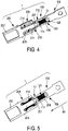
FIG. 4 ] is a schematic longitudinal cross-section of the male and female terminal assembly illustrated inFIG. 1 ; - [
FIG.5 ] is a schematic longitudinal cross-section of a male and female terminal assembly according to a second embodiment; - [
FIG. 6 ] is a schematic longitudinal cross-section of a female terminal configured for being used in the male and female terminal assembly illustrated inFIG. 5 ; - [
FIG. 7 ] is a schematic longitudinal cross-section of an example of male and female terminal assembly according to the prior art. - Two examples of examples of embodiments of male and
female terminal assemblies 1 are described below. - According to these two examples, the male and
female terminal assemblies 1 comprise amale terminal 100 extending longitudinally in a back-to-front direction BF. The back-to-front direction BF is parallel to a mating direction, i.e. a direction along which themale terminal 100 is inserted in afemale terminal 200 during the mating operation of the male and female connectors, respectively the male 100 and female 200 terminals. The male and female connectors comprise respectively a male connector housing 1000 and a female connector housing 2000, as illustrated inFigure 7 . The male andfemale connector housings female connector housings FIG. 7 for a prior art connector assembly (the housings of the present disclosure are identical or similar to the housings of the prior art connectors), at least onecavity 100A, respectively 200A, accommodating a male 100 or a female 200 power terminal. Eachcavity aperture 100B, respectively 200B, made in the respective mating face of the male or female connector housing 1000, 2000. Eachaperture appropriate protection elements - As illustrated in
FIG. 2 , themale terminal 100 comprises amale connection portion 102 and amale contact portion 103. Themale connection portion 102 and themale contact portion 103 are integrally formed with each other. In other words, themale connection portion 102 and themale contact portion 103 form a single-piece part. Themale connection portion 102 and themale contact portion 102 are made of an electrically conductive material, such as a copper alloy. Themale connection portion 102 is configured for electrically connecting, by crimping, soldering, bolting, etc. themale terminal 100 to an electrical cable, a busbar or any other appropriate equipment. Themale contact portion 103 comprises a cylindricalsolid portion 104 and a cylindricalhollow portion 105. The cylindricalhollow portion 105 extends in the back-to-front direction BF between the cylindricalsolid portion 104 and afront end 106. Thefront end 106 is provided with anopening 107 andfitting features 108 configured to mount aprotection element 101. For example, theprotection element 101 has an essentially annular shape arranged in front and around theopening 107. The gap between the male connector housing 1000 and theprotection element 101 is such that the "finger touch" prevention function is ensured. - For a
male power terminal 100 having a diameter of 14 millimetres, thewall 109 of the cylindricalhollow portion 105 has for example a thickness T of about 2.5 millimetres. Such a thickness T is sufficient for carrying high intensity current at least up to 600 Amps. The cylindricalhollow portion 105 has anouter contact surface 110 and aninner surface 111. A connectingmember 120, made of an electrically conductive material, is placed inside the cylindricalhollow portion 105 of themale terminal 100. The connectingmember 120 placed inside the cylindricalhollow portion 105 comprises a plurality ofresilient strips 121 each extending essentially longitudinally between tworings 122. Eachring 122 is in electrical contact with theinner surface 111 of the cylindricalhollow portion 105. Eachstrip 121 is bent so as to be able to resiliently be pushed toward theinner surface 111 and to exert a contact force at at least one contact point. - As illustrated in
FIG. 3 , according to the first embodiment, thefemale terminal 200 extends longitudinally parallel to, and in the reverse direction to, the back-to-front direction BF, from afemale connection portion 202 to afemale contact portion 203. Thefemale connection portion 202 and thefemale contact portion 203 are integrally formed with each other. In other words, thefemale connection portion 202 and thefemale contact portion 203 form a single-piece part. Thefemale connection portion 202 and thefemale contact portion 203 are made of an electrically conductive material, such as a copper alloy. In the embodiment, illustrated inFIG. 3 , thefemale connection portion 202 is configured for electrically connecting, by crimping and/or soldering, thefemale terminal 200 to an electrical cable. According to variations, thefemale connection portion 202 is configured to connect to a busbar or any other appropriate equipment. - The
female contact portion 203 comprises asleeve 204 and afinger 205. Thesleeve 204 and thefinger 205 are integrally formed with each other. In other words, thesleeve 204 and thefinger 205 form a single-piece part. Thesleeve 204 and thefinger 205 are made of an electrically conductive material. Thesleeve 204 is configured so to receive themale contact portion 103 when the male and female connectors are mated. Thesleeve 204 extends, in the reverse direction to the back-to-front direction BF, up to anannular opening 207. Theannular opening 207 extends in a plane perpendicular to the back-to-front direction BF. Thesleeve 204 comprises a plurality ofresilient blades 206 extending longitudinally, parallel to the back-to-front direction BF, up this plane. Thefinger 205 comprises aconductive portion 208 made of an electrically conductive material. Theconductive portion 208 extends in the reverse direction to the back-to-front direction BF essentially up this plane too. Theprotection element 201 is attached to theconductive portion 208 by overmolding, or by insertion of a portion of theprotection element 201 into theconductive portion 208, or by insertion of a portion of theconductive portion 208 into theprotection element 201, etc. Theprotection element 201 is made of an electrically insulating material, and attached at the free end of thefinger 205. Theprotection element 201 sticks out further from theannular opening 207 formed by the free end of theblades 206. In other words, theprotection element 201 is placed essentially on the other side of the plane with regard to the free end of theblades 206. The gap between thefemale connector housing 2000 and theprotection element 201 is such that the "finger touch" prevention function is ensured. - Each
blade 206 is provided with at least one contact point. In the vicinity of thefemale connection portion 202, eachblade 206 is provided with anarrow portion 210 in order to make theblade 206 more flexible. In the vicinity of its free end, on itsinner surface 211, eachblade 206 is provided with abulge 209 extending from theinner surface 211 of eachblade 206 toward thefinger 205. In the vicinity of its free end, on itsouter surface 212, eachblade 206 is provided with anotch 213 configured to accommodate a spring ring (not shown) that both strengthens thefemale contact portion 203 and increases the contact force at the contact point located on eachbulge 209. - When the male and female connectors are mated, the
male contact portion 103 is inserted in thefemale contact portion 203. More particularly, theouter contact surface 110 of themale contact portion 103 faces (at least over a certain area) theinner surface 211 of theblades 206, and thebulges 209 make an electrical contact with theouter contact surface 110 of themale contact portion 103. Further, theinner surface 111 of thewall 109 of the cylindricalhollow portion 105 faces (at least over a certain area) theouter surface 214 of thefinger 205, and the bent portion of theresilient strips 121 makes an electrical contact with theouter surface 214 of thefinger 205. Therefore, between the male 100 and female 200 terminals, there are contact points between eachblade 206 of thefemale terminal 200 and themale contact portion 103, but also between thefinger 205 and theinner surface 111 of themale contact portion 103 through the connecting member120 (seeFIG. 4 ). Such a configuration allows for a conduction of higher current intensities through the male 100 and female 200 terminals without excessive heating. - As illustrated in
FIGs. 5 and6 , according to the second embodiment, thefemale terminal 200 differs from the first embodiment essentially by thesleeve 204 of itsfemale contact portion 203. Thefemale connection portion 202, thefinger 205 and theprotection element 201 are similar or the same as those already disclosed in connection with the first embodiment. They will not be described again. - The
sleeve 204 and thefinger 205 are integrally formed with each other. In other words, thesleeve 204 and thefinger 205 form a single-piece part. Thesleeve 204 and thefinger 205 are made of an electrically conductive material. Thesleeve 204 is configured so to receive themale contact portion 103 when the male and female connectors are mated. Thesleeve 204 extends in the reverse direction to the back-to-front direction BF up to anannular opening 207. Theannular opening 207 extends in a plane perpendicular to the back-to-front BF direction. Thesleeve 204 comprises acylindrical wall 215 with anannular rib 216 around theannular opening 207. Therib 216 extends toward thefinger 205, so as to maintain a connectingmember 220 placed in saidsleeve 204. The movement of the connectingmember 220 parallel to the back-to-front direction BF is blocked in one direction by therib 216 and in the opposite direction by aledge 217 located at the bottom of thesleeve 204. The connectingmember 220 comprises a plurality ofresilient strips 221 extending between tworings 222 stopped respectively by theledge 217 and therib 216. Eachring 222 is in electrical contact with theinner surface 211 of thecylindrical wall 215 of thefemale contact portion 203. Eachstrip 221 is bent toward thefinger 205 so as to form a contact zone or contact point configured for electrically contacting theouter contact surface 110 of themale power terminal 100, when the male and female connectors are mated. - When the male 1000 and female 2000 connectors are mated, the
male contact portion 103 is inserted in thefemale contact portion 203. More particularly, theouter contact surface 110 of themale contact portion 103 faces (at least over a certain area) theinner surface 211 of thecylindrical wall 215 of thefemale contact portion 203, and the bent portion of eachstrip 221 of thefemale terminal 200 makes an electrical contact with theouter contact surface 110 of themale contact portion 103. Further, theinner surface 111 of thewall 109 of the cylindricalhollow portion 105 faces (at least over a certain area) theouter surface 214 of thefinger 205, and the bent portion of theresilient strips 121 of themale terminal 100 makes an electrical contact with theouter surface 214 of thefinger 205. Therefore, between the male 100 and female 200 terminals, there are contact points between eachstrip 221 of the connectingmember 220 mounted in thefemale terminal 200 and themale contact portion 103 of themale terminal 100, but also between thefinger 205 and theinner surface 111 of themale contact portion 103 through the connectingmember 120 of themale terminal 100. Such a configuration allows for a conduction of higher current intensities through the male 100 and female 200 terminals without excessive heating.
Claims (14)
- Male and female power terminal assembly (1), comprising
a male terminal (100) extending longitudinally in a back-to-front direction (BF), from a male connection portion (102) to a male contact portion (103), the male contact portion (103) comprising a cylindrical hollow portion (105) made of an electrically conductive material, with an outer contact surface (110) and an inner surface (111),
a female terminal (200) extending longitudinally parallel to, and in the reverse direction to, the back-to-front direction (BF), from a female connection portion (202) to a female contact portion (203), the female contact portion (203) comprising- a sleeve (204) made of an electrically conductive material, within which the male contact portion (103) is accommodated, and- a finger (205) extending inside the sleeve (204) parallel to, and in the reverse direction to, the back-to-front direction (BF) from a base attached to the sleeve (204) to a free end,wherein said outer contact surface (110) of said male terminal (100) is electrically connected to an inner surface (211) of said sleeve (204),
characterized in that said finger (205) comprises a conductive portion (208) made of an electrically conductive material and in that the male terminal (100) further comprises a connecting member (120) made of an electrically conductive material, which is placed inside the cylindrical hollow portion (105) of the male terminal (100) and which interconnects said conductive portion (208) with said inner surface (111) of said cylindrical hollow portion (105). - The assembly (1) of claim 1, wherein said finger (205) comprises a protection element (201), made of an electrically insulating material, and attached at said free end of the finger (205).
- The assembly (1) of claim 1 or 2, wherein said sleeve (204) extends in the reverse direction to the back-to-front direction (BF) up to an opening (207) extending in a plane perpendicular to the back-to-front direction (BF) and said conductive portion (208) extends in the reverse direction to the back-to-front direction (BF) up said plane.
- The assembly (1) according to claim 3, wherein the sleeve (204) comprises a plurality of resilient blades (206) extending longitudinally parallel to the back-to-front direction (BF) up said plane, and having at least one contact point electrically contacting said outer contact surface (110).
- The assembly (1) according to any one of claims 1 to 3, comprising a connecting member (220) placed in said sleeve (204) and comprising a plurality of resilient strips (221), each strip (221) having at least one contact point electrically contacting said outer contact surface (110).
- Female power terminal (200) extending parallel to a longitudinal direction, from a female connection portion (202) to a female contact portion (203), the female contact portion (203) comprising- a sleeve (204) made of an electrically conductive material, said sleeve (204) extending up to an opening (207) extending in a plane perpendicular to the longitudinal direction, and- a finger (205) extending inside the sleeve (204), parallel to a longitudinal direction, from a base attached to the sleeve (204) to a free end,characterized in that said finger (205) comprises a conductive portion (208) made of an electrically conductive material.
- The female power terminal (200) of claim 6, wherein said conductive portion (208) extends parallel to the longitudinal direction up to said plane.
- The female power terminal (200) of claim 7, wherein said finger (205) comprises a protection element (201), made of an electrically insulating material, and attached at said free end of the finger (205) so as to stick out further from said opening (207).
- The female power terminal (200) according to any one of claims 6 to 8, wherein the sleeve (204) comprises a plurality of resilient blades (206) extending longitudinally up said plane, each blade (206) having at least one contact point configured for electrically contacting the outer contact surface (110) of a male terminal (100).
- The female power terminal (200) according to any one of claims 6 to 8, comprising a connecting member (220) placed in said sleeve (204) and comprising a plurality of resilient strips (221), each strip (221) having at least one contact point configured for electrically contacting the outer contact surface (110) of a male terminal (100).
- Male power terminal (100) for cooperation with a female terminal according to one of claims 6 to 10, extending longitudinally in a back-to-front direction (BF), from a male connection portion (102) to a male contact portion (103), the male contact portion (103) comprising a cylindrical hollow portion (104) made of an electrically conductive material, having an outer contact surface (110) configured to be in electrical contact with said female terminal (200) and having an inner surface (111), characterized in that it further comprises a connecting member (120) made of an electrically conductive material, which is placed inside the cylindrical hollow portion (105) and which is configured to be in electrical contact with said female terminal (200).
- The male power terminal (100) according to claim 11, wherein the cylindrical hollow portion (105) is formed as an essentially tubular wall (109) having a radial thickness (T) equal or greater than 2.5 millimetres.
- Male power connector comprising at least one male power terminal (100) according to claim 11 or 12, the male connector comprising a male connector housing (1000) made of electrically insulating material and comprising at least one cavity (100A) for housing at least one male power terminal (100) , said at least one cavity (100A) opening into an aperture (100B) configured for providing a "finger touch" prevention function, with a protection element (101) mounted on said at least one male power terminal (100).
- Female power connector comprising at least one female power terminal (200) according to claim 6 to 10, the female connector comprising a female connector housing (2000) made of electrically insulating material and comprising at least one cavity (200A) for housing at least one female power terminal (200), said at least one cavity (200A) opening into an aperture (200B) configured for providing a "finger touch" prevention function, with a protection element (201) mounted on said at least one female power terminal (200).
Priority Applications (3)
| Application Number | Priority Date | Filing Date | Title |
|---|---|---|---|
| EP21177265.2A EP4099519B1 (en) | 2021-06-01 | 2021-06-01 | Male and female power terminal assembly, female and male power terminals |
| US17/828,381 US12633695B2 (en) | 2021-06-01 | 2022-05-31 | Male and female power terminal assembly, female and male power terminals |
| CN202210615402.7A CN115441227A (en) | 2021-06-01 | 2022-06-01 | Male and female power terminal assembly, female power terminal and male power terminal |
Applications Claiming Priority (1)
| Application Number | Priority Date | Filing Date | Title |
|---|---|---|---|
| EP21177265.2A EP4099519B1 (en) | 2021-06-01 | 2021-06-01 | Male and female power terminal assembly, female and male power terminals |
Publications (2)
| Publication Number | Publication Date |
|---|---|
| EP4099519A1 true EP4099519A1 (en) | 2022-12-07 |
| EP4099519B1 EP4099519B1 (en) | 2024-10-30 |
Family
ID=76250136
Family Applications (1)
| Application Number | Title | Priority Date | Filing Date |
|---|---|---|---|
| EP21177265.2A Active EP4099519B1 (en) | 2021-06-01 | 2021-06-01 | Male and female power terminal assembly, female and male power terminals |
Country Status (2)
| Country | Link |
|---|---|
| EP (1) | EP4099519B1 (en) |
| CN (1) | CN115441227A (en) |
Cited By (1)
| Publication number | Priority date | Publication date | Assignee | Title |
|---|---|---|---|---|
| EP4478548A1 (en) | 2023-06-12 | 2024-12-18 | Aptiv Technologies AG | Contact terminal for a connector and method of producing the same |
Families Citing this family (1)
| Publication number | Priority date | Publication date | Assignee | Title |
|---|---|---|---|---|
| CN116154509A (en) * | 2023-01-03 | 2023-05-23 | 康联精密机电(深圳)有限公司 | Connector |
Citations (4)
| Publication number | Priority date | Publication date | Assignee | Title |
|---|---|---|---|---|
| US20090318009A1 (en) * | 2008-06-20 | 2009-12-24 | Delphi Technologies, Inc. | Connector retainer |
| US10553996B2 (en) | 2018-05-14 | 2020-02-04 | Yazaki Corporation | Female connector and fitting connector |
| EP3641068A1 (en) * | 2018-10-16 | 2020-04-22 | ODU GmbH & Co KG. | Connecting plug and socket with lamella basket |
| WO2020099881A1 (en) * | 2018-11-16 | 2020-05-22 | Zodiac Interconnect Uk Limited | An electrical connector |
Family Cites Families (4)
| Publication number | Priority date | Publication date | Assignee | Title |
|---|---|---|---|---|
| GB2461346B (en) * | 2008-07-04 | 2013-02-13 | Smiths Group Plc | Electrical connectors |
| US8246392B2 (en) * | 2009-09-09 | 2012-08-21 | John Mezzalingua Associates, Inc. | Securable connector |
| CN203800335U (en) * | 2014-04-10 | 2014-08-27 | 东莞中探探针有限公司 | Electrical connector |
| DE102020112117A1 (en) * | 2020-05-05 | 2021-11-11 | Te Connectivity Germany Gmbh | Connector, connector counterpart and connector system |
-
2021
- 2021-06-01 EP EP21177265.2A patent/EP4099519B1/en active Active
-
2022
- 2022-06-01 CN CN202210615402.7A patent/CN115441227A/en active Pending
Patent Citations (4)
| Publication number | Priority date | Publication date | Assignee | Title |
|---|---|---|---|---|
| US20090318009A1 (en) * | 2008-06-20 | 2009-12-24 | Delphi Technologies, Inc. | Connector retainer |
| US10553996B2 (en) | 2018-05-14 | 2020-02-04 | Yazaki Corporation | Female connector and fitting connector |
| EP3641068A1 (en) * | 2018-10-16 | 2020-04-22 | ODU GmbH & Co KG. | Connecting plug and socket with lamella basket |
| WO2020099881A1 (en) * | 2018-11-16 | 2020-05-22 | Zodiac Interconnect Uk Limited | An electrical connector |
Cited By (1)
| Publication number | Priority date | Publication date | Assignee | Title |
|---|---|---|---|---|
| EP4478548A1 (en) | 2023-06-12 | 2024-12-18 | Aptiv Technologies AG | Contact terminal for a connector and method of producing the same |
Also Published As
| Publication number | Publication date |
|---|---|
| EP4099519B1 (en) | 2024-10-30 |
| CN115441227A (en) | 2022-12-06 |
| US20220384973A1 (en) | 2022-12-01 |
Similar Documents
| Publication | Publication Date | Title |
|---|---|---|
| CN108475889B (en) | High-power electric connector | |
| EP3584889B1 (en) | Connector device | |
| US9653859B1 (en) | Electrical connector system | |
| US4280749A (en) | Socket and pin contacts for coaxial cable | |
| CN104124574B (en) | There is the cable assembly forcing to keep lock-in feature | |
| JP2018026323A (en) | Radio frequency coaxial connector assembly and method of manufacturing the assembly | |
| EP2141775A2 (en) | Electrical connectors | |
| US5135417A (en) | Dual usage electrical/electronic pin terminal system | |
| EP4099519B1 (en) | Male and female power terminal assembly, female and male power terminals | |
| US10916873B2 (en) | Connection assembly, female contact, and connection method thereof | |
| EP0952631A2 (en) | Male contact | |
| EP4167398A1 (en) | Electrical plug connector for a busbar, mating connector and method for assembling a busbar | |
| US11296449B2 (en) | Electrical connector assembly having identical electrical connectors | |
| EP2856572A1 (en) | Interconnection assembly for vehicle devices and method of interconnection | |
| US20070059973A1 (en) | Hot plug wire contact and connector assembly | |
| EP4274033A1 (en) | Electrical power connector assembly | |
| EP0568927A1 (en) | Electrical socket terminal | |
| CN211404810U (en) | High-voltage interlocking mechanism for high-voltage connector | |
| US12633695B2 (en) | Male and female power terminal assembly, female and male power terminals | |
| CN112290265A (en) | Female power contact | |
| US20250279593A1 (en) | Electric cable or electric wire provided with a plug contour for directly plugging into a mating plug | |
| CN121153173A (en) | Fitting element for a connector | |
| JP7787246B2 (en) | Plug connectors, plug connector mating parts, and plug connector systems | |
| EP4262028A1 (en) | Electric connector assembly for a high-voltage terminal and method for assembling | |
| EP4439870A1 (en) | Female contact with at least one new wire assembly |
Legal Events
| Date | Code | Title | Description |
|---|---|---|---|
| PUAI | Public reference made under article 153(3) epc to a published international application that has entered the european phase |
Free format text: ORIGINAL CODE: 0009012 |
|
| STAA | Information on the status of an ep patent application or granted ep patent |
Free format text: STATUS: THE APPLICATION HAS BEEN PUBLISHED |
|
| AK | Designated contracting states |
Kind code of ref document: A1 Designated state(s): AL AT BE BG CH CY CZ DE DK EE ES FI FR GB GR HR HU IE IS IT LI LT LU LV MC MK MT NL NO PL PT RO RS SE SI SK SM TR |
|
| RAP3 | Party data changed (applicant data changed or rights of an application transferred) |
Owner name: APTIV TECHNOLOGIES LIMITED |
|
| STAA | Information on the status of an ep patent application or granted ep patent |
Free format text: STATUS: REQUEST FOR EXAMINATION WAS MADE |
|
| 17P | Request for examination filed |
Effective date: 20230328 |
|
| RBV | Designated contracting states (corrected) |
Designated state(s): AL AT BE BG CH CY CZ DE DK EE ES FI FR GB GR HR HU IE IS IT LI LT LU LV MC MK MT NL NO PL PT RO RS SE SI SK SM TR |
|
| GRAP | Despatch of communication of intention to grant a patent |
Free format text: ORIGINAL CODE: EPIDOSNIGR1 |
|
| STAA | Information on the status of an ep patent application or granted ep patent |
Free format text: STATUS: GRANT OF PATENT IS INTENDED |
|
| RIC1 | Information provided on ipc code assigned before grant |
Ipc: H01R 13/08 20060101ALI20240621BHEP Ipc: H01R 13/11 20060101ALI20240621BHEP Ipc: H01R 13/187 20060101ALI20240621BHEP Ipc: H01R 13/44 20060101ALI20240621BHEP Ipc: H01R 101/00 20060101ALI20240621BHEP Ipc: H01R 24/84 20110101AFI20240621BHEP |
|
| INTG | Intention to grant announced |
Effective date: 20240716 |
|
| GRAS | Grant fee paid |
Free format text: ORIGINAL CODE: EPIDOSNIGR3 |
|
| GRAA | (expected) grant |
Free format text: ORIGINAL CODE: 0009210 |
|
| STAA | Information on the status of an ep patent application or granted ep patent |
Free format text: STATUS: THE PATENT HAS BEEN GRANTED |
|
| P01 | Opt-out of the competence of the unified patent court (upc) registered |
Free format text: CASE NUMBER: APP_49774/2024 Effective date: 20240902 |
|
| RAP1 | Party data changed (applicant data changed or rights of an application transferred) |
Owner name: APTIV TECHNOLOGIES AG |
|
| AK | Designated contracting states |
Kind code of ref document: B1 Designated state(s): AL AT BE BG CH CY CZ DE DK EE ES FI FR GB GR HR HU IE IS IT LI LT LU LV MC MK MT NL NO PL PT RO RS SE SI SK SM TR |
|
| RAP3 | Party data changed (applicant data changed or rights of an application transferred) |
Owner name: APTIV TECHNOLOGIES AG |
|
| REG | Reference to a national code |
Ref country code: GB Ref legal event code: FG4D |
|
| REG | Reference to a national code |
Ref country code: CH Ref legal event code: EP |
|
| REG | Reference to a national code |
Ref country code: DE Ref legal event code: R096 Ref document number: 602021020873 Country of ref document: DE |
|
| REG | Reference to a national code |
Ref country code: IE Ref legal event code: FG4D |
|
| REG | Reference to a national code |
Ref country code: LT Ref legal event code: MG9D |
|
| REG | Reference to a national code |
Ref country code: NL Ref legal event code: MP Effective date: 20241030 |
|
| PG25 | Lapsed in a contracting state [announced via postgrant information from national office to epo] |
Ref country code: IS Free format text: LAPSE BECAUSE OF FAILURE TO SUBMIT A TRANSLATION OF THE DESCRIPTION OR TO PAY THE FEE WITHIN THE PRESCRIBED TIME-LIMIT Effective date: 20250228 Ref country code: HR Free format text: LAPSE BECAUSE OF FAILURE TO SUBMIT A TRANSLATION OF THE DESCRIPTION OR TO PAY THE FEE WITHIN THE PRESCRIBED TIME-LIMIT Effective date: 20241030 Ref country code: PT Free format text: LAPSE BECAUSE OF FAILURE TO SUBMIT A TRANSLATION OF THE DESCRIPTION OR TO PAY THE FEE WITHIN THE PRESCRIBED TIME-LIMIT Effective date: 20250228 |
|
| PG25 | Lapsed in a contracting state [announced via postgrant information from national office to epo] |
Ref country code: NL Free format text: LAPSE BECAUSE OF FAILURE TO SUBMIT A TRANSLATION OF THE DESCRIPTION OR TO PAY THE FEE WITHIN THE PRESCRIBED TIME-LIMIT Effective date: 20241030 Ref country code: FI Free format text: LAPSE BECAUSE OF FAILURE TO SUBMIT A TRANSLATION OF THE DESCRIPTION OR TO PAY THE FEE WITHIN THE PRESCRIBED TIME-LIMIT Effective date: 20241030 |
|
| REG | Reference to a national code |
Ref country code: AT Ref legal event code: MK05 Ref document number: 1737872 Country of ref document: AT Kind code of ref document: T Effective date: 20241030 |
|
| PG25 | Lapsed in a contracting state [announced via postgrant information from national office to epo] |
Ref country code: BG Free format text: LAPSE BECAUSE OF FAILURE TO SUBMIT A TRANSLATION OF THE DESCRIPTION OR TO PAY THE FEE WITHIN THE PRESCRIBED TIME-LIMIT Effective date: 20241030 |
|
| PG25 | Lapsed in a contracting state [announced via postgrant information from national office to epo] |
Ref country code: ES Free format text: LAPSE BECAUSE OF FAILURE TO SUBMIT A TRANSLATION OF THE DESCRIPTION OR TO PAY THE FEE WITHIN THE PRESCRIBED TIME-LIMIT Effective date: 20241030 |
|
| PG25 | Lapsed in a contracting state [announced via postgrant information from national office to epo] |
Ref country code: NO Free format text: LAPSE BECAUSE OF FAILURE TO SUBMIT A TRANSLATION OF THE DESCRIPTION OR TO PAY THE FEE WITHIN THE PRESCRIBED TIME-LIMIT Effective date: 20250130 |
|
| PG25 | Lapsed in a contracting state [announced via postgrant information from national office to epo] |
Ref country code: LV Free format text: LAPSE BECAUSE OF FAILURE TO SUBMIT A TRANSLATION OF THE DESCRIPTION OR TO PAY THE FEE WITHIN THE PRESCRIBED TIME-LIMIT Effective date: 20241030 Ref country code: GR Free format text: LAPSE BECAUSE OF FAILURE TO SUBMIT A TRANSLATION OF THE DESCRIPTION OR TO PAY THE FEE WITHIN THE PRESCRIBED TIME-LIMIT Effective date: 20250131 Ref country code: AT Free format text: LAPSE BECAUSE OF FAILURE TO SUBMIT A TRANSLATION OF THE DESCRIPTION OR TO PAY THE FEE WITHIN THE PRESCRIBED TIME-LIMIT Effective date: 20241030 |
|
| PG25 | Lapsed in a contracting state [announced via postgrant information from national office to epo] |
Ref country code: PL Free format text: LAPSE BECAUSE OF FAILURE TO SUBMIT A TRANSLATION OF THE DESCRIPTION OR TO PAY THE FEE WITHIN THE PRESCRIBED TIME-LIMIT Effective date: 20241030 |
|
| PG25 | Lapsed in a contracting state [announced via postgrant information from national office to epo] |
Ref country code: RS Free format text: LAPSE BECAUSE OF FAILURE TO SUBMIT A TRANSLATION OF THE DESCRIPTION OR TO PAY THE FEE WITHIN THE PRESCRIBED TIME-LIMIT Effective date: 20250130 |
|
| PG25 | Lapsed in a contracting state [announced via postgrant information from national office to epo] |
Ref country code: SM Free format text: LAPSE BECAUSE OF FAILURE TO SUBMIT A TRANSLATION OF THE DESCRIPTION OR TO PAY THE FEE WITHIN THE PRESCRIBED TIME-LIMIT Effective date: 20241030 |
|
| PGFP | Annual fee paid to national office [announced via postgrant information from national office to epo] |
Ref country code: DE Payment date: 20250519 Year of fee payment: 5 |
|
| PG25 | Lapsed in a contracting state [announced via postgrant information from national office to epo] |
Ref country code: DK Free format text: LAPSE BECAUSE OF FAILURE TO SUBMIT A TRANSLATION OF THE DESCRIPTION OR TO PAY THE FEE WITHIN THE PRESCRIBED TIME-LIMIT Effective date: 20241030 |
|
| PGFP | Annual fee paid to national office [announced via postgrant information from national office to epo] |
Ref country code: GB Payment date: 20250512 Year of fee payment: 5 |
|
| PG25 | Lapsed in a contracting state [announced via postgrant information from national office to epo] |
Ref country code: EE Free format text: LAPSE BECAUSE OF FAILURE TO SUBMIT A TRANSLATION OF THE DESCRIPTION OR TO PAY THE FEE WITHIN THE PRESCRIBED TIME-LIMIT Effective date: 20241030 |
|
| PGFP | Annual fee paid to national office [announced via postgrant information from national office to epo] |
Ref country code: FR Payment date: 20250513 Year of fee payment: 5 |
|
| PG25 | Lapsed in a contracting state [announced via postgrant information from national office to epo] |
Ref country code: RO Free format text: LAPSE BECAUSE OF FAILURE TO SUBMIT A TRANSLATION OF THE DESCRIPTION OR TO PAY THE FEE WITHIN THE PRESCRIBED TIME-LIMIT Effective date: 20241030 |
|
| PG25 | Lapsed in a contracting state [announced via postgrant information from national office to epo] |
Ref country code: SK Free format text: LAPSE BECAUSE OF FAILURE TO SUBMIT A TRANSLATION OF THE DESCRIPTION OR TO PAY THE FEE WITHIN THE PRESCRIBED TIME-LIMIT Effective date: 20241030 |
|
| PG25 | Lapsed in a contracting state [announced via postgrant information from national office to epo] |
Ref country code: CZ Free format text: LAPSE BECAUSE OF FAILURE TO SUBMIT A TRANSLATION OF THE DESCRIPTION OR TO PAY THE FEE WITHIN THE PRESCRIBED TIME-LIMIT Effective date: 20241030 |
|
| PG25 | Lapsed in a contracting state [announced via postgrant information from national office to epo] |
Ref country code: IT Free format text: LAPSE BECAUSE OF FAILURE TO SUBMIT A TRANSLATION OF THE DESCRIPTION OR TO PAY THE FEE WITHIN THE PRESCRIBED TIME-LIMIT Effective date: 20241030 |
|
| REG | Reference to a national code |
Ref country code: DE Ref legal event code: R097 Ref document number: 602021020873 Country of ref document: DE |
|
| PLBE | No opposition filed within time limit |
Free format text: ORIGINAL CODE: 0009261 |
|
| STAA | Information on the status of an ep patent application or granted ep patent |
Free format text: STATUS: NO OPPOSITION FILED WITHIN TIME LIMIT |
|
| PG25 | Lapsed in a contracting state [announced via postgrant information from national office to epo] |
Ref country code: SE Free format text: LAPSE BECAUSE OF FAILURE TO SUBMIT A TRANSLATION OF THE DESCRIPTION OR TO PAY THE FEE WITHIN THE PRESCRIBED TIME-LIMIT Effective date: 20241030 |
|
| 26N | No opposition filed |
Effective date: 20250731 |
|
| REG | Reference to a national code |
Ref country code: CH Ref legal event code: H13 Free format text: ST27 STATUS EVENT CODE: U-0-0-H10-H13 (AS PROVIDED BY THE NATIONAL OFFICE) Effective date: 20260127 |
|
| PG25 | Lapsed in a contracting state [announced via postgrant information from national office to epo] |
Ref country code: MC Free format text: LAPSE BECAUSE OF FAILURE TO SUBMIT A TRANSLATION OF THE DESCRIPTION OR TO PAY THE FEE WITHIN THE PRESCRIBED TIME-LIMIT Effective date: 20241030 |
|
| PG25 | Lapsed in a contracting state [announced via postgrant information from national office to epo] |
Ref country code: LU Free format text: LAPSE BECAUSE OF NON-PAYMENT OF DUE FEES Effective date: 20250601 |
|
| REG | Reference to a national code |
Ref country code: BE Ref legal event code: MM Effective date: 20250630 |
|
| PG25 | Lapsed in a contracting state [announced via postgrant information from national office to epo] |
Ref country code: IE Free format text: LAPSE BECAUSE OF NON-PAYMENT OF DUE FEES Effective date: 20250601 |
|
| PG25 | Lapsed in a contracting state [announced via postgrant information from national office to epo] |
Ref country code: BE Free format text: LAPSE BECAUSE OF NON-PAYMENT OF DUE FEES Effective date: 20250630 |
|
| PG25 | Lapsed in a contracting state [announced via postgrant information from national office to epo] |
Ref country code: CH Free format text: LAPSE BECAUSE OF NON-PAYMENT OF DUE FEES Effective date: 20250630 |