EP3641068A1 - Connecting plug and socket with lamella basket - Google Patents
Connecting plug and socket with lamella basket Download PDFInfo
- Publication number
- EP3641068A1 EP3641068A1 EP18200774.0A EP18200774A EP3641068A1 EP 3641068 A1 EP3641068 A1 EP 3641068A1 EP 18200774 A EP18200774 A EP 18200774A EP 3641068 A1 EP3641068 A1 EP 3641068A1
- Authority
- EP
- European Patent Office
- Prior art keywords
- lamellae
- socket
- annular
- lamella basket
- lamella
- Prior art date
- Legal status (The legal status is an assumption and is not a legal conclusion. Google has not performed a legal analysis and makes no representation as to the accuracy of the status listed.)
- Granted
Links
- 241000446313 Lamella Species 0.000 title claims abstract description 201
- 238000003466 welding Methods 0.000 claims description 19
- 238000004049 embossing Methods 0.000 claims description 6
- 238000000034 method Methods 0.000 claims description 6
- 239000012777 electrically insulating material Substances 0.000 claims description 5
- 238000003825 pressing Methods 0.000 claims description 5
- 230000013011 mating Effects 0.000 description 44
- 229910052751 metal Inorganic materials 0.000 description 20
- 239000002184 metal Substances 0.000 description 20
- 229910000881 Cu alloy Inorganic materials 0.000 description 14
- 229910045601 alloy Inorganic materials 0.000 description 14
- 239000000956 alloy Substances 0.000 description 14
- 239000000463 material Substances 0.000 description 13
- RYGMFSIKBFXOCR-UHFFFAOYSA-N Copper Chemical compound [Cu] RYGMFSIKBFXOCR-UHFFFAOYSA-N 0.000 description 12
- 239000010949 copper Substances 0.000 description 12
- 229910052802 copper Inorganic materials 0.000 description 10
- 239000004020 conductor Substances 0.000 description 9
- 238000007373 indentation Methods 0.000 description 8
- 238000003780 insertion Methods 0.000 description 6
- 230000037431 insertion Effects 0.000 description 6
- 238000004519 manufacturing process Methods 0.000 description 6
- 239000004033 plastic Substances 0.000 description 6
- 230000006378 damage Effects 0.000 description 5
- 238000007747 plating Methods 0.000 description 5
- 229910001220 stainless steel Inorganic materials 0.000 description 5
- 239000010935 stainless steel Substances 0.000 description 5
- 229910000570 Cupronickel Inorganic materials 0.000 description 4
- GXDVEXJTVGRLNW-UHFFFAOYSA-N [Cr].[Cu] Chemical compound [Cr].[Cu] GXDVEXJTVGRLNW-UHFFFAOYSA-N 0.000 description 4
- YOCUPQPZWBBYIX-UHFFFAOYSA-N copper nickel Chemical compound [Ni].[Cu] YOCUPQPZWBBYIX-UHFFFAOYSA-N 0.000 description 4
- 230000002829 reductive effect Effects 0.000 description 4
- 244000043261 Hevea brasiliensis Species 0.000 description 3
- BQCADISMDOOEFD-UHFFFAOYSA-N Silver Chemical compound [Ag] BQCADISMDOOEFD-UHFFFAOYSA-N 0.000 description 3
- 229910000831 Steel Inorganic materials 0.000 description 3
- 229920001971 elastomer Polymers 0.000 description 3
- 239000000806 elastomer Substances 0.000 description 3
- PCHJSUWPFVWCPO-UHFFFAOYSA-N gold Chemical compound [Au] PCHJSUWPFVWCPO-UHFFFAOYSA-N 0.000 description 3
- 229910052737 gold Inorganic materials 0.000 description 3
- 239000010931 gold Substances 0.000 description 3
- 239000011810 insulating material Substances 0.000 description 3
- 229920003052 natural elastomer Polymers 0.000 description 3
- 229920001194 natural rubber Polymers 0.000 description 3
- 239000002861 polymer material Substances 0.000 description 3
- 229910052709 silver Inorganic materials 0.000 description 3
- 239000004332 silver Substances 0.000 description 3
- 239000010959 steel Substances 0.000 description 3
- 229920003051 synthetic elastomer Polymers 0.000 description 3
- 239000005061 synthetic rubber Substances 0.000 description 3
- 229910001369 Brass Inorganic materials 0.000 description 2
- 238000005452 bending Methods 0.000 description 2
- 239000010951 brass Substances 0.000 description 2
- 230000000295 complement effect Effects 0.000 description 2
- 238000010276 construction Methods 0.000 description 2
- 238000001125 extrusion Methods 0.000 description 2
- 238000005304 joining Methods 0.000 description 2
- 230000000717 retained effect Effects 0.000 description 2
- QZCHKAUWIRYEGK-UHFFFAOYSA-N tellanylidenecopper Chemical compound [Te]=[Cu] QZCHKAUWIRYEGK-UHFFFAOYSA-N 0.000 description 2
- 229910000952 Be alloy Inorganic materials 0.000 description 1
- 229910001339 C alloy Inorganic materials 0.000 description 1
- 229910001128 Sn alloy Inorganic materials 0.000 description 1
- 230000003190 augmentative effect Effects 0.000 description 1
- 230000001010 compromised effect Effects 0.000 description 1
- 230000007423 decrease Effects 0.000 description 1
- 230000003247 decreasing effect Effects 0.000 description 1
- 230000001419 dependent effect Effects 0.000 description 1
- 230000007613 environmental effect Effects 0.000 description 1
- 238000002347 injection Methods 0.000 description 1
- 239000007924 injection Substances 0.000 description 1
- 238000001746 injection moulding Methods 0.000 description 1
- 230000000670 limiting effect Effects 0.000 description 1
- 150000002739 metals Chemical class 0.000 description 1
- 238000007493 shaping process Methods 0.000 description 1
- 239000007787 solid Substances 0.000 description 1
- 239000000243 solution Substances 0.000 description 1
Images


Classifications
-
- H—ELECTRICITY
- H01—ELECTRIC ELEMENTS
- H01R—ELECTRICALLY-CONDUCTIVE CONNECTIONS; STRUCTURAL ASSOCIATIONS OF A PLURALITY OF MUTUALLY-INSULATED ELECTRICAL CONNECTING ELEMENTS; COUPLING DEVICES; CURRENT COLLECTORS
- H01R13/00—Details of coupling devices of the kinds covered by groups H01R12/70 or H01R24/00 - H01R33/00
- H01R13/02—Contact members
- H01R13/10—Sockets for co-operation with pins or blades
- H01R13/11—Resilient sockets
-
- H—ELECTRICITY
- H01—ELECTRIC ELEMENTS
- H01R—ELECTRICALLY-CONDUCTIVE CONNECTIONS; STRUCTURAL ASSOCIATIONS OF A PLURALITY OF MUTUALLY-INSULATED ELECTRICAL CONNECTING ELEMENTS; COUPLING DEVICES; CURRENT COLLECTORS
- H01R13/00—Details of coupling devices of the kinds covered by groups H01R12/70 or H01R24/00 - H01R33/00
- H01R13/02—Contact members
- H01R13/15—Pins, blades or sockets having separate spring member for producing or increasing contact pressure
- H01R13/187—Pins, blades or sockets having separate spring member for producing or increasing contact pressure with spring member in the socket
-
- H—ELECTRICITY
- H01—ELECTRIC ELEMENTS
- H01R—ELECTRICALLY-CONDUCTIVE CONNECTIONS; STRUCTURAL ASSOCIATIONS OF A PLURALITY OF MUTUALLY-INSULATED ELECTRICAL CONNECTING ELEMENTS; COUPLING DEVICES; CURRENT COLLECTORS
- H01R13/00—Details of coupling devices of the kinds covered by groups H01R12/70 or H01R24/00 - H01R33/00
- H01R13/02—Contact members
- H01R13/10—Sockets for co-operation with pins or blades
- H01R13/11—Resilient sockets
- H01R13/111—Resilient sockets co-operating with pins having a circular transverse section
-
- H—ELECTRICITY
- H01—ELECTRIC ELEMENTS
- H01R—ELECTRICALLY-CONDUCTIVE CONNECTIONS; STRUCTURAL ASSOCIATIONS OF A PLURALITY OF MUTUALLY-INSULATED ELECTRICAL CONNECTING ELEMENTS; COUPLING DEVICES; CURRENT COLLECTORS
- H01R13/00—Details of coupling devices of the kinds covered by groups H01R12/70 or H01R24/00 - H01R33/00
- H01R13/02—Contact members
- H01R13/04—Pins or blades for co-operation with sockets
-
- H—ELECTRICITY
- H01—ELECTRIC ELEMENTS
- H01R—ELECTRICALLY-CONDUCTIVE CONNECTIONS; STRUCTURAL ASSOCIATIONS OF A PLURALITY OF MUTUALLY-INSULATED ELECTRICAL CONNECTING ELEMENTS; COUPLING DEVICES; CURRENT COLLECTORS
- H01R13/00—Details of coupling devices of the kinds covered by groups H01R12/70 or H01R24/00 - H01R33/00
- H01R13/02—Contact members
- H01R13/15—Pins, blades or sockets having separate spring member for producing or increasing contact pressure
- H01R13/17—Pins, blades or sockets having separate spring member for producing or increasing contact pressure with spring member on the pin
-
- H—ELECTRICITY
- H01—ELECTRIC ELEMENTS
- H01R—ELECTRICALLY-CONDUCTIVE CONNECTIONS; STRUCTURAL ASSOCIATIONS OF A PLURALITY OF MUTUALLY-INSULATED ELECTRICAL CONNECTING ELEMENTS; COUPLING DEVICES; CURRENT COLLECTORS
- H01R13/00—Details of coupling devices of the kinds covered by groups H01R12/70 or H01R24/00 - H01R33/00
- H01R13/02—Contact members
- H01R13/22—Contacts for co-operating by abutting
- H01R13/24—Contacts for co-operating by abutting resilient; resiliently-mounted
-
- H—ELECTRICITY
- H01—ELECTRIC ELEMENTS
- H01R—ELECTRICALLY-CONDUCTIVE CONNECTIONS; STRUCTURAL ASSOCIATIONS OF A PLURALITY OF MUTUALLY-INSULATED ELECTRICAL CONNECTING ELEMENTS; COUPLING DEVICES; CURRENT COLLECTORS
- H01R13/00—Details of coupling devices of the kinds covered by groups H01R12/70 or H01R24/00 - H01R33/00
- H01R13/40—Securing contact members in or to a base or case; Insulating of contact members
-
- H—ELECTRICITY
- H01—ELECTRIC ELEMENTS
- H01R—ELECTRICALLY-CONDUCTIVE CONNECTIONS; STRUCTURAL ASSOCIATIONS OF A PLURALITY OF MUTUALLY-INSULATED ELECTRICAL CONNECTING ELEMENTS; COUPLING DEVICES; CURRENT COLLECTORS
- H01R13/00—Details of coupling devices of the kinds covered by groups H01R12/70 or H01R24/00 - H01R33/00
- H01R13/44—Means for preventing access to live contacts
-
- H—ELECTRICITY
- H01—ELECTRIC ELEMENTS
- H01R—ELECTRICALLY-CONDUCTIVE CONNECTIONS; STRUCTURAL ASSOCIATIONS OF A PLURALITY OF MUTUALLY-INSULATED ELECTRICAL CONNECTING ELEMENTS; COUPLING DEVICES; CURRENT COLLECTORS
- H01R13/00—Details of coupling devices of the kinds covered by groups H01R12/70 or H01R24/00 - H01R33/00
- H01R13/62—Means for facilitating engagement or disengagement of coupling parts or for holding them in engagement
- H01R13/627—Snap or like fastening
-
- H—ELECTRICITY
- H01—ELECTRIC ELEMENTS
- H01R—ELECTRICALLY-CONDUCTIVE CONNECTIONS; STRUCTURAL ASSOCIATIONS OF A PLURALITY OF MUTUALLY-INSULATED ELECTRICAL CONNECTING ELEMENTS; COUPLING DEVICES; CURRENT COLLECTORS
- H01R13/00—Details of coupling devices of the kinds covered by groups H01R12/70 or H01R24/00 - H01R33/00
- H01R13/62—Means for facilitating engagement or disengagement of coupling parts or for holding them in engagement
- H01R13/629—Additional means for facilitating engagement or disengagement of coupling parts, e.g. aligning or guiding means, levers, gas pressure electrical locking indicators, manufacturing tolerances
-
- H—ELECTRICITY
- H01—ELECTRIC ELEMENTS
- H01R—ELECTRICALLY-CONDUCTIVE CONNECTIONS; STRUCTURAL ASSOCIATIONS OF A PLURALITY OF MUTUALLY-INSULATED ELECTRICAL CONNECTING ELEMENTS; COUPLING DEVICES; CURRENT COLLECTORS
- H01R13/00—Details of coupling devices of the kinds covered by groups H01R12/70 or H01R24/00 - H01R33/00
- H01R13/46—Bases; Cases
- H01R13/533—Bases, cases made for use in extreme conditions, e.g. high temperature, radiation, vibration, corrosive environment, pressure
-
- H—ELECTRICITY
- H01—ELECTRIC ELEMENTS
- H01R—ELECTRICALLY-CONDUCTIVE CONNECTIONS; STRUCTURAL ASSOCIATIONS OF A PLURALITY OF MUTUALLY-INSULATED ELECTRICAL CONNECTING ELEMENTS; COUPLING DEVICES; CURRENT COLLECTORS
- H01R2101/00—One pole
Definitions
- the invention relates to a connecting plug with a lamella basket comprising a plurality of lamellae.
- the invention further relates to a socket with a lamella basket comprising a plurality of lamellae.
- the invention further relates to a plug-in connector comprising a connecting plug and a socket.
- German utility model DE 20 2005 015 800 U1 describes a bunch plug with a plurality of wire springs.
- the plug comprises a base, with the respective first ends of the wire springs being inserted into said base.
- the plug further comprises a head, with the opposite ends of the wire springs being held in the head, wherein the head is firmly attached to the base.
- the wire springs In order to conduct high currents, the wire springs have a contact length that corresponds to about 60% of the available length of the wire springs.
- German utility model DE 1 721 306 U discloses a connector pin formed by wires arranged around a center pin, wherein a cap is mounted to the free end of the center pin, with the cap encompassing the wire ends.
- the cap is made of electrically conductive material.
- German patent DE 10 2004 002 402 B3 describes an electric cable connection device.
- the electric cable connection device comprises a contact socket with elongated spring units configured for establishing an electric contact with multiple points of an electrically conductive pin element.
- the spring units are separated from each other by longitudinal slits.
- the spring units are pre-curved inwardly in the direction of the electrically conductive pin element in a desired contact area to lead to a contact adjustment of the contact socket on the pin element.
- a female electrical connector includes a housing defining a generally cylindrical bore therewithin.
- the connector includes a contact cage disposed, and retained, within the housing.
- the contact cage includes a number of contact blades disposed so as to provide a radial resilience.
- an environmental seal is retained within the housing.
- the connector provides a high current capacity, low insertion force connector which may be readily fit over post-type electrical terminals.
- the object of the invention is to provide a connecting plug that is robust, provides a space-saving design and allows for a reliable operation.
- a further object of the invention is to provide a socket that is robust and allows for a reliable operation.
- a connecting plug comprises a lamella basket comprising a plurality of lamellae, each of the lamellae having a first end and a second end, the first end being fixed and the second end being implemented as a free end.
- the connecting plug further comprises a holding element comprising a central body disposed in the interior of the lamella basket and a cap attached at or integrally moulded with the central body's front end, the cap having a protruding edge that projects from the central body in a radially outward direction, wherein the cap is shaped and configured for accommodating the respective second ends of the lamellae.
- the connecting plug comprises a base part, with a rear part of the lamella basket being attached to the base part.
- the lamella basket further comprises an annular carrier strip located at the rear part of the lamella basket, with the first end of each of the lamellae being firmly attached to or integrally moulded with the annular carrier strip, wherein the lamellae extend from the annular carrier strip to the holding element's cap.
- the plug of the present invention comprises a plurality of lamellae, the lamellae being fixed at one end only, with the respective second end of the lamellae being a free end. Because of the free end, the lamellae can adapt to the respective shape of the socket's sidewalls, with the force required for compressing the lamellae being low.
- the connecting plug comprises a cap at the front end configured for accommodating the free ends of the lamellae, wherein a certain moving space for the respective free ends of the lamellae is provided.
- the cap is shaped and configured for covering and protecting the lamellae, in order to prevent a deformation or destruction of the lamellae.
- the lamella basket comprises an annular carrier strip located at the rear part of the lamella basket, wherein the lamella's first ends are firmly attached to the annular carrier strip.
- the lamella basket can be formed as one part, whereby handling and assembly are simplified. Because of the compact size of the lamella basket, it is possible to accomplish a space-saving design of the connecting plug.
- the rear ends of the lamellae are connected to the annular carrier strip, whereas the front ends are free. This simplifies the insertion of the plug.
- the annular carrier strip is located in the rear part of the lamella basket, the annular carrier strip can be fixed to the plug's base part.
- connection plug terms such as “front end”, “rear end”, “front face”, “rear part” relate to the connecting plug's mating direction.
- the mating direction of the connecting plug is the direction in which the plug is inserted into a socket. Accordingly, the front end of the connecting plug is the part of the plug that is inserted into the socket first.
- terms like “radially outward direction” or “radially inward direction” relate to the connecting plug's mating direction as the axial direction.
- An annular carrier strip is a strip of annular shape. Due to a manufacturing process like stamping, an annular carrier strip may comprise a gap.
- annular carrier strip denotes a strip that may be continuous or comprise a gap.
- a connecting plug comprises a lamella basket comprising a plurality of lamellae, each of the lamellae having a first end and a second end, the first end being fixed and the second end being implemented as a free end.
- the connecting plug further comprises a holding element comprising a central body disposed in the interior of the lamella basket and a cap attached at or integrally moulded with the central body's front end, the cap having a protruding edge that projects from the central body in a radially outward direction, wherein the cap is shaped and configured for accommodating the respective second ends of the lamellae.
- the connecting plug comprises a base part, with a rear part of the lamella basket being attached to the base part.
- the cap consists of electrically insulating material.
- the connecting plug comprises a lamella basket with a plurality of lamellae that are fixed at one end only, with the respective free ends being accommodated by the cap.
- the connecting plug's construction is suitable for realising a space-saving design.
- the cap consists of electrically insulating material. By providing a cap that is made of electrically insulating material, a touch protection at the connecting plug's front face is provided. Thus, it is prevented that the user gets in contact with live parts at the plug's front face.
- a connecting plug comprises a lamella basket comprising a plurality of lamellae, each of the lamellae having a first end and a second end, the first end being fixed and the second end being implemented as a free end.
- the connecting plug further comprises a holding element comprising a central body disposed in the interior of the lamella basket and a cap attached at or integrally moulded with the central body's front end, the cap having a protruding edge that projects from the central body in a radially outward direction, wherein the cap is shaped and configured for accommodating the respective second ends of the lamellae.
- the connecting plug comprises a base part, with a rear part of the lamella basket being attached to the base part.
- the connecting plug comprises a supporting sleeve arranged in the interspace between the lamella basket and the holding element, the supporting sleeve being configured and shaped for providing a support for the lamellae.
- the connecting plug comprises a lamella basket with a plurality of lamellae and a holding element with a central body disposed in the interior of the lamella basket.
- the connecting plug's construction form is suitable for realising a space-saving design.
- a supporting sleeve is arranged between the holding element and the lamella basket.
- the supporting sleeve is configured and shaped for providing a mechanical support for the lamellae of the lamella basket.
- severe deformation of the lamellae in the radially inward direction is prevented.
- the supporting sleeve may for example be a rigid sleeve.
- the supporting sleeve may for example comprise resilient fingers, the resilient fingers being configured for resiliently supporting the lamellae of the lamella basket.
- a plug-in connector comprising a connecting plug as described above and a socket, the connecting plug being adapted for being plugged into the socket and for establishing an electrical connection with the socket.
- a socket comprises an annular socket part and a lamella basket at least partly disposed in the interior of the annular socket part, the lamella basket comprising a plurality of lamellae and an annular carrier strip located at the rear part of the lamella basket.
- Each of the lamellae has a first end and a second end, with the first end being firmly attached to or integrally moulded with the annular carrier strip and with the second end being implemented as a free end, with the lamellae extending from the annular carrier strip towards the front end of the socket.
- the inner surface of the annular socket part comprises a bulge that stands out in a radially inward direction, wherein the bulge of the annular socket part is configured for supporting the lamellae when the lamellae are resiliently deformed in a radially outward direction.
- the socket comprises a lamella basket with a plurality of lamellae and an annular socket part configured for encompassing the lamella basket.
- the inner surface of the annular socket part comprises a bulge that serves as a mechanical support for the lamellae when the lamellae are deformed in a radially outward direction.
- the bulge is configured for preventing severe deformation of the lamellae in the radially outward direction. Even in case a connecting plug is inserted into the socket in a slanted direction, the lamellae are protected from being damaged.
- annular carrier strip is a strip of annular shape. Due to a manufacturing process like stamping, an annular carrier strip may comprise a gap.
- annular carrier strip denotes a strip that may be continuous or comprise a gap.
- a plug-in connector comprising a socket as described above and a connecting plug, the connecting plug being adapted for being plugged into the socket and for establishing an electrical connection with the socket.
- the lamellae are implemented as resilient lamellae.
- the lamellae are configured for being elastically deformed in a radial direction.
- the lamellae may be resiliently compressed in the radially inward direction. The deformed lamellae are pressed against the sidewalls with a certain spring force, thereby establishing an electrical contact of low resistance.
- each of the lamellae at the lamella basket's outer surface is a convex curved lamella. Due to the convex shape, the lamellae are smoothly compressed when the plug is inserted into the socket.
- the lamella basket comprises an annular carrier strip.
- the annular carrier strip is configured for interconnecting the lamellae.
- the annular carrier strip provides for an improved stability, wherein handling and assembly of the lamella basket are simplified.
- the lamella basket's annular carrier strip is located at the rear part of the lamella basket.
- the first end of each of the lamellae is firmly attached to the annular carrier strip.
- the respective fixed end of each lamella is located in the rear part of the connecting plug, whereas the free end of each lamella faces towards the front end.
- the lamellae of the lamella basket are integrally formed with the annular carrier strip.
- both the annular carrier strip and the plurality of lamellae can be formed in one single piece, which simplifies manufacturing of the lamella basket.
- the lamellae extend from the annular carrier strip to the holding element's cap.
- the lamellae may extend from the annular carrier strip along the lateral sides of the connecting plug towards the cap.
- each of the lamellae extends from the annular carrier strip to the holding element's cap predominantly in the mating direction of the connecting plug.
- the predominant component of the lamellae's orientation is the component in the mating direction of the connecting plug.
- the lamellae extend predominantly in the connecting plug's mating direction along the sidewalls of the plug.
- the lamella basket comprises at least 10 lamellae, further preferably at least 16 lamellae, further preferably at least 20 lamellae, further preferably at least 24 lamellae.
- the lamella basket comprises less than 100 lamellae, further preferably less than 70 lamellae, further preferably less than 50 lamellae, further preferably less than 35 lamellae.
- the lamella basket's diameter amounts to at least 30%, further preferably at least 50%, further preferably at least 70%, further preferably at least 90% of the lamella basket's height in the mating direction of the connecting plug.
- the lamella basket's diameter amounts to at most 300%, further preferably at most 200%, further preferably at most 150%, further preferably at most 120% of the lamella basket's height in the mating direction of the connecting plug.
- the lamellae extend over at least 50%, further preferably at least 60%, further preferably at least 65% of the lamella basket's height in the mating direction of the connecting plug.
- the lamellae extend over at most 90%, further preferably at most 80%, further preferably at most 75% of the lamella basket's height in the mating direction of the connecting plug.
- the annular carrier strip extends over at least 10%, further preferably at least 20%, further preferably at least 25% of the lamella basket's height in the mating direction of the connecting plug.
- the annular carrier strip extends over at most 45%, further preferably at most 40%, further preferably at most 35% of the lamella basket's height in the mating direction of the connecting plug.
- the lamella basket consists of conductive material.
- the lamella basket consists of metal, preferably of a copper alloy such as for example a copper-nickel (CuNi) alloy or a copper-chromium (CuCr) alloy.
- the lamellae consist of metal, preferably of a copper alloy like for example a CuNi alloy or a CuCr alloy.
- the annular carrier strip consists of metal, preferably of a copper alloy like for example a CuNi alloy or a CuCr alloy.
- the lamella basket or parts thereof may be subjected to plating, for example with gold, silver or copper.
- the lamella basket is formed as a stamped part, further preferably as a stamp-rolled or a stamp-bent part.
- a lamella strip may be formed by stamping, and then, the lamella strip may be rolled to form the lamella basket.
- the cap's protruding edge overlaps with the second ends of the lamellae and is configured for holding the second ends of the lamellae in place.
- the cap is configured for covering the second ends of the lamellae and for protecting the lamellae from being deformed.
- the cap comprises a recess or a groove or at least one indentation located at the rear side of the cap.
- the cap comprises a circumferential recess or a circumferential groove or a circumferential indentation located at the rear side of the cap.
- the second ends of the lamellae extend into the recess or the groove or the at least one indentation located at the rear side of the cap.
- the recess or the groove or the at least one indentation located at the rear side of the cap may be configured for accommodating the respective second ends of the lamellae.
- the recess or the groove or the at least one indentation is shaped and configured for providing a predefined moving space to the respective second ends of the lamellae.
- the recess, the groove or the at least one indentation provides enough moving space to allow for a restricted movement of the second ends of the lamellae.
- a lamella when a lamella is compressed, its second end may be further pushed into the recess, the groove or the indentation. Yet, the lamellae are held in place by the cap, with the cap being configured for protecting the lamellae from being deformed or destroyed.
- the cap is shaped and configured for accommodating the respective second ends of the lamellae and for preventing insertion of any counterpart into an interspace between the lamellae and the holding element. Even in case the connecting plug not inserted correctly, deformation and destruction of the lamellae are avoided.
- the cap is shaped and configured for pressing the second ends of the lamellae in a radially inward direction and for exerting a pretension onto the lamellae. Due to this pretension, a better alignment of the lamellae is accomplished.
- the central body is a solid central body configured for being disposed in the interior of the lamella basket.
- the central body is a central sleeve configured for being disposed in the interior of the lamella basket.
- the cap is a ring-shaped cap.
- the holding element comprises a central sleeve and a ring-shaped cap.
- the ring-shaped cap's inner diameter is at least 40%, further preferably at least 50%, further preferably at least 55% of the ring-shaped cap's outer diameter.
- the ring-shaped cap's inner diameter is at most 70%, further preferably at most 60%, further preferably at most 55% of the ring-shaped cap's outer diameter.
- the cap consists of electrically insulating material.
- the cap consists of at least one of the following: plastic material, polymer material, an elastomer, natural rubber, synthetic rubber.
- the cap is configured for providing a touch protection at the connecting plug's front face. By providing a cap made of insulating material at the plug's front face, it is prevented that the user gets in contact with live parts at the plug's front face.
- the holding element is an insulating element.
- the holding element consists of insulating material, in particular of at least one of the following: plastic material, polymer material, an elastomer, natural rubber, synthetic rubber.
- the holding element is an injection moulded part.
- each lamella comprises at least one contact area.
- each lamella comprises a contact area that stands out in the radially outward direction, said contact area being configured for establishing an electrical contact with a socket.
- the contact area that stands out in a radially outward direction may be pressed against the sidewalls of the socket.
- each lamella comprises a contact area, the contact area being a bulge of the lamella that stands out in a radially outward direction of the connecting plug.
- the connecting plug is configured for being inserted into a socket and for establishing an electric contact with the socket.
- the lamellae are configured for establishing an electrical connection with side walls of a socket when plugged into the socket.
- respective contact areas of the various lamellae are located at at least two different longitudinal positions when viewed in the mating direction of the connecting plug.
- the lamellae's contact areas are located at a first longitudinal position, wherein for a second subset of lamellae, the lamellae's contact areas are located at a second longitudinal position, wherein the lamellae of the first and the second subset are disposed alternatingly around the circumference of the lamella basket, the second longitudinal position being different from the first longitudinal position.
- the connecting plug comprises a supporting sleeve arranged in the interspace between the lamella basket and the holding element.
- the supporting sleeve is a sleeve of essentially cylindrical shape.
- the supporting sleeve extends in the mating direction of the connecting plug and is configured and shaped for providing a support for the lamellae.
- the supporting sleeve may for example be configured for preventing a deformation of the lamellae in a radially inward direction.
- the supporting sleeve extends in the mating direction and is configured and shaped for preventing a plastic deformation of the lamellae. For example, in case the connecting plug is inserted into the socket in a slanted orientation, severe deformation of the lamellae is prevented.
- the supporting sleeve extends in the connecting plug's mating direction and comprises a plurality of supporting lamellae, the supporting lamellae being configured for resiliently supporting the lamellae of the lamella basket.
- the supporting lamellae of the supporting sleeve are configured for resiliently supporting the lamellae of the lamella basket and for augmenting the contact normal force of the lamella basket's lamellae.
- the lamellae of the lamella basket and the supporting lamellae of the supporting sleeve element preferably are made of different materials.
- materials with a high electrical conductivity have a lower relaxation temperature, resulting in a reduced resilience at high temperatures.
- a high electrical conductivity and a sufficient resilience at high temperature can be achieved.
- both materials are metals.
- the lamella basket preferably has a higher electrical conductivity than the supporting sleeve.
- the supporting sleeve preferably has a higher relaxation temperature than the lamella basket.
- the relaxation temperature of the material of the supporting sleeve is above 250 °C, more preferably above 300 °C.
- the relaxation temperature of the material of the lamella basket preferably is below 200 °C, more preferably below 160 °C.
- the lamella basket is made of copper or a material comprising copper, e.g. a copper alloy. Copper has a relaxation temperature of approximately 100 °C, copper/tin alloy typically has a relaxation temperature of between 120 and 130 °C, and copper/beryllium alloy typically has a relaxation temperature of between 140 and 150 °C.
- the supporting sleeve preferably is made of steel, more preferably of stainless steel. The relaxation temperature of stainless steel typically is above 300 °C. Thus, even at temperature as high as 250 °C or even 300 °C high electrical conductivity and sufficient resilience can be achieved.
- the supporting sleeve consists of metal, preferably of steel, for example of stainless steel. Further preferably, the supporting sleeve is a turned part or a deep drawn part.
- the base part comprises a receptacle at its front end, the receptacle being configured for accommodating the lamella basket's annular carrier strip.
- the receptacle is configured for accommodating the lamella basket's annular carrier strip and at least one of the holding element and a supporting sleeve.
- At least one of the following components is rotationally symmetric: the lamella basket, the holding element, a supporting sleeve, the base part, with a respective axis of rotation corresponding to the mating direction of the connecting plug.
- the lamella basket's annular carrier strip, a rear part of the holding element and a rear part of a supporting sleeve are arranged coaxially.
- the lamella basket's annular carrier strip is configured for being fixed in the receptacle by means of a press fit.
- a press fit allows for establishing a stable connection between the lamella basket and the base part.
- the connecting plug comprises a supporting sleeve arranged in the interior of the lamella basket, the supporting sleeve being configured for acting as a counterpart of the encompassment of the base part's receptacle when establishing the press fit.
- the lamella basket's annular carrier strip is tightly fixed between the supporting sleeve and the base part's receptacle.
- both the lamella basket's annular carrier strip and a rear part of the supporting sleeve are fixed in the receptacle by means of a press fit.
- the lamella basket's annular carrier strip comprises at least one creasing, wherein at least one of the creasings is deformed when establishing the press fit.
- the creasings By deforming the creasings, a more stable press fit and an improved current transfer are accomplished.
- the holding element is fastened on the base part.
- the base part comprises a connecting element located at the bottom of the receptacle, the connecting element being configured for fixing the holding element disposed in the interior of the lamella basket.
- the connecting element is configured for extending through a bore hole at the bottom of the holding element, wherein the connecting element is configured for being fastened by flanging.
- the base part comprises a bore hole at its rear end, the bore hole being configured for mounting the base part by means of a thread forming screw.
- the base part consists of conductive material.
- the base part consists of metal, in particular of a copper alloy, such as for example brass or a copper-tellurium (CuTeP) alloy.
- the base part is a turned part or a part formed by impact extrusion.
- Plug-in connector comprising a connecting plug as described above and a socket
- a plug-in connector comprises a connecting plug as described above and a socket, the connecting plug being adapted for being plugged into the socket and for establishing an electrical connection with the socket.
- the socket is a stamped part.
- the socket is made of sheet material.
- the lamellae are implemented as resilient lamellae.
- the lamellae are configured for being elastically deformed in a radially outward direction.
- the lamellae may be resiliently deformed in the radially outward direction. The deformed lamellae of the socket are pressed against the plug with a certain spring force, thereby establishing an electrical contact of low resistance.
- the annular carrier strip is configured for interconnecting the lamellae.
- the annular carrier strip provides for an improved stability, wherein handling and assembly of the lamella basket are simplified.
- the lamella basket's annular carrier strip is located at the rear part of the lamella basket when viewed in the socket's mating direction.
- the first end of each of the lamellae is firmly attached to the annular carrier strip.
- the respective fixed end of each lamella is located in the rear part of the socket, whereas the free end of each lamella faces towards the front end of the socket.
- a plug may for example be inserted with low insertion force.
- the lamellae of the lamella basket are integrally formed with the annular carrier strip.
- the annular carrier strip and the plurality of lamellae can be formed in one single piece.
- the lamellae extend from the annular carrier strip along the inner surface of the annular socket part towards the front end of the socket.
- the lamellae may for example extend along the inner sidewalls of the annular socket part.
- each of the lamellae extends from the annular carrier strip to the front end of the socket predominantly in the mating direction of the socket.
- the predominant component of the lamellae's orientation is the component in the mating direction of the socket.
- the contour of the annular socket part's inner surface corresponds to the contour of the rear side of a resiliently deformed lamella.
- the inner surface of the annular socket part and the rear surface of a resiliently deformed lamella are of complementary shape.
- the inner surface of the annular socket part can serve as a support for the lamellae.
- the inner surface of the annular socket part is configured for acting as a supporting surface for the lamellae when the lamellae are resiliently deformed in a radially outward direction.
- a supporting surface is a surface configured for supporting the resiliently deformed lamellae in a way that they are not damaged.
- the rear surface of the resiliently deformed lamellae is a concave shaped surface.
- the inner surface of the annular socket part is a convex curved surface that stands out in a radially inward direction.
- the inner surface of the annular socket part is shaped and configured for supporting the rear surface of the lamellae.
- the contour of the annular socket part's inner surface corresponds to a deflection curve of the resiliently deformed lamellae.
- the deflection curve of the resiliently deformed lamellae may be determined in advance.
- each lamella may for example be treated as a bending beam.
- the progression of the area moments of inertia along the lamella is taken into account.
- a lamella may taper in the direction from the fixed end to the free end, which means that the cross sectional area of a lamella decreases in the direction towards the lamella's free end.
- the deflection curve is capable of considering the specific shape of the lamella, because the progression of the area moment of inertia along the lamella is taken into account when determining the deflection curve.
- At least one of the lamellae comprises a bulge that stands out in a radially inward direction.
- the bulge may be configured as a contact area configured for establishing an electric connection with a contact portion of a connecting plug.
- each of the lamellae comprises a bulge that stands out in a radially inward direction.
- the bulge of the annular socket part is configured for supporting the respective bulge of the lamellae when the lamellae are resiliently deformed in a radially outward direction.
- the shape of the lamellae's bulge may for example correspond to the shape of the annular socket part's bulge.
- the bulge of the annular socket part may be a circumferential bulge.
- the longitudinal position of the lamellae's bulge corresponds to the longitudinal position of the annular socket part's bulge, with the annular socket part's bulge being configured for supporting the lamellae's bulge when the lamellae are resiliently deformed in a radially outward direction.
- the longitudinal position of the lamellae's bulge and the longitudinal position of the annular socket part's bulge are within a longitudinal range of 15% of the socket's dimension when viewed in the socket's mating direction.
- the annular socket part's bulge is part of the supporting surface provided by the annular socket part.
- each of the lamellae When viewed in the mating direction of the socket, each of the lamellae may for example comprise a first section that tapers in the mating direction of the socket, a bulge that stands out in a radially inward direction and a second section that widens in the mating direction of the socket.
- the lamellae's second sections are configured for accepting a connecting plug when the connecting plug is inserted into the socket.
- the inner surface of the annular socket part is implemented as a supporting surface for the lamellae.
- the inner surface of the annular socket part is configured for acting as a supporting surface for the lamellae when the lamellae are resiliently deformed in a radially outward direction.
- the supporting surface may for example be configured for preventing a plastic deformation of the lamellae when the lamellae are deformed in a radially outward direction.
- both a mechanical attachment and an electrical connection are established between the lamella basket and the annular socket part.
- the lamella basket is joined with the annular socket part by welding.
- the lamella basket may comprise a plurality of welding straps disposed at the rear end of the lamella basket.
- the welding straps are evenly arranged along the perimeter of the lamella basket's rear end.
- the welding straps are bent in a radially outward direction.
- the welding straps are configured for being welded to the annular socket part at a plurality of welding spots.
- the lamella basket can be joined with the annular socket part at a plurality of welding points, thereby establishing both a mechanical attachment and an electrical connection of low resistance.
- the welding straps are configured for being welded to the annular socket part at a plurality of welding spots circumferentially arranged at the rear rim of the annular socket part.
- the mechanical attachment is established at a plurality of welding spots, the lamella basket is evenly fixed along its perimeter. A warped or contorted attachment due to uneven fastening is prevented.
- the welding straps of the lamella basket are configured for establishing an extensive material bond with the annular socket part.
- the socket comprises a press ring arranged in the interior of the lamella basket, the press ring being configured for pressing the lamella basket against the annular socket part in a radially outward direction.
- the press ring is configured for circumferentially pressing the lamella basket against the annular socket part from the inside out.
- the press ring is configured for fixing the lamella basket by means of a press fit.
- the annular carrier strip of the lamella basket comprises a plurality of creasings configured for providing an improved press fit.
- the press ring consists of metal, preferably of steel, for example of stainless steel.
- the lamella basket consists of conductive material, preferably of metal.
- the lamella basket consists of a copper alloy such as for example a copper-nickel (CuNi) alloy or a copper-chromium (CuCr) alloy.
- the lamella basket may for example be formed as a stamped part, preferably as a stamp-rolled or a stamp-bent part.
- the annular socket part may for example consist of conductive material, preferably of metal.
- the annular socket part consists of copper or of a copper alloy.
- the annular socket part is a deep drawn part.
- the annular socket part is formed by deep drawing a metal sheet, preferably a sheet of copper or of a copper alloy.
- the contour of the inner surface of the annular socket part is obtained by subjecting the inner surface of the annular socket part to an embossing process. Further preferably, embossing is performed using an embossing tool, with the outer contour of the embossing tool corresponding to the envisaged contour of the annular socket part's inner surface.
- the annular socket part is integrally formed with a contact plate configured for being electrically connected with a cable.
- the annular socket part and the contact plate are formed by deep drawing a metal sheet, preferably a sheet of copper or of a copper alloy.
- Plug-in connector comprising a socket as described above and a connecting plug
- a plug-in connector comprises a socket as described above and a connecting plug, the connecting plug being adapted for being plugged into the socket and for establishing an electrical connection with the socket.
- the plug comprises a base part and an insulating element, wherein the base part comprises a contact portion configured for establishing an electrical contact with the socket.
- the contact portion comprises a receptacle configured for accommodating the insulating element.
- the insulating element comprises a ring-shaped cap arranged at the front end of the insulating element, wherein the ring-shaped cap is configured for covering a front face of the connecting plug's contact portion.
- the ring-shaped cap is configured for providing a touch protection at the connecting plug's front face.
- FIG. 1 shows two perspective views of a connecting plug 1 according to embodiments of the present invention.
- the connecting plug 1 comprises a base element 2 with a circumferential flange 3, a lamella basket 4 with a plurality of lamellae 5 and a ring-shaped cap 6 disposed at the connecting plug's front face.
- the connecting plug 1 is configured for being inserted into a corresponding socket.
- the connecting plug 1 is plugged into the socket, the lamellae 5 are pressed against the lateral walls of the socket and establish an electrical connection between the connecting plug 1 and the socket.
- FIG. 2 shows a cross-sectional view of the connecting plug 1 and its components.
- the connecting plug 1 comprises the base element 2, the lamella basket 4 with the plurality of lamellae 5 and a holding element 7 with the ring-shaped cap 6.
- the connecting plug 1 further comprises a supporting sleeve 8 disposed in the interspace between the lamella basket 4 and the holding element 7.
- the lamella basket 4 comprises an annular carrier strip 9 and a plurality of lamellae 5.
- the mating direction 10 of the connecting plug 1 is indicated with an arrow.
- the annular carrier strip 9 of the lamella basket 4 When viewed in the mating direction 10 of the connecting plug 1, the annular carrier strip 9 of the lamella basket 4 is disposed at the rear end of the lamella basket 4, with the lamellae 5 extending from the annular carrier strip 9 to the ring-shaped cap 6 predominantly in the mating direction 10 of the connecting plug 1.
- the respective first end 11 is affixed to the annular carrier strip 9, whereas the second end 12 is implemented as a free end.
- the lamellae 5 are implemented as resilient metal strips and accordingly, each lamella 5 can be elastically deformed in a radially inward direction.
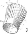
- FIG 3 a perspective view of the lamella basket 4 is given, wherein the annular carrier strip 9 and the plurality of lamellae 5 are shown. It can be seen that each of the lamellae 5 is connected at its respective first end 11 to the annular carrier strip 9, whereas the second end 12 of each lamella 5 is a free end. Thus, the lamellae 5 are resiliently supported by the annular carrier strip 9. The lamellae 5 extend predominantly in the mating direction 10 of the connecting plug 1 towards the front end of the connecting plug 1.
- the annular carrier strip 9 and the lamellae 5 are integrally formed in one piece.
- the lamella basket 4 is formed as a stamped part.
- Each of the lamellae 5 has a contact area 13, 14 that stands out in the radially outward direction of the lamella basket.
- the contact areas 13, 14 are implemented as bulges that protrude in the radially outward direction.
- the contact areas of different sets of lamellae 5 are located at different longitudinal positions when viewed in the mating direction 10 of the connecting plug 1. For example, for a first subset of lamellae, the lamellae's contact areas 13 are located at a first longitudinal position, wherein for a second subset of lamellae 5, the lamellae's contact areas 14 are located at a second longitudinal position, with the first longitudinal position being different from the second longitudinal position.
- the lamellae with the contact area 13 at the first longitudinal position are disposed alternatingly with the lamellae having the contact areas 14 at a respective second longitudinal position.
- the mechanical resistance for inserting the connecting plug 1 into a corresponding socket is reduced.
- the connecting plug 1 is inserted into the socket in the connecting plug's mating direction 10
- the lamellae with the contact areas 13 at the first longitudinal position are pressed in a radially inward direction.
- the connecting plug 1 is further inserted into the corresponding socket, the lamellae 5 with the contact areas 14 located at the respective second longitudinal positions are pressed in the radially inward direction.
- the contact areas 13, 14 are located at two different longitudinal positions, but they may as well be located at three or more longitudinal positions.
- the lamella basket 4 consists of conductive material.
- the lamella basket 4 may for example consist of metal, for example of a copper alloy such as for example a copper-nickel (CuNi) alloy or a copper-chromium (CuCr) alloy.
- the lamella basket 4 may be subjected to plating, for example with gold, silver or copper.
- the base element 2 may be subjected to plating as well.
- the lamella basket 4 may be formed as a stamped part, for example as a stamp-rolled part or as a stamp-bent part.
- the lamella basket 4 shown in figure 3 can be formed by manufacturing a lamella strip and bending the lamella strip in a way that the lamella basket 4 is obtained.
- the connecting plug 1 further comprises a holding element 7 that is at least partly disposed in the interior of the lamella basket 4.
- the holding element 7 comprises a central sleeve 15 and the ring-shaped cap 6 arranged at the front end of the connecting plug 1.
- the ring-shaped cap 6 and the central sleeve 15 may be formed in one piece.
- the ring-shaped cap 6 and the central sleeve 15 may be integrally moulded.
- the ring-shaped cap 6 and the central sleeve 15 can be formed as separate parts.
- the ring-shaped cap 6 has a protruding edge that projects from the central sleeve 15 in a radially outward direction.
- a circumferential groove 16 is located, said groove 16 being configured for accommodating the respective second ends 12 of the lamellae 5.
- the second ends 12 of the lamellae 5 are introduced into the circumferential groove 16.
- the respective second ends 12 of the lamellae 5 are held in place by the sidewalls of the groove 16, wherein a certain moving space for the second ends 12 is provided.
- a recess or one or more indentations may be located at the rear side of the ring-shaped cap 6.
- the lamellae 5 Preferably, for inserting the second ends 12 of the lamellae 5 into the groove 16, the lamellae 5 have to be slightly deformed in a radially inward direction such that the lamellae 5 are pretensioned. Due to this pretension, the alignment of the lamellae 5 is improved.
- the protruding edge of the ring-shaped cap 6 covers the respective second ends 12 of the lamellae 5. The protruding edge prevents that any kind of counterpart can be inserted into an interspace between the lamellae 5 and the holding element 7, which may deform and damage the lamellae 5.
- the ring-shaped cap 6 protects the lamellae 5 from damages.
- the ring-shaped cap 6 provides a touch protection at the front face of the connecting plug 1.
- the ring-shaped cap 6 and preferably the entire holding element 7 may consist of insulating material like for example a plastic material, a polymer material, an elastomer like for example natural rubber or synthetic rubber, etc.
- the ring-shaped cap 6 and preferably the entire holding element 7 can be formed by injection moulding.
- the ring-shaped cap 6 serves as a touch protection at the front face of the connecting plug 1. In case a user inadvertently touches the connecting plug's front face, he or she will not get in contact with live parts of the connecting plug 1.
- the base part 2 comprises a receptacle 17 that may for example be implemented as a cylindrical opening.
- the receptacle 17 is configured for accommodating the annular carrier strip 9 of the lamella basket 4.
- the connecting plug 1 further comprises a supporting sleeve 8 disposed in the interspace between the central sleeve 15 and the lamella basket 4.
- the supporting sleeve 8 comprises a ring-shaped rear part 20 configured for being accommodated in the receptacle 17 of the base element 2. From the rear part 20, the supporting sleeve 8 extends in the direction towards the cap 6 of the holding element 7.
- the supporting sleeve 8 may for example extend up to the contact areas 13, 14 of the lamellae 5.
- the supporting sleeve 8 is configured for providing a rigid support for the lamellae 5.
- the rim of the socket may exert a force on the lamellae 5 and may cause a deformation of the lamellae 5 in a radially inward direction. Due to the presence of the rigid supporting sleeve 8, any plastic deformation of the lamellae 5 is prevented.
- the presence of the supporting sleeve 8 ensures that the lamellae 5 maintain their shape during use of the connecting plug 1.
- the lamella basket 4, the supporting sleeve 8 and the holding element 7 are implemented as rotationally symmetric components.
- the lamella basket 4, the supporting sleeve 8 and the holding element 7 are arranged coaxially with regard to the mating direction 10 of the connecting plug 1.
- the supporting sleeve 8 consists of metal, for example of stainless steel.
- the supporting sleeve 8 may for example be formed by turning or by deep drawing.
- the supporting sleeve may comprise a plurality of supporting lamellae, with the supporting lamellae of the supporting sleeve providing a resilient support for the lamellae 5 of the lamella basket 4. Because of the additional resilient support, the contact force required for deforming the lamellae 5 is increased.
- the advantage of this embodiment is that the relaxation resistance of the lamellae 5 is improved, which means that the spring force of the lamellae 5 can be maintained for a long period of time. This allows for realising a high-performance connector configured for ensuring reliable operation for an extended period of time. In particular, this embodiment allows increasing the upper limit temperature to more than 200°C.
- the connecting plug 1 further comprises the base element 2 configured for holding the lamella basket 4, the supporting sleeve 8 and the holding element 7.
- the base element 2 comprises the receptacle 17, the receptacle 17 being configured for accommodating the annular carrier strip 9 of the lamella basket 4, the rear part 20 of the supporting sleeve 8 and the rear part of the holding element 7.
- the annular carrier strip 9 of the lamella basket 4 is fixed by means of a press fit between the encompassment 21 of the receptacle 17 and the rear part 20 of the supporting sleeve 8.
- the rear part 20 of the supporting sleeve 8 serves as a counterpart of the encompassment 21.
- the annular carrier strip 9 of the lamella basket 4 comprises a plurality of creasings 22. These creasings 22 of the annular carrier strip 9 are configured for being deformed when the press fit is established, thereby improving the press fit. As a result, the annular carrier strip 9 of the lamella basket 4 is tightly fixed between the encompassment 21 of the receptacle 17 and the rear part 20 of the supporting sleeve 8.
- the base element 2 comprises a connecting element 19 configured for fixing the holding element 7, and at the rear end of the holding element 7, a bore hole 18 is located.
- the connecting element 19 extends through the bore hole 18. Then, the holding element 7 can be fixed by subjecting the connecting element 19 to a shaping technique like for example flanging.
- the base element 2 may further comprise a circumferential flange 3 and a bore hole 23 disposed at the rear face of the base element 2.
- the bore hole 23 may be configured for mounting the connecting plug 1 by means of a thread-forming screw.
- the base element 2 may be made of metal, preferably of a copper alloy, such as for example brass or a copper-tellurium (CuTeP) alloy.
- the base element 2 may be formed by turning or by impact extrusion.
- the supporting sleeve 8 only consists of the ring-shaped rear part 20 and does not extend towards the connecting plug's front end.
- the supporting sleeve 8 is provided to serve as a counterpart of the encompassment 21 for establishing a tight press fit.
- the supporting sleeve does not act as a support for the lamellae 5.
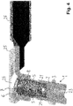
- Figure 4 shows a plug-in connector, with the plug-in connector comprising the connecting plug 1 and a corresponding socket 24.
- the socket 24 may for example be formed by stamping a metal sheet 25.
- a wire 26 may be welded to the metal sheet 25.
- the connecting plug 1 is inserted into the socket 24, with the lamellae 5 of the connecting plug 1 being resiliently deformed in a radially inward direction by the sidewalls of the socket 24.
- a reliable electrical contact is established between the contact areas 13, 14 of the lamellae 5 and the sidewalls of the socket 24.
- a connecting plug with a lamella basket has been described.
- the lamella basket may as well be provided on the part of the socket.
- a socket comprising a lamella basket configured for establishing an electrical contact with a connecting plug is shown.
- FIG 5 gives a perspective view and figure 6 shows a cross-section of a socket 27 together with a corresponding connecting plug 28.
- the socket 27 comprises an annular socket part 29 and a contact plate 30 attached to or integrally formed with the annular socket part 29, wherein both the annular socket part 29 and the contact plate 30 consist of conductive material, preferably of metal.
- the annular socket part 2 and the contact plate 30 may be integrally formed as a deep-drawn part.
- the lamella basket 31 is at least partly disposed in the interior of the annular socket part 29.
- the lamella basket 31 comprises an annular carrier strip 32, a plurality of lamellae 33 and a plurality of outwardly bent straps 34.
- the outwardly bent straps 34 may for example serve as welding straps.
- the mating direction 35 of the socket 27 is indicated with an arrow. When viewed in the mating direction 35, the annular carrier strip 32 is located in the rear part of the lamella basket 31.
- each of the lamellae 33 has a first end 36 and a second end 37, wherein the first end 36 is fixed and the second end 37 is implemented as a free end.
- the first end 36 of each of the lamellae 33 is firmly attached to or integrally moulded with the annular carrier strip 32.
- the lamellae 33 extend from the annular carrier strip 32 along the inner side walls of the annular socket part 29 towards the front end of the socket 27.
- each of the lamellae 33 extends from the annular carrier strip 32 towards the front end of the socket 27 predominantly in the mating direction 35.
- the predominant component of the lamellae's orientation is the component in the mating direction 35.
- Each of the lamellae 33 is a convex curved lamella that stands out in a radially inward direction.
- Each of the lamellae 33 can be resiliently deformed in a radially outward direction.
- the connecting plug 28 is inserted into the socket 27, the lamellae 33 are resiliently deformed in a radially outward direction, whereby an electrical contact is established between the lamellae 33 and the connecting plug 28.
- the lamella basket 31 consists of conductive material, preferably of metal and further preferably of a copper alloy such as for example a copper-nickel (CuNi) alloy or a copper-chromium (CuCr) alloy.
- the lamella basket 31 may be formed as a stamped part, for example as a stamp-rolled part or as a stamp-bent part.
- the lamella basket 31 may be subjected to plating, for example with gold, silver or copper.
- the annular socket part 29 and the contact plate 30 may be subjected to plating as well.
- the lamella basket 31 may be welded to the annular socket part 29.
- the outwardly bent straps 34 may serve as welding straps configured for being welded to the rear portion of the annular socket part 29 at a plurality of welding spots.
- the total area of the welding spots is sufficiently large for establishing an extensive material closure between the lamella basket 31 and the annular socket part 29.
- the lamella basket 31 may for example be fixed to the annular socket part 29 by means of a press ring.
- the press ring may for example be configured for circumferentially pressing the annular carrier strip 32 against the annular socket part 29 in a radially outward direction.
- the press ring may be configured for establishing a press fit between the annular carrier strip 32 and the annular socket part 29.
- the contact plate 30 is configured for establishing an electric connection with a cable 38.
- the contact plate 30 may be electrically connected with a cable lug 39 of the cable 38, wherein a joining technique such as for example ultrasonic welding may be employed.
- the connecting plug 28 comprises a base part 40 consisting of conductive material. Viewed in the connecting plug's mating direction 41, the front end of the base part 40 is implemented as a contact portion 42. When the connecting plug 28 is inserted into the socket 27, an electrical contact is established between the contact portion 42 of the connecting plug 28 and the lamellae 33 of the socket 27.
- the connecting plug 28 further comprises an insulating element 43.
- the front part of the insulating element 43 is implemented as a ring-shaped cap 44 that protrudes in a radially outward direction and covers the front face of the contact portion 42.
- the ring-shaped cap 44 is configured for providing a touch protection at the connecting plug's front face.
- the contact portion 42 comprises a receptacle configured for accommodating the insulating element 43.
- the base part 40 comprises a connecting element that extends through a bore hole of the insulating element 43 and allows for fixing the insulating element 43 by means of a joining technique like for example flanging.
- a bore hole is located, wherein said bore hole may for example be configured for accepting a thread-forming screw.
- each of the lamellae 33 may for example comprise a first section 45 that tapers in the mating direction 35 of the socket 27, a bulge 46 that stands out in a radially inward direction and a second section 47 that widens in the mating direction 35 of the socket 27, with the second section 47 being configured for accepting the connecting plug 28.
- the inner surface of the annular socket part 29 and the rear surface of the resiliently deformed lamellae have a complementary shape.
- the inner surface of the annular socket part 29 serves as a supporting surface 48 for the lamellae 33 when the lamellae 33 are elastically deformed in a radially outward direction.
- the contour of the supporting surface 48 provided by the annular socket part 29 corresponds to the contour of the rear side of the resiliently deformed lamellae.
- the inner surface of the annular socket part 29 comprises a circumferential bulge 49, with the longitudinal position of the bulge 49, viewed in the socket's mating direction 35, corresponding to the longitudinal position of the lamellae's bulge 46.
- the bulge 49 is configured for supporting the bulge 46 of the lamellae 33 when die lamellae 33 are resiliently deformed in a radially outward direction. By providing a supporting surface 48 that matches with the rear surface of the resiliently deformed lamellae, deformation and destruction of the lamellae 33 are prevented.
- the annular socket part 29 and the contact plate 30 may be integrally formed as a deep-drawn part, for example by deep-drawing a copper sheet. Then, the contour of the inner surface of the annular socket part can for example be obtained by subjecting the inner surface of the annular socket part to an additional embossing process. For the inner surface of the annular socket part 29, close manufacturing tolerances have to be obeyed to, but in other areas of the deep-drawn part, wide manufacturing tolerances can be accepted.
Abstract
Description
- The invention relates to a connecting plug with a lamella basket comprising a plurality of lamellae. The invention further relates to a socket with a lamella basket comprising a plurality of lamellae. The invention further relates to a plug-in connector comprising a connecting plug and a socket.
- German utility model
DE 20 2005 015 800 U1 describes a bunch plug with a plurality of wire springs. The plug comprises a base, with the respective first ends of the wire springs being inserted into said base. The plug further comprises a head, with the opposite ends of the wire springs being held in the head, wherein the head is firmly attached to the base. In order to conduct high currents, the wire springs have a contact length that corresponds to about 60% of the available length of the wire springs. - German utility model
DE 1 721 306 U discloses a connector pin formed by wires arranged around a center pin, wherein a cap is mounted to the free end of the center pin, with the cap encompassing the wire ends. The cap is made of electrically conductive material. -
German patent DE 10 2004 002 402 B3 describes an electric cable connection device. The electric cable connection device comprises a contact socket with elongated spring units configured for establishing an electric contact with multiple points of an electrically conductive pin element. The spring units are separated from each other by longitudinal slits. The spring units are pre-curved inwardly in the direction of the electrically conductive pin element in a desired contact area to lead to a contact adjustment of the contact socket on the pin element. - US patent
US 5 667 413 A describes a socket-type electrical connector. A female electrical connector includes a housing defining a generally cylindrical bore therewithin. The connector includes a contact cage disposed, and retained, within the housing. The contact cage includes a number of contact blades disposed so as to provide a radial resilience. In some embodiments, an environmental seal is retained within the housing. The connector provides a high current capacity, low insertion force connector which may be readily fit over post-type electrical terminals. - The object of the invention is to provide a connecting plug that is robust, provides a space-saving design and allows for a reliable operation. A further object of the invention is to provide a socket that is robust and allows for a reliable operation.
- According to the invention, a connecting plug is provided. The connecting plug comprises a lamella basket comprising a plurality of lamellae, each of the lamellae having a first end and a second end, the first end being fixed and the second end being implemented as a free end. The connecting plug further comprises a holding element comprising a central body disposed in the interior of the lamella basket and a cap attached at or integrally moulded with the central body's front end, the cap having a protruding edge that projects from the central body in a radially outward direction, wherein the cap is shaped and configured for accommodating the respective second ends of the lamellae. Furthermore, the connecting plug comprises a base part, with a rear part of the lamella basket being attached to the base part. The lamella basket further comprises an annular carrier strip located at the rear part of the lamella basket, with the first end of each of the lamellae being firmly attached to or integrally moulded with the annular carrier strip, wherein the lamellae extend from the annular carrier strip to the holding element's cap.
- The plug of the present invention comprises a plurality of lamellae, the lamellae being fixed at one end only, with the respective second end of the lamellae being a free end. Because of the free end, the lamellae can adapt to the respective shape of the socket's sidewalls, with the force required for compressing the lamellae being low. The connecting plug comprises a cap at the front end configured for accommodating the free ends of the lamellae, wherein a certain moving space for the respective free ends of the lamellae is provided. The cap is shaped and configured for covering and protecting the lamellae, in order to prevent a deformation or destruction of the lamellae. The lamella basket comprises an annular carrier strip located at the rear part of the lamella basket, wherein the lamella's first ends are firmly attached to the annular carrier strip. Thus all the lamellae are interconnected. Compared to a bunch plug comprising a plurality of wire springs, the lamella basket can be formed as one part, whereby handling and assembly are simplified. Because of the compact size of the lamella basket, it is possible to accomplish a space-saving design of the connecting plug. The rear ends of the lamellae are connected to the annular carrier strip, whereas the front ends are free. This simplifies the insertion of the plug. As the annular carrier strip is located in the rear part of the lamella basket, the annular carrier strip can be fixed to the plug's base part.
- With regard to the connecting plug, terms such as "front end", "rear end", "front face", "rear part" relate to the connecting plug's mating direction. The mating direction of the connecting plug is the direction in which the plug is inserted into a socket. Accordingly, the front end of the connecting plug is the part of the plug that is inserted into the socket first. Also terms like "radially outward direction" or "radially inward direction" relate to the connecting plug's mating direction as the axial direction. An annular carrier strip is a strip of annular shape. Due to a manufacturing process like stamping, an annular carrier strip may comprise a gap. The term "annular carrier strip" denotes a strip that may be continuous or comprise a gap.
- Further according to the invention, a connecting plug is provided. The connecting plug comprises a lamella basket comprising a plurality of lamellae, each of the lamellae having a first end and a second end, the first end being fixed and the second end being implemented as a free end. The connecting plug further comprises a holding element comprising a central body disposed in the interior of the lamella basket and a cap attached at or integrally moulded with the central body's front end, the cap having a protruding edge that projects from the central body in a radially outward direction, wherein the cap is shaped and configured for accommodating the respective second ends of the lamellae. Furthermore, the connecting plug comprises a base part, with a rear part of the lamella basket being attached to the base part. The cap consists of electrically insulating material.
- The connecting plug comprises a lamella basket with a plurality of lamellae that are fixed at one end only, with the respective free ends being accommodated by the cap. The connecting plug's construction is suitable for realising a space-saving design. The cap consists of electrically insulating material. By providing a cap that is made of electrically insulating material, a touch protection at the connecting plug's front face is provided. Thus, it is prevented that the user gets in contact with live parts at the plug's front face.
- Further according to the invention, a connecting plug is provided. The connecting plug comprises a lamella basket comprising a plurality of lamellae, each of the lamellae having a first end and a second end, the first end being fixed and the second end being implemented as a free end. The connecting plug further comprises a holding element comprising a central body disposed in the interior of the lamella basket and a cap attached at or integrally moulded with the central body's front end, the cap having a protruding edge that projects from the central body in a radially outward direction, wherein the cap is shaped and configured for accommodating the respective second ends of the lamellae. Furthermore, the connecting plug comprises a base part, with a rear part of the lamella basket being attached to the base part. The connecting plug comprises a supporting sleeve arranged in the interspace between the lamella basket and the holding element, the supporting sleeve being configured and shaped for providing a support for the lamellae.
- The connecting plug comprises a lamella basket with a plurality of lamellae and a holding element with a central body disposed in the interior of the lamella basket. The connecting plug's construction form is suitable for realising a space-saving design. Between the holding element and the lamella basket, a supporting sleeve is arranged. The supporting sleeve is configured and shaped for providing a mechanical support for the lamellae of the lamella basket. Thus, severe deformation of the lamellae in the radially inward direction is prevented. Even in case the connecting plug is inserted into a socket in a slanted direction, the lamellae are protected from being damaged. The supporting sleeve may for example be a rigid sleeve. Alternatively, the supporting sleeve may for example comprise resilient fingers, the resilient fingers being configured for resiliently supporting the lamellae of the lamella basket.
- Further according to the invention, a plug-in connector is provided, the plug-in connector comprising a connecting plug as described above and a socket, the connecting plug being adapted for being plugged into the socket and for establishing an electrical connection with the socket.
- Yet further according to the invention, a socket is provided. The socket comprises an annular socket part and a lamella basket at least partly disposed in the interior of the annular socket part, the lamella basket comprising a plurality of lamellae and an annular carrier strip located at the rear part of the lamella basket. Each of the lamellae has a first end and a second end, with the first end being firmly attached to or integrally moulded with the annular carrier strip and with the second end being implemented as a free end, with the lamellae extending from the annular carrier strip towards the front end of the socket. The inner surface of the annular socket part comprises a bulge that stands out in a radially inward direction, wherein the bulge of the annular socket part is configured for supporting the lamellae when the lamellae are resiliently deformed in a radially outward direction.
- The socket comprises a lamella basket with a plurality of lamellae and an annular socket part configured for encompassing the lamella basket. The inner surface of the annular socket part comprises a bulge that serves as a mechanical support for the lamellae when the lamellae are deformed in a radially outward direction. The bulge is configured for preventing severe deformation of the lamellae in the radially outward direction. Even in case a connecting plug is inserted into the socket in a slanted direction, the lamellae are protected from being damaged.
- With regard to the socket, terms such as "front end", "rear end", "front face", "rear part" relate to the socket's mating direction. Accordingly, the front end of the socket is the part of the socket that receives the plug's front end first. Also terms like "radially outward direction" or "radially inward direction" relate to the socket's mating direction as the axial direction. An annular carrier strip is a strip of annular shape. Due to a manufacturing process like stamping, an annular carrier strip may comprise a gap. The term "annular carrier strip" denotes a strip that may be continuous or comprise a gap.
- Yet further according to the invention, a plug-in connector is provided, the plug-in connector comprising a socket as described above and a connecting plug, the connecting plug being adapted for being plugged into the socket and for establishing an electrical connection with the socket.
- Preferred features of the invention which may be applied alone or in combination are discussed below and in the dependent claims.
- Preferably, the lamellae are implemented as resilient lamellae. Further preferably, the lamellae are configured for being elastically deformed in a radial direction. For example, when the connecting plug is inserted into a socket, the lamellae may be resiliently compressed in the radially inward direction. The deformed lamellae are pressed against the sidewalls with a certain spring force, thereby establishing an electrical contact of low resistance.
- Preferably, each of the lamellae at the lamella basket's outer surface is a convex curved lamella. Due to the convex shape, the lamellae are smoothly compressed when the plug is inserted into the socket.
- Preferably, the lamella basket comprises an annular carrier strip. Preferably, the annular carrier strip is configured for interconnecting the lamellae. The annular carrier strip provides for an improved stability, wherein handling and assembly of the lamella basket are simplified.
- Preferably, the lamella basket's annular carrier strip is located at the rear part of the lamella basket. Further preferably, the first end of each of the lamellae is firmly attached to the annular carrier strip. Thus, the respective fixed end of each lamella is located in the rear part of the connecting plug, whereas the free end of each lamella faces towards the front end. In a preferred embodiment, the lamellae of the lamella basket are integrally formed with the annular carrier strip. For example, both the annular carrier strip and the plurality of lamellae can be formed in one single piece, which simplifies manufacturing of the lamella basket.
- In a preferred embodiment, the lamellae extend from the annular carrier strip to the holding element's cap. For example, the lamellae may extend from the annular carrier strip along the lateral sides of the connecting plug towards the cap. Preferably, each of the lamellae extends from the annular carrier strip to the holding element's cap predominantly in the mating direction of the connecting plug. Preferably, the predominant component of the lamellae's orientation is the component in the mating direction of the connecting plug. Hence, the lamellae extend predominantly in the connecting plug's mating direction along the sidewalls of the plug.
- Preferably, the lamella basket comprises at least 10 lamellae, further preferably at least 16 lamellae, further preferably at least 20 lamellae, further preferably at least 24 lamellae. Preferably, the lamella basket comprises less than 100 lamellae, further preferably less than 70 lamellae, further preferably less than 50 lamellae, further preferably less than 35 lamellae.
- Preferably, the lamella basket's diameter amounts to at least 30%, further preferably at least 50%, further preferably at least 70%, further preferably at least 90% of the lamella basket's height in the mating direction of the connecting plug. Preferably, the lamella basket's diameter amounts to at most 300%, further preferably at most 200%, further preferably at most 150%, further preferably at most 120% of the lamella basket's height in the mating direction of the connecting plug.
- Preferably, the lamellae extend over at least 50%, further preferably at least 60%, further preferably at least 65% of the lamella basket's height in the mating direction of the connecting plug. Preferably, the lamellae extend over at most 90%, further preferably at most 80%, further preferably at most 75% of the lamella basket's height in the mating direction of the connecting plug. Further preferably, the annular carrier strip extends over at least 10%, further preferably at least 20%, further preferably at least 25% of the lamella basket's height in the mating direction of the connecting plug. Preferably, the annular carrier strip extends over at most 45%, further preferably at most 40%, further preferably at most 35% of the lamella basket's height in the mating direction of the connecting plug.
- Preferably, the lamella basket consists of conductive material. Further preferably, the lamella basket consists of metal, preferably of a copper alloy such as for example a copper-nickel (CuNi) alloy or a copper-chromium (CuCr) alloy. Preferably, the lamellae consist of metal, preferably of a copper alloy like for example a CuNi alloy or a CuCr alloy. Preferably, the annular carrier strip consists of metal, preferably of a copper alloy like for example a CuNi alloy or a CuCr alloy. Preferably, the lamella basket or parts thereof may be subjected to plating, for example with gold, silver or copper. In a preferred embodiment, the lamella basket is formed as a stamped part, further preferably as a stamp-rolled or a stamp-bent part. For example, a lamella strip may be formed by stamping, and then, the lamella strip may be rolled to form the lamella basket.
- Preferably, the cap's protruding edge overlaps with the second ends of the lamellae and is configured for holding the second ends of the lamellae in place. The cap is configured for covering the second ends of the lamellae and for protecting the lamellae from being deformed.
- In a preferred embodiment, the cap comprises a recess or a groove or at least one indentation located at the rear side of the cap. Preferably, the cap comprises a circumferential recess or a circumferential groove or a circumferential indentation located at the rear side of the cap.
- Preferably, the second ends of the lamellae extend into the recess or the groove or the at least one indentation located at the rear side of the cap. For example, the recess or the groove or the at least one indentation located at the rear side of the cap may be configured for accommodating the respective second ends of the lamellae. Preferably, the recess or the groove or the at least one indentation is shaped and configured for providing a predefined moving space to the respective second ends of the lamellae. The recess, the groove or the at least one indentation provides enough moving space to allow for a restricted movement of the second ends of the lamellae. For example, when a lamella is compressed, its second end may be further pushed into the recess, the groove or the indentation. Yet, the lamellae are held in place by the cap, with the cap being configured for protecting the lamellae from being deformed or destroyed.
- Preferably, the cap is shaped and configured for accommodating the respective second ends of the lamellae and for preventing insertion of any counterpart into an interspace between the lamellae and the holding element. Even in case the connecting plug not inserted correctly, deformation and destruction of the lamellae are avoided.
- Preferably, the cap is shaped and configured for pressing the second ends of the lamellae in a radially inward direction and for exerting a pretension onto the lamellae. Due to this pretension, a better alignment of the lamellae is accomplished.
- Preferably, the central body is a solid central body configured for being disposed in the interior of the lamella basket. According to an alternatively preferred embodiment, the central body is a central sleeve configured for being disposed in the interior of the lamella basket. Preferably, the cap is a ring-shaped cap. Further preferably, the holding element comprises a central sleeve and a ring-shaped cap.
- Preferably, the ring-shaped cap's inner diameter is at least 40%, further preferably at least 50%, further preferably at least 55% of the ring-shaped cap's outer diameter. Preferably, the ring-shaped cap's inner diameter is at most 70%, further preferably at most 60%, further preferably at most 55% of the ring-shaped cap's outer diameter.
- Preferably, the cap consists of electrically insulating material. Preferably, the cap consists of at least one of the following: plastic material, polymer material, an elastomer, natural rubber, synthetic rubber. Preferably, the cap is configured for providing a touch protection at the connecting plug's front face. By providing a cap made of insulating material at the plug's front face, it is prevented that the user gets in contact with live parts at the plug's front face.
- Preferably, the holding element is an insulating element. Preferably, the holding element consists of insulating material, in particular of at least one of the following: plastic material, polymer material, an elastomer, natural rubber, synthetic rubber. Preferably, the holding element is an injection moulded part.
- Preferably, each lamella comprises at least one contact area. Further preferably, each lamella comprises a contact area that stands out in the radially outward direction, said contact area being configured for establishing an electrical contact with a socket. For example, the contact area that stands out in a radially outward direction may be pressed against the sidewalls of the socket. Preferably, each lamella comprises a contact area, the contact area being a bulge of the lamella that stands out in a radially outward direction of the connecting plug.
- Preferably, the connecting plug is configured for being inserted into a socket and for establishing an electric contact with the socket. Preferably, the lamellae are configured for establishing an electrical connection with side walls of a socket when plugged into the socket.
- In a preferred embodiment, respective contact areas of the various lamellae are located at at least two different longitudinal positions when viewed in the mating direction of the connecting plug. When the connecting plug is inserted into the socket, different subsets of the lamellae are deformed subsequently at different points of time. As the force required for deforming a subset of the lamellae is smaller than the force required for deforming all the lamellae, the total insertion force is reduced.
- Preferably, for a first subset of lamellae, the lamellae's contact areas are located at a first longitudinal position, wherein for a second subset of lamellae, the lamellae's contact areas are located at a second longitudinal position, wherein the lamellae of the first and the second subset are disposed alternatingly around the circumference of the lamella basket, the second longitudinal position being different from the first longitudinal position.
- In a preferred embodiment, the connecting plug comprises a supporting sleeve arranged in the interspace between the lamella basket and the holding element. Preferably, the supporting sleeve is a sleeve of essentially cylindrical shape. Preferably, the supporting sleeve extends in the mating direction of the connecting plug and is configured and shaped for providing a support for the lamellae. The supporting sleeve may for example be configured for preventing a deformation of the lamellae in a radially inward direction. Preferably, the supporting sleeve extends in the mating direction and is configured and shaped for preventing a plastic deformation of the lamellae. For example, in case the connecting plug is inserted into the socket in a slanted orientation, severe deformation of the lamellae is prevented.
- Preferably, the supporting sleeve extends in the connecting plug's mating direction and comprises a plurality of supporting lamellae, the supporting lamellae being configured for resiliently supporting the lamellae of the lamella basket. Further preferably, the supporting lamellae of the supporting sleeve are configured for resiliently supporting the lamellae of the lamella basket and for augmenting the contact normal force of the lamella basket's lamellae. The advantage of this embodiment is that the relaxation resistance of the lamellae is improved. This embodiment is particularly suitable for high-temperature environments, e.g. with temperature of above 200 °C, where due to the temperature the elasticity of the lamellae of the lamella basket may be compromised. The lamellae of the lamella basket and the supporting lamellae of the supporting sleeve element preferably are made of different materials. In general, materials with a high electrical conductivity have a lower relaxation temperature, resulting in a reduced resilience at high temperatures. By choosing different materials for the lamellae of the lamella basket and the supporting lamellae of the supporting sleeve, advantageously a high electrical conductivity and a sufficient resilience at high temperature can be achieved. Preferably, both materials are metals. The lamella basket preferably has a higher electrical conductivity than the supporting sleeve. The supporting sleeve preferably has a higher relaxation temperature than the lamella basket. Preferably, the relaxation temperature of the material of the supporting sleeve is above 250 °C, more preferably above 300 °C. The relaxation temperature of the material of the lamella basket preferably is below 200 °C, more preferably below 160 °C. Preferably, the lamella basket is made of copper or a material comprising copper, e.g. a copper alloy. Copper has a relaxation temperature of approximately 100 °C, copper/tin alloy typically has a relaxation temperature of between 120 and 130 °C, and copper/beryllium alloy typically has a relaxation temperature of between 140 and 150 °C. The supporting sleeve preferably is made of steel, more preferably of stainless steel. The relaxation temperature of stainless steel typically is above 300 °C. Thus, even at temperature as high as 250 °C or even 300 °C high electrical conductivity and sufficient resilience can be achieved.
- Preferably, the supporting sleeve consists of metal, preferably of steel, for example of stainless steel. Further preferably, the supporting sleeve is a turned part or a deep drawn part.
- According to a preferred embodiment, the base part comprises a receptacle at its front end, the receptacle being configured for accommodating the lamella basket's annular carrier strip. Preferably, the receptacle is configured for accommodating the lamella basket's annular carrier strip and at least one of the holding element and a supporting sleeve.
- Preferably, at least one of the following components is rotationally symmetric: the lamella basket, the holding element, a supporting sleeve, the base part, with a respective axis of rotation corresponding to the mating direction of the connecting plug. Preferably, the lamella basket's annular carrier strip, a rear part of the holding element and a rear part of a supporting sleeve are arranged coaxially.
- Preferably, the lamella basket's annular carrier strip is configured for being fixed in the receptacle by means of a press fit. A press fit allows for establishing a stable connection between the lamella basket and the base part. Further preferably, the connecting plug comprises a supporting sleeve arranged in the interior of the lamella basket, the supporting sleeve being configured for acting as a counterpart of the encompassment of the base part's receptacle when establishing the press fit. Preferably, the lamella basket's annular carrier strip is tightly fixed between the supporting sleeve and the base part's receptacle. Further preferably, both the lamella basket's annular carrier strip and a rear part of the supporting sleeve are fixed in the receptacle by means of a press fit.
- Preferably, the lamella basket's annular carrier strip comprises at least one creasing, wherein at least one of the creasings is deformed when establishing the press fit. By deforming the creasings, a more stable press fit and an improved current transfer are accomplished.
- According to a preferred embodiment, the holding element is fastened on the base part. Preferably, the base part comprises a connecting element located at the bottom of the receptacle, the connecting element being configured for fixing the holding element disposed in the interior of the lamella basket. Further preferably, the connecting element is configured for extending through a bore hole at the bottom of the holding element, wherein the connecting element is configured for being fastened by flanging. Preferably, the base part comprises a bore hole at its rear end, the bore hole being configured for mounting the base part by means of a thread forming screw.
- Preferably, the base part consists of conductive material. Further preferably, the base part consists of metal, in particular of a copper alloy, such as for example brass or a copper-tellurium (CuTeP) alloy. Further preferably, the base part is a turned part or a part formed by impact extrusion.
- A plug-in connector according to the invention comprises a connecting plug as described above and a socket, the connecting plug being adapted for being plugged into the socket and for establishing an electrical connection with the socket. Preferably, the socket is a stamped part. Further preferably, the socket is made of sheet material.
- Preferably, the lamellae are implemented as resilient lamellae. Further preferably, the lamellae are configured for being elastically deformed in a radially outward direction. For example, when a plug is inserted into a socket, the lamellae may be resiliently deformed in the radially outward direction. The deformed lamellae of the socket are pressed against the plug with a certain spring force, thereby establishing an electrical contact of low resistance.
- Preferably, the annular carrier strip is configured for interconnecting the lamellae. The annular carrier strip provides for an improved stability, wherein handling and assembly of the lamella basket are simplified.
- Preferably, the lamella basket's annular carrier strip is located at the rear part of the lamella basket when viewed in the socket's mating direction. Preferably, the first end of each of the lamellae is firmly attached to the annular carrier strip. Thus, the respective fixed end of each lamella is located in the rear part of the socket, whereas the free end of each lamella faces towards the front end of the socket. Hence, a plug may for example be inserted with low insertion force. In a preferred embodiment, the lamellae of the lamella basket are integrally formed with the annular carrier strip. For example, the annular carrier strip and the plurality of lamellae can be formed in one single piece.
- Preferably, the lamellae extend from the annular carrier strip along the inner surface of the annular socket part towards the front end of the socket. The lamellae may for example extend along the inner sidewalls of the annular socket part. Preferably, each of the lamellae extends from the annular carrier strip to the front end of the socket predominantly in the mating direction of the socket. Preferably, the predominant component of the lamellae's orientation is the component in the mating direction of the socket.
- According to a preferred embodiment, the contour of the annular socket part's inner surface corresponds to the contour of the rear side of a resiliently deformed lamella. Preferably, the inner surface of the annular socket part and the rear surface of a resiliently deformed lamella are of complementary shape. Thus the inner surface of the annular socket part can serve as a support for the lamellae. Preferably, the inner surface of the annular socket part is configured for acting as a supporting surface for the lamellae when the lamellae are resiliently deformed in a radially outward direction. Preferably, a supporting surface is a surface configured for supporting the resiliently deformed lamellae in a way that they are not damaged.
- Preferably, the rear surface of the resiliently deformed lamellae is a concave shaped surface. Further preferably, the inner surface of the annular socket part is a convex curved surface that stands out in a radially inward direction. In this regard, the inner surface of the annular socket part is shaped and configured for supporting the rear surface of the lamellae.
- Preferably, the contour of the annular socket part's inner surface corresponds to a deflection curve of the resiliently deformed lamellae. For example, the deflection curve of the resiliently deformed lamellae may be determined in advance. In this regard, each lamella may for example be treated as a bending beam. Preferably, for calculating the deflection curve, the progression of the area moments of inertia along the lamella is taken into account. For example, a lamella may taper in the direction from the fixed end to the free end, which means that the cross sectional area of a lamella decreases in the direction towards the lamella's free end. Also in a case like this, the deflection curve is capable of considering the specific shape of the lamella, because the progression of the area moment of inertia along the lamella is taken into account when determining the deflection curve.
- Preferably, at least one of the lamellae comprises a bulge that stands out in a radially inward direction. For example, the bulge may be configured as a contact area configured for establishing an electric connection with a contact portion of a connecting plug. Preferably, each of the lamellae comprises a bulge that stands out in a radially inward direction. Further preferably, the bulge of the annular socket part is configured for supporting the respective bulge of the lamellae when the lamellae are resiliently deformed in a radially outward direction. In this regard, the shape of the lamellae's bulge may for example correspond to the shape of the annular socket part's bulge. For example, the bulge of the annular socket part may be a circumferential bulge. Preferably, the longitudinal position of the lamellae's bulge corresponds to the longitudinal position of the annular socket part's bulge, with the annular socket part's bulge being configured for supporting the lamellae's bulge when the lamellae are resiliently deformed in a radially outward direction. In a yet further preferred embodiment, the longitudinal position of the lamellae's bulge and the longitudinal position of the annular socket part's bulge are within a longitudinal range of 15% of the socket's dimension when viewed in the socket's mating direction. Preferably, the annular socket part's bulge is part of the supporting surface provided by the annular socket part.
- When viewed in the mating direction of the socket, each of the lamellae may for example comprise a first section that tapers in the mating direction of the socket, a bulge that stands out in a radially inward direction and a second section that widens in the mating direction of the socket. Preferably, the lamellae's second sections are configured for accepting a connecting plug when the connecting plug is inserted into the socket.
- According to a preferred embodiment, the inner surface of the annular socket part is implemented as a supporting surface for the lamellae. Preferably, the inner surface of the annular socket part is configured for acting as a supporting surface for the lamellae when the lamellae are resiliently deformed in a radially outward direction. The supporting surface may for example be configured for preventing a plastic deformation of the lamellae when the lamellae are deformed in a radially outward direction.
- Preferably, between the lamella basket and the annular socket part, both a mechanical attachment and an electrical connection are established. Preferably, the lamella basket is joined with the annular socket part by welding. For example, the lamella basket may comprise a plurality of welding straps disposed at the rear end of the lamella basket. Preferably, the welding straps are evenly arranged along the perimeter of the lamella basket's rear end. Preferably, the welding straps are bent in a radially outward direction. Further preferably, the welding straps are configured for being welded to the annular socket part at a plurality of welding spots. Thus, the lamella basket can be joined with the annular socket part at a plurality of welding points, thereby establishing both a mechanical attachment and an electrical connection of low resistance. Preferably, the welding straps are configured for being welded to the annular socket part at a plurality of welding spots circumferentially arranged at the rear rim of the annular socket part. As the mechanical attachment is established at a plurality of welding spots, the lamella basket is evenly fixed along its perimeter. A warped or contorted attachment due to uneven fastening is prevented. Preferably, the welding straps of the lamella basket are configured for establishing an extensive material bond with the annular socket part.
- According to an alternatively preferred embodiment, the socket comprises a press ring arranged in the interior of the lamella basket, the press ring being configured for pressing the lamella basket against the annular socket part in a radially outward direction. Preferably, the press ring is configured for circumferentially pressing the lamella basket against the annular socket part from the inside out. Preferably, the press ring is configured for fixing the lamella basket by means of a press fit. Preferably, the annular carrier strip of the lamella basket comprises a plurality of creasings configured for providing an improved press fit. Preferably, the press ring consists of metal, preferably of steel, for example of stainless steel.
- Preferably, the lamella basket consists of conductive material, preferably of metal. Further preferably, the lamella basket consists of a copper alloy such as for example a copper-nickel (CuNi) alloy or a copper-chromium (CuCr) alloy. The lamella basket may for example be formed as a stamped part, preferably as a stamp-rolled or a stamp-bent part. The annular socket part may for example consist of conductive material, preferably of metal. Further preferably, the annular socket part consists of copper or of a copper alloy. In a preferred embodiment, the annular socket part is a deep drawn part. Preferably, the annular socket part is formed by deep drawing a metal sheet, preferably a sheet of copper or of a copper alloy. Preferably, the contour of the inner surface of the annular socket part is obtained by subjecting the inner surface of the annular socket part to an embossing process. Further preferably, embossing is performed using an embossing tool, with the outer contour of the embossing tool corresponding to the envisaged contour of the annular socket part's inner surface.
- Preferably, the annular socket part is integrally formed with a contact plate configured for being electrically connected with a cable. Preferably, the annular socket part and the contact plate are formed by deep drawing a metal sheet, preferably a sheet of copper or of a copper alloy.
- A plug-in connector according to the invention comprises a socket as described above and a connecting plug, the connecting plug being adapted for being plugged into the socket and for establishing an electrical connection with the socket.
- Preferably, the plug comprises a base part and an insulating element, wherein the base part comprises a contact portion configured for establishing an electrical contact with the socket. Further preferably, the contact portion comprises a receptacle configured for accommodating the insulating element. Preferably, the insulating element comprises a ring-shaped cap arranged at the front end of the insulating element, wherein the ring-shaped cap is configured for covering a front face of the connecting plug's contact portion. Preferably, the ring-shaped cap is configured for providing a touch protection at the connecting plug's front face.
- The invention is illustrated in greater detail with the aid of schematic drawings.
- It shows schematically:
-
Figure 1 shows two different views of a connecting plug. -
Figure 2 shows a cross-sectional view of the connecting plug. -
Figure 3 shows a perspective view of the lamella basket. -
Figure 4 shows a plug-in connector comprising a connecting plug and a socket. -
Figure 5 shows a perspective view of a socket with a lamella basket together with a connecting plug. -
Figure 6 shows a cross-sectional view of the socket with a lamella basket together with a connecting plug. -
Figure 7A shows how the connecting plug is inserted into the socket. -
Figure 7B shows how an electric contact between the connecting plug and the socket's lamella basket is established. - In the following description of preferred embodiments of the present invention, identical reference numerals denote identical or comparable components.
-
Figure 1 shows two perspective views of a connectingplug 1 according to embodiments of the present invention. The connectingplug 1 comprises abase element 2 with acircumferential flange 3, alamella basket 4 with a plurality oflamellae 5 and a ring-shapedcap 6 disposed at the connecting plug's front face. The connectingplug 1 is configured for being inserted into a corresponding socket. When the connectingplug 1 is plugged into the socket, thelamellae 5 are pressed against the lateral walls of the socket and establish an electrical connection between the connectingplug 1 and the socket. -
Figure 2 shows a cross-sectional view of the connectingplug 1 and its components. The connectingplug 1 comprises thebase element 2, thelamella basket 4 with the plurality oflamellae 5 and a holdingelement 7 with the ring-shapedcap 6. The connectingplug 1 further comprises a supportingsleeve 8 disposed in the interspace between thelamella basket 4 and the holdingelement 7. Thelamella basket 4 comprises anannular carrier strip 9 and a plurality oflamellae 5. Themating direction 10 of the connectingplug 1 is indicated with an arrow. When viewed in themating direction 10 of the connectingplug 1, theannular carrier strip 9 of thelamella basket 4 is disposed at the rear end of thelamella basket 4, with thelamellae 5 extending from theannular carrier strip 9 to the ring-shapedcap 6 predominantly in themating direction 10 of the connectingplug 1. For eachlamella 5, only the respectivefirst end 11 is affixed to theannular carrier strip 9, whereas thesecond end 12 is implemented as a free end. Thelamellae 5 are implemented as resilient metal strips and accordingly, eachlamella 5 can be elastically deformed in a radially inward direction. - In
figure 3 , a perspective view of thelamella basket 4 is given, wherein theannular carrier strip 9 and the plurality oflamellae 5 are shown. It can be seen that each of thelamellae 5 is connected at its respectivefirst end 11 to theannular carrier strip 9, whereas thesecond end 12 of eachlamella 5 is a free end. Thus, thelamellae 5 are resiliently supported by theannular carrier strip 9. Thelamellae 5 extend predominantly in themating direction 10 of the connectingplug 1 towards the front end of the connectingplug 1. In a preferred embodiment, theannular carrier strip 9 and thelamellae 5 are integrally formed in one piece. Preferably, thelamella basket 4 is formed as a stamped part. - Each of the
lamellae 5 has acontact area contact areas lamellae 5 are located at different longitudinal positions when viewed in themating direction 10 of the connectingplug 1. For example, for a first subset of lamellae, the lamellae'scontact areas 13 are located at a first longitudinal position, wherein for a second subset oflamellae 5, the lamellae'scontact areas 14 are located at a second longitudinal position, with the first longitudinal position being different from the second longitudinal position. As shown infigure 3 , the lamellae with thecontact area 13 at the first longitudinal position are disposed alternatingly with the lamellae having thecontact areas 14 at a respective second longitudinal position. By arranging the contact areas of thelamellae 5 at different longitudinal positions, the mechanical resistance for inserting the connectingplug 1 into a corresponding socket is reduced. When the connectingplug 1 is inserted into the socket in the connecting plug'smating direction 10, first, the lamellae with thecontact areas 13 at the first longitudinal position are pressed in a radially inward direction. When the connectingplug 1 is further inserted into the corresponding socket, thelamellae 5 with thecontact areas 14 located at the respective second longitudinal positions are pressed in the radially inward direction. Instead of deforming all thelamellae 5 at the same time, different subsets of the lamellae are deformed one after the other and thus, the overall mechanical resistance is decreased and the insertion force is reduced. In the example shown infigures 2 and3 , thecontact areas - The
lamella basket 4 consists of conductive material. Thelamella basket 4 may for example consist of metal, for example of a copper alloy such as for example a copper-nickel (CuNi) alloy or a copper-chromium (CuCr) alloy. In order to provide for an improved electrical contact, thelamella basket 4 may be subjected to plating, for example with gold, silver or copper. Additionally or alternatively, thebase element 2 may be subjected to plating as well. Thelamella basket 4 may be formed as a stamped part, for example as a stamp-rolled part or as a stamp-bent part. In particular, thelamella basket 4 shown infigure 3 can be formed by manufacturing a lamella strip and bending the lamella strip in a way that thelamella basket 4 is obtained. - As shown in
figure 2 , the connectingplug 1 further comprises a holdingelement 7 that is at least partly disposed in the interior of thelamella basket 4. The holdingelement 7 comprises acentral sleeve 15 and the ring-shapedcap 6 arranged at the front end of the connectingplug 1. The ring-shapedcap 6 and thecentral sleeve 15 may be formed in one piece. For example, the ring-shapedcap 6 and thecentral sleeve 15 may be integrally moulded. Alternatively, the ring-shapedcap 6 and thecentral sleeve 15 can be formed as separate parts. - The ring-shaped
cap 6 has a protruding edge that projects from thecentral sleeve 15 in a radially outward direction. At the rear side of the ring-shapedcap 6, acircumferential groove 16 is located, saidgroove 16 being configured for accommodating the respective second ends 12 of thelamellae 5. When inserting the holdingelement 7 into the interior of thelamella basket 4, the second ends 12 of thelamellae 5 are introduced into thecircumferential groove 16. Thus, the respective second ends 12 of thelamellae 5 are held in place by the sidewalls of thegroove 16, wherein a certain moving space for the second ends 12 is provided. Instead of agroove 16, a recess or one or more indentations may be located at the rear side of the ring-shapedcap 6. - Preferably, for inserting the second ends 12 of the
lamellae 5 into thegroove 16, thelamellae 5 have to be slightly deformed in a radially inward direction such that thelamellae 5 are pretensioned. Due to this pretension, the alignment of thelamellae 5 is improved. The protruding edge of the ring-shapedcap 6 covers the respective second ends 12 of thelamellae 5. The protruding edge prevents that any kind of counterpart can be inserted into an interspace between thelamellae 5 and the holdingelement 7, which may deform and damage thelamellae 5. Thus, the ring-shapedcap 6 protects thelamellae 5 from damages. - The ring-shaped
cap 6 provides a touch protection at the front face of the connectingplug 1. The ring-shapedcap 6 and preferably theentire holding element 7 may consist of insulating material like for example a plastic material, a polymer material, an elastomer like for example natural rubber or synthetic rubber, etc. The ring-shapedcap 6 and preferably theentire holding element 7 can be formed by injection moulding. The ring-shapedcap 6 serves as a touch protection at the front face of the connectingplug 1. In case a user inadvertently touches the connecting plug's front face, he or she will not get in contact with live parts of the connectingplug 1. - The
base part 2 comprises areceptacle 17 that may for example be implemented as a cylindrical opening. Thereceptacle 17 is configured for accommodating theannular carrier strip 9 of thelamella basket 4. - The connecting
plug 1 further comprises a supportingsleeve 8 disposed in the interspace between thecentral sleeve 15 and thelamella basket 4. The supportingsleeve 8 comprises a ring-shapedrear part 20 configured for being accommodated in thereceptacle 17 of thebase element 2. From therear part 20, the supportingsleeve 8 extends in the direction towards thecap 6 of the holdingelement 7. The supportingsleeve 8 may for example extend up to thecontact areas lamellae 5. The supportingsleeve 8 is configured for providing a rigid support for thelamellae 5. In particular, in case the connecting plug is inserted into a socket in a slanted direction, the rim of the socket may exert a force on thelamellae 5 and may cause a deformation of thelamellae 5 in a radially inward direction. Due to the presence of the rigid supportingsleeve 8, any plastic deformation of thelamellae 5 is prevented. The presence of the supportingsleeve 8 ensures that thelamellae 5 maintain their shape during use of the connectingplug 1. Preferably, thelamella basket 4, the supportingsleeve 8 and the holdingelement 7 are implemented as rotationally symmetric components. Further preferably, thelamella basket 4, the supportingsleeve 8 and the holdingelement 7 are arranged coaxially with regard to themating direction 10 of the connecting plug 1.Preferably, the supportingsleeve 8 consists of metal, for example of stainless steel. The supportingsleeve 8 may for example be formed by turning or by deep drawing. - According to a preferred embodiment which is not shown in the figures, the supporting sleeve may comprise a plurality of supporting lamellae, with the supporting lamellae of the supporting sleeve providing a resilient support for the
lamellae 5 of thelamella basket 4. Because of the additional resilient support, the contact force required for deforming thelamellae 5 is increased. The advantage of this embodiment is that the relaxation resistance of thelamellae 5 is improved, which means that the spring force of thelamellae 5 can be maintained for a long period of time. This allows for realising a high-performance connector configured for ensuring reliable operation for an extended period of time. In particular, this embodiment allows increasing the upper limit temperature to more than 200°C. - The connecting
plug 1 further comprises thebase element 2 configured for holding thelamella basket 4, the supportingsleeve 8 and the holdingelement 7. Thebase element 2 comprises thereceptacle 17, thereceptacle 17 being configured for accommodating theannular carrier strip 9 of thelamella basket 4, therear part 20 of the supportingsleeve 8 and the rear part of the holdingelement 7. Theannular carrier strip 9 of thelamella basket 4 is fixed by means of a press fit between theencompassment 21 of thereceptacle 17 and therear part 20 of the supportingsleeve 8. In this respect, therear part 20 of the supportingsleeve 8 serves as a counterpart of theencompassment 21. As shown infigure 3 , theannular carrier strip 9 of thelamella basket 4 comprises a plurality ofcreasings 22. Thesecreasings 22 of theannular carrier strip 9 are configured for being deformed when the press fit is established, thereby improving the press fit. As a result, theannular carrier strip 9 of thelamella basket 4 is tightly fixed between theencompassment 21 of thereceptacle 17 and therear part 20 of the supportingsleeve 8. - After the
annular carrier strip 9 of thelamella basket 4 and therear part 20 of the supportingsleeve 8 are fastened, the holdingelement 7 is inserted into the interior of thelamella basket 4 and the supportingsleeve 8. Thebase element 2 comprises a connectingelement 19 configured for fixing the holdingelement 7, and at the rear end of the holdingelement 7, abore hole 18 is located. When the holdingelement 7 is inserted, the connectingelement 19 extends through thebore hole 18. Then, the holdingelement 7 can be fixed by subjecting the connectingelement 19 to a shaping technique like for example flanging. - The
base element 2 may further comprise acircumferential flange 3 and abore hole 23 disposed at the rear face of thebase element 2. Thebore hole 23 may be configured for mounting the connectingplug 1 by means of a thread-forming screw. Thebase element 2 may be made of metal, preferably of a copper alloy, such as for example brass or a copper-tellurium (CuTeP) alloy. Thebase element 2 may be formed by turning or by impact extrusion. - According to an alternative embodiment which is not shown in the figures, the supporting
sleeve 8 only consists of the ring-shapedrear part 20 and does not extend towards the connecting plug's front end. In this embodiment, the supportingsleeve 8 is provided to serve as a counterpart of theencompassment 21 for establishing a tight press fit. The supporting sleeve does not act as a support for thelamellae 5. -
Figure 4 shows a plug-in connector, with the plug-in connector comprising the connectingplug 1 and a correspondingsocket 24. Thesocket 24 may for example be formed by stamping ametal sheet 25. For electrically connecting thesocket 24, awire 26 may be welded to themetal sheet 25. Infigure 4 , the connectingplug 1 is inserted into thesocket 24, with thelamellae 5 of the connectingplug 1 being resiliently deformed in a radially inward direction by the sidewalls of thesocket 24. Thus, a reliable electrical contact is established between thecontact areas lamellae 5 and the sidewalls of thesocket 24. - In the embodiment shown in
figures 1 to 4 , a connecting plug with a lamella basket has been described. Alternatively, the lamella basket may as well be provided on the part of the socket. Infigures 5 to 7B , a socket comprising a lamella basket configured for establishing an electrical contact with a connecting plug is shown. -
Figure 5 gives a perspective view andfigure 6 shows a cross-section of asocket 27 together with a corresponding connectingplug 28. Thesocket 27 comprises anannular socket part 29 and acontact plate 30 attached to or integrally formed with theannular socket part 29, wherein both theannular socket part 29 and thecontact plate 30 consist of conductive material, preferably of metal. For example, theannular socket part 2 and thecontact plate 30 may be integrally formed as a deep-drawn part. - The
lamella basket 31 is at least partly disposed in the interior of theannular socket part 29. Thelamella basket 31 comprises anannular carrier strip 32, a plurality oflamellae 33 and a plurality of outwardly bent straps 34. The outwardlybent straps 34 may for example serve as welding straps. Themating direction 35 of thesocket 27 is indicated with an arrow. When viewed in themating direction 35, theannular carrier strip 32 is located in the rear part of thelamella basket 31. - As shown in
figure 7A and 7B , each of thelamellae 33 has afirst end 36 and asecond end 37, wherein thefirst end 36 is fixed and thesecond end 37 is implemented as a free end. Thefirst end 36 of each of thelamellae 33 is firmly attached to or integrally moulded with theannular carrier strip 32. Thelamellae 33 extend from theannular carrier strip 32 along the inner side walls of theannular socket part 29 towards the front end of thesocket 27. Preferably, each of thelamellae 33 extends from theannular carrier strip 32 towards the front end of thesocket 27 predominantly in themating direction 35. In this regard, the predominant component of the lamellae's orientation is the component in themating direction 35. Each of thelamellae 33 is a convex curved lamella that stands out in a radially inward direction. Each of thelamellae 33 can be resiliently deformed in a radially outward direction. In case the connectingplug 28 is inserted into thesocket 27, thelamellae 33 are resiliently deformed in a radially outward direction, whereby an electrical contact is established between thelamellae 33 and the connectingplug 28. - The
lamella basket 31 consists of conductive material, preferably of metal and further preferably of a copper alloy such as for example a copper-nickel (CuNi) alloy or a copper-chromium (CuCr) alloy. Thelamella basket 31 may be formed as a stamped part, for example as a stamp-rolled part or as a stamp-bent part. For improving the electrical contact, thelamella basket 31 may be subjected to plating, for example with gold, silver or copper. Additionally or alternatively, theannular socket part 29 and thecontact plate 30 may be subjected to plating as well. - For mechanically and electrically connecting the
lamella basket 31 with theannular socket part 29, thelamella basket 31 may be welded to theannular socket part 29. In this regard, the outwardlybent straps 34 may serve as welding straps configured for being welded to the rear portion of theannular socket part 29 at a plurality of welding spots. The total area of the welding spots is sufficiently large for establishing an extensive material closure between thelamella basket 31 and theannular socket part 29. Thus, both a mechanical fixing and an electrical connection are established between thelamella basket 31 and theannular socket part 29. According to an alternative solution, thelamella basket 31 may for example be fixed to theannular socket part 29 by means of a press ring. The press ring may for example be configured for circumferentially pressing theannular carrier strip 32 against theannular socket part 29 in a radially outward direction. The press ring may be configured for establishing a press fit between theannular carrier strip 32 and theannular socket part 29. - The
contact plate 30 is configured for establishing an electric connection with acable 38. For example, thecontact plate 30 may be electrically connected with acable lug 39 of thecable 38, wherein a joining technique such as for example ultrasonic welding may be employed. - The connecting
plug 28 comprises abase part 40 consisting of conductive material. Viewed in the connecting plug's mating direction 41, the front end of thebase part 40 is implemented as acontact portion 42. When the connectingplug 28 is inserted into thesocket 27, an electrical contact is established between thecontact portion 42 of the connectingplug 28 and thelamellae 33 of thesocket 27. The connectingplug 28 further comprises an insulatingelement 43. The front part of the insulatingelement 43 is implemented as a ring-shapedcap 44 that protrudes in a radially outward direction and covers the front face of thecontact portion 42. The ring-shapedcap 44 is configured for providing a touch protection at the connecting plug's front face. In order to fix the insulatingelement 43, thecontact portion 42 comprises a receptacle configured for accommodating the insulatingelement 43. Furthermore, thebase part 40 comprises a connecting element that extends through a bore hole of the insulatingelement 43 and allows for fixing the insulatingelement 43 by means of a joining technique like for example flanging. At the rear end of thebase part 40, a bore hole is located, wherein said bore hole may for example be configured for accepting a thread-forming screw. - As shown in
figure 7A and 7B , when the connectingplug 28 is inserted into thesocket 27, thelamellae 33 are elastically deformed in a radially outward direction. As the connectingplug 28 is further inserted into thesocket 27, thelamellae 33 are resiliently pressed against thecontact portion 42 such that an electrical contact between thelamella basket 31 and thecontact portion 42 is established. Each of thelamellae 33 may for example comprise afirst section 45 that tapers in themating direction 35 of thesocket 27, abulge 46 that stands out in a radially inward direction and asecond section 47 that widens in themating direction 35 of thesocket 27, with thesecond section 47 being configured for accepting the connectingplug 28. The inner surface of theannular socket part 29 and the rear surface of the resiliently deformed lamellae have a complementary shape. Thus, the inner surface of theannular socket part 29 serves as a supportingsurface 48 for thelamellae 33 when thelamellae 33 are elastically deformed in a radially outward direction. Preferably, the contour of the supportingsurface 48 provided by theannular socket part 29 corresponds to the contour of the rear side of the resiliently deformed lamellae. The inner surface of theannular socket part 29 comprises acircumferential bulge 49, with the longitudinal position of thebulge 49, viewed in the socket'smating direction 35, corresponding to the longitudinal position of the lamellae'sbulge 46. Thebulge 49 is configured for supporting thebulge 46 of thelamellae 33 whendie lamellae 33 are resiliently deformed in a radially outward direction. By providing a supportingsurface 48 that matches with the rear surface of the resiliently deformed lamellae, deformation and destruction of thelamellae 33 are prevented. - The
annular socket part 29 and thecontact plate 30 may be integrally formed as a deep-drawn part, for example by deep-drawing a copper sheet. Then, the contour of the inner surface of the annular socket part can for example be obtained by subjecting the inner surface of the annular socket part to an additional embossing process. For the inner surface of theannular socket part 29, close manufacturing tolerances have to be obeyed to, but in other areas of the deep-drawn part, wide manufacturing tolerances can be accepted. - The features described in the above description, claims and figures can be relevant to the invention in any combination. Their reference numerals in the claims have merely been introduced to facilitate reading of the claims. They are by no means meant to be limiting.
-
- 1
- connecting plug
- 2
- base element
- 3
- flange
- 4
- lamella basket
- 5
- lamellae
- 6
- ring-shaped cap
- 7
- holding element
- 8
- supporting sleeve
- 9
- annular carrier strip
- 10
- mating direction of the connecting plug
- 11
- first end of lamella
- 12
- second end of lamella
- 13
- contact area of first subset of lamellae
- 14
- contact area of second subset of lamellae
- 15
- central sleeve
- 16
- groove
- 17
- receptacle
- 18
- bore hole
- 19
- connecting element
- 20
- rear part of supporting sleeve
- 21
- encompassment
- 22
- creasings
- 23
- bore hole
- 24
- socket
- 25
- metal sheet
- 26
- wire
- 27
- socket
- 28
- connecting plug
- 29
- annular socket part
- 30
- contact plate
- 31
- lamella basket
- 32
- annular carrier strip
- 33
- lamellae
- 34
- outwardly bent straps
- 35
- mating direction of socket
- 36
- first end of lamellae
- 37
- second end of lamellae
- 38
- cable
- 39
- cable lug
- 40
- base part
- 41
- mating direction of connecting plug
- 42
- contact portion
- 43
- insulating element
- 44
- ring-shaped cap
- 45
- first section of lamellae
- 46
- bulge
- 47
- second section of lamellae
- 48
- supporting surface
- 49
- bulge
Claims (15)
- A socket (27) comprising
an annular socket part (29) and
a lamella basket (31) at least partly disposed in the interior of the annular socket part (29),
the lamella basket (31) comprising a plurality of lamellae (33) and an annular carrier strip (32) located at the rear part of the lamella basket (31), each of the lamellae (33) having a first end (36) and a second end (37), with the first end (36) being firmly attached to or integrally moulded with the annular carrier strip (32) and with the second end (37) being implemented as a free end, with the lamellae (33) extending from the annular carrier strip (32) towards the front end of the socket (27),
characterised in that
the inner surface of the annular socket part (29) comprises a bulge (49) that stands out in a radially inward direction, wherein the bulge (49) of the annular socket part (29) is configured for supporting the lamellae (33) when the lamellae (33) are resiliently deformed in a radially outward direction. - The socket (27) according to claim 1, wherein the lamellae (33) extend from the annular carrier strip (32) along the inner surface of the annular socket part (29) towards the front end of the socket (27).
- The socket (27) according to claim 1 or claim 2, wherein the contour of the annular socket part's inner surface corresponds to the contour of the rear side of the resiliently deformed lamellae (33).
- The socket (27) according to any one of claims 1 to 3, wherein the contour of the annular socket part's inner surface corresponds to a deflection curve of the resiliently deformed lamellae (33).
- The socket (27) according to any one of claims 1 to 4, wherein at least one of the lamellae (33) comprises a bulge (46) that stands out in a radially inward direction.
- The socket (27) according to any one of claims 1 to 5, wherein the inner surface of the annular socket part (29) is configured for acting as a supporting surface for the lamellae (33) when the lamellae (33) are resiliently deformed in a radially outward direction.
- The socket (27) according to any one of claims 1 to 6, wherein the lamella basket comprises a plurality of welding straps (34) disposed at the rear end of the lamella basket.
- The socket (27) according to claim 7, wherein the welding straps (34) are configured for being welded to the annular socket part (29) at a plurality of welding spots.
- The socket (27) according to any one of claims 1 to 6, wherein the socket (27) comprises a press ring arranged in the interior of the lamella basket (31), the press ring being configured for pressing the annular carrier strip (32) against the annular socket part (29).
- The socket (27) according to any one of claims 1 to 9, wherein the annular socket part (29) is formed by deep drawing.
- The socket (27) according to any one of claims 1 to 10, wherein a contour of the inner surface of the annular socket part (29) is obtained by subjecting the inner surface of the annular socket part (29) to an embossing process.
- A connecting plug (1) comprising
a lamella basket (4) comprising a plurality of lamellae (5), each of the lamellae (5) having a first end (11) and a second end (12), the first end (11) being fixed and the second end (12) being implemented as a free end,
a holding element (7) comprising a central body (15) disposed in the interior of the lamella basket (4) and a cap (6) attached at or integrally moulded with the central body's front end, the cap (6) having a protruding edge that projects from the central body (15) in a radially outward direction, wherein the cap (6) is shaped and configured for accommodating the respective second ends (12) of the lamellae (5), and
a base part (2), with a rear part of the lamella basket (4) being attached to the base part (2),
characterised in that
the lamella basket (4) further comprises an annular carrier strip (9) located at the rear part of the lamella basket (4), with the first end (11) of each of the lamellae (5) being firmly attached to or integrally moulded with the annular carrier strip (9), wherein the lamellae (5) extend from the annular carrier strip (9) to the holding element's cap (6). - A connecting plug (1) comprising
a lamella basket (4) comprising a plurality of lamellae (5), each of the lamellae (5) having a first end (11) and a second end (12), the first end (11) being fixed and the second end (12) being implemented as a free end,
a holding element (7) comprising a central body (15) disposed in the interior of the lamella basket (4) and a cap (6) attached at or integrally moulded with the central body's front end, the cap (6) having a protruding edge that projects from the central body (15) in a radially outward direction, wherein the cap (6) is shaped and configured for accommodating the respective second ends (12) of the lamellae (5), and
a base part (2), with a rear part of the lamella basket (4) being attached to the base part (2),
characterised in that
the cap (6) consists of electrically insulating material. - A connecting plug (1) comprising
a lamella basket (4) comprising a plurality of lamellae (5), each of the lamellae (5) having a first end (11) and a second end (12), the first end (11) being fixed and the second end (12) being implemented as a free end,
a holding element (7) comprising a central body (15) disposed in the interior of the lamella basket (4) and a cap (6) attached at or integrally moulded with the central body's front end, the cap (6) having a protruding edge that projects from the central body (15) in a radially outward direction, wherein the cap (6) is shaped and configured for accommodating the respective second ends (12) of the lamellae (5), and
a base part (2), with a rear part of the lamella basket (4) being attached to the base part (2),
characterised in that
the connecting plug (1) comprises a supporting sleeve (8) arranged in the interspace between the lamella basket (4) and the holding element (7), the supporting sleeve (8) being configured and shaped for providing a support for the lamellae (5). - A plug-in connector comprising a connecting plug (1) according to any one of claims 12 to 14 and a socket (24), the connecting plug (1) being adapted for being plugged into the socket (24) and for establishing an electrical connection with the socket (24).
Priority Applications (6)
| Application Number | Priority Date | Filing Date | Title |
|---|---|---|---|
| DK18200774.0T DK3641068T3 (en) | 2018-10-16 | 2018-10-16 | Connector and socket with slat basket |
| EP18200774.0A EP3641068B1 (en) | 2018-10-16 | 2018-10-16 | Connecting plug and socket with lamella basket |
| KR1020190109443A KR102257781B1 (en) | 2018-10-16 | 2019-09-04 | Connecting plug and socket with lamella basket |
| JP2019187810A JP6896823B2 (en) | 2018-10-16 | 2019-10-11 | Socket with lamella basket |
| US16/599,467 US11101589B2 (en) | 2018-10-16 | 2019-10-11 | Connecting plug and socket with lamella basket |
| CN201910972755.0A CN111064029B (en) | 2018-10-16 | 2019-10-14 | Connecting plug and socket with sheet basket |
Applications Claiming Priority (1)
| Application Number | Priority Date | Filing Date | Title |
|---|---|---|---|
| EP18200774.0A EP3641068B1 (en) | 2018-10-16 | 2018-10-16 | Connecting plug and socket with lamella basket |
Publications (2)
| Publication Number | Publication Date |
|---|---|
| EP3641068A1 true EP3641068A1 (en) | 2020-04-22 |
| EP3641068B1 EP3641068B1 (en) | 2021-01-27 |
Family
ID=63878436
Family Applications (1)
| Application Number | Title | Priority Date | Filing Date |
|---|---|---|---|
| EP18200774.0A Active EP3641068B1 (en) | 2018-10-16 | 2018-10-16 | Connecting plug and socket with lamella basket |
Country Status (6)
| Country | Link |
|---|---|
| US (1) | US11101589B2 (en) |
| EP (1) | EP3641068B1 (en) |
| JP (1) | JP6896823B2 (en) |
| KR (1) | KR102257781B1 (en) |
| CN (1) | CN111064029B (en) |
| DK (1) | DK3641068T3 (en) |
Cited By (5)
| Publication number | Priority date | Publication date | Assignee | Title |
|---|---|---|---|---|
| EP3761455A1 (en) * | 2019-07-01 | 2021-01-06 | ODU GmbH & Co KG. | Connecting plug with central pin and lamella sleeve, method for forming the connecting plug and connecting socket with lamella sleeve |
| EP4009447A1 (en) * | 2020-12-02 | 2022-06-08 | Yazaki Corporation | Connecter terminal structure |
| EP4080683A1 (en) * | 2021-04-20 | 2022-10-26 | Preci-Dip Sa | Terminal plug |
| EP4099519A1 (en) * | 2021-06-01 | 2022-12-07 | Aptiv Technologies Limited | Male and female power terminal assembly, female and male power terminals |
| GB2585684B (en) * | 2019-07-11 | 2024-01-03 | Hypertac Sa | Male contact with stamped crown and method of manufacture |
Families Citing this family (13)
| Publication number | Priority date | Publication date | Assignee | Title |
|---|---|---|---|---|
| CN113950779A (en) * | 2019-06-11 | 2022-01-18 | 史陶比尔电子连接器股份公司 | Socket, socket manufacturing method and plug connector |
| CN110707456A (en) * | 2019-11-08 | 2020-01-17 | 北京森照科技有限公司 | High-current plug connector component and high-current plug connector |
| DE102021204234A1 (en) | 2021-04-28 | 2022-11-03 | Robert Bosch Gesellschaft mit beschränkter Haftung | Connection part, stator and electrically driven air supply device |
| DE102021204231A1 (en) | 2021-04-28 | 2022-11-03 | Robert Bosch Gesellschaft mit beschränkter Haftung | Temperature measuring device, stator and electrically driven air supply device |
| DE102021206240A1 (en) | 2021-06-18 | 2022-12-22 | Robert Bosch Gesellschaft mit beschränkter Haftung | Connector and electrically driven air delivery device |
| DE102021206243A1 (en) | 2021-06-18 | 2022-12-22 | Robert Bosch Gesellschaft mit beschränkter Haftung | Connector and electrically driven air delivery device |
| DE102021206239A1 (en) | 2021-06-18 | 2022-12-22 | Robert Bosch Gesellschaft mit beschränkter Haftung | Connector and electrically driven air delivery device |
| DE102021206241A1 (en) | 2021-06-18 | 2022-12-22 | Robert Bosch Gesellschaft mit beschränkter Haftung | Connector and electrically driven air delivery device |
| JP7348258B2 (en) * | 2021-12-20 | 2023-09-20 | 日本航空電子工業株式会社 | terminal |
| DE102022200056A1 (en) | 2022-01-05 | 2023-07-06 | Robert Bosch Gesellschaft mit beschränkter Haftung | plug-in connection device |
| DE102022204871A1 (en) | 2022-05-17 | 2023-11-23 | Robert Bosch Gesellschaft mit beschränkter Haftung | High-voltage interface |
| DE102022206635A1 (en) | 2022-06-30 | 2024-01-04 | Robert Bosch Gesellschaft mit beschränkter Haftung | High-voltage interface |
| DE102022207967A1 (en) | 2022-08-02 | 2024-02-08 | Robert Bosch Gesellschaft mit beschränkter Haftung | High-voltage interface and method for producing a high-voltage interface |
Citations (7)
| Publication number | Priority date | Publication date | Assignee | Title |
|---|---|---|---|---|
| DE1721306U (en) | 1956-02-20 | 1956-05-03 | Bueschel Kontaktbau Bumiller Z | CONNECTOR PIN. |
| US5667413A (en) | 1995-11-13 | 1997-09-16 | Alcoa Fujikura Ltd. | Socket-type electrical connector |
| EP0967684A2 (en) * | 1998-06-25 | 1999-12-29 | Tri-Star Electronics International Inc. | Socket contact |
| EP1182739A2 (en) * | 2000-08-24 | 2002-02-27 | Harting Automotive GmbH & Co. KG | High current contact |
| DE102004002402B3 (en) | 2004-01-16 | 2005-11-03 | Tyco Electronics Amp Gmbh | High-current connection device and associated contacting element |
| DE202005015800U1 (en) | 2005-09-29 | 2005-12-08 | Büschel Verwaltungs GmbH | Heavy current plug pin with head and foot holding longitudinal external contact springs, makes contact over sixty percent of available spring length |
| US20140017960A1 (en) * | 2012-07-13 | 2014-01-16 | James P. Friedhof | Multi-piece socket contact assembly |
Family Cites Families (8)
| Publication number | Priority date | Publication date | Assignee | Title |
|---|---|---|---|---|
| US4720157A (en) * | 1986-10-30 | 1988-01-19 | General Motors Corporation | Electrical connector having resilient contact means |
| JP3717997B2 (en) * | 1996-04-22 | 2005-11-16 | 菱星電装株式会社 | Connecting terminal |
| US5951337A (en) * | 1997-06-02 | 1999-09-14 | Desco Industries, Inc. | Damage-resistant electrical connector plug and combination |
| JP4431259B2 (en) * | 2000-08-28 | 2010-03-10 | 三菱電線工業株式会社 | Connecting terminal |
| CN2553532Y (en) * | 2002-06-26 | 2003-05-28 | 章鸿斌 | Banana type plug |
| US6752668B2 (en) * | 2002-08-14 | 2004-06-22 | Konnektech, Ltd. | Electrical connector |
| CN115084900A (en) * | 2016-11-17 | 2022-09-20 | 莫列斯有限公司 | Floating socket connector |
| DE102017113115B3 (en) * | 2017-06-14 | 2018-09-13 | Amphenol-Tuchel Electronics Gmbh | Method of making a socket contact |
-
2018
- 2018-10-16 DK DK18200774.0T patent/DK3641068T3/en active
- 2018-10-16 EP EP18200774.0A patent/EP3641068B1/en active Active
-
2019
- 2019-09-04 KR KR1020190109443A patent/KR102257781B1/en active IP Right Grant
- 2019-10-11 JP JP2019187810A patent/JP6896823B2/en active Active
- 2019-10-11 US US16/599,467 patent/US11101589B2/en active Active
- 2019-10-14 CN CN201910972755.0A patent/CN111064029B/en active Active
Patent Citations (7)
| Publication number | Priority date | Publication date | Assignee | Title |
|---|---|---|---|---|
| DE1721306U (en) | 1956-02-20 | 1956-05-03 | Bueschel Kontaktbau Bumiller Z | CONNECTOR PIN. |
| US5667413A (en) | 1995-11-13 | 1997-09-16 | Alcoa Fujikura Ltd. | Socket-type electrical connector |
| EP0967684A2 (en) * | 1998-06-25 | 1999-12-29 | Tri-Star Electronics International Inc. | Socket contact |
| EP1182739A2 (en) * | 2000-08-24 | 2002-02-27 | Harting Automotive GmbH & Co. KG | High current contact |
| DE102004002402B3 (en) | 2004-01-16 | 2005-11-03 | Tyco Electronics Amp Gmbh | High-current connection device and associated contacting element |
| DE202005015800U1 (en) | 2005-09-29 | 2005-12-08 | Büschel Verwaltungs GmbH | Heavy current plug pin with head and foot holding longitudinal external contact springs, makes contact over sixty percent of available spring length |
| US20140017960A1 (en) * | 2012-07-13 | 2014-01-16 | James P. Friedhof | Multi-piece socket contact assembly |
Cited By (6)
| Publication number | Priority date | Publication date | Assignee | Title |
|---|---|---|---|---|
| EP3761455A1 (en) * | 2019-07-01 | 2021-01-06 | ODU GmbH & Co KG. | Connecting plug with central pin and lamella sleeve, method for forming the connecting plug and connecting socket with lamella sleeve |
| US11394147B2 (en) | 2019-07-01 | 2022-07-19 | Odu Gmbh & Co. Kg | Connecting plug with central pin and lamella sleeve, method for forming the connecting plug and connecting socket with lamella sleeve |
| GB2585684B (en) * | 2019-07-11 | 2024-01-03 | Hypertac Sa | Male contact with stamped crown and method of manufacture |
| EP4009447A1 (en) * | 2020-12-02 | 2022-06-08 | Yazaki Corporation | Connecter terminal structure |
| EP4080683A1 (en) * | 2021-04-20 | 2022-10-26 | Preci-Dip Sa | Terminal plug |
| EP4099519A1 (en) * | 2021-06-01 | 2022-12-07 | Aptiv Technologies Limited | Male and female power terminal assembly, female and male power terminals |
Also Published As
| Publication number | Publication date |
|---|---|
| DK3641068T3 (en) | 2021-03-29 |
| JP6896823B2 (en) | 2021-06-30 |
| CN111064029B (en) | 2021-11-19 |
| US11101589B2 (en) | 2021-08-24 |
| JP2020064857A (en) | 2020-04-23 |
| US20200119479A1 (en) | 2020-04-16 |
| EP3641068B1 (en) | 2021-01-27 |
| KR20200043272A (en) | 2020-04-27 |
| KR102257781B1 (en) | 2021-05-28 |
| CN111064029A (en) | 2020-04-24 |
Similar Documents
| Publication | Publication Date | Title |
|---|---|---|
| US11101589B2 (en) | Connecting plug and socket with lamella basket | |
| EP3761455B1 (en) | Connecting plug with central pin and lamella sleeve and connecting socket with lamella sleeve | |
| US8951051B2 (en) | Connector having optimized tip | |
| US9484644B2 (en) | Terminal structure | |
| EP0951099A2 (en) | Electrical connector plug | |
| KR20130084309A (en) | Receptacle terminal | |
| CN105765795A (en) | Multicontact terminal | |
| JPH05251126A (en) | Female electric terminal | |
| US5135417A (en) | Dual usage electrical/electronic pin terminal system | |
| CN111758190B (en) | Connector with a locking member | |
| JP5739827B2 (en) | Contact spring for connector terminal, female terminal, male terminal, and female connector | |
| US20200313329A1 (en) | Method of forming an electrical terminal and an electrical terminal assembly | |
| EP2793318A1 (en) | Electric connector | |
| US4786262A (en) | Electrical contact device | |
| JP6576979B2 (en) | Terminal connection structure | |
| CN108471007B (en) | A kind of receptacle connector and its manufacturing method | |
| EP3582327B1 (en) | Connection terminal and terminal connection structure | |
| CN218731877U (en) | Cage leaf spring and leaf spring jack | |
| CN218300434U (en) | Connector with multi-gear locking function | |
| CN209804966U (en) | Straight connector jack | |
| JP7392688B2 (en) | connector set | |
| EP3826117A1 (en) | Replacement contact-tip for an electrical contact of a connector | |
| CN117178438A (en) | Piston assembly and spring bearing contact | |
| CN115954705A (en) | Cage leaf spring and leaf spring jack | |
| JP2014007021A (en) | Socket terminal |
Legal Events
| Date | Code | Title | Description |
|---|---|---|---|
| PUAI | Public reference made under article 153(3) epc to a published international application that has entered the european phase |
Free format text: ORIGINAL CODE: 0009012 |
|
| STAA | Information on the status of an ep patent application or granted ep patent |
Free format text: STATUS: REQUEST FOR EXAMINATION WAS MADE |
|
| 17P | Request for examination filed |
Effective date: 20191111 |
|
| AK | Designated contracting states |
Kind code of ref document: A1 Designated state(s): AL AT BE BG CH CY CZ DE DK EE ES FI FR GB GR HR HU IE IS IT LI LT LU LV MC MK MT NL NO PL PT RO RS SE SI SK SM TR |
|
| AX | Request for extension of the european patent |
Extension state: BA ME |
|
| GRAP | Despatch of communication of intention to grant a patent |
Free format text: ORIGINAL CODE: EPIDOSNIGR1 |
|
| STAA | Information on the status of an ep patent application or granted ep patent |
Free format text: STATUS: GRANT OF PATENT IS INTENDED |
|
| RIC1 | Information provided on ipc code assigned before grant |
Ipc: H01R 13/187 20060101AFI20200907BHEP Ipc: H01R 101/00 20060101ALN20200907BHEP Ipc: H01R 13/17 20060101ALI20200907BHEP Ipc: H01R 13/533 20060101ALN20200907BHEP Ipc: H01R 13/44 20060101ALI20200907BHEP |
|
| INTG | Intention to grant announced |
Effective date: 20200925 |
|
| GRAS | Grant fee paid |
Free format text: ORIGINAL CODE: EPIDOSNIGR3 |
|
| GRAA | (expected) grant |
Free format text: ORIGINAL CODE: 0009210 |
|
| STAA | Information on the status of an ep patent application or granted ep patent |
Free format text: STATUS: THE PATENT HAS BEEN GRANTED |
|
| AK | Designated contracting states |
Kind code of ref document: B1 Designated state(s): AL AT BE BG CH CY CZ DE DK EE ES FI FR GB GR HR HU IE IS IT LI LT LU LV MC MK MT NL NO PL PT RO RS SE SI SK SM TR |
|
| RAP1 | Party data changed (applicant data changed or rights of an application transferred) |
Owner name: ODU GMBH & CO. KG |
|
| REG | Reference to a national code |
Ref country code: GB Ref legal event code: FG4D |
|
| REG | Reference to a national code |
Ref country code: CH Ref legal event code: EP |
|
| REG | Reference to a national code |
Ref country code: AT Ref legal event code: REF Ref document number: 1359180 Country of ref document: AT Kind code of ref document: T Effective date: 20210215 |
|
| REG | Reference to a national code |
Ref country code: IE Ref legal event code: FG4D |
|
| REG | Reference to a national code |
Ref country code: DE Ref legal event code: R096 Ref document number: 602018012235 Country of ref document: DE |
|
| REG | Reference to a national code |
Ref country code: SE Ref legal event code: TRGR |
|
| REG | Reference to a national code |
Ref country code: DK Ref legal event code: T3 Effective date: 20210325 |
|
| REG | Reference to a national code |
Ref country code: NL Ref legal event code: MP Effective date: 20210127 |
|
| REG | Reference to a national code |
Ref country code: LT Ref legal event code: MG9D |
|
| REG | Reference to a national code |
Ref country code: AT Ref legal event code: MK05 Ref document number: 1359180 Country of ref document: AT Kind code of ref document: T Effective date: 20210127 |
|
| PG25 | Lapsed in a contracting state [announced via postgrant information from national office to epo] |
Ref country code: BG Free format text: LAPSE BECAUSE OF FAILURE TO SUBMIT A TRANSLATION OF THE DESCRIPTION OR TO PAY THE FEE WITHIN THE PRESCRIBED TIME-LIMIT Effective date: 20210427 Ref country code: FI Free format text: LAPSE BECAUSE OF FAILURE TO SUBMIT A TRANSLATION OF THE DESCRIPTION OR TO PAY THE FEE WITHIN THE PRESCRIBED TIME-LIMIT Effective date: 20210127 Ref country code: GR Free format text: LAPSE BECAUSE OF FAILURE TO SUBMIT A TRANSLATION OF THE DESCRIPTION OR TO PAY THE FEE WITHIN THE PRESCRIBED TIME-LIMIT Effective date: 20210428 Ref country code: HR Free format text: LAPSE BECAUSE OF FAILURE TO SUBMIT A TRANSLATION OF THE DESCRIPTION OR TO PAY THE FEE WITHIN THE PRESCRIBED TIME-LIMIT Effective date: 20210127 Ref country code: PT Free format text: LAPSE BECAUSE OF FAILURE TO SUBMIT A TRANSLATION OF THE DESCRIPTION OR TO PAY THE FEE WITHIN THE PRESCRIBED TIME-LIMIT Effective date: 20210527 Ref country code: NO Free format text: LAPSE BECAUSE OF FAILURE TO SUBMIT A TRANSLATION OF THE DESCRIPTION OR TO PAY THE FEE WITHIN THE PRESCRIBED TIME-LIMIT Effective date: 20210427 Ref country code: LT Free format text: LAPSE BECAUSE OF FAILURE TO SUBMIT A TRANSLATION OF THE DESCRIPTION OR TO PAY THE FEE WITHIN THE PRESCRIBED TIME-LIMIT Effective date: 20210127 |
|
| PG25 | Lapsed in a contracting state [announced via postgrant information from national office to epo] |
Ref country code: PL Free format text: LAPSE BECAUSE OF FAILURE TO SUBMIT A TRANSLATION OF THE DESCRIPTION OR TO PAY THE FEE WITHIN THE PRESCRIBED TIME-LIMIT Effective date: 20210127 Ref country code: RS Free format text: LAPSE BECAUSE OF FAILURE TO SUBMIT A TRANSLATION OF THE DESCRIPTION OR TO PAY THE FEE WITHIN THE PRESCRIBED TIME-LIMIT Effective date: 20210127 Ref country code: LV Free format text: LAPSE BECAUSE OF FAILURE TO SUBMIT A TRANSLATION OF THE DESCRIPTION OR TO PAY THE FEE WITHIN THE PRESCRIBED TIME-LIMIT Effective date: 20210127 Ref country code: AT Free format text: LAPSE BECAUSE OF FAILURE TO SUBMIT A TRANSLATION OF THE DESCRIPTION OR TO PAY THE FEE WITHIN THE PRESCRIBED TIME-LIMIT Effective date: 20210127 |
|
| PG25 | Lapsed in a contracting state [announced via postgrant information from national office to epo] |
Ref country code: IS Free format text: LAPSE BECAUSE OF FAILURE TO SUBMIT A TRANSLATION OF THE DESCRIPTION OR TO PAY THE FEE WITHIN THE PRESCRIBED TIME-LIMIT Effective date: 20210527 |
|
| REG | Reference to a national code |
Ref country code: DE Ref legal event code: R097 Ref document number: 602018012235 Country of ref document: DE |
|
| PG25 | Lapsed in a contracting state [announced via postgrant information from national office to epo] |
Ref country code: CZ Free format text: LAPSE BECAUSE OF FAILURE TO SUBMIT A TRANSLATION OF THE DESCRIPTION OR TO PAY THE FEE WITHIN THE PRESCRIBED TIME-LIMIT Effective date: 20210127 Ref country code: EE Free format text: LAPSE BECAUSE OF FAILURE TO SUBMIT A TRANSLATION OF THE DESCRIPTION OR TO PAY THE FEE WITHIN THE PRESCRIBED TIME-LIMIT Effective date: 20210127 Ref country code: SM Free format text: LAPSE BECAUSE OF FAILURE TO SUBMIT A TRANSLATION OF THE DESCRIPTION OR TO PAY THE FEE WITHIN THE PRESCRIBED TIME-LIMIT Effective date: 20210127 |
|
| PG25 | Lapsed in a contracting state [announced via postgrant information from national office to epo] |
Ref country code: SK Free format text: LAPSE BECAUSE OF FAILURE TO SUBMIT A TRANSLATION OF THE DESCRIPTION OR TO PAY THE FEE WITHIN THE PRESCRIBED TIME-LIMIT Effective date: 20210127 Ref country code: RO Free format text: LAPSE BECAUSE OF FAILURE TO SUBMIT A TRANSLATION OF THE DESCRIPTION OR TO PAY THE FEE WITHIN THE PRESCRIBED TIME-LIMIT Effective date: 20210127 |
|
| PLBE | No opposition filed within time limit |
Free format text: ORIGINAL CODE: 0009261 |
|
| STAA | Information on the status of an ep patent application or granted ep patent |
Free format text: STATUS: NO OPPOSITION FILED WITHIN TIME LIMIT |
|
| 26N | No opposition filed |
Effective date: 20211028 |
|
| PG25 | Lapsed in a contracting state [announced via postgrant information from national office to epo] |
Ref country code: ES Free format text: LAPSE BECAUSE OF FAILURE TO SUBMIT A TRANSLATION OF THE DESCRIPTION OR TO PAY THE FEE WITHIN THE PRESCRIBED TIME-LIMIT Effective date: 20210127 Ref country code: AL Free format text: LAPSE BECAUSE OF FAILURE TO SUBMIT A TRANSLATION OF THE DESCRIPTION OR TO PAY THE FEE WITHIN THE PRESCRIBED TIME-LIMIT Effective date: 20210127 |
|
| PG25 | Lapsed in a contracting state [announced via postgrant information from national office to epo] |
Ref country code: SI Free format text: LAPSE BECAUSE OF FAILURE TO SUBMIT A TRANSLATION OF THE DESCRIPTION OR TO PAY THE FEE WITHIN THE PRESCRIBED TIME-LIMIT Effective date: 20210127 |
|
| REG | Reference to a national code |
Ref country code: CH Ref legal event code: PL |
|
| PG25 | Lapsed in a contracting state [announced via postgrant information from national office to epo] |
Ref country code: IS Free format text: LAPSE BECAUSE OF FAILURE TO SUBMIT A TRANSLATION OF THE DESCRIPTION OR TO PAY THE FEE WITHIN THE PRESCRIBED TIME-LIMIT Effective date: 20210527 |
|
| REG | Reference to a national code |
Ref country code: BE Ref legal event code: MM Effective date: 20211031 |
|
| PG25 | Lapsed in a contracting state [announced via postgrant information from national office to epo] |
Ref country code: MC Free format text: LAPSE BECAUSE OF FAILURE TO SUBMIT A TRANSLATION OF THE DESCRIPTION OR TO PAY THE FEE WITHIN THE PRESCRIBED TIME-LIMIT Effective date: 20210127 |
|
| PG25 | Lapsed in a contracting state [announced via postgrant information from national office to epo] |
Ref country code: LU Free format text: LAPSE BECAUSE OF NON-PAYMENT OF DUE FEES Effective date: 20211016 Ref country code: BE Free format text: LAPSE BECAUSE OF NON-PAYMENT OF DUE FEES Effective date: 20211031 |
|
| PG25 | Lapsed in a contracting state [announced via postgrant information from national office to epo] |
Ref country code: LI Free format text: LAPSE BECAUSE OF NON-PAYMENT OF DUE FEES Effective date: 20211031 Ref country code: CH Free format text: LAPSE BECAUSE OF NON-PAYMENT OF DUE FEES Effective date: 20211031 |
|
| PG25 | Lapsed in a contracting state [announced via postgrant information from national office to epo] |
Ref country code: IE Free format text: LAPSE BECAUSE OF NON-PAYMENT OF DUE FEES Effective date: 20211016 |
|
| PG25 | Lapsed in a contracting state [announced via postgrant information from national office to epo] |
Ref country code: NL Free format text: LAPSE BECAUSE OF NON-PAYMENT OF DUE FEES Effective date: 20210127 Ref country code: CY Free format text: LAPSE BECAUSE OF FAILURE TO SUBMIT A TRANSLATION OF THE DESCRIPTION OR TO PAY THE FEE WITHIN THE PRESCRIBED TIME-LIMIT Effective date: 20210127 |
|
| PG25 | Lapsed in a contracting state [announced via postgrant information from national office to epo] |
Ref country code: HU Free format text: LAPSE BECAUSE OF FAILURE TO SUBMIT A TRANSLATION OF THE DESCRIPTION OR TO PAY THE FEE WITHIN THE PRESCRIBED TIME-LIMIT; INVALID AB INITIO Effective date: 20181016 |
|
| PGFP | Annual fee paid to national office [announced via postgrant information from national office to epo] |
Ref country code: GB Payment date: 20231025 Year of fee payment: 6 |
|
| PGFP | Annual fee paid to national office [announced via postgrant information from national office to epo] |
Ref country code: SE Payment date: 20231025 Year of fee payment: 6 Ref country code: IT Payment date: 20231031 Year of fee payment: 6 Ref country code: FR Payment date: 20231023 Year of fee payment: 6 Ref country code: DK Payment date: 20231025 Year of fee payment: 6 Ref country code: DE Payment date: 20231018 Year of fee payment: 6 |