EP4099516B1 - Position assurance apparatus, connector assembly, battery, and power consumption apparatus - Google Patents
Position assurance apparatus, connector assembly, battery, and power consumption apparatus Download PDFInfo
- Publication number
- EP4099516B1 EP4099516B1 EP21871115.8A EP21871115A EP4099516B1 EP 4099516 B1 EP4099516 B1 EP 4099516B1 EP 21871115 A EP21871115 A EP 21871115A EP 4099516 B1 EP4099516 B1 EP 4099516B1
- Authority
- EP
- European Patent Office
- Prior art keywords
- connector
- position assurance
- assurance apparatus
- connector assembly
- opening
- Prior art date
- Legal status (The legal status is an assumption and is not a legal conclusion. Google has not performed a legal analysis and makes no representation as to the accuracy of the status listed.)
- Active
Links
Images


Classifications
-
- H—ELECTRICITY
- H01—ELECTRIC ELEMENTS
- H01R—ELECTRICALLY-CONDUCTIVE CONNECTIONS; STRUCTURAL ASSOCIATIONS OF A PLURALITY OF MUTUALLY-INSULATED ELECTRICAL CONNECTING ELEMENTS; COUPLING DEVICES; CURRENT COLLECTORS
- H01R13/00—Details of coupling devices of the kinds covered by groups H01R12/70 or H01R24/00 - H01R33/00
- H01R13/66—Structural association with built-in electrical component
- H01R13/665—Structural association with built-in electrical component with built-in electronic circuit
- H01R13/6691—Structural association with built-in electrical component with built-in electronic circuit with built-in signalling means
-
- H—ELECTRICITY
- H01—ELECTRIC ELEMENTS
- H01R—ELECTRICALLY-CONDUCTIVE CONNECTIONS; STRUCTURAL ASSOCIATIONS OF A PLURALITY OF MUTUALLY-INSULATED ELECTRICAL CONNECTING ELEMENTS; COUPLING DEVICES; CURRENT COLLECTORS
- H01R13/00—Details of coupling devices of the kinds covered by groups H01R12/70 or H01R24/00 - H01R33/00
- H01R13/02—Contact members
-
- B—PERFORMING OPERATIONS; TRANSPORTING
- B60—VEHICLES IN GENERAL
- B60L—PROPULSION OF ELECTRICALLY-PROPELLED VEHICLES; SUPPLYING ELECTRIC POWER FOR AUXILIARY EQUIPMENT OF ELECTRICALLY-PROPELLED VEHICLES; ELECTRODYNAMIC BRAKE SYSTEMS FOR VEHICLES IN GENERAL; MAGNETIC SUSPENSION OR LEVITATION FOR VEHICLES; MONITORING OPERATING VARIABLES OF ELECTRICALLY-PROPELLED VEHICLES; ELECTRIC SAFETY DEVICES FOR ELECTRICALLY-PROPELLED VEHICLES
- B60L50/00—Electric propulsion with power supplied within the vehicle
- B60L50/50—Electric propulsion with power supplied within the vehicle using propulsion power supplied by batteries or fuel cells
- B60L50/60—Electric propulsion with power supplied within the vehicle using propulsion power supplied by batteries or fuel cells using power supplied by batteries
- B60L50/64—Constructional details of batteries specially adapted for electric vehicles
-
- H—ELECTRICITY
- H01—ELECTRIC ELEMENTS
- H01M—PROCESSES OR MEANS, e.g. BATTERIES, FOR THE DIRECT CONVERSION OF CHEMICAL ENERGY INTO ELECTRICAL ENERGY
- H01M10/00—Secondary cells; Manufacture thereof
- H01M10/42—Methods or arrangements for servicing or maintenance of secondary cells or secondary half-cells
- H01M10/425—Structural combination with electronic components, e.g. electronic circuits integrated to the outside of the casing
-
- H—ELECTRICITY
- H01—ELECTRIC ELEMENTS
- H01M—PROCESSES OR MEANS, e.g. BATTERIES, FOR THE DIRECT CONVERSION OF CHEMICAL ENERGY INTO ELECTRICAL ENERGY
- H01M10/00—Secondary cells; Manufacture thereof
- H01M10/42—Methods or arrangements for servicing or maintenance of secondary cells or secondary half-cells
- H01M10/4285—Testing apparatus
-
- H—ELECTRICITY
- H01—ELECTRIC ELEMENTS
- H01M—PROCESSES OR MEANS, e.g. BATTERIES, FOR THE DIRECT CONVERSION OF CHEMICAL ENERGY INTO ELECTRICAL ENERGY
- H01M50/00—Constructional details or processes of manufacture of the non-active parts of electrochemical cells other than fuel cells, e.g. hybrid cells
- H01M50/20—Mountings; Secondary casings or frames; Racks, modules or packs; Suspension devices; Shock absorbers; Transport or carrying devices; Holders
- H01M50/204—Racks, modules or packs for multiple batteries or multiple cells
- H01M50/207—Racks, modules or packs for multiple batteries or multiple cells characterised by their shape
- H01M50/209—Racks, modules or packs for multiple batteries or multiple cells characterised by their shape adapted for prismatic or rectangular cells
-
- H—ELECTRICITY
- H01—ELECTRIC ELEMENTS
- H01M—PROCESSES OR MEANS, e.g. BATTERIES, FOR THE DIRECT CONVERSION OF CHEMICAL ENERGY INTO ELECTRICAL ENERGY
- H01M50/00—Constructional details or processes of manufacture of the non-active parts of electrochemical cells other than fuel cells, e.g. hybrid cells
- H01M50/20—Mountings; Secondary casings or frames; Racks, modules or packs; Suspension devices; Shock absorbers; Transport or carrying devices; Holders
- H01M50/249—Mountings; Secondary casings or frames; Racks, modules or packs; Suspension devices; Shock absorbers; Transport or carrying devices; Holders specially adapted for aircraft or vehicles, e.g. cars or trains
-
- H—ELECTRICITY
- H01—ELECTRIC ELEMENTS
- H01M—PROCESSES OR MEANS, e.g. BATTERIES, FOR THE DIRECT CONVERSION OF CHEMICAL ENERGY INTO ELECTRICAL ENERGY
- H01M50/00—Constructional details or processes of manufacture of the non-active parts of electrochemical cells other than fuel cells, e.g. hybrid cells
- H01M50/20—Mountings; Secondary casings or frames; Racks, modules or packs; Suspension devices; Shock absorbers; Transport or carrying devices; Holders
- H01M50/271—Lids or covers for the racks or secondary casings
-
- H—ELECTRICITY
- H01—ELECTRIC ELEMENTS
- H01M—PROCESSES OR MEANS, e.g. BATTERIES, FOR THE DIRECT CONVERSION OF CHEMICAL ENERGY INTO ELECTRICAL ENERGY
- H01M50/00—Constructional details or processes of manufacture of the non-active parts of electrochemical cells other than fuel cells, e.g. hybrid cells
- H01M50/20—Mountings; Secondary casings or frames; Racks, modules or packs; Suspension devices; Shock absorbers; Transport or carrying devices; Holders
- H01M50/284—Mountings; Secondary casings or frames; Racks, modules or packs; Suspension devices; Shock absorbers; Transport or carrying devices; Holders with incorporated circuit boards, e.g. printed circuit boards [PCB]
- H01M50/287—Fixing of circuit boards to lids or covers
-
- H—ELECTRICITY
- H01—ELECTRIC ELEMENTS
- H01M—PROCESSES OR MEANS, e.g. BATTERIES, FOR THE DIRECT CONVERSION OF CHEMICAL ENERGY INTO ELECTRICAL ENERGY
- H01M50/00—Constructional details or processes of manufacture of the non-active parts of electrochemical cells other than fuel cells, e.g. hybrid cells
- H01M50/20—Mountings; Secondary casings or frames; Racks, modules or packs; Suspension devices; Shock absorbers; Transport or carrying devices; Holders
- H01M50/296—Mountings; Secondary casings or frames; Racks, modules or packs; Suspension devices; Shock absorbers; Transport or carrying devices; Holders characterised by terminals of battery packs
-
- H—ELECTRICITY
- H01—ELECTRIC ELEMENTS
- H01M—PROCESSES OR MEANS, e.g. BATTERIES, FOR THE DIRECT CONVERSION OF CHEMICAL ENERGY INTO ELECTRICAL ENERGY
- H01M50/00—Constructional details or processes of manufacture of the non-active parts of electrochemical cells other than fuel cells, e.g. hybrid cells
- H01M50/50—Current conducting connections for cells or batteries
- H01M50/543—Terminals
- H01M50/545—Terminals formed by the casing of the cells
-
- H—ELECTRICITY
- H01—ELECTRIC ELEMENTS
- H01R—ELECTRICALLY-CONDUCTIVE CONNECTIONS; STRUCTURAL ASSOCIATIONS OF A PLURALITY OF MUTUALLY-INSULATED ELECTRICAL CONNECTING ELEMENTS; COUPLING DEVICES; CURRENT COLLECTORS
- H01R13/00—Details of coupling devices of the kinds covered by groups H01R12/70 or H01R24/00 - H01R33/00
- H01R13/62—Means for facilitating engagement or disengagement of coupling parts or for holding them in engagement
- H01R13/629—Additional means for facilitating engagement or disengagement of coupling parts, e.g. aligning or guiding means, levers, gas pressure electrical locking indicators, manufacturing tolerances
- H01R13/62905—Additional means for facilitating engagement or disengagement of coupling parts, e.g. aligning or guiding means, levers, gas pressure electrical locking indicators, manufacturing tolerances comprising a camming member
- H01R13/62927—Comprising supplementary or additional locking means
-
- H—ELECTRICITY
- H01—ELECTRIC ELEMENTS
- H01R—ELECTRICALLY-CONDUCTIVE CONNECTIONS; STRUCTURAL ASSOCIATIONS OF A PLURALITY OF MUTUALLY-INSULATED ELECTRICAL CONNECTING ELEMENTS; COUPLING DEVICES; CURRENT COLLECTORS
- H01R13/00—Details of coupling devices of the kinds covered by groups H01R12/70 or H01R24/00 - H01R33/00
- H01R13/64—Means for preventing incorrect coupling
- H01R13/641—Means for preventing incorrect coupling by indicating incorrect coupling; by indicating correct or full engagement
-
- H—ELECTRICITY
- H01—ELECTRIC ELEMENTS
- H01R—ELECTRICALLY-CONDUCTIVE CONNECTIONS; STRUCTURAL ASSOCIATIONS OF A PLURALITY OF MUTUALLY-INSULATED ELECTRICAL CONNECTING ELEMENTS; COUPLING DEVICES; CURRENT COLLECTORS
- H01R13/00—Details of coupling devices of the kinds covered by groups H01R12/70 or H01R24/00 - H01R33/00
- H01R13/66—Structural association with built-in electrical component
- H01R13/70—Structural association with built-in electrical component with built-in switch
- H01R13/701—Structural association with built-in electrical component with built-in switch the switch being actuated by an accessory, e.g. cover, locking member
-
- H—ELECTRICITY
- H01—ELECTRIC ELEMENTS
- H01R—ELECTRICALLY-CONDUCTIVE CONNECTIONS; STRUCTURAL ASSOCIATIONS OF A PLURALITY OF MUTUALLY-INSULATED ELECTRICAL CONNECTING ELEMENTS; COUPLING DEVICES; CURRENT COLLECTORS
- H01R31/00—Coupling parts supported only by co-operation with counterpart
- H01R31/06—Intermediate parts for linking two coupling parts, e.g. adapter
-
- H—ELECTRICITY
- H01—ELECTRIC ELEMENTS
- H01R—ELECTRICALLY-CONDUCTIVE CONNECTIONS; STRUCTURAL ASSOCIATIONS OF A PLURALITY OF MUTUALLY-INSULATED ELECTRICAL CONNECTING ELEMENTS; COUPLING DEVICES; CURRENT COLLECTORS
- H01R31/00—Coupling parts supported only by co-operation with counterpart
- H01R31/08—Short-circuiting members for bridging contacts in a counterpart
-
- B—PERFORMING OPERATIONS; TRANSPORTING
- B60—VEHICLES IN GENERAL
- B60L—PROPULSION OF ELECTRICALLY-PROPELLED VEHICLES; SUPPLYING ELECTRIC POWER FOR AUXILIARY EQUIPMENT OF ELECTRICALLY-PROPELLED VEHICLES; ELECTRODYNAMIC BRAKE SYSTEMS FOR VEHICLES IN GENERAL; MAGNETIC SUSPENSION OR LEVITATION FOR VEHICLES; MONITORING OPERATING VARIABLES OF ELECTRICALLY-PROPELLED VEHICLES; ELECTRIC SAFETY DEVICES FOR ELECTRICALLY-PROPELLED VEHICLES
- B60L2270/00—Problem solutions or means not otherwise provided for
- B60L2270/10—Emission reduction
- B60L2270/14—Emission reduction of noise
- B60L2270/145—Structure borne vibrations
-
- H—ELECTRICITY
- H01—ELECTRIC ELEMENTS
- H01M—PROCESSES OR MEANS, e.g. BATTERIES, FOR THE DIRECT CONVERSION OF CHEMICAL ENERGY INTO ELECTRICAL ENERGY
- H01M2220/00—Batteries for particular applications
- H01M2220/20—Batteries in motive systems, e.g. vehicle, ship, plane
-
- H—ELECTRICITY
- H01—ELECTRIC ELEMENTS
- H01R—ELECTRICALLY-CONDUCTIVE CONNECTIONS; STRUCTURAL ASSOCIATIONS OF A PLURALITY OF MUTUALLY-INSULATED ELECTRICAL CONNECTING ELEMENTS; COUPLING DEVICES; CURRENT COLLECTORS
- H01R13/00—Details of coupling devices of the kinds covered by groups H01R12/70 or H01R24/00 - H01R33/00
- H01R13/62—Means for facilitating engagement or disengagement of coupling parts or for holding them in engagement
- H01R13/629—Additional means for facilitating engagement or disengagement of coupling parts, e.g. aligning or guiding means, levers, gas pressure electrical locking indicators, manufacturing tolerances
- H01R13/62933—Comprising exclusively pivoting lever
- H01R13/62955—Pivoting lever comprising supplementary/additional locking means
-
- H—ELECTRICITY
- H01—ELECTRIC ELEMENTS
- H01R—ELECTRICALLY-CONDUCTIVE CONNECTIONS; STRUCTURAL ASSOCIATIONS OF A PLURALITY OF MUTUALLY-INSULATED ELECTRICAL CONNECTING ELEMENTS; COUPLING DEVICES; CURRENT COLLECTORS
- H01R2201/00—Connectors or connections adapted for particular applications
- H01R2201/26—Connectors or connections adapted for particular applications for vehicles
-
- Y—GENERAL TAGGING OF NEW TECHNOLOGICAL DEVELOPMENTS; GENERAL TAGGING OF CROSS-SECTIONAL TECHNOLOGIES SPANNING OVER SEVERAL SECTIONS OF THE IPC; TECHNICAL SUBJECTS COVERED BY FORMER USPC CROSS-REFERENCE ART COLLECTIONS [XRACs] AND DIGESTS
- Y02—TECHNOLOGIES OR APPLICATIONS FOR MITIGATION OR ADAPTATION AGAINST CLIMATE CHANGE
- Y02E—REDUCTION OF GREENHOUSE GAS [GHG] EMISSIONS, RELATED TO ENERGY GENERATION, TRANSMISSION OR DISTRIBUTION
- Y02E60/00—Enabling technologies; Technologies with a potential or indirect contribution to GHG emissions mitigation
- Y02E60/10—Energy storage using batteries
Definitions
- the present disclosure relates to a position assurance apparatus, a connector assembly including the position assurance apparatus, a battery including the connector assembly, a power consumption device equipped with the battery and a connector assembly system.
- the present disclosure also relates to a method for assembling a connector assembly.
- a connector assembly comprising a first connector, a second connector and a position assurance apparatus, as recited by claim 1.
- the invention also foresees a method according to claim 8.
- An object of the present disclosure is to provide a position assurance apparatus, a connector assembly, a battery, a power consumption device and a connector assembly system, aiming to reflect in a reliable manner whether the connectors in pairs are inserted in place, so as to avoid a security risk caused by improper insertion connectors.
- a first, unclaimed, aspect of the present disclosure relates to a position assurance apparatus for a connector assembly connected with a signal circuit, wherein the connector assembly comprises a first connector and a second connector connected in pairs, the first connector is connected with the signal circuit, and the second connector is inserted in the first connector, the position assurance apparatus comprising:
- the first connecting portion comprises two elastic tabs disposed opposite to each other, and each of the elastic tabs comprises an elastic contacting portion configured to be electrically connected with the first connector.
- each of the two elastic tabs comprises an indentation, and the indentation is used for reducing a distance between the elastic contacting portions of the two elastic tabs, to ensure that at least a part of the first connector inserted between the elastic contacting portions of the two elastic tabs is in close contact with the elastic contacting portion.
- the position assurance apparatus comprises a conductive base in a shape of a hollow sleeve, wherein the conductive base comprises a first end and a second end disposed opposite to each other, and the first connecting portion and the second connecting portion are configured to be connected with the first end.
- the position assurance apparatus comprises a body portion provided with a slot, wherein the second end of the conductive base is configured to be matched with the slot so that the conductive base is mounted on the body portion.
- a second aspect of the present disclosure relates to a connector assembly comprising: a first connector to be connected with a signal circuit; a second connector comprising an opening and configured to be inserted in the first connector; and the position assurance apparatus according in the first aspect of the present disclosure to be pressed into the opening and turn on the signal circuit when the second connector is inserted in the first connector in place.
- the connector assembly comprises a limiting member for preventing the position assurance apparatus from being pressed into the opening and turning on the signal circuit via the first connector when the second connector is not inserted in the first connector in place.
- the limiting member comprises: a first limiting element disposed on the second connector; a second limiting element disposed on the position assurance apparatus, wherein the first limiting element is configured to be engaged with the second limiting element to prevent the position assurance apparatus from being pressed into the opening to turn on the signal circuit when it is in the first position, and allow the position assurance apparatus to be pressed into the opening and turn on the signal circuit when it is in the second position.
- the second limiting element comprises elastic pieces disposed on both sides of the position assurance apparatus, and the elastic pieces are configured to protrude from the opening when the first limiting member rotates to the first position to prevent the position assurance apparatus from being pressed into the opening.
- the first limiting element is configured as a rotating member comprising a protrusion, and the protrusion is configured to press the elastic pieces into the opening when the first limiting element rotates to the second position, thereby allowing pressing the position assurance apparatus into the opening.
- the first limiting element is configured as a sliding member comprising a stepped portion, and the stepped portion is configured to allow the position assurance apparatus to be pressed into the opening and turn on the signal circuit when the first limiting element moves to the second position.
- the second limiting element comprises an abutting portion, and the abutting portion is configured to abut against the stepped portion when the first limiting element moves to the first position, to prevent the position assurance apparatus from being pressed into the opening.
- a third aspect of the present disclosure relates to a battery comprising: a battery cell; the connector assembly in the second aspect of the present disclosure; a circuit board comprising a signal circuit, wherein the signal circuit is configured to be turned on via the position assurance apparatus when the second connector is inserted in the first connector in place; a battery management system used to detect a voltage of the signal circuit and issue an alarm signal when the voltage is zero to prompt that the connector assembly is not inserted in place.
- a fourth aspect of the present disclosure relates to a power consumption device comprising the battery in the third aspect of the present disclosure.
- a fifth, unclaimed, aspect of the present disclosure relates to a connector assembly system comprising: a first assembly device configured to insert a second connector in a first connector of a connector assembly in place; a second assembly device configured to press the position assurance apparatus into the opening of the second connector and turn on a signal circuit via the first connector.
- a sixth aspect of the present disclosure relates to a method for assembling a connector assembly comprising steps of: inserting a second connector in a first connector of the connector assembly in place; pressing the position assurance apparatus in the first aspect of the present disclosure into an opening of the second connector and turning on a signal circuit via the first connector.
- the method for assembling a connector assembly further comprises steps of: operating the limiting member when the second connector is not inserted in the first connector in place, to prevent the position assurance apparatus from being pressed into the opening and turning on the signal circuit via the first connector.
- the connector assembly with the position assurance apparatus has following advantages.
- a position assurance apparatus 150, a connector assembly 120, a battery 100, a power consumption device, a connector assembly system, and a method for assembling the connector assembly 120 of the present disclosure will be described in conjunction with accompanying drawings below. The same parts are designated with the same reference numeral.
- the terms “installed”, “connected to”, “connected with” “attached” and the like should be understood in a broad sense, for example, it may be a fixed connection, a detachable connection, or an integral connection; it can be a direct connection, an indirect connection through an intermediate medium, or an internal communication between two components.
- installed may be a fixed connection, a detachable connection, or an integral connection; it can be a direct connection, an indirect connection through an intermediate medium, or an internal communication between two components.
- inserted in place means that when the second connector of the connectors in pairs is inserted in the corresponding first connector, the second connector is securely inserted in the first connector by a mechanical structure. This meaning is easily understood and defined by those of ordinary skill in the art.
- a battery cell can include lithium ion secondary battery, lithium ion primary battery, lithium sulfur battery, sodium lithium ion battery, sodium ion battery or magnesium ion battery, etc., which is not limited in the embodiment of the present disclosure.
- the battery cell may be in the form of a cylinder, a flat body, a rectangular parallelepiped, or other shapes, which are not limited in an embodiment of the present disclosure.
- the battery cell is generally divided into three types according to a packaging method: a cylindrical battery cell, a square-shaped battery cell, and a soft-pack battery cell, which are not limited in an embodiment of the present disclosure.
- the battery mentioned in the embodiments of the present disclosure refers to a single physical module including one or more battery cells to provide higher voltage and capacity.
- the battery mentioned in the present disclosure may include a battery module or a battery pack, and the like.
- the battery typically includes a case for enclosing one or more battery cells. The case can prevent liquids or other foreign objects from affecting charging or discharging of the battery cell.
- the battery cell includes an electrode assembly and an electrolyte, and the electrode assembly is made up of a positive electrode sheet, a negative electrode sheet and a separating film.
- the battery cell works mainly by metal ions moving between the positive sheet and negative sheet.
- the positive sheet includes a positive current collector and a positive active material layer coated on a surface of the positive current collector.
- the current collector without the positive active material layer protrudes from the current collector coated with the positive active material layer, and the current collector not coated with the positive active material layer serves as the positive tab.
- the material of the positive current collector can be aluminum, and the positive active material can be lithium cobalt oxide, lithium iron phosphate, ternary lithium, or lithium manganate.
- the negative sheet comprises a negative current collector and a negative active material layer.
- the negative active material layer is coated on a surface of the negative current collector.
- the current collector without the negative electrode active material layer protrudes from the current collector coated with the negative electrode active material layer.
- the current collector not coated with the negative active material layer serves as the negative tab.
- the material of the negative current collector can be copper, and the negative active material can be carbon or silicon. In order to ensure that a large current is passed without fusing, multiple positive tabs are provided and stacked together, and multiple negative tabs are provided and stacked together.
- the material of the separating film can be PP or PE, etc.
- the electrode assembly may be in a wound structure or a laminated structure, and the embodiment of the present disclosure is not limited thereto.
- the conventional position assurance apparatus utilizes a mechanical structure to ensure that the connector assembly with two connectors fully inserted with each other, it cannot directly detect whether the connector assembly has been fully inserted.
- a current common practice is to use manual marking to confirm that the connector is inserted in place, and its work accuracy and efficiency need to be improved.
- the conventional connector position assurance apparatus is at risk of vibration failure or detachment when the inserted connector assembly is subjected to shock and/or vibration, but users cannot directly detect whether the position assurance apparatus at the connector has vibration failure or detachment.
- the present disclosure solves the above-mentioned technical problem by providing a position assurance apparatus.
- the present disclosure is different from the prior art in the technical concept of confirming that the connector assembly is inserted in place by using a mechanical structure, and innovatively introduces a circuit into the connector assembly and judges whether the connector assembly is inserted in place by detecting whether the circuit is connected or not, obtaining an unexpected technical effect.
- the technical solutions described in the embodiments of the present disclosure are all applicable to various devices using the battery, such as a mobile phone, a portable device, a notebook computer, a battery car, an electric toy, an electric tool, an electric vehicle, a ship, a spacecraft, etc.
- the spacecraft includes an airplane, a rocket, a space shuttle, and a spaceship.
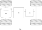
- FIG 1 a structural view of a vehicle 1 of an embodiment of the present application is shown.
- the vehicle 1 can be a fuel vehicle, a gas vehicle or a new energy vehicle, and the new energy vehicle can be a pure electric vehicle, a hybrid vehicle or extended-range cars, etc.
- a drive motor 180 is attached to front axles of the two front wheels of the vehicle.
- the vehicle is also equipped with a controller 190 and a battery 100.
- the controller 190 and battery 100 are typically disposed at appropriate locations on a main shaft of the vehicle in order to control the operation of various components of the vehicle and to provide driving power for the vehicle.
- the battery 100 may include a plurality of battery cells 100a.
- the plurality of battery cells 100a may be connected in series or in parallel or in a mixed connection, and the mixed connection refers to a mixture of the series connection and the parallel connection.
- the battery 100 may also be referred to as a battery pack.
- the plurality of battery cells 100a may be connected in series or in parallel or in the mixed connection to form a battery module, and then a plurality of battery modules may be connected in series or in parallel or in the mixed connection to form the battery 100. That is to say, the plurality of battery cells 100a can directly form the battery 100, or the battery module can be formed at first, and then the battery module forms the battery 100.
- the battery 100 may include the plurality of battery cells 100a.
- the battery 100 may further include a case.
- the case has a hollow structure, and the plurality of battery cells 100a are accommodated in the case.
- the case may include two parts which are referred to here as a housing 102 and a cover 101 respectively, and the cover 101 covers the housing 102.
- the shapes of the housing 102 and the cover 101 may be determined according to the shape of the plurality of battery cells 100a which have been combined, and each of the housing 102 and the cover 101 may have one opening.
- each of the housing 102 and the cover 101 may be a hollow cuboid with only one surface being configured as an open surface, the opening of the housing 102 and the opening of the cover 101 are arranged opposite to each other, and the cover 101 covers the housing 102 to form the casing having a closed chamber.
- the plurality of battery cells 100a are connected in parallel or in series or in a mixed connection with each other, and then placed in the casing formed by the cover 101 and the housing 102 covered by the cover.
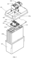
- a circuit board 103 together with the battery cells 100a are placed in the housing 102.
- a first connector 130 is mounted on the circuit board 103.
- a second connector 140 is inserted in the first connector 130 to constitute the connector assembly 120 with two connectors in pairs.
- the first connector 130 includes a base portion 131a and a protruding portion 131b extending from the base portion 131a toward the cover 101 and beyond the cover 101.
- the cover 101 is provided with an avoidance hole 101a through, the protruding portion 131b of the first connector 130 protrudes from the cover 101 via the avoidance hole and is inserted in the second connector 140 located outside the cover 101.
- the base portion 131a of the first connector 130 is provided with at least one (four in this embodiment) fastening holes 135, and the same number of screw holes 104 are correspondingly provided around the avoidance hole 101a of the cover 101.
- the base portion 131a of the first connector 130 is fixed to the cover 101 with fasteners (e.g., screws, bolts, etc.).
- the base portion 131a of the first connector 130, the circuit board 103 and the battery cell 100a are sealed in the housing 102.
- the protruding portion 131b of the first connector 130 is configured to pass through the avoidance hole 101a and inserted in the second connector 140 outside the cover 101 to constitute the connector assembly 120 with two connectors in pairs.
- the circuit board 103 is also provided with a signal circuit.
- the signal circuit is configured to be turned on through the position assurance apparatus 150 when the second connector 140 is inserted in the first connector 130 in place.
- the specific structure of the position assurance apparatus 150 will be described in detail below.
- the battery 100 further includes a battery management system (not shown in the figure), which can detect the voltage of the signal circuit and issue an alarm signal when the voltage is zero to prompt that the connector assembly 120 is not properly inserted.
- a battery management system (not shown in the figure)
- the connector assembly 120 includes the first connector 130 to be connected with the signal circuit of the circuit board 103 (not shown in FIG 4 ), the second connector 140 having an opening 146, and the position assurance apparatus 150.
- the second connector 140 is configured to be inserted in the first connector 130, and the position assurance apparatus 150 is configured to be pressed into the opening 146 to turn on the signal circuit when the second connector 140 is inserted in the first connector 130 in place.
- the first connector 130 is provided with metal power terminals 132, LIN wire solder pins 133, and signal wire pins 134. One or more of the metal power terminals 132, LIN wire solder pins 133 and signal wire pins 134 are directly soldered to the circuit board 103 using means, such as wave soldering.
- the first connector 130 is integrally sealed via a socket sealing ring.
- the second connector 140 includes a plug body 141 provided with an opening 146, a wire cover 143 sealed to a first end of the plug body 141 with a wire sealing ring 142, and a sliding cover 145a provided at a second end of the plug body 141 and slides back and forth on the plug body 141.
- the second connector 140 is integrally sealed via a plug seal 144. Except for the plug body 141 provided with the opening 146 and the sliding cover 145, the above-mentioned other components are well known to those skilled in the art, and thus further description of these components is omitted.
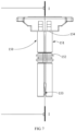
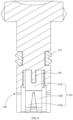
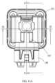
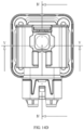
- FIG 5, FIG 6 , FIG 7 and FIG 8 are a perspective view, an exploded view, a side view and a sectional view of the position assurance apparatus 150 according to an embodiment of the present disclosure, respectively.
- the position assurance apparatus 150 includes a body portion 151, a sealing ring 152 and a conductive sheet 153.
- the body portion 151 is formed by injection molding, and a ring groove for accommodating the sealing ring 152 is provided in the middle portion of the body portion 151.
- the ring groove divides the body portion 151 into two portions, i.e., an upper body portion 151a and a lower body portion 151b. At least a part of the upper body portion 151a, usually both sides of the top of the upper body portion 151a, are formed with abutting portions 154, and a side of each abutting portion 154 facing the sealing ring 152 is flat.
- the lower body portion 151b is in the shape of a hollow sleeve.
- An engaging portion 156 that is engaged with the conductive sheet 153 is formed in the hollow sleeve of the lower body portion 151b.
- the engaging portion 156 is a protrusion protruding from the inner surface of the hollow sleeve, but those skilled in the art can also use other forms of elements to engage the conductive sheet 153. After the conductive sheet 153 is engaged with the engaging portion 156 of the lower body portion 151b, the conductive sheet 153 is almost invisible when viewed from the outside of the position assurance apparatus 150.
- the conductive sheet 153 includes a first connecting portion 153a and a second connecting portion 153b electrically connected to the first connecting portion 153a.
- the first connecting portion 153a and the second connecting portion 153b are configured to be electrically connected with the signal circuit via the first connector 130 (not shown in the figure), to turn on the signal circuit when the second connector 140 is inserted in the first connector 130 in place.
- FIG 6A is an enlarged view of the conductive sheet 153 of another embodiment as shown in FIG 6 .
- This figure clearly shows the configuration of the conductive sheet 153 that is engaged inside the lower body portion 151b.
- the conductive sheet 153 includes at least a first connecting portion 153a and a second connecting portion 153b that are bifurcated in a "V" shape.
- Both the first connecting portion 153a and the second connecting portion 153b are conductive and made of such as metal.
- the first connecting portion 153a and the second connecting portion 153b are configured to be electrically connected to each other.
- the first connecting portion 153a and the second connecting portion 153b are also electrically connected to the signal circuit from the circuit board 103 through two of the three LIN wire solder pins 133 of the first connector 130 to turn on the signal circuit when the second connector 140 is inserted in the first connector 130 in place.
- the first connecting portion 153a includes two elastic tabs oppositely arranged, each elastic tab includes an elastic contacting portion configured to be electrically connected to the first connector 130.
- the first connecting portion 153a is composed of a pair of elastic tabs arranged opposite to each other, and each of the elastic tabs is an elongated metal tab with elasticity. Ends of the pair of elastic tabs approach each other and are bent to form the elastic contacting portion. A gap allowing the LIN wire solder pin 133 of the first connector 130 to be inserted therein is formed between the elastic contacting portions of the two elastic tabs. When the LIN wire solder pin 133 is inserted in the gap formed by the elastic contacting portions of the two elastic tabs, the LIN wire solder pin 133 and the first connecting portion 153a are electrically connected to each other.
- the elastic tab also includes an indentation 157, the indentation is used for reducing the distance between the elastic contacting portions of the two elastic tabs to ensure that the elastic contacting portions of the two elastic tabs can be in close contact with conductors such as the LIN wire solder pins 133.
- the second connecting portion 153b may have the same structure as the first connecting portion 153a, so the position assurance apparatus 150 is connected to a signal line.
- the conductive sheet 153 further includes a conductive base 153c.
- the conductive base 153c is in the shape of a hollow sleeve, and includes a first end and a second end disposed opposite to each other.
- the first connecting portion 153a and the second connecting portion 153b are connected to the first end of the conductive base 153c.
- the second end of the conductive base 153c forms an engaging notch 155, and the shape of the engaging notch 155 is substantially the same as that of the engaging portion 156 of the lower body portion 151b.
- the engaging notch 155 and the engaging portion 156 can cooperate to fix the conductive sheet 153 in the body portion 151 of the position assurance apparatus 150.
- a notched shape of the engaging notch 155 is serrated, to increase a frictional force when the engaging notch 155 is engaged with the engaging portion 156.
- the connector assembly 120 is further provided with a limiting member.
- the limiting member may be individually provided on the position assurance apparatus 150, the first connector 130 or the second connector 140. No matter where it is provided, it only needs to be able to prevent the position assurance apparatus 150 from being pressed into the opening 146 of the second connector 140 when the second connector 140 is not inserted in the first connector 130 in place.
- the limiting member may be a latch provided individually on the position guarantee device 150. When the connector assembly 120 is not inserted in place, the latch can abut the second connector 140 to prevent the position assurance apparatus 150 from being pressed into the opening 146. When the connector assembly 120 is inserted in place, the latch can be removed, thereby allowing the position assurance apparatus 150 to be pressed into the opening 146.
- the limiting member comprises: a first limiting element arranged on the second connector; and a second limiting element arranged on the position assurance apparatus.
- the first limiting element is configured to cooperate with the second limiting element to prevent the position assurance apparatus from being pressed into the opening to turn on the signal circuit when it is at a first position, and allows the position assurance apparatus to be pressed into the opening and turn on the signal circuit when it is at a second position.
- the limiting member is composed of at least two parts, namely: the first limiting element located in the second connector 140 and the second limiting element located in the position assurance apparatus 150.
- the first limiting element is configured to cooperate with the second limiting element to prevent the position assurance apparatus 150 from being pressed into the opening 146 to turn on the signal circuit at the first position, and allows the position assurance apparatus 150 to be pressed into the opening 146 and turn on the signal circuit.
- the first limiting element is a sliding member with a stepped portion 147, that is, a sliding cover 145.
- the second limiting element is configured as an abutting portion 154 on the position assurance apparatus 150.
- the stepped portion 147 is formed on the top of the sliding cover 145 and protrudes from the top of the sliding cover 145.
- An inner wall of the sliding cover 145 is provided with a sliding groove 148 or a similar structure for the sliding cover 145 to slide on the second connector 140.
- the abutting portion 154 provided on the top of the body portion 151 of the position assurance apparatus 150 will abut against the stepped portion 147 on the top of the sliding cover 145, to prevent the position assurance apparatus 150 from being pressed into the opening 146.
- the second connector 140 is inserted in the first connector 130 in place, the abutting portion 154 will no longer contact the stepped portion 147, thus allowing the position assurance apparatus 150 to be pressed into the opening 146 and turn on the signal circuit of the circuit board 103.
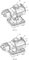
- FIGS. 9A-9D respectively show the connector assembly 120 in four states of un-assembly, pre-assembly, insertion in place and assembly in place.
- the sliding cover 145 is configured in the first position, that is, the stepped portion 147 abuts against the abutting portion 154 to prevent the position assurance apparatus 150 to be pressed into the opening 146 to turn on the signal circuit.
- the sliding cover 145 When the connector assembly 120 is in the states of insertion in place and assembly in place, the sliding cover 145 is configured in the second position, that is, the stepped portion 147 no longer abuts against the abutting portion 154 to allow the position assurance apparatus 150 to be pressed into the opening 146 to turn on the signal circuit.
- the position assurance apparatus 150 can be directly installed on the first connector 130 to reduce the number of parts to be assembled and improve the installation efficiency.
- the stepped portion 147 on the sliding cover 145 abuts against the abutting portion 154 of the position assurance apparatus 150 to prevent the position assurance apparatus 150 from being pressed down into the opening 146 of the second connector 140 to turn on the signal circuit.
- the second connector 140 is completely inserted in the first connector 130, and the connector assembly 120 is in the state of insertion in place.
- the limiting pin 136 fixed on the first connector 130 is inserted in the sliding groove 148 inside the sliding cover 145. Since the sliding groove 148 is configured in the shape of a broken line, when the sliding cover 145 is moved by an external force, the second connector 140 moves along the sliding groove 148, so the second connector 140 moves downward and is completely inserted in the first connector 130 and horizontally moves to the left, to realize that the second connector 140 is inserted in the first connector 130 in place.
- the stepped portion 147 of the second connector 140 no longer abuts against the abutting portion 154 of the position assurance apparatus 150.
- the limiting function of the limiting member is released, allowing the position assurance apparatus 150 to be pressed into the opening 146.
- the connector assembly 120 is now in the assembled state.
- the position assurance apparatus 150 is pressed into the opening 146 and fastened so the signal circuit from the circuit board 103 is turned on, prompting that the second connector 140 is inserted in the first connector 130 in place.
- a locking structure may be provided on the position assurance apparatus 150 and/or the sliding cover 145.
- the position assurance apparatus 150 and the sliding cover 145 are respectively provided with a snap protrusion and a snap recess, so after the position assurance apparatus 150 is pressed down, the snap protrusion is pressed into the snapping recess of the sliding cover 145 to achieve fastening.
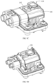
- FIG 10 is an exploded schematic view of the connector assembly 120 of another embodiment of the present disclosure, according to the claimed invention.
- the position assurance apparatus 150' is also configured to be pressed into the opening 146 and turn on the signal circuit when the second connector 140 is inserted in the first connector 130 in place.
- the structure of the first connector 130 in this embodiment is substantially the same as the structure of the first connector 130 in the above-mentioned embodiment, but it should be noted that the protruding portion 131b of the first connector 130 is provided with a limiting pin 136 protruding outwardly.
- the limiting pin 136 can cooperate with a rotation limiting groove 148' formed on a rotating handle 145' to limit the rotation of the rotating handle 145'.
- the configuration is substantially the same except that a rotary member is used to replace the sliding member as the first limiting member and a hinge pin 149 is provided to hinge the rotary handle 145' to the second connector 140.
- the first limiting element is a rotating member with a protrusion 147', that is, the rotating handle 145'.
- the rotating handle 145' is provided such as in a hinged manner at the second end of the plug body 141 and is rotatable, such as about a hinge pin 149, between the first position and the second position.
- the rotating handle 145' has a generally U-shape as a whole, and each end thereof is formed with a rotation restricting groove 148 having an arc shape as a whole and curved with a predetermined arc around the hinge hole hinged with the hinge pin 149'.
- the rotating handle 145' can rotate around the hinge pin 149 within an angular range predetermined by the rotation restricting groove 148'.
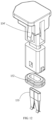
- FIGS. 11 and 12 are a perspective view and an exploded view, respectively, of a position assurance apparatus 150' used in another embodiment of the connector assembly 120.
- the position assurance apparatus 150' in this embodiment includes the body portion 151, the sealing ring 152 and the conductive sheet 153.
- the body portion 151 is formed by injection molding, and the ring groove for accommodating the sealing ring 152 is provided in the middle portion of the body portion 151.
- the ring groove divides the body portion 151 into the upper body portion 151a and the lower body portion 151b.
- the lower body portion is roughly in the shape of a hollow sleeve, or in other words, a slot for pressing the conductive sheet 153 is formed in the lower body portion.
- the elastic pieces 154' are formed on the upper body portion 151a, and the elastic pieces 154' are disposed on both sides of the position assurance apparatus 150' to serve as the second limiting element.
- the elastic piece 154' protrudes from the opening 146 of the second connector 140, thereby preventing the position assurance apparatus 150' from being pressed into the opening 146.
- the protrusion 147' of the rotating handle 145' contacts and presses the elastic piece 154' of the position assurance apparatus 150' to press the elastic piece 154' into the opening 146, thereby pressing the position guarantee device 150' into opening 146 and turning on the signal circuit from the circuit board 103.
- FIGS. 13A-13D respectively show schematic views of the connector assembly 120 in the four states of the un-assembly, pre-assembly, insertion in place and assembly in place.
- the rotating handle 145' is configured to be at the first position when the connector assembly 120 is in the states of the un-assembly and pre-assembly. That is, the elastic piece 154' protrudes from the opening 146 to prevent the position assurance apparatus 150' from being pressed into the opening 146 to turn on the signal circuit.
- the rotating handle 145' When the connector assembly 120 is in the states of insertion in place and assembly in place, the rotating handle 145' is configured to be at the second position. That is, the elastic member 154' no longer protrudes from the opening 146 to allow the position assurance apparatus 150' to be pressed into the opening 146 to turn on the signal circuit.
- the rotating handle 145' is rotated from the 180° position in the horizontal direction to a 90° position in a vertical direction, and the rotation restricting groove 148' moves relative to the limiting pin 136 in the following manner, that is, it moves from the first limiting end of the rotation restricting groove 148' where the limiting pin 136 is located to an opposite second limiting end of the rotation restricting groove 148' where the limiting pin 136 is located.
- the second connector 140 is inserted in the first connector 130 in place, and the protrusion 147' of the rotating handle 145' contacts and presses the elastic member 154' of the position assurance apparatus 150' to press the elastic member 154' into the opening 146.
- the limiting function of the limiting member is released, thus allowing the position assurance apparatus 150' to be pressed into the opening 146.
- the rotating handle 145' is no longer rotated.
- the position assurance apparatus 150' is pressed into the opening 146 and fastened so the signal circuit from the circuit board 103 is turned on, prompting that the second connector 140 is inserted in the first connector 130 in place.
- a connector assembly system can be obtained.
- the connector assembly system includes a first assembly device and a second assembly device.
- the first assembly device is used to insert the second connector 140 in the first connector 130 of the connector assembly 120 in place.
- the second assembly system is used to press the position assurance apparatus 150 into the opening 146 of the second connector 140 to turn on the signal circuit via the first connector 130.
- An embodiment of the present disclosure also provides a method for assembling the connector assembly 120, including:
- the method for assembling the connector assembly 120 further includes: when the second connector 140 is not inserted in the first connector 130 in place, operating the limiting member to prevent the position assurance apparatus 150 from being pressed into the opening of the second connector 140 and turn on the signal circuit via the first connector 130.
- FIGS. 14A-14F a method for assembling the connector assembly 120 is described in conjunction with these figures. It should be noted that although the above drawings illustrate an embodiment of the connector assembly 120, the operation methods of other alternative embodiments of the connector assembly 120 are also easily understood by those skilled in the art.
- the method mainly comprises the following three steps.
- the position assurance apparatus 150 can be prevented from being pressed into the opening 146 of the second connector 140 and turning on the signal circuit when the connector assembly 120 is not inserted in place, which can ensure the accuracy of detection.
Landscapes
- Engineering & Computer Science (AREA)
- General Chemical & Material Sciences (AREA)
- Chemical & Material Sciences (AREA)
- Chemical Kinetics & Catalysis (AREA)
- Electrochemistry (AREA)
- Microelectronics & Electronic Packaging (AREA)
- Manufacturing & Machinery (AREA)
- Sustainable Development (AREA)
- Life Sciences & Earth Sciences (AREA)
- Sustainable Energy (AREA)
- Power Engineering (AREA)
- Transportation (AREA)
- Mechanical Engineering (AREA)
- Aviation & Aerospace Engineering (AREA)
- Details Of Connecting Devices For Male And Female Coupling (AREA)
Description
- The present disclosure claims the priority to the
Chinese patent application 202011020089.X filed on September 24, 2020 - The present disclosure relates to a position assurance apparatus, a connector assembly including the position assurance apparatus, a battery including the connector assembly, a power consumption device equipped with the battery and a connector assembly system.
- In another aspect, the present disclosure also relates to a method for assembling a connector assembly.
- When an electrical signal and/or data signal and/or radio frequency signal is transmitted, it is known to use a first connector and a second connector that are inserted into each other. To ensure signal transmission, it is required that the first connector and the second connector are inserted in place during application, and the effectiveness of the insertion cannot be inadvertently destroyed during use, thereby ensuring a power, optical or data connection. However, in actual use, the first connector and the second connector often appear to be inserted in place when viewed from the outside, but they are not actually inserted in place. In order to prevent such risk, there is an urgent need for a device that can reflect in a reliable manner whether the connectors in pairs are inserted in place. The disclosure of
CN 111585103 A ,EP 3591769 A1 ,US 2015/171551 A1 ,EP 2811586 A1 andJP 2006-351415 A - In accordance with the present invention, there is provided a connector assembly comprising a first connector, a second connector and a position assurance apparatus, as recited by claim 1. The invention also foresees a method according to claim 8.
- Preferred features are set out in the dependent claims. An object of the present disclosure is to provide a position assurance apparatus, a connector assembly, a battery, a power consumption device and a connector assembly system, aiming to reflect in a reliable manner whether the connectors in pairs are inserted in place, so as to avoid a security risk caused by improper insertion connectors.
- A first, unclaimed, aspect of the present disclosure relates to a position assurance apparatus for a connector assembly connected with a signal circuit, wherein the connector assembly comprises a first connector and a second connector connected in pairs, the first connector is connected with the signal circuit, and the second connector is inserted in the first connector, the position assurance apparatus comprising:
- a first connecting portion;
- a second connecting portion electrically connected with the first connecting portion,
- wherein the first connecting portion and the second connecting portion are configured to be electrically connected with the signal circuit via the first connector, so as to turn on the signal circuit when the second connector is inserted in the first connector in place.
- In some embodiments of the present disclosure, the first connecting portion comprises two elastic tabs disposed opposite to each other, and each of the elastic tabs comprises an elastic contacting portion configured to be electrically connected with the first connector.
- In some embodiments of the present disclosure, each of the two elastic tabs comprises an indentation, and the indentation is used for reducing a distance between the elastic contacting portions of the two elastic tabs, to ensure that at least a part of the first connector inserted between the elastic contacting portions of the two elastic tabs is in close contact with the elastic contacting portion.
- In some embodiments of the present disclosure, the position assurance apparatus comprises a conductive base in a shape of a hollow sleeve, wherein the conductive base comprises a first end and a second end disposed opposite to each other, and the first connecting portion and the second connecting portion are configured to be connected with the first end.
- In some embodiments of the present disclosure, the position assurance apparatus comprises a body portion provided with a slot, wherein the second end of the conductive base is configured to be matched with the slot so that the conductive base is mounted on the body portion.
- A second aspect of the present disclosure relates to a connector assembly comprising: a first connector to be connected with a signal circuit; a second connector comprising an opening and configured to be inserted in the first connector; and the position assurance apparatus according in the first aspect of the present disclosure to be pressed into the opening and turn on the signal circuit when the second connector is inserted in the first connector in place.
- The connector assembly comprises a limiting member for preventing the position assurance apparatus from being pressed into the opening and turning on the signal circuit via the first connector when the second connector is not inserted in the first connector in place.
- The limiting member comprises: a first limiting element disposed on the second connector; a second limiting element disposed on the position assurance apparatus, wherein the first limiting element is configured to be engaged with the second limiting element to prevent the position assurance apparatus from being pressed into the opening to turn on the signal circuit when it is in the first position, and allow the position assurance apparatus to be pressed into the opening and turn on the signal circuit when it is in the second position.
- The second limiting element comprises elastic pieces disposed on both sides of the position assurance apparatus, and the elastic pieces are configured to protrude from the opening when the first limiting member rotates to the first position to prevent the position assurance apparatus from being pressed into the opening.
- The first limiting element is configured as a rotating member comprising a protrusion, and the protrusion is configured to press the elastic pieces into the opening when the first limiting element rotates to the second position, thereby allowing pressing the position assurance apparatus into the opening.
- In some unclaimed embodiments of the present disclosure, the first limiting element is configured as a sliding member comprising a stepped portion, and the stepped portion is configured to allow the position assurance apparatus to be pressed into the opening and turn on the signal circuit when the first limiting element moves to the second position.
- In some embodiments of the present disclosure, the second limiting element comprises an abutting portion, and the abutting portion is configured to abut against the stepped portion when the first limiting element moves to the first position, to prevent the position assurance apparatus from being pressed into the opening.
- A third aspect of the present disclosure relates to a battery comprising: a battery cell; the connector assembly in the second aspect of the present disclosure; a circuit board comprising a signal circuit, wherein the signal circuit is configured to be turned on via the position assurance apparatus when the second connector is inserted in the first connector in place; a battery management system used to detect a voltage of the signal circuit and issue an alarm signal when the voltage is zero to prompt that the connector assembly is not inserted in place.
- A fourth aspect of the present disclosure relates to a power consumption device comprising the battery in the third aspect of the present disclosure.
- A fifth, unclaimed, aspect of the present disclosure relates to a connector assembly system comprising: a first assembly device configured to insert a second connector in a first connector of a connector assembly in place; a second assembly device configured to press the position assurance apparatus into the opening of the second connector and turn on a signal circuit via the first connector.
- A sixth aspect of the present disclosure relates to a method for assembling a connector assembly comprising steps of: inserting a second connector in a first connector of the connector assembly in place; pressing the position assurance apparatus in the first aspect of the present disclosure into an opening of the second connector and turning on a signal circuit via the first connector.
- In some embodiments of the present disclosure, the method for assembling a connector assembly further comprises steps of: operating the limiting member when the second connector is not inserted in the first connector in place, to prevent the position assurance apparatus from being pressed into the opening and turning on the signal circuit via the first connector.
- The connector assembly with the position assurance apparatus according to the present disclosure has following advantages.
- (i) The signal circuit from the circuit board is used to determine whether the connectors in pairs are inserted in place, and compared with a traditional manual marking method, the detection method is simple and effective.
- (ii) During the use of the vehicle, it is possible to directly detect whether the connector assembly fails, thereby improving the safety of the connector assembly in use.
- (iii) Compared with a high voltage interlock connector or a micro switch as a position assurance apparatus conventionally used, the detection cost is reduced.
- In order to further illustrate the position assurance apparatus, connector assembly, battery, power consumption device, connector assembly system and the method for assembling a connector assembly of the present disclosure, the present disclosure will be described in detail below in conjunction with accompanying drawings and specific embodiments.
-
Figures 2-9D and14A-14F relate to an embodiment which is not part of the present invention, the latter being described herein below in relation withfigures 1 and10 to 13D . -
FIG 1 is a structural view of a vehicle according to an embodiment of the present disclosure; -
FIG 2 shows a battery equipped with a connector assembly of the present disclosure; -
FIG 3 is an exploded view of the battery shown inFIG 2 ; -
FIG 4 is an exploded schematic view of a connector assembly of an embodiment of the present disclosure; -
FIG 5 is a perspective view of a position assurance apparatus in an embodiment used in a connector assembly; -
FIG 6 is an exploded view of the position assurance apparatus shown inFIG 5 ; -
FIG 6A is an enlarged schematic view of a conductive sheet in another embodiment of the position assurance apparatus inFIG 6 ; -
FIG 7 is a side view of the position assurance apparatus shown inFIG 5 ; -
FIG 8 is a sectional view of the position assurance apparatus taken along line I-I inFIG 7 ; -
FIGS. 9A-9D show operation steps of the connector assembly shown inFIG 4 , wherein schematic diagrams respectively shown the connector assembly in four states of un-assembly, pre-assembly, insertion in place and assembly in place; -
FIG 10 is an exploded schematic view of a connector assembly according to another embodiment of the present disclosure; -
FIG 11 is a perspective view of a position assurance apparatus in another embodiment used in a connector assembly; -
FIG 12 is an exploded view of the position assurance apparatus shown inFIG 11 ; -
FIGS. 13A-13D show operation steps of the connector assembly shown inFIG 10 , wherein schematic diagrams respectively shown the connector assembly in four states: un-assembled, pre-assembly, insertion in place and assembly in place; -
FIGS. 14A-14C show a connector assembly before the position assurance apparatus of the present disclosure is assembled in place, whereinFIG 14A is a top plan view of the connector assembly, andFIG 14B is sectional view of the connector assembly taken along line II-II inFIG. 14B, and FIG 14C is a sectional view of the connector assembly taken along line III-III inFIG 14A ; and -
FIGS. 14D-14F show a connector assembly after the position assurance apparatus of the present disclosure is assembled in place, whereinFIG 14D is a top plan view of the connector assembly,FIG 14E is a sectional view of the connector assembly taken along line IV-IV inFIG 14D , andFIG 14F is a sectional view of the connector assembly taken along line V-V inFIG. 14D . - A
position assurance apparatus 150, aconnector assembly 120, abattery 100, a power consumption device, a connector assembly system, and a method for assembling theconnector assembly 120 of the present disclosure will be described in conjunction with accompanying drawings below. The same parts are designated with the same reference numeral. - It should be clear that embodiments described in this specification only cover a part of the embodiments of the present disclosure, but not all of the embodiments. Based on the embodiments described in the specification, all other embodiments obtained by those of ordinary skill in the art without creative work fall within the protection scope of the present disclosure.
- Unless otherwise defined, all technical and scientific terms used in the present disclosure have the same meaning as commonly understood by those skilled in the technical field of the present disclosure. The terms used in the specification of the present disclosure in the present disclosure are only for the purpose of describing specific examples, and are not intended to limit the present disclosure. The terms "comprising" and "having" in the description and claims of the present disclosure and the brief description of the drawings, as well as any variations thereof, are intended to cover non-exclusive inclusions. The terms "first", "second" and the like in the description and claims of the present disclosure or the above drawings are used to distinguish different objects, rather than to describe a specific order or primary and secondary relationship.
- The terms used in the embodiments of the present disclosure are only for the purpose of describing specific embodiments, and are not intended to limit the present disclosure. As used in the embodiments of the present disclosure and the appended claims, the singular forms "a," "the," and "the" are intended to include the plural forms as well, unless otherwise indicated.
- In the description of the present disclosure, it should be noted that, unless otherwise expressly specified and limited, the terms "installed", "connected to", "connected with" "attached" and the like should be understood in a broad sense, for example, it may be a fixed connection, a detachable connection, or an integral connection; it can be a direct connection, an indirect connection through an intermediate medium, or an internal communication between two components. For those of ordinary skill in the art, the specific meanings of the above terms in the present disclosure can be understood according to specific situations.
- In the description of the present disclosure, the term "inserted in place" means that when the second connector of the connectors in pairs is inserted in the corresponding first connector, the second connector is securely inserted in the first connector by a mechanical structure. This meaning is easily understood and defined by those of ordinary skill in the art.
- In the present disclosure, a battery cell can include lithium ion secondary battery, lithium ion primary battery, lithium sulfur battery, sodium lithium ion battery, sodium ion battery or magnesium ion battery, etc., which is not limited in the embodiment of the present disclosure. The battery cell may be in the form of a cylinder, a flat body, a rectangular parallelepiped, or other shapes, which are not limited in an embodiment of the present disclosure. The battery cell is generally divided into three types according to a packaging method: a cylindrical battery cell, a square-shaped battery cell, and a soft-pack battery cell, which are not limited in an embodiment of the present disclosure.
- The battery mentioned in the embodiments of the present disclosure refers to a single physical module including one or more battery cells to provide higher voltage and capacity. For example, the battery mentioned in the present disclosure may include a battery module or a battery pack, and the like. The battery typically includes a case for enclosing one or more battery cells. The case can prevent liquids or other foreign objects from affecting charging or discharging of the battery cell.
- The battery cell includes an electrode assembly and an electrolyte, and the electrode assembly is made up of a positive electrode sheet, a negative electrode sheet and a separating film. The battery cell works mainly by metal ions moving between the positive sheet and negative sheet. The positive sheet includes a positive current collector and a positive active material layer coated on a surface of the positive current collector. The current collector without the positive active material layer protrudes from the current collector coated with the positive active material layer, and the current collector not coated with the positive active material layer serves as the positive tab. Taking the lithium-ion battery as an example, the material of the positive current collector can be aluminum, and the positive active material can be lithium cobalt oxide, lithium iron phosphate, ternary lithium, or lithium manganate. The negative sheet comprises a negative current collector and a negative active material layer. The negative active material layer is coated on a surface of the negative current collector. The current collector without the negative electrode active material layer protrudes from the current collector coated with the negative electrode active material layer. The current collector not coated with the negative active material layer serves as the negative tab. The material of the negative current collector can be copper, and the negative active material can be carbon or silicon. In order to ensure that a large current is passed without fusing, multiple positive tabs are provided and stacked together, and multiple negative tabs are provided and stacked together. The material of the separating film can be PP or PE, etc. In addition, the electrode assembly may be in a wound structure or a laminated structure, and the embodiment of the present disclosure is not limited thereto.
- The applicant found that although the conventional position assurance apparatus utilizes a mechanical structure to ensure that the connector assembly with two connectors fully inserted with each other, it cannot directly detect whether the connector assembly has been fully inserted. A current common practice is to use manual marking to confirm that the connector is inserted in place, and its work accuracy and efficiency need to be improved. In addition, the conventional connector position assurance apparatus is at risk of vibration failure or detachment when the inserted connector assembly is subjected to shock and/or vibration, but users cannot directly detect whether the position assurance apparatus at the connector has vibration failure or detachment.
- In view of this, the present disclosure solves the above-mentioned technical problem by providing a position assurance apparatus. The present disclosure is different from the prior art in the technical concept of confirming that the connector assembly is inserted in place by using a mechanical structure, and innovatively introduces a circuit into the connector assembly and judges whether the connector assembly is inserted in place by detecting whether the circuit is connected or not, obtaining an unexpected technical effect.
- The technical solutions described in the embodiments of the present disclosure are all applicable to various devices using the battery, such as a mobile phone, a portable device, a notebook computer, a battery car, an electric toy, an electric tool, an electric vehicle, a ship, a spacecraft, etc. For example, the spacecraft includes an airplane, a rocket, a space shuttle, and a spaceship.
- It should be understood that the technical solution described in the embodiment of the present disclosure is not only limited to the equipment described above, but also applicable to all equipment using batteries, but for the sake of brevity, the following embodiments all take electric vehicles as an example.
- As shown in
FIG 1 , a structural view of a vehicle 1 of an embodiment of the present application is shown. The vehicle 1 can be a fuel vehicle, a gas vehicle or a new energy vehicle, and the new energy vehicle can be a pure electric vehicle, a hybrid vehicle or extended-range cars, etc. Adrive motor 180 is attached to front axles of the two front wheels of the vehicle. In addition, the vehicle is also equipped with acontroller 190 and abattery 100. As is well known to those of ordinary skill in the art, thecontroller 190 andbattery 100 are typically disposed at appropriate locations on a main shaft of the vehicle in order to control the operation of various components of the vehicle and to provide driving power for the vehicle. - In order to meet different power usage requirements, the
battery 100 may include a plurality ofbattery cells 100a. The plurality ofbattery cells 100a may be connected in series or in parallel or in a mixed connection, and the mixed connection refers to a mixture of the series connection and the parallel connection. Thebattery 100 may also be referred to as a battery pack. Optionally, the plurality ofbattery cells 100a may be connected in series or in parallel or in the mixed connection to form a battery module, and then a plurality of battery modules may be connected in series or in parallel or in the mixed connection to form thebattery 100. That is to say, the plurality ofbattery cells 100a can directly form thebattery 100, or the battery module can be formed at first, and then the battery module forms thebattery 100. - As shown in
FIGS. 2 and3 , a schematic structural view and an exploded view of thebattery 100 according to an embodiment of the present disclosure are shown respectively, thebattery 100 may include the plurality ofbattery cells 100a. Thebattery 100 may further include a case. The case has a hollow structure, and the plurality ofbattery cells 100a are accommodated in the case. As shown inFIG 3 , the case may include two parts which are referred to here as ahousing 102 and acover 101 respectively, and thecover 101 covers thehousing 102. The shapes of thehousing 102 and thecover 101 may be determined according to the shape of the plurality ofbattery cells 100a which have been combined, and each of thehousing 102 and thecover 101 may have one opening. For example, each of thehousing 102 and thecover 101 may be a hollow cuboid with only one surface being configured as an open surface, the opening of thehousing 102 and the opening of thecover 101 are arranged opposite to each other, and thecover 101 covers thehousing 102 to form the casing having a closed chamber. The plurality ofbattery cells 100a are connected in parallel or in series or in a mixed connection with each other, and then placed in the casing formed by thecover 101 and thehousing 102 covered by the cover. - A
circuit board 103 together with thebattery cells 100a are placed in thehousing 102. Afirst connector 130 is mounted on thecircuit board 103. Asecond connector 140 is inserted in thefirst connector 130 to constitute theconnector assembly 120 with two connectors in pairs. Thefirst connector 130 includes abase portion 131a and a protrudingportion 131b extending from thebase portion 131a toward thecover 101 and beyond thecover 101. Thecover 101 is provided with anavoidance hole 101a through, the protrudingportion 131b of thefirst connector 130 protrudes from thecover 101 via the avoidance hole and is inserted in thesecond connector 140 located outside thecover 101. Thebase portion 131a of thefirst connector 130 is provided with at least one (four in this embodiment) fastening holes 135, and the same number of screw holes 104 are correspondingly provided around theavoidance hole 101a of thecover 101. Thebase portion 131a of thefirst connector 130 is fixed to thecover 101 with fasteners (e.g., screws, bolts, etc.). - Via the above arrangement, the
base portion 131a of thefirst connector 130, thecircuit board 103 and thebattery cell 100a are sealed in thehousing 102. The protrudingportion 131b of thefirst connector 130 is configured to pass through theavoidance hole 101a and inserted in thesecond connector 140 outside thecover 101 to constitute theconnector assembly 120 with two connectors in pairs. - The
circuit board 103 is also provided with a signal circuit. The signal circuit is configured to be turned on through theposition assurance apparatus 150 when thesecond connector 140 is inserted in thefirst connector 130 in place. The specific structure of theposition assurance apparatus 150 will be described in detail below. - The
battery 100 further includes a battery management system (not shown in the figure), which can detect the voltage of the signal circuit and issue an alarm signal when the voltage is zero to prompt that theconnector assembly 120 is not properly inserted. Of course, those skilled in the art can easily understand that means, such as voice control and lighting, can also be used to prompt that theconnector assembly 120 is not properly inserted, and these means should be regarded as equivalent embodiments of the present disclosure. As shown inFIG 4 , it is an exploded schematic view of theconnector assembly 120 according to an embodiment of the present disclosure. Theconnector assembly 120 includes thefirst connector 130 to be connected with the signal circuit of the circuit board 103 (not shown inFIG 4 ), thesecond connector 140 having anopening 146, and theposition assurance apparatus 150. Thesecond connector 140 is configured to be inserted in thefirst connector 130, and theposition assurance apparatus 150 is configured to be pressed into theopening 146 to turn on the signal circuit when thesecond connector 140 is inserted in thefirst connector 130 in place. - The
first connector 130 is provided withmetal power terminals 132, LIN wire solder pins 133, and signal wire pins 134. One or more of themetal power terminals 132, LIN wire solder pins 133 and signal wire pins 134 are directly soldered to thecircuit board 103 using means, such as wave soldering. Thefirst connector 130 is integrally sealed via a socket sealing ring. Thesecond connector 140 includes aplug body 141 provided with anopening 146, awire cover 143 sealed to a first end of theplug body 141 with awire sealing ring 142, and a sliding cover 145a provided at a second end of theplug body 141 and slides back and forth on theplug body 141. Thesecond connector 140 is integrally sealed via aplug seal 144. Except for theplug body 141 provided with theopening 146 and the slidingcover 145, the above-mentioned other components are well known to those skilled in the art, and thus further description of these components is omitted. -
FIG 5, FIG 6 ,FIG 7 andFIG 8 are a perspective view, an exploded view, a side view and a sectional view of theposition assurance apparatus 150 according to an embodiment of the present disclosure, respectively. Referring toFIGS. 5, 6 ,7 and8 , theposition assurance apparatus 150 includes abody portion 151, a sealingring 152 and aconductive sheet 153. Thebody portion 151 is formed by injection molding, and a ring groove for accommodating thesealing ring 152 is provided in the middle portion of thebody portion 151. The ring groove divides thebody portion 151 into two portions, i.e., anupper body portion 151a and a lower body portion 151b. At least a part of theupper body portion 151a, usually both sides of the top of theupper body portion 151a, are formed with abuttingportions 154, and a side of eachabutting portion 154 facing the sealingring 152 is flat. - Continuing to refer to
FIGS. 5, 6 ,7 and8 , the lower body portion 151b is in the shape of a hollow sleeve. An engagingportion 156 that is engaged with theconductive sheet 153 is formed in the hollow sleeve of the lower body portion 151b. In this embodiment, the engagingportion 156 is a protrusion protruding from the inner surface of the hollow sleeve, but those skilled in the art can also use other forms of elements to engage theconductive sheet 153. After theconductive sheet 153 is engaged with the engagingportion 156 of the lower body portion 151b, theconductive sheet 153 is almost invisible when viewed from the outside of theposition assurance apparatus 150. - Referring to
FIGS. 2 and6 , theconductive sheet 153 includes a first connectingportion 153a and a second connectingportion 153b electrically connected to the first connectingportion 153a. The first connectingportion 153a and the second connectingportion 153b are configured to be electrically connected with the signal circuit via the first connector 130 (not shown in the figure), to turn on the signal circuit when thesecond connector 140 is inserted in thefirst connector 130 in place. -
FIG 6A is an enlarged view of theconductive sheet 153 of another embodiment as shown inFIG 6 . This figure clearly shows the configuration of theconductive sheet 153 that is engaged inside the lower body portion 151b. Referring toFIG. 6A , it can be seen that theconductive sheet 153 includes at least a first connectingportion 153a and a second connectingportion 153b that are bifurcated in a "V" shape. Both the first connectingportion 153a and the second connectingportion 153b are conductive and made of such as metal. The first connectingportion 153a and the second connectingportion 153b are configured to be electrically connected to each other. The first connectingportion 153a and the second connectingportion 153b are also electrically connected to the signal circuit from thecircuit board 103 through two of the three LIN wire solder pins 133 of thefirst connector 130 to turn on the signal circuit when thesecond connector 140 is inserted in thefirst connector 130 in place. - In some embodiments, the first connecting
portion 153a includes two elastic tabs oppositely arranged, each elastic tab includes an elastic contacting portion configured to be electrically connected to thefirst connector 130. - As shown in
FIG 6A , the first connectingportion 153a is composed of a pair of elastic tabs arranged opposite to each other, and each of the elastic tabs is an elongated metal tab with elasticity. Ends of the pair of elastic tabs approach each other and are bent to form the elastic contacting portion. A gap allowing the LINwire solder pin 133 of thefirst connector 130 to be inserted therein is formed between the elastic contacting portions of the two elastic tabs. When the LINwire solder pin 133 is inserted in the gap formed by the elastic contacting portions of the two elastic tabs, the LINwire solder pin 133 and the first connectingportion 153a are electrically connected to each other. The elastic tab also includes anindentation 157, the indentation is used for reducing the distance between the elastic contacting portions of the two elastic tabs to ensure that the elastic contacting portions of the two elastic tabs can be in close contact with conductors such as the LIN wire solder pins 133. It can be understood that the second connectingportion 153b may have the same structure as the first connectingportion 153a, so theposition assurance apparatus 150 is connected to a signal line. Optionally, theconductive sheet 153 further includes aconductive base 153c. Theconductive base 153c is in the shape of a hollow sleeve, and includes a first end and a second end disposed opposite to each other. The first connectingportion 153a and the second connectingportion 153b are connected to the first end of theconductive base 153c. Optionally, the second end of theconductive base 153c forms an engagingnotch 155, and the shape of the engagingnotch 155 is substantially the same as that of the engagingportion 156 of the lower body portion 151b. In this way, the engagingnotch 155 and the engagingportion 156 can cooperate to fix theconductive sheet 153 in thebody portion 151 of theposition assurance apparatus 150. Optionally, a notched shape of the engagingnotch 155 is serrated, to increase a frictional force when the engagingnotch 155 is engaged with the engagingportion 156. In order to prevent theposition assurance apparatus 150 from being pressed into theopening 146 and turning on the signal circuit via thefirst connector 130 when thesecond connector 140 is not inserted in thefirst connector 130 in place, theconnector assembly 120 is further provided with a limiting member. - In some embodiments, the limiting member may be individually provided on the
position assurance apparatus 150, thefirst connector 130 or thesecond connector 140. No matter where it is provided, it only needs to be able to prevent theposition assurance apparatus 150 from being pressed into theopening 146 of thesecond connector 140 when thesecond connector 140 is not inserted in thefirst connector 130 in place. For example, the limiting member may be a latch provided individually on theposition guarantee device 150. When theconnector assembly 120 is not inserted in place, the latch can abut thesecond connector 140 to prevent theposition assurance apparatus 150 from being pressed into theopening 146. When theconnector assembly 120 is inserted in place, the latch can be removed, thereby allowing theposition assurance apparatus 150 to be pressed into theopening 146. - In some embodiments, the limiting member comprises: a first limiting element arranged on the second connector; and a second limiting element arranged on the position assurance apparatus. The first limiting element is configured to cooperate with the second limiting element to prevent the position assurance apparatus from being pressed into the opening to turn on the signal circuit when it is at a first position, and allows the position assurance apparatus to be pressed into the opening and turn on the signal circuit when it is at a second position. Specifically, the limiting member is composed of at least two parts, namely: the first limiting element located in the
second connector 140 and the second limiting element located in theposition assurance apparatus 150. The first limiting element is configured to cooperate with the second limiting element to prevent theposition assurance apparatus 150 from being pressed into theopening 146 to turn on the signal circuit at the first position, and allows theposition assurance apparatus 150 to be pressed into theopening 146 and turn on the signal circuit. - As shown in
FIG 4 , the first limiting element is a sliding member with a steppedportion 147, that is, a slidingcover 145. The second limiting element is configured as an abuttingportion 154 on theposition assurance apparatus 150. The steppedportion 147 is formed on the top of the slidingcover 145 and protrudes from the top of the slidingcover 145. An inner wall of the slidingcover 145 is provided with a slidinggroove 148 or a similar structure for the slidingcover 145 to slide on thesecond connector 140. When the slidingcover 145 and the steppedportion 147 thereon slide to the first position on thesecond connector 140, the abuttingportion 154 provided on the top of thebody portion 151 of theposition assurance apparatus 150 will abut against the steppedportion 147 on the top of the slidingcover 145, to prevent theposition assurance apparatus 150 from being pressed into theopening 146. When the slidingcover 145 and the steppedportion 147 thereon slide to the second position on thesecond connector 140, thesecond connector 140 is inserted in thefirst connector 130 in place, the abuttingportion 154 will no longer contact the steppedportion 147, thus allowing theposition assurance apparatus 150 to be pressed into theopening 146 and turn on the signal circuit of thecircuit board 103. - Four operational steps of assembling the
connector assembly 120 will be briefly described below in conjunction withFIGS. 9A-9D. FIGS. 9A-9D respectively show theconnector assembly 120 in four states of un-assembly, pre-assembly, insertion in place and assembly in place. When theconnector assembly 120 is in the states of un-assembly and pre-assembly, the slidingcover 145 is configured in the first position, that is, the steppedportion 147 abuts against the abuttingportion 154 to prevent theposition assurance apparatus 150 to be pressed into theopening 146 to turn on the signal circuit. When theconnector assembly 120 is in the states of insertion in place and assembly in place, the slidingcover 145 is configured in the second position, that is, the steppedportion 147 no longer abuts against the abuttingportion 154 to allow theposition assurance apparatus 150 to be pressed into theopening 146 to turn on the signal circuit. - As shown in
FIG 9A , when theconnector assembly 120 is in the unassembled state, thefirst connector 130 and thesecond connector 140 are in a separated state. Optionally, theposition assurance apparatus 150 can be directly installed on thefirst connector 130 to reduce the number of parts to be assembled and improve the installation efficiency. When theconnector assembly 120 is in the unassembled state, the steppedportion 147 on the slidingcover 145 abuts against the abuttingportion 154 of theposition assurance apparatus 150 to prevent theposition assurance apparatus 150 from being pressed down into theopening 146 of thesecond connector 140 to turn on the signal circuit. - As shown in
FIG 9B , when theconnector assembly 120 is in the pre-assembled state, a portion of thesecond connector 140 is inserted in thefirst connector 130, and at this time, theconnector assembly 120 is not inserted in place. Continue to refer toFIG 4 andFIG 9B , in this state, the limitingpin 136 fixed on thefirst connector 130 has just been inserted in the slidinggroove 148 inside the slidingcover 145. At this time, the steppedportion 147 on the top of the slidingcover 145 still abuts against the abuttingportion 154 of theposition assurance apparatus 150 to prevent theposition assurance apparatus 150 from being pressed into theopening 146. - As shown in
FIG 9C , at this time, thesecond connector 140 is completely inserted in thefirst connector 130, and theconnector assembly 120 is in the state of insertion in place. Continuing to refer toFIG 4 andFIG 9C , the limitingpin 136 fixed on thefirst connector 130 is inserted in the slidinggroove 148 inside the slidingcover 145. Since the slidinggroove 148 is configured in the shape of a broken line, when the slidingcover 145 is moved by an external force, thesecond connector 140 moves along the slidinggroove 148, so thesecond connector 140 moves downward and is completely inserted in thefirst connector 130 and horizontally moves to the left, to realize that thesecond connector 140 is inserted in thefirst connector 130 in place. At the same time, the steppedportion 147 of thesecond connector 140 no longer abuts against the abuttingportion 154 of theposition assurance apparatus 150. At this time, the limiting function of the limiting member is released, allowing theposition assurance apparatus 150 to be pressed into theopening 146. - As shown in
FIG 9D , theconnector assembly 120 is now in the assembled state. Theposition assurance apparatus 150 is pressed into theopening 146 and fastened so the signal circuit from thecircuit board 103 is turned on, prompting that thesecond connector 140 is inserted in thefirst connector 130 in place. Optionally, in order to fasten theposition assurance apparatus 150, a locking structure may be provided on theposition assurance apparatus 150 and/or the slidingcover 145. For example, theposition assurance apparatus 150 and the slidingcover 145 are respectively provided with a snap protrusion and a snap recess, so after theposition assurance apparatus 150 is pressed down, the snap protrusion is pressed into the snapping recess of the slidingcover 145 to achieve fastening. -
FIG 10 is an exploded schematic view of theconnector assembly 120 of another embodiment of the present disclosure, according to the claimed invention. The position assurance apparatus 150' is also configured to be pressed into theopening 146 and turn on the signal circuit when thesecond connector 140 is inserted in thefirst connector 130 in place. - The structure of the
first connector 130 in this embodiment is substantially the same as the structure of thefirst connector 130 in the above-mentioned embodiment, but it should be noted that the protrudingportion 131b of thefirst connector 130 is provided with a limitingpin 136 protruding outwardly. In this embodiment, the limitingpin 136 can cooperate with a rotation limiting groove 148' formed on a rotating handle 145' to limit the rotation of the rotating handle 145'. As for thesecond connector 140, the configuration is substantially the same except that a rotary member is used to replace the sliding member as the first limiting member and ahinge pin 149 is provided to hinge the rotary handle 145' to thesecond connector 140. - In this embodiment, the first limiting element is a rotating member with a protrusion 147', that is, the rotating handle 145'. The rotating handle 145' is provided such as in a hinged manner at the second end of the
plug body 141 and is rotatable, such as about ahinge pin 149, between the first position and the second position. - As shown in
FIG 10 , the rotating handle 145' has a generally U-shape as a whole, and each end thereof is formed with arotation restricting groove 148 having an arc shape as a whole and curved with a predetermined arc around the hinge hole hinged with the hinge pin 149'. After therotation restricting pin 136 of thefirst connector 130 is snapped into the rotation restricting groove 148', the rotating handle 145' can rotate around thehinge pin 149 within an angular range predetermined by the rotation restricting groove 148'. -
FIGS. 11 and12 are a perspective view and an exploded view, respectively, of a position assurance apparatus 150' used in another embodiment of theconnector assembly 120. - Similar to the above embodiment, the position assurance apparatus 150' in this embodiment includes the
body portion 151, the sealingring 152 and theconductive sheet 153. Thebody portion 151 is formed by injection molding, and the ring groove for accommodating thesealing ring 152 is provided in the middle portion of thebody portion 151. The ring groove divides thebody portion 151 into theupper body portion 151a and the lower body portion 151b. The lower body portion is roughly in the shape of a hollow sleeve, or in other words, a slot for pressing theconductive sheet 153 is formed in the lower body portion. The difference between this embodiment and the above-mentioned embodiment is that the elastic pieces 154' are formed on theupper body portion 151a, and the elastic pieces 154' are disposed on both sides of the position assurance apparatus 150' to serve as the second limiting element. - When the rotating handle 145' is at the first position, the elastic piece 154' protrudes from the
opening 146 of thesecond connector 140, thereby preventing the position assurance apparatus 150' from being pressed into theopening 146. When the rotating handle 145' is at the second position, the protrusion 147' of the rotating handle 145' contacts and presses the elastic piece 154' of the position assurance apparatus 150' to press the elastic piece 154' into theopening 146, thereby pressing the position guarantee device 150' intoopening 146 and turning on the signal circuit from thecircuit board 103. - Four operation steps of assembling the connector assembly of another
embodiment 120 will be briefly described in conjunction withFIGS. 13A-13D as follows.FIGS. 13A-13D respectively show schematic views of theconnector assembly 120 in the four states of the un-assembly, pre-assembly, insertion in place and assembly in place. The rotating handle 145' is configured to be at the first position when theconnector assembly 120 is in the states of the un-assembly and pre-assembly. That is, the elastic piece 154' protrudes from theopening 146 to prevent the position assurance apparatus 150' from being pressed into theopening 146 to turn on the signal circuit. When theconnector assembly 120 is in the states of insertion in place and assembly in place, the rotating handle 145' is configured to be at the second position. That is, the elastic member 154' no longer protrudes from theopening 146 to allow the position assurance apparatus 150' to be pressed into theopening 146 to turn on the signal circuit. - As shown in
FIG 13A , when theconnector assembly 120 is in the unassembled state, thefirst connector 130 and thesecond connector 140 are in a separated state, and the limitingpin 136 of thefirst connector 130 has not been snapped into the rotation restricting groove 148' at this time, so the rotating handle 145' and the position assurance apparatus 150' are both in a state of immobility. - As shown in
FIG 13B , when theconnector assembly 120 is in the pre-assembled state, a part of thesecond connector 140 is inserted in thefirst connector 130, and the limitingpin 136 of thefirst connector 130 are snapped into the rotation restricting groove 148'. The rotating handle 145' can be rotated about thehinge pin 149 from a 180° position in the horizontal direction. At this time, the limitingpin 136 of thefirst connector 130 is located at a first limiting end of the rotation restricting groove 148'. However, since the elastic piece 154' of the position assurance apparatus 150' protrudes from theopening 146 of thesecond connector 140, the position assurance apparatus 150' is prevented from being pressed into theopening 146. - As shown in
FIG 13C , at this time, thesecond connector 140 is completely inserted in thefirst connector 130, and theconnector assembly 120 is in the state of insertion in place. During the process from pre-assembly to insertion in place, the rotating handle 145' is rotated from the 180° position in the horizontal direction to a 90° position in a vertical direction, and the rotation restricting groove 148' moves relative to the limitingpin 136 in the following manner, that is, it moves from the first limiting end of the rotation restricting groove 148' where the limitingpin 136 is located to an opposite second limiting end of the rotation restricting groove 148' where the limitingpin 136 is located. At this time, thesecond connector 140 is inserted in thefirst connector 130 in place, and the protrusion 147' of the rotating handle 145' contacts and presses the elastic member 154' of the position assurance apparatus 150' to press the elastic member 154' into theopening 146. At this time, the limiting function of the limiting member is released, thus allowing the position assurance apparatus 150' to be pressed into theopening 146. - As shown in
FIG 13D , since the limitingpin 136 of thefirst connector 130 reaches the opposite second limiting end, the rotating handle 145' is no longer rotated. The position assurance apparatus 150' is pressed into theopening 146 and fastened so the signal circuit from thecircuit board 103 is turned on, prompting that thesecond connector 140 is inserted in thefirst connector 130 in place. - In the several embodiments of the
connector assembly 120 as described above, a connector assembly system can be obtained. The connector assembly system includes a first assembly device and a second assembly device. The first assembly device is used to insert thesecond connector 140 in thefirst connector 130 of theconnector assembly 120 in place. The second assembly system is used to press theposition assurance apparatus 150 into theopening 146 of thesecond connector 140 to turn on the signal circuit via thefirst connector 130. - An embodiment of the present disclosure also provides a method for assembling the
connector assembly 120, including: - inserting the
second connector 140 in thefirst connector 130 of theconnector assembly 120 in place; - pressing the
position assurance apparatus 150 into theopening 146 of thesecond connector 140 and turning on the signal circuit via thefirst connector 130. - In some embodiments, the method for assembling the
connector assembly 120 further includes: when thesecond connector 140 is not inserted in thefirst connector 130 in place, operating the limiting member to prevent theposition assurance apparatus 150 from being pressed into the opening of thesecond connector 140 and turn on the signal circuit via thefirst connector 130. - Referring to
FIGS. 14A-14F , a method for assembling theconnector assembly 120 is described in conjunction with these figures. It should be noted that although the above drawings illustrate an embodiment of theconnector assembly 120, the operation methods of other alternative embodiments of theconnector assembly 120 are also easily understood by those skilled in the art. - Specifically, the method mainly comprises the following three steps.
- (i) Referring to
FIGS. 14A-14C , when thesecond connector 140 is not inserted in thefirst connector 130 of theconnector assembly 120 in place, the limiting member, such as the steppedportion 147 of the slidingcover 145, is operated, so the steppedportion 147 abuts against the abuttingportion 154 of theposition assurance apparatus 150 to prevent theposition assurance apparatus 150 from being pressed into theopening 146 of thesecond connector 140 and turning on the signal circuit of thecircuit board 103 via the LIN wire solder pins 133 of thefirst connector 130. - (ii) Please refer to
FIGS. 14D-14F ; the slidingcover 145 is moved so the steppedportion 147 of the slidingcover 145 no longer abuts against the abuttingportion 154 of theposition assurance apparatus 150, and at the same time thesecond connector 140 is inserted in thefirst connector 130 of theconnector assembly 120 in place. - (iii) Continuing to refer to
FIGS. 14D-14F , theposition assurance apparatus 150 is pressed into theopening 146 of thesecond connector 140 and the signal circuit of thecircuit board 103 is turned on via thefirst connector 130. Specifically, when theposition assurance apparatus 150 is pressed into theopening 146 of thesecond connector 140, the first connectingportion 153a and the second connectingportion 153b of theposition assurance apparatus 150 are respectively electrically connected to the LIN wire solder pins 133, thus the signal circuit ofcircuit board 103 is turned on. - By providing the limiting member, when the
second connector 140 is not inserted in thefirst connector 130 of theconnector assembly 120 in place, theposition assurance apparatus 150 can be prevented from being pressed into theopening 146 of thesecond connector 140 and turning on the signal circuit when theconnector assembly 120 is not inserted in place, which can ensure the accuracy of detection. For those skilled in the art, it may be necessary to increase or decrease the steps in the above method, and such modifications should also fall within the protection scope of the present disclosure. - Although the structure of the position assurance apparatus, the connector assembly, the battery, the power consumption device, the connector assembly system and the method for assembling the connector assembly of the present disclosure have been described above with reference to several embodiments, those skilled in the art should realize that the above examples are for illustration only, and not as a limitation to the present disclosure. For example, in addition to the unclaimed sliding limiting member and the claimed rotation limiting member described in the specification, other types of limiting members and the like can also be designed based on common knowledge in the art. Therefore, modifications and variations of the present disclosure will fall within the scope of the claims of the present disclosure. In particular, as long as there is no structural conflict, each technical feature mentioned in each embodiment can be combined in any manner inasmuch as the combination falls within the scope of the claims. The present disclosure is not limited to the specific embodiments disclosed herein, but includes all technical solutions falling within the scope of the claims.
Claims (9)
- A connector assembly (120) comprising:a first connector (130) for connecting with a signal circuit;a second connector (140) comprising an opening (146) and configured to be inserted in the first connector (130); anda position assurance apparatus (150) configured to be pressed into the opening (146) to cause the signal circuit to be turned on when the second connector (140) is inserted in the first connector (130) in place,wherein the position assurance apparatus (150) comprises:a first connecting portion (153a);a second connecting portion (153b) electrically connected with the first connecting portion (153a),wherein the first connecting portion (153a) and the second connecting portion (153b) are configured to be electrically connected with the signal circuit via the first connector (130) when the second connector (140) is inserted in the first connector (130) in place;wherein the connector assembly (120) further comprises a limiting member for preventing the position assurance apparatus (150) from being pressed into the opening (146) and turning on the signal circuit via the first connector (130) when the second connector (140) is not inserted in the first connector (130) in place;wherein the limiting member comprises:a first limiting element disposed on the second connector (140);a second limiting element disposed on the position assurance apparatus (150),wherein the first limiting element is configured to be engaged with the second limiting element to prevent the position assurance apparatus (150) from being pressed into the opening (146) to turn on the signal circuit when the first limiting element is in a first position, and allow the position assurance apparatus (150) to be pressed into the opening (146) and turn on the signal circuit when the first limiting element is in a second position; wherein the second limiting element comprises elastic pieces disposed on both sides of the position assurance apparatus (150),characterized in thatthe elastic pieces are configured to protrude from the opening (146) when the first limiting member rotates to the first position to prevent the position assurance apparatus (150) from being pressed into the opening (146), andthe first limiting element is configured as a rotating member comprising a protrusion (147'), and the protrusion (147') is configured to press the elastic pieces inward into the position assurance apparatus when the first limiting element rotates to the second position, thereby allowing the position assurance apparatus (150) to be pressed into the opening (146).
- The connector assembly (120) according to claim 1, wherein the first connecting portion (153a) comprises two elastic tabs disposed opposite to each other, and each of the elastic tabs comprises an elastic contacting portion configured to be electrically connected with the first connector (130).
- The connector assembly (120) according to claim 2, wherein at least one of the two elastic tabs comprises an indentation (157), and the indentation (157) is used for reducing a distance between the elastic contacting portions of the two elastic tabs, to ensure that at least a part of the first connector (130) inserted between the elastic contacting portions of the two elastic tabs is in close contact with the elastic contacting portion.
- The connector assembly (120) according to any one of claims 1 to 3, further comprising a conductive base (153c) in a shape of a hollow sleeve, wherein the conductive base (153c) comprises a first end and a second end disposed opposite to each other, and the first connecting portion (153a) and the second connecting portion (153b) are configured to be connected with the first end.
- The connector assembly (120) according to claim 4, further comprising a body portion (151) provided with a slot, wherein the second end of the conductive base (153c) is configured to be matched with the slot so that the conductive base (153c) is mounted on the body portion (151), and optionally wherein an engaging portion (156) is formed in the slot of the body portion (151), an engaging notch (155) is formed on the second end, and the engaging notch (155) is engaged with the engaging portion (156) to fix the conductive base (153c) to the body portion (151).
- A battery (100) comprising:a battery cell (100a);the connector assembly (120) as claimed in any one of claims 1 to 5;a circuit board (103) comprising a signal circuit, wherein the signal circuit is configured to be turned on via the position assurance apparatus (150) when the second connector (140) is inserted in the first connector (130) in place;a battery management system used to detect a voltage of the signal circuit and issue an alarm signal when the voltage is zero to prompt that the connector assembly (120) is not inserted in place.
- A power consumption device
comprising the battery (100) according to claim 6. - A method for assembling the connector assembly (120) according to any one of claims 1 to 5, comprising steps of:inserting the second connector (140) in the first connector (130) of the connector assembly (120) in place;pressing the position assurance apparatus (150) into the opening (146) of the second connector (140) and turning on the signal circuit via the first connector (130).
- The method for assembling the connector assembly (120) according to claim 8, further comprising steps of:
operating the limiting member of the connector assembly (120) when the second connector (140) is not inserted in the first connector (130) in place, to prevent the position assurance apparatus (150) from being pressed into the opening (146) and turning on the signal circuit via the first connector (130).
Applications Claiming Priority (2)
| Application Number | Priority Date | Filing Date | Title |
|---|---|---|---|
| CN202011020089.XA CN112310691B (en) | 2020-09-24 | 2020-09-24 | Position assurance devices, connector assemblies, batteries and power consumers |
| PCT/CN2021/111603 WO2022062738A1 (en) | 2020-09-24 | 2021-08-09 | Position assurance apparatus, connector assembly, battery, and power consumption apparatus |
Publications (4)
| Publication Number | Publication Date |
|---|---|
| EP4099516A1 EP4099516A1 (en) | 2022-12-07 |
| EP4099516A4 EP4099516A4 (en) | 2023-09-27 |
| EP4099516C0 EP4099516C0 (en) | 2024-07-17 |
| EP4099516B1 true EP4099516B1 (en) | 2024-07-17 |
Family
ID=74488608
Family Applications (2)
| Application Number | Title | Priority Date | Filing Date |
|---|---|---|---|
| EP21871115.8A Active EP4099516B1 (en) | 2020-09-24 | 2021-08-09 | Position assurance apparatus, connector assembly, battery, and power consumption apparatus |
| EP21871615.7A Active EP4099517B1 (en) | 2020-09-24 | 2021-09-24 | Position assurance apparatus, connector assembly, battery, and electrical apparatus |
Family Applications After (1)
| Application Number | Title | Priority Date | Filing Date |
|---|---|---|---|
| EP21871615.7A Active EP4099517B1 (en) | 2020-09-24 | 2021-09-24 | Position assurance apparatus, connector assembly, battery, and electrical apparatus |
Country Status (5)
| Country | Link |
|---|---|
| US (2) | US12463388B2 (en) |
| EP (2) | EP4099516B1 (en) |
| CN (2) | CN112310691B (en) |
| HU (1) | HUE069036T2 (en) |
| WO (2) | WO2022062738A1 (en) |
Families Citing this family (6)
| Publication number | Priority date | Publication date | Assignee | Title |
|---|---|---|---|---|
| CN112310691B (en) | 2020-09-24 | 2023-11-10 | 宁德时代新能源科技股份有限公司 | Position assurance devices, connector assemblies, batteries and power consumers |
| JP7444116B2 (en) * | 2021-03-16 | 2024-03-06 | 住友電装株式会社 | connector |
| DE102021213963A1 (en) | 2021-12-08 | 2023-06-15 | Mahle International Gmbh | Subassembly for a battery and battery |
| US12401160B2 (en) * | 2022-03-09 | 2025-08-26 | Tyco Electronics (Shanghai) Co., Ltd. | Connector and connector assembly |
| CN115051183A (en) * | 2022-06-21 | 2022-09-13 | 合兴汽车电子(太仓)有限公司 | Locking structure and high-voltage connector with same |
| CN115832756A (en) * | 2022-12-30 | 2023-03-21 | 奇瑞新能源汽车股份有限公司 | An electric vehicle electrical connector |
Family Cites Families (32)
| Publication number | Priority date | Publication date | Assignee | Title |
|---|---|---|---|---|
| JPH0545935U (en) * | 1991-11-22 | 1993-06-18 | 古河電気工業株式会社 | Female terminal |
| JP3264305B2 (en) * | 1995-01-09 | 2002-03-11 | 矢崎総業株式会社 | Connector with coupling detection device |
| US6062899A (en) * | 1998-09-15 | 2000-05-16 | Chrysler Corporation | Digital verification of battery cable connection to power distribution module |
| JP2006351415A (en) * | 2005-06-17 | 2006-12-28 | Auto Network Gijutsu Kenkyusho:Kk | Lever type connector |
| ATE470970T1 (en) * | 2007-08-13 | 2010-06-15 | Molex Inc | AIR BAG CONNECTOR |
| JP4930439B2 (en) * | 2008-04-04 | 2012-05-16 | 住友電装株式会社 | Terminal fitting |
| JP4848483B2 (en) * | 2009-01-28 | 2011-12-28 | 聰高 小林 | Detachment detection receiver connected to a decoupling detection outlet |
| JP5727469B2 (en) | 2009-06-09 | 2015-06-03 | エフシーアイ・オートモティヴ・ホールディング | Connector for safety restraint system |
| CN102834984B (en) * | 2010-04-09 | 2015-09-30 | 富加宜汽车控股公司 | Electrical Connector System |
| CN202205925U (en) * | 2011-09-15 | 2012-04-25 | 凹凸电子(武汉)有限公司 | Plug, socket and electric vehicle system |
| JP2014238929A (en) * | 2013-06-06 | 2014-12-18 | 日本航空電子工業株式会社 | Connector device |
| CN105531886B (en) * | 2013-09-16 | 2018-07-03 | 泰科电子法国公司 | A kind of electric connector for safety restraint system |
| JP6289042B2 (en) * | 2013-11-13 | 2018-03-07 | タイコエレクトロニクスジャパン合同会社 | Connector with connector position assurance mechanism and connector fitting |
| CN105691217B (en) * | 2014-11-29 | 2018-03-06 | 中山大洋电机股份有限公司 | A kind of integrated charge is with driving vehicle electric system and its control method in one |
| EP3116075B1 (en) * | 2015-07-08 | 2019-09-11 | Aptiv Technologies Limited | Electrical plug connector for a safety restraint system |
| EP3118943B1 (en) | 2015-07-15 | 2019-06-12 | Aptiv Technologies Limited | Electrical plug connector for a safety restraint system and connection method thereof. |
| JP6200933B2 (en) | 2015-11-10 | 2017-09-20 | タイコエレクトロニクスジャパン合同会社 | Lever type connector assembly |
| US10038278B2 (en) | 2016-03-17 | 2018-07-31 | Te Connectivity Corporation | Electrical connector having a connector position assurance element |
| CN105789997B (en) * | 2016-03-25 | 2019-05-03 | 北京新能源汽车股份有限公司 | High-voltage connector device, electric vehicle power system and electric vehicle |
| DE102016209472A1 (en) * | 2016-05-31 | 2017-11-30 | Robert Bosch Gmbh | Plug system and plug element |
| US10454209B2 (en) | 2017-05-01 | 2019-10-22 | J.S.T. Corporation | Connector position assurance device, a connector apparatus having male and female connector assemblies with connector position assurance device, a male connector assembly, a female connector assembly, and a method for assembling the connector apparatus |
| FR3067176B1 (en) * | 2017-06-03 | 2023-01-20 | Tyco Electronics France Sas | ELECTRICAL CONNECTOR COMPRISING A POSITION ASSURANCE DEVICE |
| US10270208B1 (en) * | 2017-10-20 | 2019-04-23 | Lear Corporation | Electrical connector with assist lever |
| US10218117B1 (en) | 2017-10-20 | 2019-02-26 | Lear Corporation | Electrical connector with assist lever |
| KR102362882B1 (en) | 2018-02-14 | 2022-02-11 | 주식회사 엘지에너지솔루션 | Battery pack connector |
| JP6793687B2 (en) * | 2018-07-02 | 2020-12-02 | 矢崎総業株式会社 | Connector device |
| CN208336617U (en) * | 2018-07-19 | 2019-01-04 | 宁德时代新能源科技股份有限公司 | Connector and battery case |
| EP3827481A4 (en) * | 2018-07-23 | 2022-04-20 | J.S.T. Corporation | CONNECTOR SYSTEM AND ELECTRICAL CIRCUIT FOR A CONNECTOR WITH POSITION SECURITY ELEMENT |
| FR3088491B1 (en) * | 2018-11-12 | 2021-12-03 | Raydiall | CONNECTOR BOX EQUIPPED WITH AN IMPROVED CABLE TERMINAL POSITION ASSURANCE (TPA) DEVICE |
| DE202018106428U1 (en) | 2018-11-13 | 2019-05-24 | Odu Gmbh & Co. Kg | Coupling connector with a slider part |
| CN111585103B (en) * | 2020-06-22 | 2025-02-18 | 中航光电科技股份有限公司 | A CPA push interlocking structure |
| CN112310691B (en) * | 2020-09-24 | 2023-11-10 | 宁德时代新能源科技股份有限公司 | Position assurance devices, connector assemblies, batteries and power consumers |
-
2020
- 2020-09-24 CN CN202011020089.XA patent/CN112310691B/en active Active
-
2021
- 2021-08-09 HU HUE21871115A patent/HUE069036T2/en unknown
- 2021-08-09 WO PCT/CN2021/111603 patent/WO2022062738A1/en not_active Ceased
- 2021-08-09 EP EP21871115.8A patent/EP4099516B1/en active Active
- 2021-09-24 CN CN202180049001.3A patent/CN115843402A/en active Pending
- 2021-09-24 WO PCT/CN2021/120432 patent/WO2022063246A1/en not_active Ceased
- 2021-09-24 EP EP21871615.7A patent/EP4099517B1/en active Active
-
2022
- 2022-12-05 US US18/061,484 patent/US12463388B2/en active Active
-
2023
- 2023-02-09 US US18/166,919 patent/US12506305B2/en active Active
Also Published As
| Publication number | Publication date |
|---|---|
| EP4099517A4 (en) | 2024-01-03 |
| US12463388B2 (en) | 2025-11-04 |
| EP4099516C0 (en) | 2024-07-17 |
| US20230123353A1 (en) | 2023-04-20 |
| EP4099517B1 (en) | 2026-04-01 |
| WO2022062738A1 (en) | 2022-03-31 |
| EP4099516A1 (en) | 2022-12-07 |
| WO2022063246A1 (en) | 2022-03-31 |
| CN112310691A (en) | 2021-02-02 |
| US20230187878A1 (en) | 2023-06-15 |
| US12506305B2 (en) | 2025-12-23 |
| HUE069036T2 (en) | 2025-02-28 |
| EP4099517A1 (en) | 2022-12-07 |
| EP4099516A4 (en) | 2023-09-27 |
| CN112310691B (en) | 2023-11-10 |
| CN115843402A (en) | 2023-03-24 |
Similar Documents
| Publication | Publication Date | Title |
|---|---|---|
| EP4099516B1 (en) | Position assurance apparatus, connector assembly, battery, and power consumption apparatus | |
| EP4415132B1 (en) | End cover assembly, energy storage apparatus, and electricity-consumption device | |
| RU2454754C1 (en) | Accumulator storage battery with device for connection of electrode outputs | |
| US8778530B2 (en) | Battery and battery pack using the same | |
| EP3312901B1 (en) | Secondary battery | |
| US8481183B2 (en) | Secondary battery | |
| KR20160107798A (en) | Battery Pack | |
| KR19990031352A (en) | Battery safety device | |
| CN220290875U (en) | Battery cells, batteries and electrical devices | |
| CN117083771A (en) | Connectors and electrical devices | |
| EP4395055A1 (en) | Adapter assembly, battery cell, battery, and electric device | |
| KR20150009371A (en) | Rechargeable battery | |
| CN223743723U (en) | Sampling device, battery and electric equipment | |
| CN220290877U (en) | Battery cell, battery and electricity utilization device | |
| KR20150098418A (en) | Secondary battery | |
| CN118525410A (en) | Battery cells, batteries and electrical equipment | |
| CN223023650U (en) | Electric connection assembly, battery device and electric equipment | |
| US12388143B2 (en) | Battery cell, battery, power consumption device and manufacturing device and method for battery cell | |
| EP4489197B1 (en) | Battery pack | |
| CN118899627B (en) | Battery device, power consumption device and connector | |
| US20250015403A1 (en) | End cover assembly of battery cell, battery cell, and battery | |
| EP4489196A1 (en) | Battery pack | |
| CN120814109A (en) | Battery cell, battery and electricity utilization device | |
| EP4280369A1 (en) | Battery cell, battery, electrical apparatus, and battery preparation method and apparatus | |
| CN116964837A (en) | Battery cells, batteries, electrical equipment, methods and equipment for manufacturing battery cells |
Legal Events
| Date | Code | Title | Description |
|---|---|---|---|
| STAA | Information on the status of an ep patent application or granted ep patent |
Free format text: STATUS: THE INTERNATIONAL PUBLICATION HAS BEEN MADE |
|
| PUAI | Public reference made under article 153(3) epc to a published international application that has entered the european phase |
Free format text: ORIGINAL CODE: 0009012 |
|
| STAA | Information on the status of an ep patent application or granted ep patent |
Free format text: STATUS: REQUEST FOR EXAMINATION WAS MADE |
|
| 17P | Request for examination filed |
Effective date: 20220901 |
|
| AK | Designated contracting states |
Kind code of ref document: A1 Designated state(s): AL AT BE BG CH CY CZ DE DK EE ES FI FR GB GR HR HU IE IS IT LI LT LU LV MC MK MT NL NO PL PT RO RS SE SI SK SM TR |
|
| A4 | Supplementary search report drawn up and despatched |
Effective date: 20230823 |
|
| RIC1 | Information provided on ipc code assigned before grant |
Ipc: H01M 50/249 20210101ALI20230818BHEP Ipc: H01R 31/08 20060101ALI20230818BHEP Ipc: H01M 50/296 20210101ALI20230818BHEP Ipc: H01M 50/287 20210101ALI20230818BHEP Ipc: H01M 50/271 20210101ALI20230818BHEP Ipc: H01M 50/209 20210101ALI20230818BHEP Ipc: H01M 10/42 20060101ALI20230818BHEP Ipc: B60L 50/64 20190101ALI20230818BHEP Ipc: H01R 13/629 20060101ALI20230818BHEP Ipc: H01R 13/70 20060101ALI20230818BHEP Ipc: H01R 13/641 20060101AFI20230818BHEP |
|
| DAV | Request for validation of the european patent (deleted) | ||
| DAX | Request for extension of the european patent (deleted) | ||
| GRAP | Despatch of communication of intention to grant a patent |
Free format text: ORIGINAL CODE: EPIDOSNIGR1 |
|
| STAA | Information on the status of an ep patent application or granted ep patent |
Free format text: STATUS: GRANT OF PATENT IS INTENDED |
|
| INTG | Intention to grant announced |
Effective date: 20240508 |
|
| GRAS | Grant fee paid |
Free format text: ORIGINAL CODE: EPIDOSNIGR3 |
|
| GRAA | (expected) grant |
Free format text: ORIGINAL CODE: 0009210 |
|
| STAA | Information on the status of an ep patent application or granted ep patent |
Free format text: STATUS: THE PATENT HAS BEEN GRANTED |
|
| AK | Designated contracting states |
Kind code of ref document: B1 Designated state(s): AL AT BE BG CH CY CZ DE DK EE ES FI FR GB GR HR HU IE IS IT LI LT LU LV MC MK MT NL NO PL PT RO RS SE SI SK SM TR |
|
| RAP3 | Party data changed (applicant data changed or rights of an application transferred) |
Owner name: CONTEMPORARY AMPEREX TECHNOLOGY CO., LIMITED |
|
| REG | Reference to a national code |
Ref country code: CH Ref legal event code: EP |
|
| REG | Reference to a national code |
Ref country code: DE Ref legal event code: R096 Ref document number: 602021015961 Country of ref document: DE |
|
| REG | Reference to a national code |
Ref country code: IE Ref legal event code: FG4D |
|
| U01 | Request for unitary effect filed |
Effective date: 20240808 |
|
| REG | Reference to a national code |
Ref country code: GB Ref legal event code: 732E Free format text: REGISTERED BETWEEN 20240829 AND 20240904 |
|
| RAP2 | Party data changed (patent owner data changed or rights of a patent transferred) |
Owner name: CONTEMPORARY AMPEREX TECHNOLOGY(HONG KONG) LIMITED |
|
| U07 | Unitary effect registered |
Designated state(s): AT BE BG DE DK EE FI FR IT LT LU LV MT NL PT RO SE SI Effective date: 20240905 |
|
| U20 | Renewal fee for the european patent with unitary effect paid |
Year of fee payment: 4 Effective date: 20240916 |
|
| PG25 | Lapsed in a contracting state [announced via postgrant information from national office to epo] |
Ref country code: NO Free format text: LAPSE BECAUSE OF FAILURE TO SUBMIT A TRANSLATION OF THE DESCRIPTION OR TO PAY THE FEE WITHIN THE PRESCRIBED TIME-LIMIT Effective date: 20241017 |
|
| PG25 | Lapsed in a contracting state [announced via postgrant information from national office to epo] |
Ref country code: GR Free format text: LAPSE BECAUSE OF FAILURE TO SUBMIT A TRANSLATION OF THE DESCRIPTION OR TO PAY THE FEE WITHIN THE PRESCRIBED TIME-LIMIT Effective date: 20241018 Ref country code: PL Free format text: LAPSE BECAUSE OF FAILURE TO SUBMIT A TRANSLATION OF THE DESCRIPTION OR TO PAY THE FEE WITHIN THE PRESCRIBED TIME-LIMIT Effective date: 20240717 |
|
| PG25 | Lapsed in a contracting state [announced via postgrant information from national office to epo] |
Ref country code: IS Free format text: LAPSE BECAUSE OF FAILURE TO SUBMIT A TRANSLATION OF THE DESCRIPTION OR TO PAY THE FEE WITHIN THE PRESCRIBED TIME-LIMIT Effective date: 20241117 |
|
| PG25 | Lapsed in a contracting state [announced via postgrant information from national office to epo] |
Ref country code: HR Free format text: LAPSE BECAUSE OF FAILURE TO SUBMIT A TRANSLATION OF THE DESCRIPTION OR TO PAY THE FEE WITHIN THE PRESCRIBED TIME-LIMIT Effective date: 20240717 |
|
| PG25 | Lapsed in a contracting state [announced via postgrant information from national office to epo] |
Ref country code: RS Free format text: LAPSE BECAUSE OF FAILURE TO SUBMIT A TRANSLATION OF THE DESCRIPTION OR TO PAY THE FEE WITHIN THE PRESCRIBED TIME-LIMIT Effective date: 20241017 Ref country code: ES Free format text: LAPSE BECAUSE OF FAILURE TO SUBMIT A TRANSLATION OF THE DESCRIPTION OR TO PAY THE FEE WITHIN THE PRESCRIBED TIME-LIMIT Effective date: 20240717 |
|
| PG25 | Lapsed in a contracting state [announced via postgrant information from national office to epo] |
Ref country code: RS Free format text: LAPSE BECAUSE OF FAILURE TO SUBMIT A TRANSLATION OF THE DESCRIPTION OR TO PAY THE FEE WITHIN THE PRESCRIBED TIME-LIMIT Effective date: 20241017 Ref country code: PL Free format text: LAPSE BECAUSE OF FAILURE TO SUBMIT A TRANSLATION OF THE DESCRIPTION OR TO PAY THE FEE WITHIN THE PRESCRIBED TIME-LIMIT Effective date: 20240717 Ref country code: NO Free format text: LAPSE BECAUSE OF FAILURE TO SUBMIT A TRANSLATION OF THE DESCRIPTION OR TO PAY THE FEE WITHIN THE PRESCRIBED TIME-LIMIT Effective date: 20241017 Ref country code: IS Free format text: LAPSE BECAUSE OF FAILURE TO SUBMIT A TRANSLATION OF THE DESCRIPTION OR TO PAY THE FEE WITHIN THE PRESCRIBED TIME-LIMIT Effective date: 20241117 Ref country code: HR Free format text: LAPSE BECAUSE OF FAILURE TO SUBMIT A TRANSLATION OF THE DESCRIPTION OR TO PAY THE FEE WITHIN THE PRESCRIBED TIME-LIMIT Effective date: 20240717 Ref country code: GR Free format text: LAPSE BECAUSE OF FAILURE TO SUBMIT A TRANSLATION OF THE DESCRIPTION OR TO PAY THE FEE WITHIN THE PRESCRIBED TIME-LIMIT Effective date: 20241018 Ref country code: ES Free format text: LAPSE BECAUSE OF FAILURE TO SUBMIT A TRANSLATION OF THE DESCRIPTION OR TO PAY THE FEE WITHIN THE PRESCRIBED TIME-LIMIT Effective date: 20240717 |
|
| REG | Reference to a national code |
Ref country code: HU Ref legal event code: AG4A Ref document number: E069036 Country of ref document: HU |
|
| REG | Reference to a national code |
Ref country code: CH Ref legal event code: PL |
|
| PG25 | Lapsed in a contracting state [announced via postgrant information from national office to epo] |
Ref country code: SM Free format text: LAPSE BECAUSE OF FAILURE TO SUBMIT A TRANSLATION OF THE DESCRIPTION OR TO PAY THE FEE WITHIN THE PRESCRIBED TIME-LIMIT Effective date: 20240717 |
|
| PG25 | Lapsed in a contracting state [announced via postgrant information from national office to epo] |
Ref country code: CH Free format text: LAPSE BECAUSE OF NON-PAYMENT OF DUE FEES Effective date: 20240831 Ref country code: MC Free format text: LAPSE BECAUSE OF FAILURE TO SUBMIT A TRANSLATION OF THE DESCRIPTION OR TO PAY THE FEE WITHIN THE PRESCRIBED TIME-LIMIT Effective date: 20240717 |
|
| PG25 | Lapsed in a contracting state [announced via postgrant information from national office to epo] |
Ref country code: CZ Free format text: LAPSE BECAUSE OF FAILURE TO SUBMIT A TRANSLATION OF THE DESCRIPTION OR TO PAY THE FEE WITHIN THE PRESCRIBED TIME-LIMIT Effective date: 20240717 |
|
| PG25 | Lapsed in a contracting state [announced via postgrant information from national office to epo] |
Ref country code: SK Free format text: LAPSE BECAUSE OF FAILURE TO SUBMIT A TRANSLATION OF THE DESCRIPTION OR TO PAY THE FEE WITHIN THE PRESCRIBED TIME-LIMIT Effective date: 20240717 |
|
| PLBE | No opposition filed within time limit |
Free format text: ORIGINAL CODE: 0009261 |
|
| STAA | Information on the status of an ep patent application or granted ep patent |
Free format text: STATUS: NO OPPOSITION FILED WITHIN TIME LIMIT |
|
| 26N | No opposition filed |
Effective date: 20250422 |
|
| PG25 | Lapsed in a contracting state [announced via postgrant information from national office to epo] |
Ref country code: IE Free format text: LAPSE BECAUSE OF NON-PAYMENT OF DUE FEES Effective date: 20240809 |
|
| PGFP | Annual fee paid to national office [announced via postgrant information from national office to epo] |
Ref country code: HU Payment date: 20250807 Year of fee payment: 5 |
|
| U20 | Renewal fee for the european patent with unitary effect paid |
Year of fee payment: 5 Effective date: 20250828 |
|
| PGFP | Annual fee paid to national office [announced via postgrant information from national office to epo] |
Ref country code: GB Payment date: 20250826 Year of fee payment: 5 |
|
| PG25 | Lapsed in a contracting state [announced via postgrant information from national office to epo] |
Ref country code: CY Free format text: LAPSE BECAUSE OF FAILURE TO SUBMIT A TRANSLATION OF THE DESCRIPTION OR TO PAY THE FEE WITHIN THE PRESCRIBED TIME-LIMIT; INVALID AB INITIO Effective date: 20210809 |